以下に、遊技球を遊技媒体として用いて遊技を行う遊技球使用回胴遊技機に関する一実施の形態につき図面に基づいて説明する。
Hereinafter, an embodiment relating to a revolving gaming machine using a gaming ball in which a game is played using a gaming ball as a gaming medium will be described with reference to the drawings.
本実施の形態における遊技機は、遊技に際して所定数の遊技媒体(遊技価値)としての遊技球(例えばパチンコ機と同様の遊技球:パチンコ球)の取込を必要とし、所定条件が成立した場合には複数の遊技球、場合によっては大量の遊技球が払い出されるよう構成されている。本遊技機には、遊技ホール等においてパチンコ機と共通の遊技球供給システムから遊技球の供給がなされるようになっており、パチンコ機が設置される既存の島設備(パチンコ島)に本遊技機を設置することが可能となっている。
The gaming machine in the present embodiment requires taking in a game ball (for example, a game ball similar to a pachinko machine: a pachinko ball) as a predetermined number of game media (game value) in the game, and a predetermined condition is satisfied A plurality of game balls, and in some cases, a large number of game balls are paid out. This game machine is supplied with game balls from the same game ball supply system as the pachinko machine in the game hall, etc., and this game is installed in the existing island facility (pachinko island) where the pachinko machine is installed. It is possible to install a machine.
まず、遊技機1の外観構成及び内部構造の概略を説明する。ここで、図1は遊技機1の全体を示す斜視図、図2は遊技機1の正面図、図3及び図4は遊技機1の内部開放状態を示す斜視図、図5は遊技機1の背面図である。なお以下の説明においては、特に注記しない限りは、遊技機1の正面から見た状態を基準として左右上下などの方向を記載することとする。
First, the outline of the external configuration and internal structure of the gaming machine 1 will be described. Here, FIG. 1 is a perspective view showing the entire gaming machine 1, FIG. 2 is a front view of the gaming machine 1, FIGS. 3 and 4 are perspective views showing an internal open state of the gaming machine 1, and FIG. FIG. In the following description, unless otherwise noted, directions such as left, right, up and down are described with reference to the state viewed from the front of the gaming machine 1.
遊技機1は、本体枠としての外枠2と、この外枠2に対して前方に回動可能に取り付けられた遊技機主部3とを有する。外枠2は木製の板材を四辺に連結し構成されるものであって、全体として矩形状をなしている。本遊技機1を遊技ホールに設置する際には、外枠2が島設備に取り付け固定される。外枠2を合成樹脂やアルミニウム等の金属によって構成することも可能である。図3等では隠れて図示されていないが、外枠2を構成する四辺の板材のうち右辺の板材には、その内側上下2カ所に、後述するドアブロック4に設けた施錠部材(詳しくは鉤金具125,126)を係止するための鉤受け金具が設けられている。
The gaming machine 1 has an outer frame 2 as a main body frame, and a gaming machine main part 3 attached to the outer frame 2 so as to be rotatable forward. The outer frame 2 is configured by connecting wooden plate members to four sides, and has a rectangular shape as a whole. When the gaming machine 1 is installed in the game hall, the outer frame 2 is attached and fixed to the island facility. The outer frame 2 can be made of a metal such as synthetic resin or aluminum. Although not shown in FIG. 3 or the like, the right side plate material among the four side plate materials constituting the outer frame 2 is provided with locking members (described in detail in FIGS. A hook receiving metal for locking the metal fittings 125, 126) is provided.
遊技機主部3は、扉体ユニットであるドアブロック4と、絵柄表示ユニットである面替えブロック5と、遊技球の払出ユニットである払出ブロック6とから構成されている。ドアブロック4には上下2カ所にヒンジ金具8が設けられており、このヒンジ金具8と外枠2側の上下2カ所の支持金具9とにより、ドアブロック4(遊技機主部3)が外枠2に対して回動可能に支持されている。この場合、遊技機1を正面から見て左側に回動軸線が設けられる構成となっており、遊技機主部3は正面から見て右側を回動先端部として開放される。外枠2に対して遊技機主部3が閉じた状態では、ドアブロック4の外周縁部の背面が外枠2の前面に当接するようになっている。
The gaming machine main part 3 includes a door block 4 that is a door body unit, a face changing block 5 that is a picture display unit, and a payout block 6 that is a payout unit for game balls. The door block 4 is provided with hinge metal fittings 8 at two upper and lower positions. The door metal block 4 (the main part 3 of the gaming machine) is externally connected by the hinge metal fitting 8 and the two upper and lower metal fittings 9 on the outer frame 2 side. The frame 2 is supported so as to be rotatable. In this case, the rotation axis is provided on the left side when the gaming machine 1 is viewed from the front, and the gaming machine main part 3 is opened with the right side as the rotation tip when viewed from the front. In a state where the gaming machine main part 3 is closed with respect to the outer frame 2, the rear surface of the outer peripheral edge of the door block 4 comes into contact with the front surface of the outer frame 2.
面替えブロック5はドアブロック4の背面側に取り付けられ、更に面替えブロック5を背面側から覆うようにして払出ブロック6が取り付けられている。これら面替えブロック5と払出ブロック6はドアブロック4の一部にそれぞれ回動可能に支持されており、外枠2に対してドアブロック4と一体で回動可能となるとともに、ドアブロック4に対して各々個別に回動可能となる構造を有する。
The surface changing block 5 is attached to the back side of the door block 4, and the payout block 6 is attached so as to cover the surface changing block 5 from the back side. The surface changing block 5 and the payout block 6 are rotatably supported by a part of the door block 4, and can be rotated integrally with the door block 4 with respect to the outer frame 2. In contrast, each has a structure that can be individually rotated.
ここで、遊技機主部3を構成する上記の各部材について相対的な位置関係と動作状態を簡単に説明する。図6は遊技機主部3を模式的に示す図面であり、(a)は遊技機主部3を背面側から見た図、(b),(c)はドアブロック4に対する面替えブロック5と払出ブロック6の開放動作状況を示す図である。
Here, the relative positional relationship and the operation state of each of the members constituting the gaming machine main part 3 will be briefly described. FIG. 6 is a drawing schematically showing the gaming machine main part 3, (a) is a view of the gaming machine main part 3 as seen from the back side, and (b) and (c) are the surface changing blocks 5 for the door block 4. It is a figure which shows the open | release operation | movement condition of the payout block 6.
(a)に示すように、ドアブロック4に対して面替えブロック5や払出ブロック6を開放動作させるための軸線AX1が図の右側(正面から見ると左側)に設定されている。この軸線AX1は、面替えブロック5を支持するための軸線と払出ブロック6を支持するための軸線とを兼ねるものとなっている。この場合、図示のM11,M12は面替えブロック5を支持するための支持手段であり、M21,M22,M23は払出ブロック6を支持するための支持手段である。つまり、面替えブロック5用の支持手段M11,M12は同軸となるよう上下各位置に設けられるとともに、払出ブロック6用の支持手段M21〜M23も同様に同軸となるよう上下各位置に設けられており、払出ブロック6用の支持手段M21,M22に挟まれるようにして前記支持手段M11,M12が配置されている。また特に、これら各ブロック5,6の各支持手段は全て同軸となるよう設けられている。
As shown in (a), an axis AX1 for opening the surface changing block 5 and the payout block 6 with respect to the door block 4 is set on the right side (left side when viewed from the front). The axis AX1 serves as both an axis for supporting the surface changing block 5 and an axis for supporting the payout block 6. In this case, M11 and M12 shown in the figure are support means for supporting the surface changing block 5, and M21, M22 and M23 are support means for supporting the payout block 6. That is, the support means M11 and M12 for the surface changing block 5 are provided at the upper and lower positions so as to be coaxial, and the support means M21 to M23 for the payout block 6 are similarly provided at the upper and lower positions so as to be coaxial. The support means M11 and M12 are arranged so as to be sandwiched between the support means M21 and M22 for the payout block 6. In particular, the support means of the blocks 5 and 6 are all provided coaxially.
上記構成により、(b),(c)の各動作が可能となっている。(b)では、ドアブロック4に対して面替えブロック5と払出ブロック6とを一体的に開放動作させている。また(c)では、(b)の状態から、面替えブロック5と払出ブロック6とを分離させ、面替えブロック5を前方側に回動動作させている。
With the above configuration, the operations (b) and (c) can be performed. In (b), the surface changing block 5 and the dispensing block 6 are integrally opened with respect to the door block 4. In (c), from the state of (b), the surface changing block 5 and the payout block 6 are separated, and the surface changing block 5 is rotated forward.
(ドアブロック4の説明)
次に、ドアブロック4を図7等を用いて詳細に説明する。ここで、図7はドアブロック4を後方から見た斜視図、図8,図9はドアブロック4の主要な構成を分解してそれらを前方から及び後方から示す斜視図である。なお以下のドアブロック4の説明では、図7〜図9以外にも、前述の図1や図2等を適宜用いることとする。
(Description of door block 4)
Next, the door block 4 will be described in detail with reference to FIG. Here, FIG. 7 is a perspective view of the door block 4 as viewed from the rear, and FIGS. 8 and 9 are exploded perspective views of the main structure of the door block 4 from the front and rear. In the following description of the door block 4, the above-described FIG. 1 and FIG.
ドアブロック4において、前扉体11は、前記外枠2とほぼ同等の大きさ(縦寸法及び横寸法)を有し、その背面側に重なるようにして内枠12が取り付けられている。前扉体11及び内枠12はいずれも合成樹脂材料により成形されており、背後より複数箇所でネジ締めすることにより結合されている。ただし、ドアブロック4の剛性を高めるべく、内枠12を金属材料により成形することも可能である(例えばアルミダイキャストにより成形する)。
In the door block 4, the front door body 11 has substantially the same size (vertical dimension and horizontal dimension) as the outer frame 2, and an inner frame 12 is attached so as to overlap the back side. Both the front door body 11 and the inner frame 12 are formed of a synthetic resin material, and are joined by screwing at a plurality of locations from the back. However, in order to increase the rigidity of the door block 4, the inner frame 12 can be formed of a metal material (for example, formed by aluminum die casting).
そして、前扉体11及び内枠12の背面側から透明パネル13やパネル支持部材14が組み付けられている。また、前扉体11及び内枠12の背面側には、上皿ユニット15や取込ユニット16が装着されている。
And the transparent panel 13 and the panel support member 14 are assembled | attached from the back side of the front door body 11 and the inner frame 12. As shown in FIG. Further, an upper plate unit 15 and a take-in unit 16 are mounted on the back side of the front door body 11 and the inner frame 12.
(前扉体11の説明)
前扉体11は、後述するリール図柄や液晶図柄等を視認可能とする図柄視認部、遊技に際し遊技者により手動操作される操作部、上皿部で余剰となった遊技球などを貯留するための下皿部などを備える。以下、前扉体11と内枠12とを拡大して示す斜視図(図10,図11)等を参照して前扉体11の詳細な構成を説明する。
(Description of the front door 11)
The front door 11 stores a symbol visual recognition unit that enables visual recognition of a reel symbol, a liquid crystal symbol, and the like, which will be described later, an operation unit that is manually operated by a player when playing a game, and a game ball that is redundant in the upper plate part. A lower plate part is provided. Hereinafter, a detailed configuration of the front door body 11 will be described with reference to enlarged perspective views (FIG. 10 and FIG. 11) showing the front door body 11 and the inner frame 12.
すなわち、図10等に示すように、前扉体11の上半部には、図柄視認部として略台形状をなす視認窓21が形成されている。この視認窓21には、平坦な透明板よりなりかつ視認窓21とほぼ同形状をなす透明パネル13(図8参照)がはめ込まれるようになっており、この透明パネル13を介してその内方が視認可能となっている。視認窓21は、前扉体11においてその前面部のほぼ上半分の領域で設けられており、こうした比較的大型に構成される視認窓21によれば、大型の液晶表示装置を用いた画像の表示演出によって遊技者に多大なインパクトを与えることが可能になることに加え、本遊技機1の主表示装置たるリール装置の図柄の視認性が良好なものとなっている。
That is, as shown in FIG. 10 and the like, a visual recognition window 21 having a substantially trapezoidal shape as a symbol visual recognition portion is formed in the upper half portion of the front door body 11. A transparent panel 13 (see FIG. 8) made of a flat transparent plate and having substantially the same shape as that of the viewing window 21 is fitted into the viewing window 21, and the inside of the viewing window 21 is formed through the transparent panel 13. Is visible. The viewing window 21 is provided in a substantially upper half region of the front surface portion of the front door body 11, and according to the viewing window 21 configured to be relatively large, an image using a large liquid crystal display device is displayed. In addition to being able to give a great impact to the player by the display effect, the visibility of the symbol of the reel device as the main display device of the gaming machine 1 is good.
ここで、透明パネル13は、前扉体11に対して背面側から取り付けられ、パネル支持部材14により固定されるようになっている。詳しくは、パネル支持部材14は、視認窓21や透明パネル13と同形状の開口部を有する枠体として構成されており、その左右上下の各枠部分にはそれぞれネジ孔等を有する固定支持部14aが形成されている。かかる場合、前扉体11に対して内枠12を組み付けた状態で、その背面側から透明パネル13とパネル支持部材14とを装着し、固定支持部14aにおいてネジ締め等を行うことよりパネル支持部材14を固定する。これにより、前扉体11の視認窓21を囲む周囲部分とパネル支持部材14とにより透明パネル13の周縁部が挟持され、前扉体11に対する透明パネル13の装着が完了する。
Here, the transparent panel 13 is attached to the front door body 11 from the back side and is fixed by the panel support member 14. Specifically, the panel support member 14 is configured as a frame having openings having the same shape as the viewing window 21 and the transparent panel 13, and fixed support portions having screw holes and the like in the respective left and right and upper and lower frame portions. 14a is formed. In such a case, with the inner frame 12 assembled to the front door body 11, the transparent panel 13 and the panel support member 14 are mounted from the back side, and screw fixing or the like is performed at the fixed support portion 14a. The member 14 is fixed. Thereby, the peripheral part surrounding the visual recognition window 21 of the front door body 11 and the panel support member 14 sandwich the peripheral portion of the transparent panel 13, and the mounting of the transparent panel 13 to the front door body 11 is completed.
前扉体11の前面側において、視認窓21の左右側方部及び上方部には囲い部23が設けられており、この囲い部23には中央ランプ部24と左右一対の側方ランプ部25とが設けられるとともに、前扉体11の右上隅部及び左上隅部にスピーカ部26が設けられている。遊技に際しては、これらランプ部24,25やスピーカ部26により、その都度の遊技状況に応じたランプ演出や音声演出等が行われる。すなわち、ランプ部24,25による発光色や発光パターンを適宜変更したり、スピーカ部26による音声パターンを適宜変更したりすることで、役の成立等が遊技者に告知される。また、このランプ部24,25やスピーカ部26を用いて、エラー告知等を行うことも可能である。
On the front side of the front door 11, an enclosure 23 is provided on the left and right side portions and the upper portion of the viewing window 21, and the enclosure portion 23 has a central lamp portion 24 and a pair of left and right side lamp portions 25. And a speaker unit 26 is provided at the upper right corner and the upper left corner of the front door body 11. During the game, the lamp units 24 and 25 and the speaker unit 26 perform a lamp effect, a sound effect, and the like according to the game situation each time. In other words, the player is notified of the formation of the winning combination by appropriately changing the light emission color and light emission pattern by the lamp units 24 and 25 or by appropriately changing the sound pattern by the speaker unit 26. Further, it is possible to perform error notification or the like using the lamp units 24 and 25 and the speaker unit 26.
ちなみに、前記視認窓21は、前扉体11の左右幅に対して囲い部23(左右の側方ランプ部25)を除く範囲で設けられており、故に視認窓21は左右に幅広いものとなっている。また言い加えると、視認窓21は、後述するリール装置や液晶装置の横幅よりも幅広となっている。
Incidentally, the viewing window 21 is provided in a range excluding the surrounding portion 23 (left and right side lamp portions 25) with respect to the left and right width of the front door body 11, and thus the viewing window 21 is wide on the left and right. ing. In addition, the visual recognition window 21 is wider than the lateral width of a reel device or a liquid crystal device described later.
視認窓21の下方には、遊技者により操作される各種操作部材等を配備した操作部30が設けられている。この操作部30は、全体として横長状をなしかつ僅かに弧状をなす前面板部31を有し、その前面板部31には、スタートレバー33が設けられるとともに、3連ボタンからなるストップスイッチ35,36,37が設けられている。また、前面板部31の上端部において、向かって左寄りの位置(概ねスタートレバー33と左側のストップスイッチ35との間)には、前面板部31から後方に出っ張るようにしてベットスイッチ取付板部32が形成されており、その取付板部32にボタン状のベットスイッチ38が取り付けられている。
Below the viewing window 21 is provided an operation unit 30 provided with various operation members operated by the player. The operation unit 30 has a front plate portion 31 which is horizontally long and slightly arcuate as a whole. The front plate portion 31 is provided with a start lever 33 and a stop switch 35 including a triple button. , 36, 37 are provided. In addition, at the upper end portion of the front plate portion 31, the bed switch mounting plate portion protrudes rearward from the front plate portion 31 at a position toward the left side (generally between the start lever 33 and the left stop switch 35). 32 is formed, and a button-like bed switch 38 is attached to the attachment plate portion 32.
ベットスイッチ38は、遊技者によるベット(賭数)の設定を行わせるものであり、その押し操作により上皿151に貯留された遊技球が所定個数分取り込まれる。本実施の形態では、ベットスイッチ38として、いわゆるMAXベットスイッチを設けており、有効な1回の押し操作により3ベット相当(15個分)の遊技球が取り込まれる。ベットスイッチ38は、投資価値としての遊技球の投入を指令する投入指令手段を構成する。なお、MAXベットスイッチとしてのベットスイッチ38の他に、1ベットスイッチや2ベットスイッチを設ける構成であっても良い。ちなみに、1ベットスイッチは、1回の押し操作により1ベット相当(5個分)の遊技球を取り込ませるためのベットスイッチであり、2ベットスイッチは、1回の押し操作により2ベット相当(10個分)の遊技球を取り込ませるためのベットスイッチである。
The bet switch 38 allows the player to set a bet (the number of bets), and a predetermined number of game balls stored in the upper plate 151 are taken in by the pushing operation. In the present embodiment, a so-called MAX bet switch is provided as the bet switch 38, and game balls equivalent to 3 bets (for 15 balls) are taken in by an effective one-time pressing operation. The bet switch 38 constitutes an input command means for instructing input of a game ball as an investment value. In addition to the bet switch 38 as the MAX bet switch, a configuration in which a 1-bet switch or a 2-bet switch is provided may be used. By the way, the 1-bet switch is a bet switch for taking in a game ball equivalent to 1 bet (for 5 balls) by one push operation, and the 2-bet switch is equivalent to 2 bets by a single push operation (10 This is a bet switch for taking in game balls.
スタートレバー33は、後述するリール装置503の各リール(回転体)を回転開始させるための操作部材であり、各リールを回転開始、すなわち図柄の可変表示を開始させるべく操作される始動操作手段を構成する。
The start lever 33 is an operation member for starting rotation of each reel (rotating body) of the reel device 503 described later, and start operation means operated to start rotation of each reel, that is, to start variable display of symbols. Constitute.
ストップスイッチ35〜37は、停止対象となるリール(左、中、右の三列のリール)に対応するよう設けられており、回転中の各リールを個別に停止させるために操作される停止操作手段を構成する。各ストップスイッチ35〜37は、各リールが定速回転となると停止させることが可能な状態となり、その状態で押し操作される。また、停止操作可能な状態中には図示しないランプが点灯表示されることによって停止操作が可能であることが報知され、各リールの回転が停止すると消灯されるようになっている。
The stop switches 35 to 37 are provided so as to correspond to the reels to be stopped (left, middle and right three rows of reels), and are operated to stop each of the rotating reels individually. Configure the means. Each of the stop switches 35 to 37 can be stopped when each reel is rotated at a constant speed, and is pressed in this state. Further, while a stop operation is possible, a lamp (not shown) is turned on to notify that the stop operation is possible, and is turned off when the rotation of each reel is stopped.
操作部30の後方には、前記前面板部31とほぼ同じ長さを有し上方に開口した横長状の開口部41が形成されている。この開口部41は、前扉体11に上皿ユニット15を装着した場合に上皿151を配するための開口領域であり、開口部41の左右方向の幅寸法は上皿151の左右方向の幅寸法に概ね合致し、同開口部41の前後方向の幅寸法は上皿151の前後方向の幅寸法よりも若干短いものとなっている。
A laterally long opening 41 having substantially the same length as the front plate 31 and opening upward is formed behind the operation unit 30. The opening 41 is an opening region for arranging the upper plate 151 when the upper plate unit 15 is mounted on the front door body 11, and the width dimension in the left-right direction of the opening 41 is the left-right direction of the upper plate 151. The width dimension of the opening 41 is generally shorter than the width dimension of the upper plate 151 in the front-rear direction.
操作部30の前面板部31には、正面から見て右下部に切欠部42が形成されている。この切欠部42は、後述する排出操作伝達装置154の操作レバー198を設置するための設置スペースとなっている。
A cutout 42 is formed in the lower right portion of the front plate 31 of the operation unit 30 when viewed from the front. The notch 42 is an installation space for installing an operation lever 198 of a discharge operation transmission device 154 to be described later.
前記視認窓21(透明パネル13)と操作部30との間には、左右方向に延びる横長窓部50が設けられている。横長窓部50は、視認窓21(透明パネル13)よりも奥側に位置し、その左右方向の長さは視認窓21の左右方向の長さとほぼ同じとなっている。横長窓部50の右方には上下2つの小穴51,52が設けられている。この小穴51,52は、後述する操作スイッチ518,519を露出させて押し操作可能とするための孔部である。
A horizontally long window portion 50 extending in the left-right direction is provided between the viewing window 21 (transparent panel 13) and the operation unit 30. The horizontally long window portion 50 is located on the back side of the visual recognition window 21 (transparent panel 13), and the length in the left-right direction is substantially the same as the length in the horizontal direction of the visual recognition window 21. Two small holes 51 and 52 are provided on the right side of the horizontally long window portion 50. The small holes 51 and 52 are holes for exposing operation switches 518 and 519, which will be described later, so that they can be pushed.
前扉体11において、横長窓部50の左右の側方部には、その上方の囲い部23に比して奥側に後退するようにして弧状の凹み部61が設けられており、その凹み部61には、外枠2に対する遊技機主部3(ドアブロック4)の施錠及び解錠を行うための施錠部材(詳細には、後述する内枠12に設けたキーシリンダ137)を前方に露出させるためのキーシリンダ設置穴62が形成されている。
In the front door body 11, arc-shaped recess portions 61 are provided on the left and right side portions of the horizontally elongated window portion 50 so as to recede to the back side as compared with the surrounding enclosure portion 23. In the portion 61, a locking member for locking and unlocking the gaming machine main portion 3 (door block 4) with respect to the outer frame 2 (specifically, a key cylinder 137 provided on the inner frame 12 described later) is forwardly provided. A key cylinder installation hole 62 for exposure is formed.
図1等で確認できるとおり左右の凹み部61は上皿151の直ぐ上方に位置する。そのため、仮に遊技ホールにおいて球貸しユニットから延びる球貸しノズル(いわゆる象の鼻)を介して上皿151に遊技球が貸し出されるような場合にも、その球貸しノズルと前扉体11との干渉を回避することができる。故に、遊技ホールでの設置状況を考えても有益な構成となっている。
As can be seen in FIG. 1 and the like, the left and right recesses 61 are located immediately above the upper plate 151. Therefore, even if a game ball is lent to the upper plate 151 via a ball rental nozzle (so-called elephant nose) extending from the ball rental unit in the game hall, the interference between the ball rental nozzle and the front door body 11 Can be avoided. Therefore, it is a useful configuration even considering the installation situation in the game hall.
更に、前扉体11において、操作部30の下方には、前記囲い部23及び凹部61に意匠形状が連続するようにして膨出部70が形成されており、その膨出部70に囲まれるようにして下皿71と灰皿72が形成されている。膨出部70に囲まれた奥壁部73には下皿排出口74とスピーカ穴75とが形成されている。上皿151やその上流通路に遊技球が満タンに貯留されている状態であって更に払出装置から遊技球が払い出される場合、或いは、上皿151内に貯留されている遊技球に対して球抜き操作が行われる場合には、下皿排出口74を介して下皿71に遊技球が排出される。
Further, in the front door body 11, a bulging portion 70 is formed below the operation portion 30 so that the design shape is continuous with the surrounding portion 23 and the concave portion 61, and is surrounded by the bulging portion 70. Thus, the lower tray 71 and the ashtray 72 are formed. A lower dish discharge port 74 and a speaker hole 75 are formed in the back wall portion 73 surrounded by the bulging portion 70. When the game ball is fully stored in the upper plate 151 or its upstream passage and the game ball is paid out from the payout device, or for the game ball stored in the upper plate 151 When the ball removal operation is performed, the game ball is discharged to the lower plate 71 through the lower plate discharge port 74.
下皿71の底部には開口が形成されており、その開口には開閉板76が設けられている。また、膨出部70の略中央部には下皿用の球抜き操作片77が設けられている。球抜き操作片77は、下皿71に貯留している遊技球を下皿71の下方に置かれた球収容箱(いわゆるドル箱)に排出するための操作片であり、図示する通常位置から左方に操作されることで前記開閉板76が開位置にスライド移動し、下皿71内の遊技球の排出が行われる。その他、膨出部70において下皿71の左右両側方には下皿ランプ部78が設けられている。
An opening is formed in the bottom of the lower plate 71, and an opening / closing plate 76 is provided in the opening. In addition, a ball punching operation piece 77 for a lower dish is provided at a substantially central portion of the bulging portion 70. The ball removal operation piece 77 is an operation piece for discharging the game balls stored in the lower plate 71 to a ball storage box (a so-called dollar box) placed below the lower plate 71, from the normal position shown in the figure. By operating leftward, the opening / closing plate 76 slides to the open position, and the game balls in the lower plate 71 are discharged. In addition, lower plate lamp portions 78 are provided on the left and right sides of the lower plate 71 in the bulging portion 70.
図11に示すように、前扉体11の背面側の構成として、前記視認窓21の左右両側には前記側方ランプ部25を収容するランプ収容部91が設けられている。ランプ収容部91は略角柱状をなしており、透明パネル13を前扉体11に取り付ける際にはランプ収容部91の内側面に沿うようしてパネル支持部材14が装着されるようになっている。
As shown in FIG. 11, as a configuration on the back side of the front door body 11, lamp accommodation portions 91 that accommodate the side lamp portions 25 are provided on both the left and right sides of the viewing window 21. The lamp housing portion 91 has a substantially prismatic shape, and when the transparent panel 13 is attached to the front door body 11, the panel support member 14 is mounted along the inner side surface of the lamp housing portion 91. Yes.
また、前扉体11の背面側上部位置には左右一対の上部スピーカ92が設けられている。上部スピーカ92は、前扉体11の前面側に設けたスピーカ部26の後方に設けられる音源であり、この上部スピーカ92の音声がスピーカ部26から遊技機前方に発せられるようになっている。
A pair of left and right upper speakers 92 are provided at the upper position on the back side of the front door body 11. The upper speaker 92 is a sound source provided behind the speaker unit 26 provided on the front side of the front door body 11, and the sound of the upper speaker 92 is emitted from the speaker unit 26 to the front of the gaming machine.
前扉体11の背面側から見て横長窓部50の下方には、上皿ユニット15の上皿151を収容するための上皿収容部93が設けられている。上皿収容部93は、左右方向に延び、その前方で前記開口部41(前扉体11の前面側の開口領域)に通じるように設けられている。
An upper plate accommodating portion 93 for accommodating the upper plate 151 of the upper plate unit 15 is provided below the horizontally long window portion 50 when viewed from the back side of the front door body 11. The upper plate accommodating portion 93 extends in the left-right direction, and is provided so as to communicate with the opening 41 (an opening region on the front surface side of the front door body 11) in front thereof.
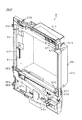
(内枠12の説明)
図10や図11に示すように、内枠12は、前扉体11と相似形をなす矩形状をなしており、概ね等しい細幅の左枠部101、右枠部102及び上枠部103と、それらよりも広幅の下枠部104とを有する。これら各枠部101〜104に囲まれる部位が中央開口部105となっており、内枠12の背面側には、下枠部104の上縁部の一部を除く範囲で中央開口部105を囲むようにして一定高さのリブ106が形成されている。ただし、左枠部101には軸金具111〜113が設けられており、その軸金具111〜113によって面替えブロック5や払出ブロック6が支持されることから、左枠部101のリブ106に関しては剛性を高めるべく比較的肉厚に形成されている。
(Description of inner frame 12)
As shown in FIGS. 10 and 11, the inner frame 12 has a rectangular shape that is similar to the front door body 11, and has a left frame portion 101, a right frame portion 102, and an upper frame portion 103 having substantially the same narrow width. And a lower frame portion 104 wider than them. A portion surrounded by each of the frame portions 101 to 104 is a central opening portion 105, and the central opening portion 105 is formed on the back side of the inner frame 12 within a range excluding a part of the upper edge portion of the lower frame portion 104. A rib 106 having a constant height is formed so as to surround it. However, the left frame portion 101 is provided with shaft fittings 111 to 113, and the surface changing block 5 and the payout block 6 are supported by the shaft fittings 111 to 113. It is formed relatively thick to increase the rigidity.
また、内枠12の前面側において、上枠部103には、前記中央ランプ部24の光源となるランプ類を実装したランプ基板107が取り付けられるとともに、その背面側に音声ランプ中継基板108が取り付けられている。
Further, on the front side of the inner frame 12, a lamp substrate 107 mounted with lamps serving as a light source of the central lamp unit 24 is attached to the upper frame portion 103, and an audio lamp relay substrate 108 is attached to the rear side thereof. It has been.
ここで、前扉体11に内枠12を組み付けた状態では、ランプ基板107は前扉体11の中央ランプ部24の後方に隠れるが、本実施の形態では特に、前扉体11の上側一部分を分離させて取り外し可能とし、その後方のランプ基板107やその他上部スピーカ92などのメンテナンス等を容易なものとしている。すなわち、図12に示すように、前扉体11の前面部は、中央ランプ部24及びスピーカ部26を含む範囲で分割されて構成されており、前扉体11(ドアブロック4)に対して分離可能な部位が上部カバー体94となっている。上部カバー体94を固定する固定手段としては、前扉体11及び内枠12に複数のネジ付け部109が設けられており、内枠12の後方よりネジ締結が行われるようになっている。実際には、上1カ所、左右2カ所ずつの計5カ所にネジ付け部109が設けられている。なお、図12の符号107aは、上部カバー体94を固定するための差込孔である。この差込孔107aをネジ締め付け孔として用いることも可能である。
Here, in a state where the inner frame 12 is assembled to the front door body 11, the lamp substrate 107 is hidden behind the central lamp portion 24 of the front door body 11, but in this embodiment, in particular, a part of the upper side of the front door body 11. The lamp board 107 and the upper speaker 92 behind the lamp board 107 can be easily maintained. That is, as shown in FIG. 12, the front portion of the front door body 11 is divided and configured in a range including the central lamp portion 24 and the speaker portion 26, with respect to the front door body 11 (door block 4). The separable part is the upper cover body 94. As a fixing means for fixing the upper cover body 94, a plurality of screwing portions 109 are provided on the front door body 11 and the inner frame 12, and screw fastening is performed from the rear of the inner frame 12. Actually, screwing portions 109 are provided at a total of five locations, one on the top and two on the left and right. Note that reference numeral 107 a in FIG. 12 is an insertion hole for fixing the upper cover body 94. It is also possible to use this insertion hole 107a as a screw tightening hole.
上部カバー体94において、中央ランプ部24には有色の透明又は半透明パネルが組み込まれており、当該パネルを通じてランプ基板107による発光が遊技機前方にて確認できるようになっている。また、スピーカ部26には多数のスリットが形成されており、このスリットを通じて上部スピーカ92による音声が遊技機前方にて確認できるようになっている。
In the upper cover body 94, a colored transparent or translucent panel is incorporated in the central lamp portion 24, and light emission from the lamp substrate 107 can be confirmed in front of the gaming machine through the panel. In addition, a large number of slits are formed in the speaker unit 26, and sound from the upper speaker 92 can be confirmed in front of the gaming machine through the slits.
本構成によれば、上部カバー体94を取り外すことにより、ランプ基板107や上部スピーカ92を露出させることができる。この場合、ドアブロック4を開放状態としたままでなくても、ランプ基板107上のランプ類や上部スピーカ92の修理や交換などを行うことができる。
According to this configuration, the lamp substrate 107 and the upper speaker 92 can be exposed by removing the upper cover body 94. In this case, the lamps on the lamp substrate 107 and the upper speaker 92 can be repaired or replaced without the door block 4 being left open.
前述したように本遊技機1は、正面から見て左側に回動軸線が設けられる構成となっており、上枠部103と下枠部104には前述のヒンジ金具8が上下2カ所に取り付けられている。このとき、前述した上部スピーカ92はヒンジ金具8の前方に位置し、上部スピーカ92は前寄りに設けられることとなる。かかる構成において、上部カバー体94が前外し可能であるため、上部スピーカ92のメンテナンスが容易となる。また、左右の上部スピーカ92が各々隅部に設けられているため、その間のランプ基板107(中央ランプ部24)が幅広に形成できるようになっている。更に、同じく左右の上部スピーカ92が各々隅部に設けられているため、視認窓21を拡大することができ、図柄等の表示領域を拡張することが可能となる。限られた領域内で各種の表示等を行う場合には、上記のような構成が有効であると考えられる。
As described above, the gaming machine 1 has a configuration in which the rotation axis is provided on the left side when viewed from the front, and the hinge bracket 8 is attached to the upper frame portion 103 and the lower frame portion 104 at two upper and lower positions. It has been. At this time, the above-described upper speaker 92 is positioned in front of the hinge fitting 8, and the upper speaker 92 is provided on the front side. In such a configuration, since the upper cover body 94 can be removed in front, maintenance of the upper speaker 92 is facilitated. Also, since the left and right upper speakers 92 are provided at the corners, the lamp substrate 107 (central lamp portion 24) between them can be formed wide. Furthermore, since the left and right upper speakers 92 are respectively provided at the corners, the viewing window 21 can be enlarged, and the display area for symbols and the like can be expanded. When various displays are performed in a limited area, the above configuration is considered to be effective.
左枠部101において、リブ106の先端部には上下3カ所に軸金具111,112,113が所定間隔を隔てて取り付けられている。これら軸金具111〜113は、面替えブロック5や払出ブロック6を回動可能に支持するための金具部材である。軸金具111〜113はいずれも略コ字状をなしており、軸金具111には上下に軸受け部111a,111bが形成され、軸金具112には上下に軸受け部112a,112bが形成され、軸金具113には上下に軸受け部113a,113bが形成されている。軸金具111〜113の各軸受け部111a,111b,112a,112b,113a,113bには軸孔が形成されており、軸金具111〜113は全ての軸孔が何れも同一の軸線上に配置されるようリブ106に固定されている。
In the left frame portion 101, shaft fittings 111, 112, and 113 are attached to the tip end portion of the rib 106 at three upper and lower portions at predetermined intervals. These shaft fittings 111 to 113 are fitting members for rotatably supporting the surface changing block 5 and the dispensing block 6. The shaft brackets 111 to 113 are all substantially U-shaped. The shaft bracket 111 has upper and lower bearing portions 111a and 111b, and the shaft bracket 112 has upper and lower bearing portions 112a and 112b. The metal fitting 113 is formed with bearing portions 113a and 113b in the vertical direction. A shaft hole is formed in each of the bearing portions 111a, 111b, 112a, 112b, 113a, and 113b of the shaft fittings 111 to 113, and all the shaft holes of the shaft fittings 111 to 113 are arranged on the same axis. It is being fixed to the rib 106 so that.
かかる場合、軸金具111の下側の軸受け部111bと軸金具112の上側の軸受け部112aとが面替えブロック5を支持するための面替えブロック支持手段に相当し、軸金具111の上側の軸受け部111aと軸金具112の下側の軸受け部112bと軸金具113の下側の軸受け部113bとが払出ブロック6を支持するための払出ブロック支持手段に相当する。
In such a case, the lower bearing portion 111b of the shaft bracket 111 and the upper bearing portion 112a of the shaft bracket 112 correspond to a surface changing block support means for supporting the surface changing block 5, and the bearing on the upper side of the shaft bracket 111. The portion 111 a, the lower bearing portion 112 b of the shaft fitting 112, and the lower bearing portion 113 b of the shaft fitting 113 correspond to a dispensing block support means for supporting the dispensing block 6.
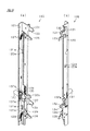
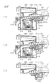
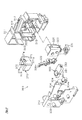
また、右枠部102には、ドアブロック4及び払出ブロック6を開放不能な施錠状態で保持するための施錠装置120が設けられている。図14は、施錠装置120の単体構成を示す斜視図であり、同図の(a),(b)は相対向する2方向から見た斜視図を示している。
Further, the right frame portion 102 is provided with a locking device 120 for holding the door block 4 and the payout block 6 in a locked state that cannot be opened. FIG. 14 is a perspective view showing a single structure of the locking device 120, and (a) and (b) of FIG. 14 are perspective views seen from two opposite directions.
図14において、施錠装置120は、金属板を折り曲げて成形された長尺状の基枠121を有しており、この基枠121が右枠部102の背面側に固定されることで、施錠装置120が内枠12に取り付け固定されるようになっている。基枠121の一面側(内枠12の外方となる側)には第1連動杆122が重なるようにして設けられるとともに、他面側(内枠12の内方となる側)には第2連動杆123が同じく重なるようにして設けられている。第1連動杆122には上下2カ所にスリット部122aが形成されており、そのスリット部122a内に、基枠121に設けたピン部材121aを配することにより、該スリット部122aの長さ分だけ第1連動杆122が上下方向に移動可能となっている。また、第2連動杆123には上下3カ所にスリット部123aが形成されており(ただし図示の角度の関係上、1カ所のスリット部123aのみを示す)、そのスリット部123a内に、基枠121に設けたピン部材121bを配することにより、該スリット部123aの長さ分だけ第2連動杆123が上下方向に移動可能となっている。
In FIG. 14, the locking device 120 has a long base frame 121 formed by bending a metal plate, and the base frame 121 is fixed to the back side of the right frame portion 102 to lock the base frame 121. The device 120 is attached and fixed to the inner frame 12. A first interlocking rod 122 is provided on one side of the base frame 121 (on the outer side of the inner frame 12) so as to overlap, and on the other side (on the inner side of the inner frame 12) Two interlocking rods 123 are also provided so as to overlap. The first interlocking rod 122 is formed with slit portions 122a at two upper and lower portions. By arranging a pin member 121a provided on the base frame 121 in the slit portion 122a, the length of the slit portion 122a is provided. Only the first interlocking rod 122 is movable in the vertical direction. The second interlocking rod 123 is formed with slit portions 123a at three locations in the upper and lower sides (however, only one slit portion 123a is shown because of the angle shown in the figure), and a base frame is formed in the slit portion 123a. By arranging the pin member 121b provided in 121, the second interlocking rod 123 can move in the vertical direction by the length of the slit portion 123a.
基枠121において第1連動杆122側には、鉤形状をなす上下一対の鉤金具125,126が設けられている。鉤金具125,126はその中間部分が基枠121に軸支されており、第1連動杆122が上方に移動することでその先端鉤部が下方に移動する構成となっている。鉤金具125,126の基端部(先端鉤部と反対側の部位)には、一端が基枠121に結合されたコイルバネ127,128が取り付けられており、コイルバネ127,128の付勢力によって、鉤金具125,126の基端部が下方に引き下げられるとともにそれと同時に第1連動杆122が下方に引き下げられ、図示する初期状態で保持されるようになっている。
In the base frame 121, a pair of upper and lower hook metal fittings 125, 126 having a hook shape are provided on the first interlocking rod 122 side. The intermediate portions of the metal fittings 125 and 126 are pivotally supported by the base frame 121, and the tip hook portion moves downward when the first interlocking rod 122 moves upward. Coil springs 127 and 128 each having one end coupled to the base frame 121 are attached to the base end portions (parts opposite to the front end hook portion) of the metal fittings 125 and 126, and by the biasing force of the coil springs 127 and 128, At the same time, the base end portions of the metal fittings 125 and 126 are pulled down, and at the same time, the first interlocking rod 122 is pulled down and held in the initial state shown in the drawing.
第1連動杆122には、下側の鉤金具126の上方に延出板部129が設けられている。この延出板部129は、鉤金具126の鉤凹部126aの真上でこの鉤凹部126aを塞ぐようにして設けられており、また外枠2に設けた鉤受け金具との位置関係で言えば該鉤受け金具の真上となる位置に延出板部129が設けられている。この場合、外枠2に対してドアブロック4が閉じた状態では、鉤金具126の鉤凹部126aに外枠2側の鉤受け金具が入った状態となっており、延出板部129が外枠2側の鉤受け金具に当たることによって、第1連動杆122の下方向への移動が阻害されるようになっている。
The first interlocking rod 122 is provided with an extending plate portion 129 above the lower metal fitting 126. The extension plate portion 129 is provided so as to close the flange recess 126a directly above the flange recess 126a of the flange fitting 126, and in terms of the positional relationship with the flange receiving bracket provided on the outer frame 2. An extending plate portion 129 is provided at a position directly above the flange receiving metal fitting. In this case, when the door block 4 is closed with respect to the outer frame 2, the hook receiving metal fitting on the outer frame 2 side is in the hook recess 126 a of the hook metal fitting 126, and the extension plate portion 129 is outside. The downward movement of the first interlocking rod 122 is inhibited by hitting the rod receiving bracket on the frame 2 side.
第2連動杆123には、鉤形状をなす上下一対の鉤金具部133,134が形成されている。また、基枠121には、第2連動杆123側に張り出しかつ第2連動杆123の鉤金具部133,134に重なるようにして上下一対の張出突片部131,132が形成されている。基枠121と第2連動杆123との間にはコイルバネ135が設けられており、コイルバネ135の付勢力によって、第2連動杆123が上方に引き上げられ、図示する初期状態で保持されるようになっている。
The second interlocking rod 123 is formed with a pair of upper and lower hook metal parts 133 and 134 having a hook shape. In addition, the base frame 121 is formed with a pair of upper and lower protruding protrusions 131 and 132 so as to protrude toward the second interlocking rod 123 and overlap the metal fittings 133 and 134 of the second interlocking rod 123. . A coil spring 135 is provided between the base frame 121 and the second interlocking rod 123 so that the second interlocking rod 123 is pulled upward by the biasing force of the coil spring 135 and is held in the initial state shown in the drawing. It has become.
かかる場合、図示する初期状態では、鉤金具部133,134の鉤凹部133a,134aの底側縁部が張出突片部131,132の上側縁部とほぼ同じ高さとなっており、鉤金具部133,134の先端鉤部のみが張出突片部131,132の上側縁部よりも上方に突き出た状態となっている。したがって、仮に、鉤金具部133,134による相手側部材(具体的には払出ブロック6)との結合を不正に解除する目的で、鉤凹部133a,134aにひもや針金などを引っ掛けて鉤金具部133,134を引き下げようとしても、張出突片部131,132によって、その引き下げが不可能となる。これにより、後述する払出ブロック6の不正開放が抑止されるようになっている。
In this case, in the initial state shown in the figure, the bottom side edges of the flange recesses 133a, 134a of the metal fitting parts 133, 134 are substantially the same height as the upper edge parts of the protruding protrusions 131, 132, Only the distal end flanges of the portions 133 and 134 are in a state of protruding upward from the upper edge portions of the protruding protrusions 131 and 132. Therefore, for the purpose of illegally releasing the coupling of the metal fitting parts 133 and 134 with the mating member (specifically, the payout block 6), the metal fitting parts are hooked with hooks or wires on the metal depressions 133a and 134a. Even if it is going to pull down 133,134, it cannot be pulled down by the protruding protrusions 131,132. As a result, unauthorized opening of the payout block 6 described later is prevented.
下側の張出突片部132には、下側の鉤金具部134の上方に延出板部132aが設けられている。この延出板部132aは、鉤金具部134の鉤凹部134aの真上でこの鉤凹部134aを塞ぐようにして設けられており、この延出板部132aによって、鉤凹部134a内に鉤受け部材(具体的には払出ブロック6側の鉤受け部)が拘束された状態においてその鉤受け部材が容易に外れないようになっている。
An extension plate portion 132 a is provided on the lower protruding projecting portion 132 above the lower metal fitting portion 134. The extension plate portion 132a is provided so as to close the flange recess portion 134a just above the flange recess portion 134a of the metal fitting portion 134, and the extension plate portion 132a allows the hook receiving member to be placed in the flange recess portion 134a. In a state where the hook receiving portion (specifically, the hook receiving portion on the payout block 6 side) is restrained, the hook receiving member is not easily detached.
基枠121には、解錠操作部たるキーシリンダ137が設けられている。このキーシリンダ137は前後方向に延びる向きで設けられており、前扉体11に内枠12を組み付けた際にはシリンダ前面(キー挿入孔の設置側)が前扉体11に設けたキーシリンダ設置穴62から露出することとなる。なお、キーシリンダ137として、不正解錠防止機能の高いオムロック(登録商標)を用いる構成としても良い。
The base frame 121 is provided with a key cylinder 137 as an unlocking operation unit. The key cylinder 137 is provided so as to extend in the front-rear direction. When the inner frame 12 is assembled to the front door body 11, the front surface of the cylinder (the side where the key insertion hole is installed) is provided on the front door body 11. It will be exposed from the installation hole 62. The key cylinder 137 may be configured to use Omlock (registered trademark) having a high function of preventing unauthorized unlocking.
次に、操作キーの回動操作に伴う施錠装置120の動作について図15及び図16を用いて説明する。図15は、操作キーの回動操作により第1連動杆122を上動させ、それに伴い鉤金具125,126を係止解除状態とする状態を示している。また、図16は、同じく操作キーの回動操作により第2連動杆123を下動させ、それに伴い鉤金具部133,134を係止解除状態とする状態を示している。
Next, the operation of the locking device 120 accompanying the rotation operation of the operation key will be described with reference to FIGS. 15 and 16. FIG. 15 shows a state in which the first interlocking rod 122 is moved upward by the rotation operation of the operation key, and accordingly, the metal fittings 125 and 126 are brought into the unlocked state. FIG. 16 also shows a state where the second interlocking rod 123 is moved downward by the rotation operation of the operation key, and the hook metal parts 133 and 134 are brought into the unlocked state accordingly.
図15では、操作キー(図示略)をキーシリンダ137に差し込んで時計回り方向に回動操作している。すると、キーシリンダ137の回動操作に連動する下側の爪片137aにより、コイルバネ127,128の付勢力に抗して第1連動杆122が上方に移動し、それに伴い鉤金具125,126の先端鉤部が下方に移動する。かかる場合、本遊技機1においては、外枠2に対してドアブロック4が閉じている状態で、鉤金具125,126と外枠2側の鉤受け金具との係止状態(すなわち施錠状態)が解除され、これにより、外枠2に対してドアブロック4が開放可能となる。その後、操作キーの回動操作を解除すると、コイルバネ127,128の付勢力により第1連動杆122や鉤金具125,126が初期状態に復帰する。
In FIG. 15, an operation key (not shown) is inserted into the key cylinder 137 and rotated in the clockwise direction. Then, the first claw 122 moves upward against the urging force of the coil springs 127 and 128 by the lower claw piece 137a that is interlocked with the rotation operation of the key cylinder 137, and accordingly, the metal fittings 125 and 126 The tip collar moves downward. In such a case, in the gaming machine 1, when the door block 4 is closed with respect to the outer frame 2, the hook metal 125, 126 and the hook receiving metal on the outer frame 2 side are locked (that is, locked). Thus, the door block 4 can be opened with respect to the outer frame 2. Thereafter, when the rotation operation of the operation key is released, the first interlocking rod 122 and the metal fittings 125, 126 are returned to the initial state by the urging force of the coil springs 127, 128.
一方、図16では、操作キー(図示略)をキーシリンダ137に差し込んで反時計回り方向に回動操作している。すると、キーシリンダ137の回動操作に連動する上側の爪片137bにより、コイルバネ135の付勢力に抗して第1連動杆122及び第2連動杆123が下方に移動し、それに伴い鉤金具部133,134が下方に移動する。かかる場合、本遊技機1においては、ドアブロック4に対して払出ブロック6が閉じている状態で、鉤金具部133,134と払出ブロック6側の鉤受け部との係止状態(すなわち施錠状態)が解除される。そして、ドアブロック4に対して払出ブロック6が開放可能となる。その後、操作キーの回動操作を解除すると、コイルバネ135の付勢力により第2連動杆123が初期状態に復帰する。
On the other hand, in FIG. 16, an operation key (not shown) is inserted into the key cylinder 137 and rotated counterclockwise. Then, the upper claw piece 137b interlocked with the turning operation of the key cylinder 137 moves the first interlocking rod 122 and the second interlocking rod 123 downward against the urging force of the coil spring 135, and accordingly, the metal fitting portion 133 and 134 move downward. In such a case, in the gaming machine 1, when the payout block 6 is closed with respect to the door block 4, the hook metal parts 133, 134 and the hook receiving part on the payout block 6 side are locked (that is, locked). ) Is canceled. Then, the payout block 6 can be opened with respect to the door block 4. Thereafter, when the rotation operation of the operation key is released, the second interlocking rod 123 returns to the initial state by the biasing force of the coil spring 135.
なお、外枠2に対してドアブロック4が閉じた状態では、鉤金具126の鉤凹部126aに外枠2側の鉤受け金具が入った状態となっており、外枠2側の鉤受け金具によって、第1連動杆122の下方向の移動が阻害される。これにより、鉤金具部133,134と払出ブロック6側の鉤受け部との係止状態(すなわち施錠状態)が解除できないようになっている。
When the door block 4 is closed with respect to the outer frame 2, the hook receiving metal fitting on the outer frame 2 side is in the hook recess 126 a of the metal fitting 126, and the hook receiving metal fitting on the outer frame 2 side. Accordingly, the downward movement of the first interlocking rod 122 is inhibited. As a result, the locked state (that is, the locked state) between the hook metal parts 133 and 134 and the hook receiving part on the payout block 6 side cannot be released.
図11に示すように、下枠部104には、取込ユニット16を収容するための取込ユニット収容部141が形成されている。この取込ユニット収容部141は、取込ユニット16を載置した状態で、その奥側(遊技機1で言えば前側)及び左右両側を囲むようにして保持するユニット保持部である。また、取込ユニット収容部141の上方には、図13に示すように、上皿ユニット15が配置されている。つまり、取込ユニット16の上部は上皿ユニット15により覆われ、取込ユニット16のドアブロック4への取り付けは上皿ユニット16と取込ユニット収容部141とにより仕切られた後方開口部に対して前後方向にスライド移動させることにより行われる。なお、取込ユニット16はボス304を備えており、ボス304に設けられた挿通孔304aを介してビス149が挿通されドアブロック4に対する固定が行われている。
As shown in FIG. 11, the lower frame portion 104 is formed with an intake unit accommodating portion 141 for accommodating the intake unit 16. The take-in unit accommodating portion 141 is a unit holding portion that holds the take-in unit 16 so as to surround the back side (the front side in the case of the gaming machine 1) and the left and right sides. Further, as shown in FIG. 13, an upper plate unit 15 is disposed above the take-in unit accommodating portion 141. That is, the upper part of the take-in unit 16 is covered with the upper plate unit 15, and the attachment of the take-in unit 16 to the door block 4 is performed with respect to the rear opening portion partitioned by the upper plate unit 16 and the take-in unit accommodating portion 141. This is done by sliding it back and forth. The take-in unit 16 includes a boss 304, and a screw 149 is inserted through an insertion hole 304 a provided in the boss 304 and is fixed to the door block 4.
取込ユニット収容部141の底部には、取込ユニット16にて取り込まれた遊技球を排出するための球排出室142が形成されており、球排出室142に回収された遊技球は図示しない排出通路を介して遊技機外部(遊技ホールの島設備など)に排出されようになっている。また、取込ユニット収容部141の左方(背面側から見て左方)には、取込ユニット16に一旦は導かれそれ後下皿71に排出される遊技球(すなわち、遊技者に返還される遊技球)を通過させるための排出通路143が形成されており、この排出通路143に流れ込む遊技球は、内枠12の前面側に開口する開口部144及び前扉体11の下皿排出口74を経由して下皿71に排出されるようになっている。また、取込ユニット収容部141の右方(背面側から見て右方)には、下皿71に通じる下皿連通路145が形成されており、この下皿連通路145に流れ込む遊技球は、前記排出通路143に流れ込む遊技球と同様、内枠12の開口部144及び前扉体11の下皿排出口74を経由して下皿71に排出されるようになっている。
A ball discharge chamber 142 for discharging game balls taken in by the take-in unit 16 is formed at the bottom of the take-in unit accommodating portion 141, and the game balls collected in the ball discharge chamber 142 are not shown. It is discharged to the outside of the gaming machine (such as island facilities in the gaming hall) through the discharge passage. Further, on the left side (left side when viewed from the back side) of the take-in unit accommodating portion 141, a game ball that is once guided to the take-in unit 16 and then discharged to the lower plate 71 (that is, returned to the player). A discharge passage 143 for allowing a game ball to pass therethrough is formed, and the game ball flowing into the discharge passage 143 has an opening 144 opened on the front side of the inner frame 12 and a lower pan discharge of the front door body 11. It is discharged to the lower plate 71 via the outlet 74. Further, a lower plate communication path 145 leading to the lower plate 71 is formed on the right side (right side when viewed from the back side) of the take-in unit accommodating portion 141, and the game balls flowing into the lower plate communication path 145 are Similarly to the game ball flowing into the discharge passage 143, the game ball is discharged to the lower plate 71 through the opening 144 of the inner frame 12 and the lower plate discharge port 74 of the front door body 11.
下枠部104にはスピーカ146が設けられている。スピーカ146は、前記前扉体11のスピーカ穴75から前方に露出し、これにより音声が前方に発せられる。
The lower frame portion 104 is provided with a speaker 146. The speaker 146 is exposed forward from the speaker hole 75 of the front door body 11, and thereby the sound is emitted forward.
内枠12の背面側において、その右上隅部とスピーカ146の側方部には、ドアブロック4の背面側に取り付けられる払出ブロック6を固定するための固定手段として鉤金具147,148が設けられている。
On the back side of the inner frame 12, metal fittings 147 and 148 are provided as fixing means for fixing the payout block 6 attached to the back side of the door block 4 at the upper right corner and the side of the speaker 146. ing.
(上皿ユニット15の説明)
次に、上皿ユニット15について説明する。図17は上皿ユニット15の斜視図、図18は上皿ユニット15の平面図((a)は上方から見た平面図、(b)は下方から見た平面図)、図19は上皿ユニット15の分解斜視図である。
(Description of the upper plate unit 15)
Next, the upper plate unit 15 will be described. 17 is a perspective view of the upper plate unit 15, FIG. 18 is a plan view of the upper plate unit 15 ((a) is a plan view seen from above, (b) is a plan view seen from below), and FIG. 19 is an upper plate. 3 is an exploded perspective view of a unit 15. FIG.
上皿ユニット15は、遊技に際し順次取り込まれる遊技球を一時的に貯留する機能を有する上皿151を有しており、その上皿151の上面側には、球出口部付近を覆うカバー部材152が取り付けられ、さらに該上皿151の一部を覆うようにして横長薄板状の上覆い板157が取り付けられている。また、上皿151の下面側には貸球操作装置153と排出操作伝達装置154と球留め装置155とが取り付けられている。
The upper plate unit 15 has an upper plate 151 having a function of temporarily storing game balls that are sequentially taken in during the game, and a cover member 152 that covers the vicinity of the ball outlet portion on the upper surface side of the upper plate 151. And a horizontally long thin plate-like upper cover plate 157 is attached so as to cover a part of the upper plate 151. A ball rental operating device 153, a discharge operation transmitting device 154, and a ball retaining device 155 are attached to the lower surface side of the upper plate 151.
図18の(a)に示すように、上皿ユニット15の上面側では、上皿151の半分近くの領域が上覆い板157にて覆われ、さらにこの上覆い板157によってカバー部材152の約半分が覆われている。また、図18の(b)に示すように、上皿ユニット15の下面側では、貸球操作装置153と排出操作伝達装置154とが上下に重なるようにして配設されるとともに、これら貸球操作装置153及び排出操作伝達装置154の後方側(図では下側)に球留め装置155が配設されている。
As shown in FIG. 18A, on the upper surface side of the upper plate unit 15, an area near half of the upper plate 151 is covered with the upper cover plate 157, and the upper cover plate 157 further reduces the cover member 152. Half covered. Further, as shown in FIG. 18 (b), on the lower surface side of the upper plate unit 15, the lending operation device 153 and the discharge operation transmitting device 154 are arranged so as to overlap each other. A ball retainer 155 is disposed on the rear side (lower side in the figure) of the operation device 153 and the discharge operation transmission device 154.
(上皿151の説明)
次に、上皿151の構成について説明する。図20は上皿151の斜視図であり、図21は上皿151の平面図である。また、図22は、上皿151に貸球操作装置153を設置するとともにカバー部材152を分離した状態を示す斜視図である。
(Description of the upper plate 151)
Next, the configuration of the upper plate 151 will be described. FIG. 20 is a perspective view of the upper plate 151, and FIG. 21 is a plan view of the upper plate 151. FIG. 22 is a perspective view showing a state where the ball rental operating device 153 is installed on the upper plate 151 and the cover member 152 is separated.
上皿151は、島設備の球貸し装置から貸し出された遊技球や、払出装置より払い出された遊技球を一旦貯留するための受け皿部材を構成するものであり、底板部161とその周縁部を囲む周壁部162とにより横長の樋状に成形されている。これら底板部161と周壁部162とにより囲まれて遊技球貯留領域が形成されている。周壁部162のうち奥側の壁部には、正面から見て左側の位置に排出口163が設けられている。また、底板部161には、正面から見て右側の位置に開口部164が設けられている。本上皿151では、底板部161が概して排出口163から開口部164に向けて低くなる構成となっており、排出口163から遊技球が排出されるとその遊技球は図21の左側から右側に向けて流れるようになっている。
The upper plate 151 constitutes a tray member for temporarily storing game balls lent out from the ball lending device of the island facility or game balls paid out from the payout device. The bottom plate portion 161 and its peripheral portion Is formed into a horizontally long bowl shape. A game ball storage area is formed by being surrounded by the bottom plate portion 161 and the peripheral wall portion 162. A discharge port 163 is provided in a wall portion on the back side of the peripheral wall portion 162 at a position on the left side when viewed from the front. In addition, the bottom plate portion 161 is provided with an opening 164 at a position on the right side when viewed from the front. In the upper plate 151, the bottom plate 161 is generally lowered from the discharge port 163 toward the opening 164. When a game ball is discharged from the discharge port 163, the game ball is moved from the left side to the right side in FIG. It is designed to flow toward
周壁部162のうち手前側の壁部には、奥側に凹んだ形状をなす凹部165が形成されており、その凹部165により、本上皿ユニット15を前扉体11に組み付けた際においてベットスイッチ取付板部32と上皿151との干渉が回避されるようになっている。
A concave portion 165 having a concave shape on the back side is formed in the front wall portion of the peripheral wall portion 162, and when the upper plate unit 15 is assembled to the front door body 11 by the concave portion 165, Interference between the switch mounting plate 32 and the upper plate 151 is avoided.
上皿151の最下流部には、底板部161より隆起した2つの仕切部167,168が設けられており、この仕切部167,168に仕切られることで三列の案内通路171,172,173が形成されている。これら各案内通路171〜173は、前記開口部164に通ずるように設けられており、遊技球を各一列に整列するための整列通路部を構成する。
Two partition portions 167 and 168 that protrude from the bottom plate portion 161 are provided at the most downstream portion of the upper plate 151, and the three guide passages 171, 172, and 173 are partitioned by the partition portions 167 and 168. Is formed. Each of these guide passages 171 to 173 is provided so as to communicate with the opening 164, and constitutes an alignment passage portion for aligning the game balls in each row.
三列の案内通路171〜173の手前側には、貸球操作装置153等を設置するための貸球操作装置設置部175が設けられている。貸球操作装置設置部175には、左右2つの円形凹部176,177と矩形状の窓部178とが形成されている。
On the front side of the three rows of guide passages 171 to 173, a ball rental operating device installation unit 175 for installing the ball rental operating device 153 and the like is provided. The ball lending operation device installation portion 175 is formed with two left and right circular concave portions 176 and 177 and a rectangular window portion 178.
図19に示すように、貸球操作装置153は、操作装置基板181と、その操作装置基板181を設置するための台板182とを備えており、台板182上に操作装置基板181を設置することにより、貸球操作装置153が構成されている。
As shown in FIG. 19, the rental ball operating device 153 includes an operating device substrate 181 and a base plate 182 for installing the operating device substrate 181. The operating device substrate 181 is installed on the base plate 182. As a result, a ball rental operating device 153 is configured.
ここで、貸球操作装置153は、例えば本遊技機1の側方(例えば左方)に配置された縦長のカードユニット(球貸しユニット)に紙幣やカード等を投入した状態で、球貸し操作、カード等の返却操作及び有効度数の確認を行うものであり、操作装置基板181上には、球貸しボタン183と返却ボタン184と度数表示部185とが一体的に並設されている。この場合、球貸しボタン183は、カード(記録媒体)等に記録された情報に基づいて貸出球を得るために操作されるものであり、カード等に残額が存在する限りにおいて貸出球が払い出される。返却ボタン184は、カードユニットに挿入されたカード等の返却を求める際に操作される。度数表示部185にはカードの残額情報や投入金額などが表示される。
Here, the ball lending operation device 153 performs the ball lending operation in a state where, for example, bills or cards are inserted into a vertically long card unit (ball lending unit) arranged on the side (for example, the left side) of the gaming machine 1. The card return operation and the effective frequency are confirmed. A ball lending button 183, a return button 184, and a frequency display unit 185 are integrally arranged in parallel on the operation device substrate 181. In this case, the ball lending button 183 is operated to obtain a lending ball based on information recorded on a card (recording medium) or the like, and the lending ball is paid out as long as the remaining amount exists on the card or the like. . The return button 184 is operated when requesting the return of a card or the like inserted into the card unit. The frequency display portion 185 displays the remaining amount information of the card, the amount of money inserted, and the like.
貸球操作装置設置部175に貸球操作装置153を設置した状態では、図22に示すように、貸球操作装置設置部175の窓部178から度数表示部185が視認できるようになる。図22では、貸球操作装置設置部175の円形凹部176,177に各々半球状をなす押しボタン部材186,187を取り付けた状態を示しており、押しボタン部材186,187が押し操作されることにより間接的に球貸しボタン183や返却ボタン184が押され、それに伴い遊技球の貸し出しやカード等の返却などが適宜実施されるようになっている。
In a state where the ball rental operation device 153 is installed in the ball rental operation device installation unit 175, the frequency display unit 185 can be visually recognized from the window 178 of the ball rental operation device installation unit 175, as shown in FIG. FIG. 22 shows a state where push button members 186 and 187 each having a hemispherical shape are attached to the circular concave portions 176 and 177 of the ball lending operation device installation portion 175, and the push button members 186 and 187 are pushed. Accordingly, the ball lending button 183 and the return button 184 are indirectly pressed, and accordingly, the lending of game balls, the return of cards and the like are appropriately performed.
図19に示すように、カバー部材152は、カバー本体188と、該カバー本体188の下面側に重ねて組み付けられる下カバー体189とにより構成されている。これらカバー本体188及び下カバー体189はいずれも透明の合成樹脂材料にて成形されている。カバー本体188及び下カバー体189にはそれぞれ円形の孔部188a,189aが形成されており、これら両部材を重ね合わせた状態でカバー部材152を上皿151に装着すると、各孔部188a,189aを介して押しボタン部材186,187が露出する。これにより、押しボタン部材186,187の押し操作が可能となっている。また、カバー本体188及び下カバー体189は各々透明体にて構成されているため、度数表示部185上にカバー部材152が被せられてもその度数表示等が視認可能となっている。なお、符号190は、カバー部材152を上皿151に固定するための固定フック部である。
As shown in FIG. 19, the cover member 152 includes a cover main body 188 and a lower cover body 189 that is assembled on the lower surface side of the cover main body 188. Both the cover main body 188 and the lower cover body 189 are formed of a transparent synthetic resin material. Circular holes 188a and 189a are formed in the cover main body 188 and the lower cover body 189, respectively. When the cover member 152 is attached to the upper plate 151 in a state where these two members are overlapped with each other, the holes 188a and 189a are provided. The push button members 186 and 187 are exposed through the. Thereby, the push operation of the push button members 186 and 187 is possible. Further, since the cover main body 188 and the lower cover body 189 are each formed of a transparent body, even if the cover member 152 is put on the frequency display portion 185, the frequency display and the like can be visually recognized. Reference numeral 190 denotes a fixing hook portion for fixing the cover member 152 to the upper plate 151.
カバー部材152は、開口部164と各案内通路171〜173の一部と貸球操作装置設置部175とを上方から覆うようにして上皿151に取り付けられ、その際、カバー部材152は、各案内通路171〜173の高さ方向の寸法を概ね遊技球1個分に規制するための通路高さ規制部材としても機能する。すなわち、カバー部材152を上皿151に取り付けることにより、各案内通路171〜173において遊技球が1つずつ取り込まれるようになる。このとき、カバー部材152が透明体にて構成されているため、その下方の遊技球(各案内通路171〜173を通過する遊技球)が視認可能となっている。
The cover member 152 is attached to the upper plate 151 so as to cover the opening 164, a part of each of the guide passages 171 to 173 and the rental ball operating device installation unit 175 from above, and at that time, the cover member 152 The guide passages 171 to 173 also function as passage height regulating members for regulating the dimension in the height direction to approximately one game ball. That is, by attaching the cover member 152 to the upper plate 151, one game ball is taken in each of the guide passages 171 to 173. At this time, since the cover member 152 is made of a transparent body, the lower game balls (game balls passing through the guide passages 171 to 173) are visible.
上皿151には、上述したように上覆い板157が取り付けられている。この場合、上覆い板157によれば、上皿151の奥側一部に上蓋が設けられるようになる(図17等参照)。この上覆い板157による上皿151の被蓋部分は、上皿ユニット15をドアブロック4に装着した状態で上皿151がドアブロック4の内部に隠れる部位に相当している。つまり、上皿ユニット15をドアブロック4に装着した状態では、ドアブロック4(前扉体11)に設けられた開口部41の前後方向の幅寸法(A)と上皿151の前後方向の幅寸法(B)とがA<Bであるため(A,Bは左右方向の同一箇所での寸法比較)、上皿151の奥側一部がドアブロック4の内側に没入することとなる。この場合、上皿151においてドアブロック4内側に没入した部位が上方に開放されたままであると、上皿151の手前側から奥側に入れた指や不正工具等が上皿奥側の上方開放部分を通じて遊技機内部に差し入れられ、その遊技機内部において不正行為などが行われるといった不都合が懸念される。この点、上記のとおり上覆い板157が設けられることにより、指や不正工具等を上皿151を通じて遊技機内部に差し入れることによる不正行為が抑制できる。要するに、上覆い板157は、上皿151と遊技機内部の空間(ドアブロック4の内側領域)との間を遮蔽する遮蔽部材となっている。
The upper cover plate 157 is attached to the upper plate 151 as described above. In this case, according to the upper cover plate 157, an upper lid is provided on a part of the back side of the upper plate 151 (see FIG. 17 and the like). The covered portion of the upper plate 151 by the upper cover plate 157 corresponds to a portion where the upper plate 151 is hidden inside the door block 4 when the upper plate unit 15 is mounted on the door block 4. That is, in the state where the upper plate unit 15 is mounted on the door block 4, the width dimension (A) in the front-rear direction of the opening 41 provided in the door block 4 (front door body 11) and the width in the front-rear direction of the upper plate 151. Since the dimension (B) is A <B (A and B are dimension comparisons at the same place in the left-right direction), a part of the back side of the upper plate 151 is immersed inside the door block 4. In this case, if the portion of the upper plate 151 that has entered the inside of the door block 4 remains open upward, fingers or unauthorized tools placed from the front side of the upper plate 151 to the back side will open upward on the back side of the upper plate 151. There is a concern that it will be inserted into the gaming machine through the part and illegal activities will be performed inside the gaming machine. In this regard, by providing the upper cover plate 157 as described above, it is possible to suppress an illegal act caused by inserting a finger, an unauthorized tool, or the like into the gaming machine through the upper plate 151. In short, the upper cover plate 157 is a shielding member that shields between the upper plate 151 and the space inside the gaming machine (the inner region of the door block 4).
なお、上覆い板157は透明板で構成される。したがって、上皿151の一部が上覆い板157で隠されたとしても上皿151の内部確認(汚れや破損等の確認を含む)が容易となる。
The upper cover plate 157 is made of a transparent plate. Therefore, even if a part of the upper plate 151 is hidden by the upper cover plate 157, it is easy to confirm the inside of the upper plate 151 (including confirmation of dirt, damage, etc.).
(排出操作伝達装置154の説明)
次に、排出操作伝達装置154について説明する。この排出操作伝達装置154は、後述する取込ユニット16の排出ゲート部材340を操作して上皿151内の貯留球を下皿71に排出するための球抜き操作装置であり、その詳細な構成を図23及び図24に示す。
(Description of discharge operation transmission device 154)
Next, the discharge operation transmission device 154 will be described. This discharge operation transmission device 154 is a ball removal operation device for operating a discharge gate member 340 of the take-in unit 16 described later to discharge the stored balls in the upper plate 151 to the lower plate 71, and its detailed configuration Are shown in FIGS.
図23及び図24に示すように、排出操作伝達装置154において、ケース体191には2つの軸部192,193が設けられており、その軸部192,193にはそれぞれ第1リンク片194と第2リンク片195とが回動可能に支持されている。これら第1,第2リンク片194,195は各々の一部分が互いに連結されており、第1リンク片194に連動して第2リンク片195が回動する。第1リンク片194には引張バネ196が設けられており、第1リンク片194は引張バネ196のバネ力により常に同方向(図では反時計回り方向)に付勢されている。また、ケース体191の手前側端面には、左右方向に移動可能な操作レバー198が設けられており、この操作レバー198に一体に設けられた支柱部198aが第1リンク片194に設けられた孔部194aに挿通されている。故に、操作レバー198のスライド操作に伴い第1リンク片194が軸部192を中心に回動する。
As shown in FIGS. 23 and 24, in the discharge operation transmission device 154, the case body 191 is provided with two shaft portions 192 and 193, and the shaft portions 192 and 193 have first link pieces 194 and 194, respectively. A second link piece 195 is rotatably supported. The first and second link pieces 194 and 195 are partially connected to each other, and the second link piece 195 rotates in conjunction with the first link piece 194. The first link piece 194 is provided with a tension spring 196, and the first link piece 194 is always biased in the same direction (counterclockwise direction in the figure) by the spring force of the tension spring 196. In addition, an operation lever 198 that is movable in the left-right direction is provided on the front side end surface of the case body 191, and a support column 198 a provided integrally with the operation lever 198 is provided on the first link piece 194. It is inserted through the hole 194a. Therefore, the first link piece 194 rotates around the shaft portion 192 as the operating lever 198 is slid.
上記構成の排出操作伝達装置154では、遊技者等により操作レバー198が図示の位置から左方(図24のP1方向)にスライド操作されることにより、第1リンク片194が引張バネ196のバネ力に抗して図の時計回り方向(図24のP2方向)に回動するとともに、第2リンク片195が反時計回り方向に回動(図24のP3方向)する。これにより、第2リンク片195の回動先端部が後方側(図24のP4方向)へと移動する。また、操作レバー198の操作が解除されると、引張バネ196のバネ力により第1リンク片194が図の反時計回り方向に回動するとともに、第2リンク片195が時計回り方向に回動する。これにより、排出操作伝達装置154が元の状態に復帰する。こうした排出操作伝達装置154の動作により、後述する取込ユニット16の排出ゲート部材340が操作され、取込ユニット16を介しての遊技球の排出(実際には遊技球の下皿71への排出)が行われるようになっている。
In the discharging operation transmission device 154 configured as described above, the first link piece 194 is a spring of the tension spring 196 when the player or the like slides the operation lever 198 to the left (P1 direction in FIG. 24). The second link piece 195 rotates counterclockwise (P3 direction in FIG. 24) while rotating in the clockwise direction (P2 direction in FIG. 24) against the force. Thereby, the rotation front-end | tip part of the 2nd link piece 195 moves to the back side (P4 direction of FIG. 24). When the operation lever 198 is released, the first link piece 194 is rotated counterclockwise by the spring force of the tension spring 196 and the second link piece 195 is rotated clockwise. To do. Thereby, the discharge operation transmission device 154 returns to the original state. By such an operation of the discharge operation transmission device 154, a discharge gate member 340 of the take-in unit 16 described later is operated, and game balls are discharged through the take-in unit 16 (actually, the game balls are discharged to the lower plate 71). ) Is to be performed.
(球留め装置155の説明)
次に、球留め装置155について説明する。この球留め装置155は、上皿151の下方に設置される取込ユニット16が取り外された際において上皿151から遊技球がこぼれ落ちるのを防止するための遊技球落下防止装置であり、その詳細な構成を以下に説明する。図25は球留め装置155の分解斜視図、図26は球留め装置155の単体構成を示す平面図、図27は取込ユニット16を上皿151下方に装着した状態及び分離させた状態を後方側から示す背面図である。なお、球留め装置155の動作状態として、図26の(a)と図27の(a)とが対応し、図26の(b)と図27の(b)とが対応している。
(Description of the ball stopper device 155)
Next, the ball retainer 155 will be described. This ball stopper device 155 is a game ball fall prevention device for preventing a game ball from spilling down from the upper plate 151 when the take-in unit 16 installed below the upper plate 151 is removed. A detailed configuration will be described below. 25 is an exploded perspective view of the ball-clamping device 155, FIG. 26 is a plan view showing a single unit configuration of the ball-clamping device 155, and FIG. 27 is a rear view showing a state where the take-in unit 16 is mounted below and separated from the upper plate 151. It is a rear view shown from the side. In addition, as an operation state of the ball stopper device 155, FIG. 26 (a) corresponds to FIG. 27 (a), and FIG. 26 (b) corresponds to FIG. 27 (b).
球留め装置155は、上皿151の下面に固定される本体部211と、該本体部211上に載置され図26の左右方向に往復動可能な可動部212と、可動部212を同左右方向に往復動させるべく回動操作される操作バー213とを有している。そして、この球留め装置155は、操作バー213が遊技機後方になるようにして上皿151に組み付けられている。
The ball retainer 155 includes a main body 211 fixed to the lower surface of the upper plate 151, a movable part 212 mounted on the main body 211 and capable of reciprocating in the left-right direction in FIG. And an operation bar 213 that is rotated to reciprocate in the direction. And this ball-clamping device 155 is assembled to the upper plate 151 so that the operation bar 213 is located behind the gaming machine.
可動部212には、同一方向に並ぶようにして3つのアーム部214,215,216が形成されている。各アーム部214〜216はそれぞれ二股に分岐されており、その先端には上方(図26では紙面手前側)に折れ曲がるようにして起立する各2個ずつの起立部217,218,219が形成されている。可動部212に形成された各アーム部214〜216の間隔は、前記上皿151に形成した3つの案内通路171〜173に合致しており、各アーム部214〜216の起立部217〜219は、上皿151の各案内通路171〜173に通じる開口部164から現出するようになっている。また、可動部212の下面側には、操作バー213と同方向に延びる溝部220が形成されている。
Three arms 214, 215, and 216 are formed on the movable portion 212 so as to be aligned in the same direction. Each of the arm portions 214 to 216 is bifurcated, and two rising portions 217, 218, and 219 are formed at the tip of the arm portions 214 to 216 so as to be bent upward (front side in FIG. 26). ing. The intervals between the arm portions 214 to 216 formed in the movable portion 212 are matched with the three guide passages 171 to 173 formed in the upper plate 151, and the standing portions 217 to 219 of the arm portions 214 to 216 are The upper plate 151 emerges from the opening 164 leading to the guide passages 171 to 173. Further, a groove portion 220 extending in the same direction as the operation bar 213 is formed on the lower surface side of the movable portion 212.
操作バー213は、その軸部221が溝部220内に収容された状態で本体部211に支持されている。操作バー213はこの軸部221を軸心として回動可能となっており、軸部221にはその軸心から径方向に延びる一対の突起片222a,222bが3組形成されている。対をなす突起片222a,222bはその延出方向が互いに略直交しており、軸部221の直径と突起片222a又は突起片222bの長さとを合わせた寸法は、溝部220の左右方向の幅と略同一となっている。この場合、図26の(a),図27の(a)の状態では一方の突起片222aの先端が溝部220の内壁に当たり、操作バー213の回動によって図26の(b),図27の(b)の状態に移行すると、他方の突起片222bの先端が溝部220の内壁に当たることとなる(便宜上、図26,図27では突起片222a,222bに点ハッチを付している)。これにより、可動部212が左右方向に移動する。図26で言えば、可動部212の左右方向の移動によって、可動部212の各アーム部214〜216の先端突出量が(a),(b)で変化する。(a)では先端突出量=L1であるのに対し、(b)では先端突出量=L2となっている(L1<L2)。
The operation bar 213 is supported by the main body 211 in a state where the shaft 221 is accommodated in the groove 220. The operation bar 213 is rotatable about the shaft portion 221 as an axis, and the shaft portion 221 is formed with three pairs of protruding pieces 222a and 222b extending from the shaft center in the radial direction. The extending directions of the pair of protruding pieces 222a and 222b are substantially orthogonal to each other, and the combined length of the diameter of the shaft portion 221 and the length of the protruding piece 222a or the protruding piece 222b is the width of the groove portion 220 in the horizontal direction. It is almost the same. In this case, in the state of FIGS. 26A and 27A, the tip of one projection piece 222a hits the inner wall of the groove 220, and the operation bar 213 rotates to rotate the operation bar 213 as shown in FIGS. When the state shifts to the state (b), the tip of the other protrusion 222b comes into contact with the inner wall of the groove 220 (for convenience, the protrusions 222a and 222b are hatched in FIGS. 26 and 27). As a result, the movable portion 212 moves in the left-right direction. In FIG. 26, the amount of protrusion of the tip of each arm part 214 to 216 of the movable part 212 changes in (a) and (b) by the movement of the movable part 212 in the left-right direction. In (a), the tip protrusion amount = L1, whereas in (b), the tip protrusion amount = L2 (L1 <L2).
操作バー213には、その先端に遊技機後方側に突出した操作つまみ213aが一体形成されている。操作つまみ213aは長手形状に形成されており、操作バー213の回動操作に伴い長手方向の向きが変化する。なお、操作つまみ213aは略十字状の対称形状をなしているが、操作バー213の回動範囲は180°未満となっているため操作つまみ213aの長手方向の向きが同一方向となることはない。操作バー213の上記回動操作を行う際には、この操作つまみ213aを持って当該操作が行われる。また、操作バー213には、ドアブロック4(詳細には内枠12)に装着された取込ユニット16に係合される回動板片224が設けられている。回動板片224は、軸部221の軸心から延びる舌形状をなし、操作バー213が回動操作されると一体的に回動する。この回動に際しては、回動板片224は取込ユニット16の背面(取り外し方向側端面)に沿うようにして回動する。
The operation bar 213 is integrally formed with an operation knob 213a projecting to the rear side of the gaming machine at the tip thereof. The operation knob 213a is formed in a longitudinal shape, and the longitudinal direction changes as the operation bar 213 is rotated. The operation knob 213a has a substantially cruciform symmetrical shape, but the rotation range of the operation bar 213 is less than 180 °, so the longitudinal direction of the operation knob 213a is not the same direction. . When performing the rotation operation of the operation bar 213, the operation is performed by holding the operation knob 213a. The operation bar 213 is provided with a rotating plate piece 224 that is engaged with the take-in unit 16 attached to the door block 4 (specifically, the inner frame 12). The rotating plate piece 224 has a tongue shape extending from the shaft center of the shaft portion 221, and rotates integrally when the operation bar 213 is rotated. At the time of this rotation, the rotation plate piece 224 rotates along the back surface (end surface in the removal direction) of the take-in unit 16.
回動板片224には、その裏面に円弧状の突出部224aが一体形成されている。そして、操作バー213が、各アーム部214〜216の先端突出量がL1となる向き(すなわち、図26の(a)の状態となる向き)に回動操作されると、先端突出量がL1となった位置にて突出部224aの内面が取込ユニット16のボス304の側面に当接される。これにより、操作バー213の当該方向へのそれ以上の回動が規制される。この場合に、ボス304は円柱状をなしており、突出部224aの内周壁はボス304の側面に沿うようにして形成されている。よって、突出部224aとボス304との当接範囲が広く確保され、上記回動規制が確実なものとなっている。また、回動板片224の先端部には貫通孔224bが設けられており、ボス304の挿通孔304a内に挿通されているビス149の頭部が貫通孔224b内に没入する。これにより、回動板片224がその位置にて保持される。
The rotating plate piece 224 is integrally formed with an arcuate protrusion 224a on the back surface thereof. When the operation bar 213 is rotated in a direction in which the leading end protrusion amount of each of the arm portions 214 to 216 is L1 (that is, the direction in which the state shown in FIG. 26A is in the state), the leading end protrusion amount is L1. At the position, the inner surface of the protruding portion 224a comes into contact with the side surface of the boss 304 of the take-in unit 16. Thereby, the further rotation of the operation bar 213 in the direction is restricted. In this case, the boss 304 has a cylindrical shape, and the inner peripheral wall of the protrusion 224 a is formed along the side surface of the boss 304. Therefore, a wide contact range between the protruding portion 224a and the boss 304 is ensured, and the above-described rotation restriction is ensured. In addition, a through hole 224b is provided at the tip of the rotating plate piece 224, and the head of a screw 149 inserted into the insertion hole 304a of the boss 304 is immersed in the through hole 224b. Thereby, the rotating plate piece 224 is held at that position.
一方、操作バー213には、ストッパ213bが一体形成されている。そして、操作バー213が、各アーム部214〜216の先端突出量がL2となる向き(すなわち、図26の(b)の状態となる向き)に回動操作されると、先端突出量がL2となった位置にてストッパ213bが本体部211に当接される。これにより、操作バー213の当該方向へのそれ以上の回動が規制される。
On the other hand, the operation bar 213 is integrally formed with a stopper 213b. When the operation bar 213 is rotated in a direction in which the leading end protrusion amount of each of the arm portions 214 to 216 is L2 (that is, the direction in which the state shown in FIG. 26B is set), the leading end protrusion amount is L2. The stopper 213b is brought into contact with the main body portion 211 at the position. Thereby, the further rotation of the operation bar 213 in the direction is restricted.
ここで、操作バー213の操作位置と取込ユニット16との相互の関係を説明する。操作バー213が図27の(a)に示す位置にある場合、操作バー213に一体的に設けられた回動板片224がビス149に保持されている。これに対し、操作バー213が図27の(b)に示す位置に移行すると、回動板片224の先端部が取込ユニット16と前後に重ならない位置に移動する。これにより、回動板片224が取込ユニット16の取り外しに際して障害とならなくなり、取込ユニット16の取り外しが可能となっている(図27の(b)には取込ユニット16を取り外した状態を図示している)。
Here, the mutual relationship between the operation position of the operation bar 213 and the capture unit 16 will be described. When the operation bar 213 is in the position shown in FIG. 27A, the rotating plate piece 224 provided integrally with the operation bar 213 is held by the screw 149. On the other hand, when the operation bar 213 shifts to the position shown in FIG. 27B, the distal end portion of the rotating plate piece 224 moves to a position where it does not overlap the intake unit 16 in the front-rear direction. Thereby, the rotating plate piece 224 does not become an obstacle when the take-in unit 16 is removed, and the take-in unit 16 can be removed (the state where the take-in unit 16 is removed in FIG. 27B). Is shown).
図28には、球留め装置155の操作状態と遊技球の流れとの関係を示す。図28において、(a)は通常の遊技状態を示しており、当該状態は前記図26の(a)や前記図27の(a)の状態に対応している。また、(b),(c)は取込ユニット16の取り外し可能状態及び取り外し後状態を示しており、当該状態は前記図26の(b)や前記図27の(b)の状態に対応している。
FIG. 28 shows the relationship between the operation state of the ball retainer 155 and the flow of the game ball. In FIG. 28, (a) shows a normal gaming state, and this state corresponds to the state of (a) of FIG. 26 and the state of (a) of FIG. Further, (b) and (c) show the removable state and the post-removed state of the take-in unit 16, which correspond to the states of FIG. 26 (b) and FIG. 27 (b). ing.
図28の(a)の状態では、前記図26の(a)に示したとおり可動部212の各アーム部214〜216の先端突出量が比較的少なく、それ故に上皿151の案内通路171〜173から供給される遊技球の流れが阻止されることはない。したがって、遊技球が次々と取込ユニット16側に送り込まれる。
In the state of FIG. 28 (a), as shown in FIG. 26 (a), the protruding amount of the tip of each arm part 214-216 of the movable part 212 is relatively small. The flow of game balls supplied from 173 is not blocked. Therefore, game balls are successively sent to the take-in unit 16 side.
これに対し、図28の(b)の状態では、前記図26の(b)に示したとおり可動部212の各アーム部214〜216の先端突出量が比較的大きく、それ故に上皿151の案内通路171〜173から供給される遊技球の流れが各アーム部214〜216の先端部(起立部217〜219)で阻止される。この状態では、遊技球が取込ユニット16側に送り込まれることがないため、(c)に示すように、取込ユニット16を取り外したとしても、上皿151内の遊技球が落下することが防止される。
On the other hand, in the state of FIG. 28 (b), as shown in FIG. 26 (b), the protruding amount of the tip of each arm part 214 to 216 of the movable part 212 is relatively large. The flow of the game ball supplied from the guide passages 171 to 173 is blocked by the tip portions (standing portions 217 to 219) of the arm portions 214 to 216. In this state, since the game ball is not sent to the take-in unit 16 side, as shown in (c), even if the take-in unit 16 is removed, the game ball in the upper plate 151 may fall. Is prevented.
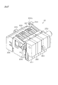
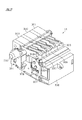
(取込ユニット16の説明)
取込ユニット16は、遊技者による操作に基づき遊技球を所定個数ずつ取り込むための取込手段を構成するものであり、該取込ユニット16による所定個数分の遊技球の取込により毎回の遊技(ゲーム)の開始条件が成立し、遊技開始の準備が整えられるようになっている。
(Description of capture unit 16)
The take-in unit 16 constitutes a take-in means for taking in a predetermined number of game balls based on an operation by the player. Each take-in unit 16 takes in a predetermined number of game balls. The (game) start condition is satisfied, and preparations for starting the game are made.
図29は取込ユニット16を手前側から見た斜視図、図30は同取込ユニット16を後方側から見た斜視図、図31は同取込ユニット16の分解斜視図である。取込ユニット16には3個の取込装置301,302,303が重なるようにして設けられており、取込ユニット16は全体として略立方体形状となっている。以下の説明では、図29において手前側に位置する取込装置301を「第1取込装置」、中央に位置する取込装置302を「第2取込装置」、奥側に位置する取込装置303を「第3取込装置」とも言うこととする。
29 is a perspective view of the capture unit 16 as viewed from the front side, FIG. 30 is a perspective view of the capture unit 16 as viewed from the rear side, and FIG. 31 is an exploded perspective view of the capture unit 16. The take-in unit 16 is provided with three take-in devices 301, 302, and 303 so as to overlap each other, and the take-up unit 16 has a substantially cubic shape as a whole. In the following description, in FIG. 29, the capture device 301 located on the front side is referred to as “first capture device”, the capture device 302 located in the center is referred to as “second capture device”, and the capture device located on the back side. The device 303 is also referred to as a “third capture device”.
各取込装置301〜303の上面には、上方に開放されて外部に露出した状態で入口通路305,306,307が三列に形成されている。これら入口通路305〜307は、取込ユニット16における遊技球入口部を構成するものであり、ドアブロック4としての完成状態では、上皿151から供給される遊技球が先ずは入口通路305〜307に案内され、その後一列に並んだ状態で順次取り込まれる。同完成状態では、上皿151に設けた開口部164(図21参照)を通じて上方から入口通路305〜307が視認可能となっている。各取込装置301〜303の側面にはこれらを結合させるための結合ケース部材308が取り付けられている。結合ケース部材308内には、本取込ユニット16における電気配線等を一括して集め、主制御装置等に対して電気的に接続可能とする取込ユニット中継基板309が収容されている。
On the upper surface of each of the capture devices 301 to 303, inlet passages 305, 306, and 307 are formed in three rows so as to be opened upward and exposed to the outside. These entrance passages 305 to 307 constitute a game ball entrance portion in the take-in unit 16, and in the completed state as the door block 4, the game balls supplied from the upper plate 151 are first entered into the entrance passages 305 to 307. And then sequentially taken in a line. In the completed state, the inlet passages 305 to 307 are visible from above through an opening 164 (see FIG. 21) provided in the upper plate 151. A coupling case member 308 for coupling them is attached to the side surfaces of the respective capture devices 301 to 303. In the coupling case member 308, a take-in unit relay board 309 that collects the electrical wiring and the like in the take-in unit 16 at a time and can be electrically connected to the main control device or the like is accommodated.
(取込装置301〜303の説明)
次に、各取込装置301〜303の構成を説明する。ただし、各取込装置301〜303は、概ね同様の構成をしているため、ここでは基本的に第3取込装置303を例に挙げて説明する。図32は、取込装置303の内部構造を示す断面図、図33は、取込装置303を分解して示す斜視図である。なお、以下の説明では便宜上、図32に示す状態で上下左右の各方向を記載する。
(Description of capture devices 301-303)
Next, the configuration of each of the capture devices 301 to 303 will be described. However, since each of the capture devices 301 to 303 has substantially the same configuration, the third capture device 303 is basically described as an example here. FIG. 32 is a cross-sectional view showing the internal structure of the capture device 303, and FIG. 33 is an exploded perspective view showing the capture device 303. In the following description, for the sake of convenience, the vertical and horizontal directions are described in the state shown in FIG.
取込装置303は、合成樹脂成型品よりなる表裏一対のハウジング部材311,312を備えている。これら両ハウジング311,312がネジ等により結合されることにより略四角箱状の筐体が形成され、その内部空間に、後述する遊技球通路が形成されるとともに該通路を開閉するための開閉ゲート機構などが収容されるようになっている。各ハウジング311,312は、カーボン入りの黒色の樹脂材料により成型されている。以下説明の便宜上、ハウジング部材311を「第1ハウジング」、ハウジング部材312を「第2ハウジング」ともいう。
The take-in device 303 includes a pair of front and back housing members 311 and 312 made of a synthetic resin molded product. These two housings 311 and 312 are connected by screws or the like to form a substantially square box-shaped housing, and a game ball passage to be described later is formed in the internal space, and an opening / closing gate for opening and closing the passage The mechanism is accommodated. Each housing 311, 312 is molded from a black resin material containing carbon. For convenience of explanation, the housing member 311 is also referred to as a “first housing”, and the housing member 312 is also referred to as a “second housing”.
因みに、各ハウジング311,312は透明な樹脂材料で成形されていても良い。各ハウジング311,312を透明化することにより、両ハウジング311,312の結合を外すことなく、取込装置内部の遊技球通路や開閉ゲート機構などの他、通路内に貯留された遊技球を視認することができるようになる。
Incidentally, each housing 311 and 312 may be formed of a transparent resin material. By making each housing 311, 312 transparent, it is possible to visually recognize game balls stored in the passage in addition to the game ball passage and the open / close gate mechanism inside the take-in device, without disconnecting the housings 311, 312. Will be able to.
第1ハウジング311及び第2ハウジング312の上面部には、それぞれ通路壁313,314が形成されており、両ハウジング311,312を結合させることで、相対向する通路壁313,314の間に前記入口通路307が形成される。入口通路307の底面は図32の左側に向けて僅かに下り傾斜している。なお、第2ハウジング312の通路壁314には、取込ユニット16をドアブロック4にビス固定するための上述したボス304が一体形成されている。
Passage walls 313 and 314 are respectively formed on the upper surface portions of the first housing 311 and the second housing 312, and the housings 311 and 312 are coupled to each other so that the passage walls 313 and 314 are opposed to each other. An inlet passage 307 is formed. The bottom surface of the entrance passage 307 is slightly inclined downward toward the left side of FIG. The above-described boss 304 for fixing the take-in unit 16 to the door block 4 is integrally formed on the passage wall 314 of the second housing 312.
取込装置303には、前記入口通路307の下流側において、第1ハウジング311と第2ハウジング312とにより囲まれるようにして取込通路315と排出通路316とが設けられている。これら取込通路315及び排出通路316は、入口通路307と同様に、遊技球を一列で通過させるに足りる通路幅を有する。取込通路315は、入口通路307に連続して設けられ、その途中にて鉛直方向に折れ曲がるようにして形成されている。遊技者により所定の遊技開始操作が行われた際、毎回の遊技の開始条件とされる所定個数の遊技球がこの取込通路315を通じて取り込まれる。また、排出通路316は、取込通路315の折れ曲がり部分(コーナー部分)から当該取込通路315より分岐して設けられている。遊技終了に伴う精算時などにおいては、本取込装置303や上皿151に残留している遊技球がこの排出通路316を通じて遊技者に返還される(すなわち、上皿151等の球抜きが行われる)。
The intake device 303 is provided with an intake passage 315 and a discharge passage 316 so as to be surrounded by the first housing 311 and the second housing 312 on the downstream side of the inlet passage 307. Similar to the entrance passage 307, the intake passage 315 and the discharge passage 316 have passage widths sufficient to allow the game balls to pass in a row. The intake passage 315 is provided continuously to the inlet passage 307 and is formed to bend in the vertical direction in the middle thereof. When a predetermined game start operation is performed by the player, a predetermined number of game balls, which are conditions for starting each game, are taken in through the take-in passage 315. Further, the discharge passage 316 is provided so as to be branched from the bent portion (corner portion) of the intake passage 315 from the intake passage 315. At the time of payment at the end of the game, the game balls remaining on the take-in device 303 and the upper plate 151 are returned to the player through the discharge passage 316 (ie, the upper plate 151 and the like are removed). )
なお、第1ハウジング311と第2ハウジング312は、厚さ方向の寸法が異なるものとなっており、入口通路307、取込通路315及び排出通路316は、大部分が第1ハウジング311側に形成されるようになっている。これにより、遊技球が実際に接触する経路は、両ハウジング311,312の境界部分(接合部分)から外れた部位となり、境界部分に溜まったゴミやほこり等により遊技球の流れが阻害されるといった不都合が回避されるようになっている。
The first housing 311 and the second housing 312 have different thickness dimensions, and most of the inlet passage 307, the intake passage 315, and the discharge passage 316 are formed on the first housing 311 side. It has come to be. As a result, the path where the game balls actually come into contact with each other is a part deviated from the boundary part (joint part) between the housings 311 and 312, and the flow of the game ball is obstructed by dust, dust, etc. accumulated in the boundary part. Inconvenience is to be avoided.
また、第1,第2ハウジング311,312には、入口通路307及び取込通路315に沿って一筋の突条部317が設けられている。この突条部317は、入口通路307及び取込通路315を通過する遊技球の外周面に接触するようにして通路の中央部(入口通路307にあっては上下幅方向の中央部、取込通路315にあっては左右幅方向の中央部)に設けられている。突条部317の高さ(通路内部への突出寸法)は0.5mm程度であり、これにより入口通路307及び取込通路315の通路幅が狭められるようになっている。つまり、入口通路307及び取込通路315は基本的に通路幅が12mm程度であるが、突条部317を設けることにより、実質的な通路幅が11.5mm程度に狭められている。これにより、入口通路307及び取込通路315の内壁と遊技球との隙間間隔(遊び)を減らすことができ、安定した状態で遊技球が流下することとなる。特に、取込通路315においては、後述する遊技球検出が行われるため、その検出ミスを低減させることができる。ただし、突条部317は、第1,第2ハウジング311,312のいずれか一方にのみ設けられる構成であっても良い。前記整流部における突条部317の設置は任意である。
The first and second housings 311 and 312 are provided with a straight protrusion 317 along the inlet passage 307 and the intake passage 315. The protruding portion 317 is in contact with the outer peripheral surface of the game ball passing through the inlet passage 307 and the intake passage 315 (in the inlet passage 307, the central portion in the vertical width direction, the intake portion). In the passage 315, it is provided in the central portion in the left-right width direction. The height of the protrusion 317 (projecting dimension into the passage) is about 0.5 mm, so that the passage widths of the inlet passage 307 and the intake passage 315 are narrowed. That is, the entrance passage 307 and the intake passage 315 basically have a passage width of about 12 mm, but the provision of the protrusion 317 narrows the substantial passage width to about 11.5 mm. Thereby, the clearance gap (play) between the inner wall of the entrance passage 307 and the intake passage 315 and the game ball can be reduced, and the game ball flows down in a stable state. In particular, in the take-in passage 315, game ball detection, which will be described later, is performed, so that detection errors can be reduced. However, the protrusion 317 may be configured to be provided only in one of the first and second housings 311 and 312. Installation of the protrusion 317 in the rectifying unit is arbitrary.
ハウジング内部空間において取込通路315の側方には、当該取込通路315の鉛直方向部分に沿うようにして取込ゲート部材320が設けられている。取込ゲート部材320は、支軸321により回動可能に支持されており、その支軸321を支点とする回動により、該取込ゲート部材320の先端部に設けた爪部320aが取込通路315に対して出没する。このとき、取込通路315の通路壁には通路切欠部322が形成されており、その通路切欠部322を介して取込ゲート部材320の爪部320aが出没する。取込通路315に対して取込ゲート部材320の爪部320aが突出した状態である場合、取込通路315を介しての遊技球の通過が阻止される。また、取込通路315に対して取込ゲート部材320の爪部320aが没入した状態である場合、取込通路315を介しての遊技球の通過が許容される。
A take-in gate member 320 is provided on the side of the take-in passage 315 in the housing internal space so as to follow the vertical direction portion of the take-in passage 315. The take-in gate member 320 is rotatably supported by a support shaft 321, and the claw portion 320 a provided at the distal end portion of the take-in gate member 320 is taken in by turning about the support shaft 321. Invade with respect to passage 315. At this time, a passage notch 322 is formed in the passage wall of the take-in passage 315, and the claw portion 320 a of the take-in gate member 320 goes in and out through the passage notch 322. When the claw portion 320a of the take-in gate member 320 protrudes from the take-in passage 315, the game ball is prevented from passing through the take-in passage 315. Further, when the claw portion 320a of the take-in gate member 320 is immersed in the take-in passage 315, the game ball is allowed to pass through the take-in passage 315.
かかる場合、取込ゲート部材320の爪部320aの出没位置が取込通路315におけるコーナー部分の直ぐ下流位置であるため、換言すれば通路切欠部322が取込通路315におけるコーナー部分の直ぐ下流位置に形成されているため、取込ゲート部材320の爪部320aが通路内に突出した状態(通過阻止状態)において、取込通路315のコーナー部まで流れてきた遊技球が該取込通路315の鉛直部分に流れ込むことがない構成となっている。
In such a case, since the protruding and retracting position of the claw portion 320a of the intake gate member 320 is a position immediately downstream of the corner portion in the intake passage 315, in other words, the passage notch portion 322 is immediately downstream of the corner portion in the intake passage 315. Therefore, in the state where the claw portion 320a of the intake gate member 320 protrudes into the passage (passage prevention state), the game ball flowing to the corner portion of the intake passage 315 is in the intake passage 315. It has a configuration that does not flow into the vertical part.
ハウジング内部空間には、取込ゲート部材320の駆動源としてソレノイド325が配設されている。ソレノイド325は、通電により伸縮方向に移動する出力軸325aを有しており、当該ソレノイド325は、取込ゲート部材320の右方において出力軸325aが下方へと突き出るように配設されている。また、ソレノイド325の出力軸325aには、当該出力軸325aを伸長状態で保持するためのコイルバネ326が設けられている。ソレノイド325は、ソレノイドカバー327によって第1ハウジング311に固定されている。
A solenoid 325 is disposed in the housing internal space as a drive source for the take-in gate member 320. The solenoid 325 has an output shaft 325a that moves in the expansion / contraction direction when energized. The solenoid 325 is disposed so that the output shaft 325a protrudes downward on the right side of the take-in gate member 320. The output shaft 325a of the solenoid 325 is provided with a coil spring 326 for holding the output shaft 325a in an extended state. The solenoid 325 is fixed to the first housing 311 by a solenoid cover 327.
ソレノイド出力軸325aの先端部にはガイド331が取り付けられている。ガイド331には回動片332の一部が係合されており、同回動片332の他部が取込ゲート部材320の後端部に駆動連結されている。符号333は、回動片332のほぼ中央部に設けられ該回動片332を回動可能に支持する支軸である。
A guide 331 is attached to the tip of the solenoid output shaft 325a. A part of the rotating piece 332 is engaged with the guide 331, and the other part of the rotating piece 332 is drivingly connected to the rear end portion of the take-in gate member 320. Reference numeral 333 is a support shaft that is provided substantially at the center of the rotating piece 332 and rotatably supports the rotating piece 332.
本構成によれば、ソレノイド325への通電がない場合には、図示の如くコイルバネ326の付勢力によって出力軸325aが伸長した状態で保持され、取込ゲート部材320の爪部320aが取込通路315内に突出した状態とされる。これにより、取込通路315が閉鎖される。一方、ソレノイド325が通電されると、コイルバネ326の付勢力に抗して出力軸325aが縮み方向に移動する。よって、ガイド331及び回動片332を介して取込ゲート部材320が回動し(図32では時計回り方向に回動し)、取込ゲート部材320の爪部320aが取込通路315外に引っ込んだ状態とされる。これにより、取込通路315が開放される。また、ソレノイド325への通電を中止すると、コイルバネ326の付勢力によって出力軸325aが伸長状態となり、取込ゲート部材320の爪部320aが取込通路315内に突出した状態に戻る。
According to this configuration, when the solenoid 325 is not energized, the output shaft 325a is held in an extended state by the urging force of the coil spring 326 as shown, and the claw portion 320a of the take-in gate member 320 is taken in the take-in passage. It is in a state of protruding into 315. Thereby, the intake passage 315 is closed. On the other hand, when the solenoid 325 is energized, the output shaft 325a moves in the contracting direction against the urging force of the coil spring 326. Accordingly, the take-in gate member 320 is turned through the guide 331 and the turning piece 332 (turned in the clockwise direction in FIG. 32), and the claw portion 320a of the take-in gate member 320 is outside the take-in passage 315. Retracted. Thereby, the intake passage 315 is opened. When the energization of the solenoid 325 is stopped, the output shaft 325 a is extended by the urging force of the coil spring 326, and the claw portion 320 a of the take-in gate member 320 returns to the state in which it protrudes into the take-in passage 315.
一方、第1,第2ハウジング311,312において排出通路316の入口位置には、それぞれ貫通孔337,338が設けられており、その貫通孔337,338を前後方向に貫通するようにして排出ゲート部材340が設けられている。排出ゲート部材340は、取込装置301〜303に個別に設けられるのではなく、全取込装置301〜303に共通に設けられるものとなっており、該排出ゲート部材340の作動状態によって、各取込装置301〜303において同時に遊技球の排出(球抜き)が許容又は阻止されるようになっている。
On the other hand, through holes 337 and 338 are respectively provided at the inlet positions of the discharge passage 316 in the first and second housings 311 and 312, and the discharge gates pass through the through holes 337 and 338 in the front-rear direction. A member 340 is provided. The discharge gate member 340 is not provided individually to the capture devices 301 to 303 but is provided in common to all the capture devices 301 to 303. Depending on the operating state of the discharge gate member 340, each In the take-in devices 301 to 303, the discharge (ball removal) of the game balls is allowed or prevented at the same time.
ここで、排出ゲート部材340の詳細を図34に基づいて説明する。排出ゲート部材340は、全体として略長方形状をなしており、3カ所に略正方形状の開口部341,342,343が形成されている。これら開口部341〜343は各取込装置301〜303に設けられた排出通路316にそれぞれ対応するものであり、一定間隔を隔ててそれぞれ設けられている。なお、開口部341〜343は排出通路316の一部を構成する。この場合、排出ゲート部材340がその長手方向(取込ユニット153の前後方向)に移動することにより、排出通路316が閉鎖又は開放の状態とされる。すなわち、排出ゲート部材340が初期位置にある場合、排出ゲート部材340の壁板部により各取込装置301〜303の排出通路316が閉鎖され、当該通路316を通じての遊技球の排出が阻止される。また、排出ゲート部材340がその長手方向に移動すると、排出ゲート部材340の開口部341〜343により各取込装置301〜303の排出通路316が一斉に開放され、当該通路316を通じての遊技球の排出が許容される。
Here, details of the discharge gate member 340 will be described with reference to FIG. The discharge gate member 340 has a substantially rectangular shape as a whole, and substantially square openings 341, 342, 343 are formed at three locations. These openings 341 to 343 respectively correspond to the discharge passages 316 provided in the respective intake devices 301 to 303, and are provided at regular intervals. The openings 341 to 343 constitute a part of the discharge passage 316. In this case, when the discharge gate member 340 moves in the longitudinal direction (the front-rear direction of the take-in unit 153), the discharge passage 316 is closed or opened. That is, when the discharge gate member 340 is in the initial position, the discharge passage 316 of each of the capture devices 301 to 303 is closed by the wall plate portion of the discharge gate member 340, and the discharge of the game ball through the passage 316 is prevented. . Further, when the discharge gate member 340 moves in the longitudinal direction, the discharge passages 316 of the intake devices 301 to 303 are simultaneously opened by the openings 341 to 343 of the discharge gate member 340, and the game balls passing through the passages 316 are opened. Discharge is allowed.
開口部341〜343の下方には、それぞれ球案内突部344,345,346が形成されている。この球案内突部344〜346の上面は、各開口部341〜343の底部上面に連続して同一角度で設けられており、その角度は排出通路316の入口部の傾斜角度に合致している。これにより、遊技球が開口部341〜343を介して排出通路316に流入する際には、球案内突部344〜346上を転がりながら遊技球が通過し、排出通路316への遊技球の流入がスムーズに行われることとなる。
Ball guide protrusions 344, 345, and 346 are formed below the openings 341 to 343, respectively. The upper surfaces of the ball guide protrusions 344 to 346 are continuously provided at the same angle as the upper surfaces of the bottoms of the openings 341 to 343, and the angle matches the inclination angle of the inlet portion of the discharge passage 316. . Accordingly, when the game ball flows into the discharge passage 316 through the openings 341 to 343, the game ball passes while rolling on the ball guide protrusions 344 to 346, and the game ball flows into the discharge passage 316. Will be performed smoothly.
排出ゲート部材340の一方の端部にはバネ受け部347が形成され、他方の端部にはロッド部348が形成されている。かかる場合、図31等に示すように、第3取込装置303の外側にカバー部材351が設けられ、そのカバー部材351と排出ゲート部材340のバネ受け部347との間にコイルバネ352が組み込まれる。なお、符号353はコイルバネ352を収容するためのバネ収容部である。
A spring receiving portion 347 is formed at one end of the discharge gate member 340, and a rod portion 348 is formed at the other end. In this case, as shown in FIG. 31 and the like, a cover member 351 is provided outside the third take-in device 303, and a coil spring 352 is incorporated between the cover member 351 and the spring receiving portion 347 of the discharge gate member 340. . Reference numeral 353 denotes a spring accommodating portion for accommodating the coil spring 352.
排出ゲート部材340は、コイルバネ352の付勢力によって一方向に常に付勢される。このとき、排出ゲート部材340は、コイルバネ352の付勢力により初期位置(排出通路316を閉鎖する位置)に保持され、ロッド部348から力が加わると、コイルバネ352の付勢力に抗して排出通路316の開放位置に移行する。
The discharge gate member 340 is always urged in one direction by the urging force of the coil spring 352. At this time, the discharge gate member 340 is held at the initial position (position where the discharge passage 316 is closed) by the biasing force of the coil spring 352, and when a force is applied from the rod portion 348, the discharge gate member 340 resists the biasing force of the coil spring 352. 316 shifts to the open position.
図29等に示すように、取込ユニット16において第1取込装置301側にはロッド部348が突出しており、このロッド部348が、前述した排出操作伝達装置154により押し込み操作されるようになっている。また、図34等に示すように、排出ゲート部材340の一方の端部において、前記バネ受け部347の下方には、排出ゲート部材340の長手方向に延びる突起部355が形成されている。一方、排出ゲート部材340の一端側に設けられるカバー部材351には排出ゲート検出センサ356が設けられている。かかる構成において、排出操作伝達装置154の操作に伴い排出ゲート部材340が動作すると、その動作状態が排出ゲート検出センサ356により逐次検出されるようになっている。その詳細を図35により説明する。図35において、(a)はロッド部348(排出ゲート部材340)を押し込み操作する前の初期状態を示し、(b)はロッド部348(排出ゲート部材340)を押し込み操作した状態を示す。
As shown in FIG. 29 and the like, the rod unit 348 protrudes on the first capture device 301 side in the capture unit 16 so that the rod portion 348 is pushed by the discharge operation transmission device 154 described above. It has become. As shown in FIG. 34 and the like, a protruding portion 355 extending in the longitudinal direction of the discharge gate member 340 is formed below the spring receiving portion 347 at one end portion of the discharge gate member 340. On the other hand, a discharge gate detection sensor 356 is provided on the cover member 351 provided on one end side of the discharge gate member 340. In this configuration, when the discharge gate member 340 is operated in accordance with the operation of the discharge operation transmission device 154, the operation state is sequentially detected by the discharge gate detection sensor 356. Details thereof will be described with reference to FIG. 35A shows an initial state before the rod portion 348 (discharge gate member 340) is pushed in, and FIG. 35B shows a state where the rod portion 348 (discharge gate member 340) is pushed.
図35に示すように、取込ユニット16の側方(本遊技機1では前側)に排出操作伝達装置154が設けられており、ロッド部348の先端部が排出操作伝達装置154の第2リンク片195の回動先端部に相対向している。この場合、図35の(a)では、排出ゲート部材340が初期位置にあるため、排出通路316の入口が閉鎖されており、遊技球の排出通路316への流れ込みが阻止されている。この状態では、排出ゲート部材340の突起部355が取込装置303の外方に突出しておらず、該突起部355が排出ゲート検出センサ356により検出されない。
As shown in FIG. 35, a discharge operation transmission device 154 is provided on the side of the take-in unit 16 (the front side in this gaming machine 1), and the tip of the rod portion 348 is the second link of the discharge operation transmission device 154. Opposite the rotating tip of the piece 195. In this case, in FIG. 35A, since the discharge gate member 340 is in the initial position, the inlet of the discharge passage 316 is closed and the flow of the game ball into the discharge passage 316 is prevented. In this state, the protrusion 355 of the discharge gate member 340 does not protrude outward from the capture device 303, and the protrusion 355 is not detected by the discharge gate detection sensor 356.
これに対し、図35の(b)では、排出操作伝達装置154において操作レバー198の操作により各リンク片194,195が回動動作し、その動作がロッド部348に伝達される。これにより、排出ゲート部材340が排出通路316を開放する位置に移動し、遊技球の排出通路316への流れ込みが許容される。この状態では、排出ゲート部材340の突起部355が取込装置303の外方に突出し、それに伴い該突起部355が排出ゲート検出センサ356により検出される。排出ゲート検出センサ356は、排出ゲート部材340の操作状態(操作位置)を検出するための排出操作検出手段を構成するものとなっている。
On the other hand, in FIG. 35B, the link pieces 194 and 195 are rotated by the operation of the operation lever 198 in the discharge operation transmission device 154, and the operation is transmitted to the rod portion 348. Thereby, the discharge gate member 340 moves to a position where the discharge passage 316 is opened, and the flow of the game ball into the discharge passage 316 is allowed. In this state, the protruding portion 355 of the discharge gate member 340 protrudes outward from the capture device 303, and accordingly, the protruding portion 355 is detected by the discharge gate detection sensor 356. The discharge gate detection sensor 356 constitutes a discharge operation detection means for detecting the operation state (operation position) of the discharge gate member 340.
排出ゲート検出センサ356による検出信号は、後述する主制御装置505に対して出力される。この場合、主制御装置505は、排出ゲート検出センサ356の検出信号に基づいて排出通路316の開閉の状態を検知し、排出通路316が開放状態にある場合には遊技球の取込動作(取込ゲート部材320の動作)を禁止するなどの処理を実行する。排出通路316の開放時に遊技球の取込動作を禁止することにより、遊技球の取込状態が不安定になったり、取り込まれる遊技球の検知精度が低下したりするなどの不都合が解消される。
A detection signal from the discharge gate detection sensor 356 is output to a main controller 505 described later. In this case, the main controller 505 detects the open / close state of the discharge passage 316 based on the detection signal of the discharge gate detection sensor 356, and when the discharge passage 316 is in the open state, the game ball take-in operation (take-in) Processing such as prohibiting the operation of the insertion gate member 320 is performed. By prohibiting the taking-in operation of the game ball when the discharge passage 316 is opened, inconveniences such as an unstable take-in state of the game ball and a decrease in detection accuracy of the taken game ball are eliminated. .
また、図32,図33に示すように、取込装置303には、取込通路315における遊技球の通過を検出するセンサユニット370が設けられている。このセンサユニット370は、取込通路315を通過する遊技球数をカウントするための遊技球カウント手段を構成するものであり、発光素子と受光素子とからなる周知の光学式センサを備える。
As shown in FIGS. 32 and 33, the take-in device 303 is provided with a sensor unit 370 that detects the passage of a game ball in the take-in passage 315. This sensor unit 370 constitutes a game ball counting means for counting the number of game balls passing through the take-in passage 315, and includes a known optical sensor composed of a light emitting element and a light receiving element.
センサユニット370は、略コ字形状をなしており、第1,第2ハウジング311,312に跨るようにして組み付けられている。詳細には、センサユニット370は、取込装置303の厚さ方向に延びるセンサ本体部371と、該センサ本体部371の両端から各ハウジング311,312の外壁面に沿って取込通路315側に延びるアーム部372,373とを有している。センサ本体部371にはセンサ回路基板(図示略)が収容されており、そのセンサ本体部371の背面部にはセンサ回路基板上に設けたコネクタ端子374を外部に露出させるためのコネクタ穴371aが形成されている。
The sensor unit 370 has a substantially U-shape and is assembled so as to straddle the first and second housings 311 and 312. Specifically, the sensor unit 370 includes a sensor body 371 extending in the thickness direction of the take-in device 303, and both ends of the sensor body 371 along the outer wall surfaces of the housings 311 and 312 toward the take-in passage 315. And extending arm portions 372 and 373. A sensor circuit board (not shown) is accommodated in the sensor body 371, and a connector hole 371a for exposing a connector terminal 374 provided on the sensor circuit board to the outside is provided on the back surface of the sensor body 371. Is formed.
アーム部372,373のうち一方には発光素子が収容されるとともに、他方には受光素子が収容されている。また、アーム部372,373の先端部には、互いに内側となる部位に上下一対のセンサ検出孔376が形成されている。この場合、アーム部372,373内には各2個ずつの発光素子と受光素子が収容されており、これら各素子はセンサ検出孔376を通じて発光及び受光を行うようになっている。第1,第2ハウジング311,312には、上下一対の透孔378が形成されており、ハウジング接合状態で、各ハウジング311,312にセンサユニット370が組み付けられた場合には、各アーム部372,373の先端部に設けたセンサ検出孔376の位置と、各ハウジング311,312の透孔378の位置とが合致し、それらが向き合うようにして配置される。
A light emitting element is accommodated in one of the arm portions 372 and 373, and a light receiving element is accommodated in the other. In addition, a pair of upper and lower sensor detection holes 376 are formed at the distal ends of the arm portions 372 and 373 at portions that are inside each other. In this case, two light emitting elements and two light receiving elements are accommodated in the arm portions 372 and 373, respectively, and each of these elements emits and receives light through the sensor detection hole 376. A pair of upper and lower through holes 378 are formed in the first and second housings 311 and 312. When the sensor unit 370 is assembled to each housing 311 and 312 in the housing joined state, each arm portion 372. , 373 are arranged such that the position of the sensor detection hole 376 provided at the front end portion of the housing 311 matches the position of the through hole 378 of each housing 311, 312.
図32に示すように、ハウジング内部において、透孔378は取込通路315内で中心から幾分オフセットした位置に設けられている。この透孔378の位置がセンサユニット370による遊技球検出位置である。この場合特に、透孔378は、取込ゲート部材320の先端部に形成した爪部320aの真下位置(図32において取込通路315の右方オフセット位置)に設けられており、取込ゲート部材320の爪部320aが没入側に移動しない限りセンサユニット370により遊技球が検出されることはないようになっている。仮に、透孔378が取込通路315において逆側(図32において取込通路315の左方オフセット位置)に設けられた場合を想定すると、取込ゲート部材320の爪部320aが突出位置にある状態での遊技球誤検出(排出通路316を通じての遊技球排出時の遊技球誤検出も含む)を防止するには透孔378の位置を図示の位置よりも下方に下げる必要が生じるが、本遊技機1の上記構成によれば、透孔378を取込ゲート部材320の爪部320aの近傍に配置することが可能となる。したがって、取込ゲート部材320の開放により流下する遊技球をいち早く検出することが可能となる。
As shown in FIG. 32, the through hole 378 is provided in the intake passage 315 at a position slightly offset from the center inside the housing. The position of the through hole 378 is a game ball detection position by the sensor unit 370. In this case, in particular, the through hole 378 is provided at a position directly below the claw portion 320a formed at the distal end portion of the intake gate member 320 (a right offset position of the intake passage 315 in FIG. 32). A game ball is not detected by the sensor unit 370 unless the claw portion 320a of 320 moves to the immersive side. If it is assumed that the through hole 378 is provided on the opposite side of the intake passage 315 (the left offset position of the intake passage 315 in FIG. 32), the claw portion 320a of the intake gate member 320 is in the protruding position. In order to prevent erroneous detection of the game ball in the state (including erroneous detection of the game ball when discharging the game ball through the discharge passage 316), it is necessary to lower the position of the through hole 378 below the illustrated position. According to the above configuration of the gaming machine 1, the through hole 378 can be disposed in the vicinity of the claw portion 320 a of the take-in gate member 320. Therefore, it is possible to quickly detect a game ball that flows down due to the opening of the intake gate member 320.
取込ゲート部材320が開放された状態で遊技球が取り込まれる際、センサユニット370において上下の各センサ素子(発光素子+受光素子)では、先に上流側のセンサ素子で遊技球が検出され、その後下流側のセンサ素子で遊技球が検出される。これら各センサ素子による検出信号は、遊技球の取込を管理する後述の主制御装置505に順に出力される。この場合、主制御装置505では、各センサ素子による遊技球検出信号によって正常に遊技球の取込が行われたかどうかが判定される。具体的には、所定の規定時間内に、上流側のセンサ素子→下流側のセンサ素子の順で遊技球の検出が行われた場合のみ、正常に遊技球の取込が行われたと判定される。
When a game ball is taken in with the take-in gate member 320 opened, in the upper and lower sensor elements (light emitting element + light receiving element) in the sensor unit 370, the game ball is first detected by the upstream sensor element, Thereafter, the game ball is detected by the sensor element on the downstream side. Detection signals from these sensor elements are sequentially output to a main controller 505 described later that manages the taking-in of game balls. In this case, main controller 505 determines whether or not a game ball has been normally taken in based on a game ball detection signal from each sensor element. Specifically, it is determined that the game ball has been normally taken in only when the game ball is detected in the order of the upstream sensor element → the downstream sensor element within a predetermined specified time. The
仮に、上流側のセンサ素子による遊技球検出から下流側のセンサ素子による遊技球検出までの所要時間が規定時間よりも長い場合や、正常時とは逆に下流側のセンサ素子→上流側のセンサ素子の順で遊技球の検出が行われた場合には異常とみなされ、その旨が報知されるとともにそれ以降の遊技が停止される。したがって、例えば、遊技球やその他ダミー被検出物にひも等を付けて上下させることにより、あたかも複数の遊技球が取り込まれたようにするなどの不正行為が防止できるようになっている。
If the required time from the detection of the game ball by the upstream sensor element to the detection of the game ball by the downstream sensor element is longer than the specified time, or contrary to normal, the downstream sensor element → the upstream sensor When the game balls are detected in the order of the elements, it is regarded as abnormal, the fact is notified, and the subsequent games are stopped. Therefore, for example, by attaching a string or the like to a game ball or other dummy object to be moved up and down, it is possible to prevent cheating as if a plurality of game balls were taken in.
上記のように、センサユニット370では各アーム部372,373のうち一方が発光部、他方が受光部となっており、それら発光部と受光部とが一体で設けられている。これにより、発光素子と受光素子との位置合わせ精度を高めることができ、遊技球の検出精度を良好なものとすることができる。また、各アーム部372,373を連結するセンサ本体部371にセンサ回路基板を設けるとともに、該センサ回路基板上に設けたコネクタ端子374によって外部基板との電気的な接続を可能としたため、発光素子や受光素子に繋がる信号線を統合してまとめることができ、さらに外部基板に対する配線の接続も容易なものとなる。
As described above, in the sensor unit 370, one of the arm portions 372 and 373 is a light emitting portion and the other is a light receiving portion, and the light emitting portion and the light receiving portion are provided integrally. Thereby, the alignment precision of a light emitting element and a light receiving element can be raised, and the detection precision of a game ball can be made favorable. In addition, a sensor circuit board is provided in the sensor main body 371 that connects the arm parts 372 and 373, and the connector terminal 374 provided on the sensor circuit board enables electrical connection to an external board. In addition, the signal lines connected to the light receiving element can be integrated and integrated, and the wiring can be easily connected to the external substrate.
また、取込通路315の最下流部には、取込ゲート部材320を通過した遊技球をセンサユニット370で検出した後、同遊技球を再度検出するための下流側取込センサ380が設けられている。この下流側取込センサ380は磁気検出タイプの近接センサにて構成されており、遊技球の通過に伴う磁界の変化により遊技球の通過を検出する。すなわち、板状のセンサ本体部381には貫通孔381aが設けられており、センサ本体部381では貫通孔381aを遊技球が通過する際の磁界の変化が検出されて電気信号として出力される。貫通孔381aは略真円状をなしており、その直径は取込通路315の幅寸法に概ね一致している。センサ本体部381にはコネクタ端子382が設けられている。
Further, a downstream side intake sensor 380 is provided at the most downstream portion of the intake passage 315 for detecting the game ball that has passed through the intake gate member 320 by the sensor unit 370 and then detecting the game ball again. ing. This downstream side intake sensor 380 is configured by a magnetic detection type proximity sensor, and detects the passage of the game ball by the change of the magnetic field accompanying the passage of the game ball. That is, the plate-shaped sensor main body 381 is provided with a through hole 381a, and the sensor main body 381 detects a change in magnetic field when a game ball passes through the through hole 381a and outputs it as an electrical signal. The through hole 381 a has a substantially perfect circle shape, and its diameter substantially matches the width dimension of the intake passage 315. A connector terminal 382 is provided on the sensor main body 381.
下流側取込センサ380による検出信号は、前記センサユニット370の検出信号と同様、後述する主制御装置505に対して出力される。この場合、主制御装置505では、前記センサユニット370の検出信号と下流側取込センサ380の検出信号とに基づいて今回の遊技球取込の検出結果(センサユニット370による取込判定の結果)が正規なものかどうか、すなわち不正なものでないかどうかが判定される。具体的には、センサユニット370による球技球カウント数(例えば、一方のセンサ素子の検出結果による遊技球カウント数)と、下流側取込センサ380による遊技球カウント数とを比較し、それら各カウント数が一致する場合に、今回の遊技球取込の検出結果(センサユニット370による取込判定の結果)が正規であると判定する。これに対し、各カウント数が不一致となる場合に、今回の遊技球取込の検出結果(センサユニット370による取込判定の結果)が正規なものでなく、不正行為によるものであると判定する。
Similar to the detection signal of the sensor unit 370, the detection signal from the downstream intake sensor 380 is output to the main controller 505 described later. In this case, the main controller 505 detects the current game ball uptake detection result (result of uptake determination by the sensor unit 370) based on the detection signal of the sensor unit 370 and the detection signal of the downstream uptake sensor 380. Is determined to be legitimate, i.e., not fraudulent. Specifically, the ball game ball count number by the sensor unit 370 (for example, the game ball count number by the detection result of one sensor element) is compared with the game ball count number by the downstream side intake sensor 380, and each count When the numbers match, it is determined that the detection result of the current game ball uptake (result of the uptake determination by the sensor unit 370) is normal. On the other hand, when the count numbers do not match, it is determined that the detection result of the current game ball capture (the result of the capture determination by the sensor unit 370) is not a regular one but is due to an illegal act. .
取込ユニット16に対する不正行為として、センサユニット370に、遊技球の通過を誤検出させるように発光動作する不正装置を取り付けることが考えられる。例えば、実際の遊技球取込に関係なく点滅動作するような2つの発光体を備えてなる不正装置を本取込ユニット16に取り付け、それら各発光体を所定順序で点滅させることで遊技球の通過を誤検出させるようにする。かかる不正行為がなされた場合、センサユニット370による遊技球検出だけでは不正行為による遊技球の誤検出を回避することが困難であった。この点、上記のように下流側取込センサ380の検出信号による不正確認によって、不正行為による遊技球の誤検出を回避することができる。
As a fraudulent act with respect to the take-in unit 16, it is conceivable to attach a fraudulent device that emits light so as to cause the sensor unit 370 to erroneously detect the passage of a game ball. For example, a fraudulent device comprising two light emitters that blinks regardless of actual game ball take-in is attached to the take-in unit 16, and these light emitters are blinked in a predetermined order to play game balls. Make sure that the passage is falsely detected. When such an illegal act is performed, it is difficult to avoid erroneous detection of the game ball due to the illegal act only by the detection of the game ball by the sensor unit 370. In this regard, it is possible to avoid erroneous detection of a game ball due to fraudulent action by fraud confirmation based on the detection signal of the downstream intake sensor 380 as described above.
取込通路315に、互いに検出方式の異なる2つのセンサ装置(センサユニット370、下流側取込センサ380)を設けたため、各センサ装置のいずれにおいても遊技球を誤検出させるようにすることは困難なものとなる。故に、取込ユニット16における不正対策が望ましいものとなっている。
Since two sensor devices (sensor unit 370 and downstream side intake sensor 380) having different detection methods are provided in the intake passage 315, it is difficult to erroneously detect a game ball in any of the sensor devices. It will be something. Therefore, countermeasures against fraud in the capture unit 16 are desirable.
上述した取込装置303の各構成部材(排出ゲート部材340を除く、取込ゲート部材320、ソレノイド325を含むゲート駆動機構、センサユニット370等)は、入口通路307と取込通路315とのコーナー部分の内側領域に集約して配設されている。これにより、各構成部材を限られた領域内で効率良く配置することができ、結果として取込装置303の小型化(薄型化も含む)が実現できるようになっている。
Each component of the intake device 303 described above (excluding the discharge gate member 340, the intake gate member 320, the gate drive mechanism including the solenoid 325, the sensor unit 370, etc.) is a corner between the inlet passage 307 and the intake passage 315. It is arranged in a concentrated manner in the inner region of the part. Thereby, each structural member can be efficiently arrange | positioned in the limited area | region, As a result, size reduction (including thickness reduction) of the capture device 303 can be implement | achieved.
上記構成の取込装置301〜303が3連で設けられた本取込ユニット16では、上皿151の案内通路171〜173から各取込装置301〜303にそれぞれ遊技球が供給され、遊技機前面のベットスイッチ37の操作に伴い各取込装置301〜303では各々で遊技球が取り込まれる。具体的には、例えば15個(マックスベット分)の遊技球が取り込まれる場合、全ての取込装置301〜303において同時に取込ゲート部材320が開放位置に操作され、遊技球の取込が一斉に開始される。このとき、各取込装置301〜303では遊技球が5個ずつ取り込まれる。
In the main take-in unit 16 in which the take-in devices 301 to 303 having the above-described configuration are provided in triplicate, game balls are supplied from the guide passages 171 to 173 of the upper plate 151 to the take-in devices 301 to 303, respectively. In accordance with the operation of the front bet switch 37, the respective take-in devices 301 to 303 take in the game balls. Specifically, for example, when 15 (maximum bet) game balls are taken in, the take-in gate member 320 is simultaneously operated to the open position in all the take-in devices 301 to 303, and the take-in of game balls is performed all at once. To begin. At this time, each of the take-in devices 301 to 303 takes in five game balls.
ただし、3個の取込装置301〜303のうちいずれかの取込装置に遊技球が充填されていない場合、又はソレノイド325の故障などでいずれかの取込装置が正常に作動しない場合には、正常な取込動作を行うことができる残りの取込装置により遊技球の取込が行われる。例えば、第1取込装置301に遊技球が充填されていないとき又は同取込装置301のソレノイド325などが故障しているときには、第1取込装置301以外の取込装置(第2,第3取込装置302,303)によって15個の遊技球が取り込まれることとなる。
However, if any of the three capture devices 301 to 303 is not filled with a game ball, or if any of the capture devices does not operate normally due to a malfunction of the solenoid 325, etc. The game balls are taken in by the remaining take-in devices that can perform normal take-in operations. For example, when the first take-in device 301 is not filled with a game ball or when the solenoid 325 of the take-in device 301 is out of order, the take-in devices other than the first take-in device 301 (second, second, 15 game balls are taken in by the 3 take-in devices 302 and 303).
一方、取込装置301〜303や上皿151に残っている遊技球を下皿71へ排出する場合には、遊技機前面の操作レバー198の操作に伴い排出ゲート部材340が操作されて各取込装置301〜303で一斉に遊技球の排出が行われる。
On the other hand, when the game balls remaining on the take-in devices 301 to 303 and the upper plate 151 are discharged to the lower plate 71, the discharge gate member 340 is operated in accordance with the operation of the operation lever 198 on the front side of the gaming machine, and each take-off is performed. The game balls are discharged all at once by the insertion devices 301 to 303.
(面替えブロック5の説明)
次に、面替えブロック5について説明する。図36は面替えブロック5を斜め前方より見た斜視図、図37は同面替えブロック5を斜め後方から見た斜視図、図38は同面替えブロック5の正面図である。また、図39,図40は面替えブロック5の分解斜視図である。
(Explanation of the replacement block 5)
Next, the surface changing block 5 will be described. FIG. 36 is a perspective view of the surface changing block 5 as seen from the oblique front, FIG. 37 is a perspective view of the surface changing block 5 as seen from the oblique rear, and FIG. 38 is a front view of the surface changing block 5. 39 and 40 are exploded perspective views of the surface changing block 5. FIG.
面替えブロック5は主要な構成として、合成樹脂製の前面枠501と、図柄表示装置としてのリール装置503と、補助演出装置としての液晶表示装置504と、遊技に関わる主たる各種制御を実施する主制御装置505と、主制御装置505からの指令に基づく従たる表示制御等を実施する表示制御装置506と、主制御装置505を装着するための主制御装置用台座ベース507と、表示制御装置506を装着するための表示制御装置用台座ベース508とを備えている。本実施の形態では、面替えブロック5は、本遊技機1の遊技内容を決定する主要部品を全て備える構成となっており、仮に遊技ホール等において機種入替を行う場合には、この面替えブロック5を現機種のものから新たな機種のものに入れ替えることで機種入替を行うことができるようになっている。すなわち、面替えブロック5は機種入替時などにおける交換ユニットとなっている。
The main part of the surface changing block 5 is a synthetic resin front frame 501, a reel device 503 as a symbol display device, a liquid crystal display device 504 as an auxiliary effect device, and a main control unit that performs various main controls relating to the game. A control device 505, a display control device 506 for performing subordinate display control based on a command from the main control device 505, a pedestal base 507 for the main control device for mounting the main control device 505, and a display control device 506 And a display control device base base 508. In the present embodiment, the face change block 5 is configured to include all the main parts that determine the game content of the gaming machine 1, and this face change block is used when changing the model in a game hall or the like. The model can be changed by replacing 5 with the new model. That is, the surface changing block 5 is an exchange unit at the time of model change.
(前面枠501の説明)
前面枠501の詳細を図41等を用いて説明する。図41において、(a)は前面枠501を前方から見た斜視図、(b)は前面枠501を後方から見た斜視図である。
(Description of front frame 501)
Details of the front frame 501 will be described with reference to FIG. 41A is a perspective view of the front frame 501 viewed from the front, and FIG. 41B is a perspective view of the front frame 501 viewed from the rear.
前面枠501は正面から見てほぼ正方形状をなしており、その前面部において略台形状に縁取られた部位が、前扉体11の視認窓21にほぼ一致する形状及び大きさとなっている。この場合、面替えブロック5をドアブロック4に取り付けた状態では、前面枠501のほぼ全面が前扉体11の視認窓21から視認可能となっている。
The front frame 501 has a substantially square shape when viewed from the front, and a portion of the front surface framed in a substantially trapezoidal shape has a shape and a size that substantially coincide with the viewing window 21 of the front door body 11. In this case, in a state where the surface changing block 5 is attached to the door block 4, almost the entire front frame 501 is visible from the viewing window 21 of the front door body 11.
前面枠501の前面部には、横長の矩形状をなす表示窓511が設けられるとともに、その表示窓511の上方に同じく横長の矩形状をなす表示窓512が設けられている。なお以下の記載では、下側の表示窓511を「下側表示窓511」、上側の表示窓512を「上側表示窓512」と表記する。下側表示窓511は、リール装置503の外周に付されたリール図柄を表示するためのリール図柄表示部に相当し、上側表示窓512は、液晶表示装置504による表示画像を表示するための液晶画像表示部に相当する。
A display window 511 having a horizontally long rectangular shape is provided on the front surface of the front frame 501, and a display window 512 having a horizontally long rectangular shape is also provided above the display window 511. In the following description, the lower display window 511 is referred to as “lower display window 511”, and the upper display window 512 is referred to as “upper display window 512”. The lower display window 511 corresponds to a reel symbol display unit for displaying the reel symbol attached to the outer periphery of the reel device 503, and the upper display window 512 is a liquid crystal for displaying a display image by the liquid crystal display device 504. It corresponds to an image display unit.
各表示窓511,512は、前面枠501の前面部において左右方向のほぼ中央部にそれぞれ設けられており、ほぼ同じ横寸法を有する(高さ寸法は上側表示窓512の方が若干大きい)。ただし、各表示窓511,512の大きさ(絶対的な大きさ)や各表示窓511,512を比較した時の相対的な大きさ、各表示窓511,512の形状は任意に変更可能であり、例えば、上側表示窓512をより横長状としたり、上側表示窓512を下側表示窓511よりも小さくしたりしても良い。前面枠501の前面部において、各表示窓511,512の周囲部分は概ね平坦面にて構成されている。
Each of the display windows 511 and 512 is provided at a substantially central portion in the left-right direction on the front surface portion of the front frame 501 and has substantially the same horizontal dimension (the height dimension is slightly larger in the upper display window 512). However, the size (absolute size) of each display window 511, 512, the relative size when comparing each display window 511, 512, and the shape of each display window 511, 512 can be arbitrarily changed. For example, the upper display window 512 may be more horizontally long, or the upper display window 512 may be smaller than the lower display window 511. In the front portion of the front frame 501, the peripheral portions of the display windows 511 and 512 are substantially flat surfaces.
下側表示窓511の周縁部には、前方に張り出すようにして張出部513が設けられている。前面枠501の背面側にリール装置503を取り付けた場合には、リール装置503の一部が前面枠501の前面部(表示窓周りの平坦部)よりも前方に突き出るが、張出部513によって、リール装置503の突き出し部分が囲まれるようになっている。この場合、上下の張出部513によれば、リール装置503の前方突き出し部分において外部より視認可能/視認不可能(又は視認困難)とするリール図柄範囲を明確に分けることができる。また、左右の張出部513によれば、リール装置503内部が外方より見えることを抑制することができる。
A protruding portion 513 is provided on the peripheral edge of the lower display window 511 so as to protrude forward. When the reel device 503 is attached to the back side of the front frame 501, a part of the reel device 503 protrudes forward from the front surface portion (flat portion around the display window) of the front frame 501. The protruding portion of the reel device 503 is surrounded. In this case, the upper and lower overhang portions 513 can clearly divide the reel symbol range that is visible / invisible (or difficult to view) from the outside at the front protruding portion of the reel device 503. Further, according to the left and right overhang portions 513, it is possible to suppress the inside of the reel device 503 from being seen from the outside.
面替えブロック5をドアブロック4に装着した状態では、前面枠501の周縁部分(図41のA部分)がドアブロック4のパネル支持部材14(図7参照)に当接する。このとき、前面枠501において周縁部分(図41のA部分)とそれ以外の中央部分とはほぼ面一となっている。したがって、前記装着状態では、前面枠501の中央部分と透明パネル22との間に隙間ができるようになっている。
In a state where the surface changing block 5 is mounted on the door block 4, the peripheral portion of the front frame 501 (A portion in FIG. 41) abuts on the panel support member 14 (see FIG. 7) of the door block 4. At this time, in the front frame 501, the peripheral portion (portion A in FIG. 41) and the other central portion are substantially flush. Therefore, a gap is formed between the central portion of the front frame 501 and the transparent panel 22 in the mounted state.
本遊技機1では、ドアブロック4の視認窓21(透明パネル13)を通じて前面枠501を見た場合、各表示窓511,512を含む広範囲領域が視認可能となる。故に、前面枠501の前面領域に本遊技機1に関わる各種情報(機種情報や配当表など)や装飾等を付与すれば、その各種情報や装飾等を視認窓21(透明パネル13)を通じて遊技機前方から視認することができる。この場合、前述のとおり前面枠501の前面部において各表示窓511,512以外の部分は概ね平坦面であるため、この前面領域に各種情報などを付与したシール等を貼付することも可能である。
In the gaming machine 1, when the front frame 501 is viewed through the viewing window 21 (transparent panel 13) of the door block 4, a wide area including the display windows 511 and 512 can be viewed. Therefore, if various information (model information, dividend table, etc.) and decorations related to the gaming machine 1 are given to the front area of the front frame 501, the various information and decorations can be played through the visual window 21 (transparent panel 13). Visible from the front of the machine. In this case, as described above, the portions other than the display windows 511 and 512 in the front surface portion of the front frame 501 are generally flat surfaces, and therefore it is possible to affix a seal or the like to which various information or the like is applied to the front region. .
図38に示すように、前面枠501の下側表示窓511の右側には、情報表示基板514が設けられている。この情報表示基板514には、小役成立時における獲得球数を表示する獲得球数表示部や、ビッグボーナスやレギュラーボーナス等の特別遊技状態の際に例えば残りのゲーム数等を表示するゲーム数表示部が設けられている。これら表示部は7セグメント表示器によって構成されるが、液晶表示器等によって代替することは当然可能である。
As shown in FIG. 38, an information display substrate 514 is provided on the right side of the lower display window 511 of the front frame 501. On this information display board 514, the number of acquired balls displayed when the small role is established, and the number of games for displaying, for example, the number of remaining games in a special game state such as a big bonus or a regular bonus A display unit is provided. These display units are composed of a 7-segment display, but it is naturally possible to replace them with a liquid crystal display or the like.
前面枠501の前面側において下側表示窓511の下方には下パネル部516が設けられている。この下パネル部516は、面替えブロック5をドアブロック4に装着した状態で、前扉体11に設けた横長窓部50を通じて遊技機前方より視認可能となる部位であり、当該下パネル部516を構成する透明パネルの背面側には、本遊技機1に関わる各種情報(機種情報や配当表など)や装飾等が付与されるようになっている。下パネル部516(透明パネル)の背面側に証紙等を貼付することも可能である。下パネル部516の背面側には、蛍光管や冷陰極管等よりなる照明装置517(図38参照)が設けられており、該照明装置の照明光によって各種情報等の視認性が高められるようになっている。
A lower panel portion 516 is provided below the lower display window 511 on the front side of the front frame 501. The lower panel portion 516 is a portion that is visible from the front of the gaming machine through the horizontally long window portion 50 provided in the front door body 11 in a state in which the surface changing block 5 is attached to the door block 4. Various information related to the gaming machine 1 (model information, payout table, etc.), decoration, and the like are given to the back side of the transparent panel that constitutes. It is also possible to attach a stamp or the like on the back side of the lower panel portion 516 (transparent panel). An illumination device 517 (see FIG. 38) made of a fluorescent tube, a cold cathode tube, or the like is provided on the back side of the lower panel portion 516, and the visibility of various information and the like is enhanced by illumination light of the illumination device. It has become.
下パネル部516の背面側に設けられた照明装置517は面替えブロック5の下方にも光を照射可能となっている。またこの場合、面替えブロック5をドアブロック4に装着した状態では、上皿151の上部に設けられた上覆い板157の上方に照明装置517が位置することとなる(図7,図17参照)。したがって、照明装置517が照明光を発すると、その光が上覆い板157を通じて上皿151の後方領域に照射される。これにより、上皿151の後方領域が明るく照らされるようになり、当該領域に存在する遊技球の確認を容易に行うことができるようになる。
The illumination device 517 provided on the back side of the lower panel portion 516 can irradiate light below the surface change block 5. In this case, in the state where the surface changing block 5 is mounted on the door block 4, the lighting device 517 is positioned above the upper cover plate 157 provided on the upper plate 151 (see FIGS. 7 and 17). ). Therefore, when the illumination device 517 emits illumination light, the light is applied to the rear region of the upper plate 151 through the upper cover plate 157. As a result, the rear area of the upper plate 151 is brightly illuminated, and the game balls existing in the area can be easily confirmed.
また、下パネル部516の右側には、上下一対の操作スイッチ518,519が設けられている。操作スイッチ518,519は、例えば情報メニューの操作に用いられる押しボタン式のスイッチ部材であり、当該操作スイッチ518,519の押し操作によって大当たり回数、総ゲーム数、大当たり発生確率、出球数(投入遊技球数と払出遊技球数との差)などの各種情報が液晶表示装置504などに適宜表示される。なお、情報メニューには、その他本遊技機1における特殊ゲームの説明などが含まれる。
A pair of upper and lower operation switches 518 and 519 are provided on the right side of the lower panel portion 516. The operation switches 518 and 519 are, for example, push button type switch members used for the operation of the information menu. By pressing the operation switches 518 and 519, the number of jackpots, the total number of games, the probability of jackpot occurrence, the number of balls played (throwing Various information such as the difference between the number of game balls and the number of payout game balls) is appropriately displayed on the liquid crystal display device 504 or the like. The information menu includes a description of a special game in the gaming machine 1 and the like.
一方、前面枠501の背面側において、上下の各表示窓511,512の間の開口縁部と下側表示窓511の下側の開口縁部とにはそれぞれ、リール装置503を取り付けるための長尺状のリール取付金具521,522が設けられている。
On the other hand, on the back side of the front frame 501, a length for attaching the reel device 503 to the opening edge between the upper and lower display windows 511 and 512 and the lower opening edge of the lower display window 511, respectively. Scale-shaped reel mounting brackets 521 and 522 are provided.
また、前面枠501の背面側においてその右側部分には支持金具524が取り付けられている。支持金具524には上下一対の支軸525,526が設けられている。支持金具524の支軸525,526は、面替えブロック5をドアブロック4に回動可能に支持するための支持手段を構成するものであり、この支軸525,526がドアブロック4に設けられた軸金具111,112の軸受け部111b,112aの軸孔(図11等参照)に差し入れられるようになっている。なお、ドアブロック4側の軸受け部111b,112aと面替えブロック5側の支軸525,526とが前記図6に示す「面替えブロック5用の支持手段M11,M12」に相当する。
A support metal fitting 524 is attached to the right side portion of the front frame 501 on the back side. The support metal fitting 524 is provided with a pair of upper and lower support shafts 525 and 526. The support shafts 525 and 526 of the support fitting 524 constitute support means for rotatably supporting the surface changing block 5 on the door block 4. The support shafts 525 and 526 are provided on the door block 4. The shaft fittings 111 and 112 are inserted into the shaft holes (see FIG. 11 and the like) of the bearing portions 111b and 112a. The bearing portions 111b and 112a on the door block 4 side and the support shafts 525 and 526 on the surface changing block 5 correspond to the “support means M11 and M12 for the surface changing block 5” shown in FIG.
同じく前面枠501の背面側においてその左側部分には、主制御装置用台座ベース507を取り付けるための台座ベース取付手段が設けられている。この場合、主制御装置用台座ベース507(主制御装置505)は、前面枠501の背面側左方に縦向きに取り付けられるようになっており、台座ベース取付手段として、主制御装置用台座ベース507の下端部を支持するための略コ字状の支持金具527と、同主制御装置505の上端部を支持するための留め具528とが設けられている。
Similarly, a pedestal base mounting means for mounting a pedestal base 507 for the main controller is provided on the left side of the front frame 501 on the left side. In this case, the main controller pedestal base 507 (main controller 505) is vertically mounted on the left side of the rear surface of the front frame 501, and serves as a pedestal base mounting means. A substantially U-shaped support fitting 527 for supporting the lower end portion of 507 and a fastener 528 for supporting the upper end portion of the main control device 505 are provided.
さらに、前面枠501の背面側において左上隅部と左下隅部とには、面替えブロック5の背面側に取り付けられる払出ブロック6との結合を行うための結合フック部材531,532が設けられている。この結合フック部材531,532は、本面替えブロック5の回動軸とは反対側の回動先端側に設けられており、結合位置に操作されることにより面替えブロック5と払出ブロック6との結合状態が保たれている。また、結合フック部材531,532が結合解除位置に操作されることにより面替えブロック5と払出ブロック6との結合が解除され、払出ブロック6から分離するように面替えブロック5が回動可能となるようになっている。
Further, on the back side of the front frame 501, coupling hook members 531 and 532 for coupling with the payout block 6 attached to the back side of the surface changing block 5 are provided at the upper left corner and the lower left corner. Yes. The coupling hook members 531 and 532 are provided on the rotational tip side opposite to the rotational axis of the main surface changing block 5, and the surface changing block 5 and the payout block 6 are operated by being operated to the coupling position. The combined state of is maintained. Further, when the coupling hook members 531 and 532 are operated to the coupling release position, the coupling of the chamfering block 5 and the payout block 6 is released, and the chamfering block 5 can be rotated so as to be separated from the payout block 6. It is supposed to be.
(リール装置503の説明)
図42は、リール装置503の構成を示す斜視図である。リール装置503は、金属製のケース部材540と、そのケース部材540に収容される左・中・右の3つのリール541,542,543とを具備している。ケース部材540は、その内部に3つのリール541〜543を回転可能に収容し、かつ該リール541〜543の一部を前方に現出させるものとなっている。ケース部材540において上面部の前側端部には、上方に折り曲げて形成された支持固定部545が設けられ、下面部の前側端部には、下方に折り曲げて形成された支持固定部546が設けられている。これら支持固定部545,546は、リール装置503を前面枠501に取り付けるための取付手段を構成するものであり、前面枠501に設けたリール取付金具521,522に対してリール装置503の支持固定部545,546をネジ等により固定することにより、リール装置503が前面枠501の背面側に装着されるようになっている。
(Description of reel device 503)
FIG. 42 is a perspective view showing the configuration of the reel device 503. The reel device 503 includes a metal case member 540 and three reels 541, 542, and 543 on the left, middle, and right that are accommodated in the case member 540. The case member 540 has three reels 541 to 543 rotatably accommodated therein, and a part of the reels 541 to 543 appears forward. In the case member 540, a support fixing portion 545 formed by bending upward is provided at the front end portion of the upper surface portion, and a support fixing portion 546 formed by bending downward is provided at the front end portion of the lower surface portion. It has been. These support fixing portions 545 and 546 constitute attachment means for attaching the reel device 503 to the front frame 501, and the reel device 503 is supported and fixed to the reel mounting brackets 521 and 522 provided on the front frame 501. The reel device 503 is mounted on the back side of the front frame 501 by fixing the portions 545 and 546 with screws or the like.
上側の支持固定部545は、左右両端部に突起部545aを有する形状となっている。この両突起部545aは、支持固定部545の中央部を切り欠くことで形成したものであり、該中央部の高さを低くすることにより、前面枠501に対して液晶表示装置504を着脱する際の干渉を回避することができるようになっている。
The upper support fixing portion 545 has a shape having protrusions 545a at both left and right end portions. Both the protrusions 545a are formed by cutting out the central portion of the support fixing portion 545, and the liquid crystal display device 504 is attached to and detached from the front frame 501 by reducing the height of the central portion. Interference at the time can be avoided.
ケース部材540の上部には、リール装置503と主制御装置505などの制御系との電気的な接続を行うためのリール中継基板548が設置されている。
On the upper part of the case member 540, a reel relay board 548 is provided for electrical connection between the reel device 503 and a control system such as the main controller 505.
各リール541〜543の構成については周知であるため、ここでは詳細な図示を省略し、その構成を簡単に説明する。各リール541〜543は、円筒状のかごを形成する円筒骨格部材と、その外周に巻回された帯状のベルトとを備えている。ベルトの外周面には、識別情報としての図柄が等間隔ごとに多数印刷されている(例えば21図柄)。各リール541〜543の中央部には、駆動源としてのステッピングモータが設けられており、該ステッピングモータの駆動により各リール541〜543が個別に、すなわちそれぞれ独立して回転駆動される。リール装置503には、その他の構成として、各リール541〜543の回転位置を検出するためのリールインデックスセンサ(回転位置検出センサ)が設置されている。また、各リール541〜543の内周側には、蛍光ランプ等よりなるバックライト(後方発光手段)が設けられており、このバックライトにより、リール外周面に付された各図柄が後方より明るく照らされるようになっている。バックライトの発光によって、リール外周面に付された各図柄の視認性の向上や、遊技に際し補助的な演出の多様化を図ることができる。
Since the configuration of each of the reels 541 to 543 is well known, detailed illustration is omitted here, and the configuration will be briefly described. Each of the reels 541 to 543 includes a cylindrical skeleton member that forms a cylindrical cage, and a belt-like belt wound around the outer periphery thereof. On the outer peripheral surface of the belt, a number of symbols as identification information are printed at equal intervals (for example, 21 symbols). A stepping motor as a drive source is provided at the center of each of the reels 541 to 543, and the reels 541 to 543 are driven to rotate individually, that is, independently, by driving the stepping motor. The reel device 503 is provided with a reel index sensor (rotational position detection sensor) for detecting the rotational position of each of the reels 541 to 543 as another configuration. Further, a backlight (rear light emitting means) made of a fluorescent lamp or the like is provided on the inner peripheral side of each reel 541 to 543, and each symbol attached to the outer peripheral surface of the reel is brighter than the rear by this backlight. Illuminated. By the light emission of the backlight, it is possible to improve the visibility of each symbol attached to the outer peripheral surface of the reel and to diversify the auxiliary effects in the game.
(主制御装置505等の説明)
次に、主制御装置505や表示制御装置506等の構成を図39等を用いて説明する。
(Description of main controller 505, etc.)
Next, the configuration of the main controller 505, the display controller 506, etc. will be described with reference to FIG.
主制御装置505は、CPUやメモリ等の電子部品が実装された主制御基板561と、この主制御基板561を収容するための略直方体形状のケース部材(表ケース562及び裏ケース563)とから構成されている。表ケース562及び裏ケース563は透明な合成樹脂材料にて成形されており、この透明な表ケース562及び裏ケース563によってその内部の主制御基板561が視認可能となっている。
The main controller 505 includes a main control board 561 on which electronic components such as a CPU and a memory are mounted, and a substantially rectangular parallelepiped case member (the front case 562 and the back case 563) for housing the main control board 561. It is configured. The front case 562 and the back case 563 are formed of a transparent synthetic resin material, and the main control board 561 inside thereof can be visually recognized by the transparent front case 562 and the back case 563.
主制御装置用台座ベース507は、主制御装置505を一方向にスライド可能に装着する台座部材であり、本実施の形態では、台座ベース507に対して主制御装置505を上方にスライドさせることにより、同台座ベース507から主制御装置505を離脱させることができるようになっている。
The main controller pedestal base 507 is a pedestal member on which the main controller 505 is slidably mounted in one direction. In this embodiment, the main controller 505 is slid upward with respect to the pedestal base 507. The main controller 505 can be detached from the pedestal base 507.
主制御装置用台座ベース507の下側角部付近には、前面枠501に設けられた支持金具527に回動可能に支持される被支持部507aが設けられている。この場合、被支持部507aが支持金具527に支持されることにより、当該被支持部507aを支点として前面枠501に対して主制御装置用台座ベース507(主制御装置505)が回動可能(言い換えれば、後方に傾倒可能)となっている。
Near the lower corner portion of the main controller base base 507, a supported portion 507a that is rotatably supported by a support fitting 527 provided on the front frame 501 is provided. In this case, when the supported portion 507a is supported by the support fitting 527, the main controller base base 507 (main control device 505) can be rotated with respect to the front frame 501 with the supported portion 507a as a fulcrum ( In other words, it can tilt backward).
表ケース562、裏ケース563及び主制御装置用台座ベース507には、これら各部材を連結する封印手段としての封印部f1,f2,f3(いわゆるカシメ部)が設けられている。封印部f1〜f3は、破壊等を伴うことでケース部材を開封可能とするものであり、開封後には破壊などがなされた部材が開封履歴として残るため、その開封履歴によって開封事実の確認が可能となっている。これにより、仮にケース部材が不正に開封された場合などにおいては、封印部f1〜f3の確認によって不正行為の発見が可能となっている。
The front case 562, the back case 563, and the main controller base base 507 are provided with sealing portions f1, f2, and f3 (so-called caulking portions) as sealing means for connecting these members. The sealing parts f1 to f3 are capable of opening the case member due to breakage and the like, and the member that has been broken remains as the opening history after opening, so the opening fact can be confirmed by the opening history It has become. Thereby, in the case where the case member is illegally opened, for example, it is possible to find an illegal act by checking the sealing portions f1 to f3.
一方、表示制御装置506は、CPUやメモリ等の電子部品が実装された表示制御基板571と、この表示制御基板571を収容するための略直方体形状のケース部材(表ケース572及び裏ケース573)とから構成されている。表ケース572及び裏ケース573は透明な合成樹脂材料にて成形されており、この透明な表ケース572及び裏ケース573によってその内部の表示制御基板571が視認可能となっている。裏ケース573には、三角形状の脚部573aが設けられている。表示制御装置506は、表示制御装置用台座ベース508上に固定された状態で前面枠501の背面に取り付けられている。このとき、裏ケース573に設けた脚部573aによって、表示制御装置506は斜めに傾いた状態で取り付けられている。また、表示制御装置用台座ベース508には外部端子板575が取り付けられている。
On the other hand, the display control device 506 includes a display control board 571 on which electronic components such as a CPU and a memory are mounted, and a substantially rectangular parallelepiped case member (a front case 572 and a back case 573) for housing the display control board 571. It consists of and. The front case 572 and the back case 573 are formed of a transparent synthetic resin material, and the display control board 571 inside thereof can be visually recognized by the transparent front case 572 and the back case 573. The back case 573 is provided with a triangular leg 573a. The display control device 506 is attached to the back surface of the front frame 501 while being fixed on the display control device base 508. At this time, the display control device 506 is attached in an inclined state by the leg portion 573a provided in the back case 573. An external terminal board 575 is attached to the display control device base 508.
上記構成では、主制御装置505において主制御基板561の電子部品実装面が外方を向くようにして配置され、また表示制御装置506において表示制御基板571の電子部品実装面が後方側の斜め上方を向くようにして配置されている。こうした配置により、主制御基板561や表示制御基板571に対する不正確認が容易となっている。
In the above configuration, the electronic component mounting surface of the main control board 561 is arranged to face outward in the main control device 505, and the electronic component mounting surface of the display control board 571 in the display control device 506 is obliquely upward on the rear side. It is arranged to face. Such an arrangement facilitates fraud confirmation with respect to the main control board 561 and the display control board 571.
液晶表示装置504は、液晶パネル581と、該液晶パネル581を駆動する液晶ドライバ582とにより構成されている。
The liquid crystal display device 504 includes a liquid crystal panel 581 and a liquid crystal driver 582 that drives the liquid crystal panel 581.
(面替えブロック5として完成状態の説明)
面替えブロック5の完成状態を図36,図37を用いてあらためて説明する。面替えブロック5としては、前面枠501の背面側にリール装置503が取り付けられ、リール装置503の上方に液晶表示装置504が取り付けられている。また、リール装置503の側方に主制御装置505が取り付けられるとともに、同リール装置503の上方に台座ベース507を介して表示制御装置506が取り付けられている。
(Explanation of completed state as reshuffling block 5)
The completed state of the surface changing block 5 will be described again with reference to FIGS. As the face change block 5, a reel device 503 is attached to the back side of the front frame 501, and a liquid crystal display device 504 is attached above the reel device 503. A main control device 505 is attached to the side of the reel device 503, and a display control device 506 is attached above the reel device 503 via a base base 507.
面替えブロック5の前面側において、前面枠501の上側表示窓512からは液晶パネル581のパネル面全体が視認できる。また、同前面枠501の下側表示窓511からはリール装置503の各リール541〜543の一部が視認できる。このとき、各リール541〜543の外周に付された多数(本実施の形態では21個)の図柄のうち、リール毎に3つずつの図柄が下側表示窓511を通じて視認できるようになっている。
The entire panel surface of the liquid crystal panel 581 can be visually recognized from the upper display window 512 of the front frame 501 on the front side of the face change block 5. In addition, a part of each reel 541 to 543 of the reel device 503 can be seen from the lower display window 511 of the front frame 501. At this time, out of many symbols (21 in this embodiment) attached to the outer circumference of each of the reels 541 to 543, three symbols for each reel can be visually recognized through the lower display window 511. Yes.
(払出ブロック6の説明)
次に、払出ブロック6について説明する。図43及び図44は払出ブロック6の斜視図、図45は払出ブロック6の背面図、図46は払出ブロック6から払出装置618等を分離させて示す斜視図、図47は払出ブロック6から制御装置類を取り外した状態を示す斜視図、図48は払出ブロック6から制御装置類を取り外した状態を示す背面図である。また、図49は払出ブロック6の一部を拡大して示す背面図、図50はドアブロック4及び払出ブロック6の側面図である。なお図48では、当該払出ブロック6に形成される遊技球通路を点線にて図示している。
(Description of payout block 6)
Next, the payout block 6 will be described. 43 and 44 are perspective views of the dispensing block 6, FIG. 45 is a rear view of the dispensing block 6, FIG. 46 is a perspective view showing the dispensing device 618 and the like separated from the dispensing block 6, and FIG. FIG. 48 is a rear view showing a state in which the control devices are removed from the payout block 6. FIG. 49 is an enlarged rear view showing a part of the payout block 6, and FIG. 50 is a side view of the door block 4 and the payout block 6. In FIG. 48, the game ball passage formed in the payout block 6 is indicated by a dotted line.
払出ブロック6は、合成樹脂材料にて一体成形された裏カバー部材601と、遊技球を払い出すための払出機構602と、払出制御を司る払出制御装置603と、外部電源から生成した電源電圧を各種制御装置やアクチュエータ類などに供給する電源装置604とを有しており、これらを一体化することにより構成されている。
The payout block 6 includes a back cover member 601 integrally formed of a synthetic resin material, a payout mechanism 602 for paying out game balls, a payout control device 603 that controls payout control, and a power supply voltage generated from an external power supply. It has a power supply device 604 that supplies various control devices and actuators, and is configured by integrating them.
裏カバー部材601は、略平坦状をなすベース部611と、後方(遊技機1の後方)に突出し略直方体形状をなす保護カバー部612とを有する。保護カバー部612は左右及び上下の各面と背面とが閉鎖された形状をなし、少なくとも前記面替えブロック5のリール装置503、主制御装置505及び表示制御装置506を収容するのに十分な大きさを有する。なお図示は省略するが、保護カバー部604の背面には多数の通気孔を設けることも可能である。ベース部611と保護カバー部612とは上記のとおり一体成形される他、各々別体にて成形されてネジ等により一体化されるものであっても良い。
The back cover member 601 includes a base portion 611 having a substantially flat shape, and a protective cover portion 612 having a substantially rectangular parallelepiped shape protruding rearward (rearward of the gaming machine 1). The protective cover portion 612 has a shape in which the left and right surfaces and the upper and lower surfaces and the rear surface are closed, and is large enough to accommodate at least the reel device 503, the main control device 505, and the display control device 506 of the surface changing block 5. Have Although illustration is omitted, a large number of air holes can be provided on the back surface of the protective cover portion 604. The base portion 611 and the protective cover portion 612 may be integrally formed as described above, or may be formed separately and integrated with screws or the like.
払出機構602は、保護カバー部612を迂回するようにして裏カバー部材601のベース部611に取り付けられている。すなわち、払出機構602として、裏カバー部材601の最上部には上方に開口したタンク615が設けられており、タンク615には遊技ホールの島設備から供給される遊技球が逐次補給される。タンク615の下方には、例えば前後方向4列(4条)の球通路を有し下流側に向けて緩やかに傾斜するタンクレール616が連結され、タンクレール616の下流側には上下方向に延びるケースレール617が連結されている。
The payout mechanism 602 is attached to the base portion 611 of the back cover member 601 so as to bypass the protective cover portion 612. That is, as the payout mechanism 602, a tank 615 opened upward is provided at the uppermost portion of the back cover member 601, and the game balls supplied from the island facilities of the game hall are sequentially replenished to the tank 615. Below the tank 615, for example, tank rails 616 that have four rows (four strips) of ball paths in the front-rear direction and are gently inclined toward the downstream side are connected. The tank rail 616 extends in the vertical direction downstream of the tank rail 616. Case rails 617 are connected.
ケースレール617の最下流部には、遊技球の払出を行うための払出装置618が設けられている。図48に示すように、払出装置618は、払出モータ619と、該払出モータ619により駆動される払出ゲート部材620とを有しており、払出制御装置603からの制御信号により払出モータ619が駆動され、その払出モータ619の駆動に伴い払出ゲート部材620が通路開放位置に移動する。そしてこれにより、必要個数の遊技球の払出が適宜行われる。
A payout device 618 for paying out game balls is provided at the most downstream portion of the case rail 617. As shown in FIG. 48, the payout device 618 includes a payout motor 619 and a payout gate member 620 driven by the payout motor 619, and the payout motor 619 is driven by a control signal from the payout control device 603. Then, with the driving of the payout motor 619, the payout gate member 620 moves to the passage opening position. Thereby, the required number of game balls are paid out as appropriate.
払出装置618は、遊技時の入賞等に伴い行われる遊技球払出機能の他に、メンテナンス時などにおいてケースレール617等に滞在している遊技球を外部に排出するための遊技球排出機能を有しており、遊技球排出時には、通路切換レバー621が払出実行位置から排出実行位置に切り換えられ、かつ払出モータ619が駆動されることによって遊技球の外部排出が行われる。
The payout device 618 has a game ball discharge function for discharging game balls staying on the case rail 617 or the like to the outside in addition to a game ball payout function performed in accordance with winnings during a game. When the game ball is discharged, the passage switching lever 621 is switched from the payout execution position to the discharge execution position, and the payout motor 619 is driven to discharge the game ball to the outside.
ケースレール617は、前記タンクレール616と同様、前後方向に4列分設けられ、それに合わせて払出装置618も4列分設けられている。この場合、図46に示すように、裏カバー部材601のベース部611には、金属板625が重ね合わせて設けられ、その金属板625上に起立するようにして金属製の2本のボス部材626が設けられている。なお、図44において符号627はボス部材626の基端部を固定するための金属板である。つまり、ボス部材626は、表裏2枚の金属板625,627によってその基端部が強固に固定されている。そして、ボス部材626を挿通させた状態で、4列分の払出装置618がまとめて固定されている。
As with the tank rail 616, the case rails 617 are provided in four rows in the front-rear direction, and the payout devices 618 are provided in four rows accordingly. In this case, as shown in FIG. 46, the base plate 611 of the back cover member 601 is provided with a metal plate 625 in an overlapping manner, and two metal boss members so as to stand on the metal plate 625. 626 is provided. In FIG. 44, reference numeral 627 denotes a metal plate for fixing the base end portion of the boss member 626. That is, the base end of the boss member 626 is firmly fixed by the two front and back metal plates 625 and 627. Then, with the boss member 626 inserted, four rows of payout devices 618 are fixed together.
払出装置618の下流側には、やはり4列分の遊技球通路を形成するための通路形成部材630が設けられている。この通路形成部材630は、その内部に払出通路631と排出通路632とを有するものであり、遊技球が払出通路631を通過することにより前記上皿151等への払出が行われる。また、遊技球が排出通路632を通過することにより遊技球の外部排出が行われる。通路形成部材630は、金属板625上に設けられた2本の支柱部材633により固定されている。
On the downstream side of the payout device 618, a passage forming member 630 for forming four rows of game ball passages is also provided. The passage forming member 630 has a payout passage 631 and a discharge passage 632 therein, and the game balls are paid out to the upper plate 151 and the like by passing through the payout passage 631. In addition, the game ball is discharged outside by passing through the discharge passage 632. The passage forming member 630 is fixed by two support members 633 provided on the metal plate 625.
通路形成部材630には、払出制御装置603から払出装置618への払出指令の信号を中継する払出中継基板635が設置されている。なお図示は省略するが、ケースレール617の上流部には、タンク615やタンクレール616から供給される遊技球の有無を検出するタンク球無しセンサが設けられている。また、払出装置618には、払出モータ619の回転を検出する払出回転センサや、払い出される遊技球数をカウントする払出カウントスイッチが設けられている。
The passage forming member 630 is provided with a payout relay board 635 that relays a payout command signal from the payout control device 603 to the payout device 618. Although not shown, a tank ball absence sensor for detecting the presence or absence of a game ball supplied from the tank 615 or the tank rail 616 is provided upstream of the case rail 617. Also, the payout device 618 is provided with a payout rotation sensor that detects the rotation of the payout motor 619 and a payout count switch that counts the number of game balls to be paid out.
払出機構602におけるタンクや通路部材類はいずれも導電性を有する合成樹脂材料、例えば導電性ポリカーボネート樹脂にて成形され、その一部にてアースされている。これにより、遊技球の帯電によるノイズの発生が抑制されるようになっている。
Both the tank and the passage members in the dispensing mechanism 602 are formed of a conductive synthetic resin material such as a conductive polycarbonate resin, and are grounded at a part thereof. Thereby, generation | occurrence | production of the noise by charging of a game ball is suppressed.
ベース部611において通路形成部材630の下流側には、上記払出機構602から流下してきた遊技球を分配するための遊技球分配部640が設けられている。この遊技球分配部640には、図46に示すように、3つの通路開口部641,642,643が設けられており、そのうち通路開口部641は上皿151に連通し、通路開口部642は下皿71に連通し、通路開口部643は遊技機外部に繋がる遊技球排出部に連通する構成となっている。
A game ball distribution unit 640 for distributing game balls flowing down from the payout mechanism 602 is provided on the downstream side of the passage forming member 630 in the base unit 611. As shown in FIG. 46, the game ball distribution unit 640 is provided with three passage openings 641, 642, 643, of which the passage opening 641 communicates with the upper plate 151, and the passage opening 642 has The passage opening 643 communicates with the lower plate 71 and is configured to communicate with a game ball discharge unit connected to the outside of the gaming machine.
ここで、遊技球分配部640よりも下流側の遊技球通路について図48を用いて説明する。裏カバー部材601において保護カバー部612の下方には、遊技球分配部640の通路開口部641に連通する上皿案内通路651が設けられている。その上皿案内通路651は裏カバー部材601の前面側に開口しており、払出ブロック6をドアブロック4に装着した状態では、上皿案内通路651の前面側開口部が上皿ユニット15の排出口163(図7等参照)に連通する構成となっている。
Here, the game ball passage on the downstream side of the game ball distributor 640 will be described with reference to FIG. In the back cover member 601, an upper plate guide passage 651 communicating with the passage opening 641 of the game ball distribution portion 640 is provided below the protective cover portion 612. The upper plate guide passage 651 is open on the front side of the back cover member 601, and when the dispensing block 6 is mounted on the door block 4, the front-side opening of the upper plate guide passage 651 is disposed on the upper plate unit 15. It is configured to communicate with the outlet 163 (see FIG. 7 and the like).
また、裏カバー部材601には、遊技球分配部640の通路開口部642に連通する下皿案内通路652と、同遊技球分配部640の通路開口部643に連通する外部排出通路653とが並行して設けられている。下皿案内通路652は裏カバー部材601の前面側に開口しており、払出ブロック6をドアブロック4に装着した状態では、下皿案内通路652の前面側開口部が内枠12の下皿連通路145(図7等参照)に連通する構成となっている。なお、図中の符号655は、下皿71が満タンとなることで上流側に遊技球が溢れてきた場合にそれを検知するための下皿満タンスイッチである。
The back cover member 601 has a lower plate guide passage 652 communicating with the passage opening 642 of the game ball distribution unit 640 and an external discharge passage 653 communicating with the passage opening 643 of the game ball distribution unit 640 in parallel. Is provided. The lower plate guide passage 652 is opened to the front side of the back cover member 601, and when the dispensing block 6 is attached to the door block 4, the front side opening of the lower plate guide passage 652 is connected to the lower plate of the inner frame 12. It is the structure which communicates with the channel | path 145 (refer FIG. 7 etc.). In addition, the code | symbol 655 in a figure is a lower tray full tank switch for detecting when the lower ball | bowl 71 becomes full and the game ball overflows to the upstream side.
かかる場合、通路形成部材630の払出通路631を流下してきた遊技球は、基本的にそのまま通路開口部641に流れ込み、その後上皿案内通路651を介して上皿151に排出される。ただし、上皿151が満タンとなることで余剰となった遊技球が上皿案内通路651を通じて溢れてくる場合には、その余剰の遊技球が通路開口部642に流れ込み、その後下皿案内通路652を介して下皿71に排出される。また、通路形成部材630の排出通路632を流下してきた遊技球は、外部排出通路653を介して遊技機外部(遊技ホールの島設備)に排出される。
In this case, the game balls that have flowed down the payout passage 631 of the passage forming member 630 basically flow into the passage opening 641 as they are, and then are discharged to the upper plate 151 through the upper plate guide passage 651. However, when the game balls that have become surplus as the upper plate 151 becomes full are overflowing through the upper plate guide passage 651, the excess game balls flow into the passage opening 642, and then the lower plate guide passage It is discharged to the lower plate 71 through 652. The game balls that have flowed down the discharge passage 632 of the passage forming member 630 are discharged to the outside of the gaming machine (island facility of the game hall) through the external discharge passage 653.
裏カバー部材601において内面側(前方側)から見て左端部には、支持金具661が取り付けられている。支持金具661には上下一対の支軸662,663が設けられている。また、支持金具661の下方には、支軸666を有する支持金具665が取り付けられている。これら各支持金具661,665の支軸662,663,666は、払出ブロック6をドアブロック4に回動可能に支持するための支持手段を構成するものであり、この支軸662,663,666がドアブロック4に設けられた軸金具111,112,113の軸受け部111a,112b,113bの軸孔(図7等参照)に差し入れられるようになっている。なお、ドアブロック4側の軸受け部111a,112b,113bと払出ブロック6側の支軸662,663,666とが前記図6に示す「払出ブロック6用の支持手段M21〜M23」に相当する。
A support fitting 661 is attached to the left end portion of the back cover member 601 when viewed from the inner surface side (front side). The support metal fitting 661 is provided with a pair of upper and lower support shafts 662 and 663. A support fitting 665 having a support shaft 666 is attached below the support fitting 661. The support shafts 662, 663, 666 of these support fittings 661, 665 constitute support means for rotatably supporting the payout block 6 on the door block 4, and these support shafts 662, 663, 666. Is inserted into the shaft holes (see FIG. 7 and the like) of the bearing portions 111a, 112b, and 113b of the shaft fittings 111, 112, and 113 provided in the door block 4. The bearing portions 111a, 112b, 113b on the door block 4 side and the support shafts 662, 663, 666 on the payout block 6 side correspond to the “support means M21 to M23 for the payout block 6” shown in FIG.
裏カバー部材601の内面側において保護カバー部612を挟んでその上下部位には、面替えブロック5に設けた2つの結合フック部材531,532に係止される金属製の係止片671,672が取り付けられている。面替えブロック5と払出ブロック6とを重ねた状態で面替えブロック5の結合フック部材531,532を係止位置に操作することにより両ブロック5,6の結合状態とされ、同結合フック部材531,532を係止解除位置に操作することにより両ブロック5,6が分離可能となるようになっている。
On the inner surface side of the back cover member 601, metal locking pieces 671, 672 that are locked by two coupling hook members 531, 532 provided on the surface changing block 5 at the upper and lower portions of the protective cover portion 612. Is attached. By operating the coupling hook members 531 and 532 of the surface changing block 5 to the locking position in a state where the surface changing block 5 and the payout block 6 are overlapped, the blocks 5 and 6 are connected to each other. , 532 are operated to the unlocking position so that both blocks 5 and 6 can be separated.
この場合、結合フック部材531,532の操作は払出ブロック6の裏カバー部材601よりも前方側でのみ可能であり、払出ブロック6の前方側が開放されていなければ、結合フック部材531,532の係止解除操作が不可能となっている。つまり、面替えブロック5と払出ブロック6との一体物をドアブロック4に装着した状態(図3に示す状態)では結合フック部材531,532が内部に隠れており、結合フック部材531,532の手動操作による面替えブロック5及び払出ブロック6の開放操作が不可能となっている。
In this case, the operation of the coupling hook members 531 and 532 can be performed only on the front side of the back cover member 601 of the dispensing block 6, and if the front side of the dispensing block 6 is not opened, the engagement of the coupling hook members 531 and 532 is possible. Stop release operation is impossible. In other words, in a state where the integrated body of the surface changing block 5 and the payout block 6 is attached to the door block 4 (the state shown in FIG. 3), the coupling hook members 531 and 532 are hidden inside, and the coupling hook members 531 and 532 The opening operation of the surface changing block 5 and the payout block 6 by manual operation is impossible.
また、同じく裏カバー部材601の内面側において、前記支持金具661とは反対側であって保護カバー部612を挟んで上方及び下方となる各部位には、ドアブロック4に設けた施錠装置120の鉤金具部133,134に係止される金属製の係止片673,674が取り付けられている。ドアブロック4に対して払出ブロック6が閉じられた状態では、施錠装置120の鉤金具部133,134により係止片673,674が係止され、払出ブロック6が開放不可能とされる。そして、操作キーによる解錠操作に伴い鉤金具部133,134が係止解除位置に移動すると、係止片673,674の係止が解除され、払出ブロック6が開放可能となる。
Similarly, on the inner surface side of the back cover member 601, the locking device 120 provided on the door block 4 is provided on the opposite side of the support fitting 661 and above and below the protective cover portion 612. Metal locking pieces 673 and 674 to be locked to the metal fittings 133 and 134 are attached. In a state where the dispensing block 6 is closed with respect to the door block 4, the locking pieces 673 and 674 are locked by the metal fittings 133 and 134 of the locking device 120, and the dispensing block 6 cannot be opened. When the metal fittings 133 and 134 are moved to the unlocking position in accordance with the unlocking operation by the operation key, the locking of the locking pieces 673 and 674 is released, and the payout block 6 can be opened.
また特に、保護カバー部612には、係止片673,674を囲むようにして遮蔽カバー675,676が設けられている。この遮蔽カバー675,676は、前方にのみ開放したボックス状をなすものであり、その後方からは指や道具等を差し入れることができないようになっている。したがって、ドアブロック4に対して払出ブロック6が閉じられた状態(図3に示す状態)では施錠装置120の施錠状態(鉤金具部133,134と係止片673,674との係止状態)が不正に解除されることはなく、不正の抑止効果が得られる。
In particular, the protective cover portion 612 is provided with shielding covers 675 and 676 so as to surround the locking pieces 673 and 674. The shielding covers 675 and 676 have a box shape opened only in the front, and a finger, a tool, or the like cannot be inserted from the rear. Therefore, when the dispensing block 6 is closed with respect to the door block 4 (the state shown in FIG. 3), the locking state of the locking device 120 (the locked state between the metal fittings 133 and 134 and the locking pieces 673 and 674) is obtained. Is not released illegally, and an illegal deterrent effect is obtained.
その他に、裏カバー部材601には、払出ブロック6をドアブロック4に装着した状態で固定するためのロック部材678,679が設けられている。ロック部材678,679は、内枠12の鉤金具147,148(図11参照)に対応する位置に設けられており、それぞれ鉤金具147,148に係止される係止片を有する構成となっている。この場合、鉤金具147,148に対して各ロック部材678,679の係止片を係止状態にすることでドアブロック4に払出ブロック6が固定される。また、施錠装置120による施錠を解除した後、各ロック部材678,679の係止状態を解除することでドアブロック4から払出ブロック6が取り外しできるようになっている。
In addition, the back cover member 601 is provided with lock members 678 and 679 for fixing the payout block 6 in a state of being attached to the door block 4. The lock members 678 and 679 are provided at positions corresponding to the metal fittings 147 and 148 (see FIG. 11) of the inner frame 12, and have locking pieces to be engaged with the metal fittings 147 and 148, respectively. ing. In this case, the payout block 6 is fixed to the door block 4 by bringing the locking pieces of the lock members 678 and 679 into the locked state with respect to the metal fittings 147 and 148. Further, after the locking by the locking device 120 is released, the payout block 6 can be removed from the door block 4 by releasing the locking state of the lock members 678 and 679.
ここで、払出ブロック6をドアブロック4に装着した場合には、ドアブロック4に設けられる取込ユニット16の背後及びその周辺が払出ブロック6により囲まれることとなる(図3参照)。かかる場合に、裏カバー部材601のベース部611には、操作バー213の操作つまみ213aの形状に合わせた挿通孔657が設けられている。詳細には、挿通孔657は、操作バー213が取込ユニット16のボス304により所定方向の回動が規制された位置(特定位置)にある場合にのみ操作つまみ213aが挿通可能となる形状及び大きさで設けられており、挿通孔657の内周壁は操作つまみ213aの外周壁に沿って形成されている。従って、図49(a)に示すように、操作バー213が特定位置にある場合には、操作つまみ213aが挿通孔657内に挿通されている。この際、挿通孔657に対して円滑に操作つまみ213aが挿通されるように操作つまみ213aと挿通孔657との間には所定の遊びが設けられている。なお、この遊びの範囲内における操作バー213の位置は特定位置に該当する。
Here, when the payout block 6 is attached to the door block 4, the back and the periphery of the take-in unit 16 provided in the door block 4 are surrounded by the payout block 6 (see FIG. 3). In this case, the base portion 611 of the back cover member 601 is provided with an insertion hole 657 that matches the shape of the operation knob 213a of the operation bar 213. Specifically, the insertion hole 657 has a shape that allows the operation knob 213a to be inserted only when the operation bar 213 is in a position (specific position) where rotation of the operation bar 213 in the predetermined direction is restricted by the boss 304 of the capture unit 16. The inner peripheral wall of the insertion hole 657 is formed along the outer peripheral wall of the operation knob 213a. Therefore, as shown in FIG. 49A, when the operation bar 213 is at a specific position, the operation knob 213a is inserted into the insertion hole 657. At this time, a predetermined play is provided between the operation knob 213a and the insertion hole 657 so that the operation knob 213a can be smoothly inserted into the insertion hole 657. Note that the position of the operation bar 213 within the play range corresponds to a specific position.
一方、図49(b)に示すように、操作バー213が非特定位置にある場合には、ドアブロック4に対して払出ブロック6を固定しようとしても、操作つまみ213aが挿通孔657内に挿通されずベース部611における挿通孔657を形成する壁部611aの先端部分に当接する。この場合に、図50に示すように、鉤金具部134の鉤凹部134aから操作バー213の先端までの間隔(X1)と、係止片674から挿通孔657の先端までの間隔(X2)との関係が、X1>X2となっている。従って、操作バー213が非特定位置にある場合には鉤金具部134の鉤凹部134aが係止片674の位置に届かず、払出ブロック6をドアブロック4に固定することができない。
On the other hand, as shown in FIG. 49 (b), when the operation bar 213 is in a non-specific position, the operation knob 213 a is inserted into the insertion hole 657 even if the dispensing block 6 is fixed to the door block 4. Instead, the base portion 611 contacts the tip portion of the wall portion 611 a that forms the insertion hole 657. In this case, as shown in FIG. 50, an interval (X1) from the flange recess 134a of the metal fitting 134 to the tip of the operation bar 213, and an interval (X2) from the locking piece 674 to the tip of the insertion hole 657 The relationship is X1> X2. Therefore, when the operation bar 213 is in the non-specific position, the hook recess 134 a of the hook metal part 134 does not reach the position of the locking piece 674, and the payout block 6 cannot be fixed to the door block 4.
(払出制御装置603と電源装置604との説明)
次に、裏カバー部材601の背面側に取り付けられた払出制御装置603と電源装置604とを図45等に基づいて説明する。
(Description of payout control device 603 and power supply device 604)
Next, the dispensing control device 603 and the power supply device 604 attached to the back side of the back cover member 601 will be described based on FIG.
払出制御装置603は、前記主制御装置505等と同様、CPUやメモリ等の電子部品が実装された払出制御基板681と、その払出制御基板681を収容する基板ボックス682とから構成されている。基板ボックス682は透明な合成樹脂材料にて成形されており、この透明な基板ボックス682によってその内部の払出制御基板681が視認可能となっている。基板ボックス682には、同ボックス682を構成する表側及び裏側のケース部材を連結する封印手段としての封印部683(いわゆるカシメ部)が設けられている。封印部683は、破壊等を伴うことで基板ボックス682を開封可能とするものであり、開封後には破壊などがなされた部材が開封履歴として残るため、その開封履歴によって開封事実の確認が可能となっている。これにより、仮に基板ボックス682が不正に開封された場合などにおいては、封印部683の確認によって不正行為の発見が可能となっている。
The payout control device 603 includes a payout control board 681 on which electronic components such as a CPU and a memory are mounted, and a board box 682 that accommodates the payout control board 681, similarly to the main control device 505. The substrate box 682 is formed of a transparent synthetic resin material, and the dispensing control substrate 681 inside the substrate box 682 can be visually recognized by the transparent substrate box 682. The board box 682 is provided with a sealing part 683 (so-called caulking part) as sealing means for connecting the front and back side case members constituting the box 682. The sealing part 683 allows the substrate box 682 to be opened by breaking or the like, and since the member that has been broken remains as the opening history after opening, the opening history can be confirmed by the opening history. It has become. Thereby, in the case where the substrate box 682 is illegally opened, an illegal act can be found by checking the sealing part 683.
また、払出制御装置603の基板ボックス682には、ナイラッチ(登録商標)等よりなる固定具684,685が設けられており、他方当該払出制御装置603が取り付けられる裏カバー部材601のベース部611には、被取付孔部686,687が設けられている(図47参照)。この場合、払出制御装置603を所定の取付位置に配置し、被取付孔部686,687に対して固定具684,685を固定操作状態とすることにより、裏カバー部材601に対する払出制御装置603の装着が完了する。
The board box 682 of the payout control device 603 is provided with fixtures 684 and 685 made of Nylatch (registered trademark) or the like, and on the other hand, on the base portion 611 of the back cover member 601 to which the payout control device 603 is attached. Are provided with attached holes 686 and 687 (see FIG. 47). In this case, the payout control device 603 is arranged at a predetermined mounting position, and the fixtures 684 and 685 are set in a fixed operation state with respect to the attached hole portions 686 and 687, whereby the payout control device 603 for the back cover member 601 is set. Installation is complete.
一方、電源装置604は、電源基板691とその電源基板691を収容する基板ボックス692とにより構成されている。基板ボックス692は透明な合成樹脂材料にて成形されており、この透明な基板ボックス692によってその内部の電源基板691が視認可能となっている。電源装置604には、本遊技機1を起動させるための電源スイッチ694と、本遊技機1の各種状態をリセットするためのリセットスイッチ695と、ホール管理者などが払出遊技球の出玉調整を行うための設定キースイッチ696とが設けられている。本遊技機10は各種データのバックアップ機能を有しており、万一停電が発生した際でも停電時の状態を保持し、停電からの復帰(復電)の際には停電時の状態に復帰できるようになっている。この場合、例えば、遊技ホールの営業が終了する場合のように通常手順で電源を遮断すると遮断前の状態が記憶保持されるが、リセットスイッチ695を押しながら電源スイッチ694をオンするとバックアップデータがリセットされるようになっている。また、電源スイッチ694がオンされている状態でリセットスイッチ695を押した場合にはエラー状態がリセットされる。また、ホール管理者等による設定キーの操作により設定キースイッチ696が操作されることにより、本遊技機1の設定状態が多段階で変更される。このとき、例えば「設定1」から「設定6」の6段階で設定変更が行われ、その設定変更に伴い当選確率などが変更されるようになっている。なお、電源装置604は、ネジ等により裏カバー部材601のベース部611に固定される。
On the other hand, the power supply device 604 includes a power supply board 691 and a board box 692 that houses the power supply board 691. The board box 692 is formed of a transparent synthetic resin material, and the power board 691 inside the board box 692 can be visually recognized by the transparent board box 692. The power supply device 604 includes a power switch 694 for starting the gaming machine 1, a reset switch 695 for resetting various states of the gaming machine 1, and a hall manager and the like for adjusting the payout of the game balls to be paid out. A setting key switch 696 is provided. This gaming machine 10 has a backup function for various data, and maintains the state at the time of power failure even in the event of a power failure, and returns to the state at the time of power failure upon recovery from power failure (recovery) It can be done. In this case, for example, when the power supply is shut down by a normal procedure, such as when the game hall is closed, the state before shutting down is stored and retained. However, if the power switch 694 is turned on while pressing the reset switch 695, the backup data is reset. It has come to be. Further, when the reset switch 695 is pressed while the power switch 694 is turned on, the error state is reset. Further, the setting state of the gaming machine 1 is changed in multiple stages by operating the setting key switch 696 by operating the setting key by a hall manager or the like. At this time, for example, the setting is changed in six stages from “setting 1” to “setting 6”, and the winning probability is changed along with the setting change. The power supply device 604 is fixed to the base portion 611 of the back cover member 601 with screws or the like.
その他、裏カバー部材601のベース部611には、球貸しユニットから貸し出される遊技球の払出等を管理する球貸しユニット接続基板698が設けられている。
In addition, the base portion 611 of the back cover member 601 is provided with a ball lending unit connection board 698 that manages payout of game balls lent out from the ball lending unit.
(面替えユニット5の交換作業等の説明)
上述したように面替えブロック5は交換可能ユニットとなっており、ここでは遊技ホールでの機種入替時などにおける面替えブロック5の交換作業について説明する。
(Explanation of replacement work of the surface changing unit 5)
As described above, the replacement block 5 is a replaceable unit. Here, the replacement operation of the replacement block 5 at the time of model change in the game hall will be described.
まずは規定の操作キーを施錠装置120のキーシリンダ137に差し込んで所定方向(時計回り方向)に回動操作し、外枠2に対するドアブロック4の施錠状態を解除する。そして、ドアブロック4を手前側に開放する。このとき、ドアブロック4と共に面替えブロック5や払出ブロック6が一体動作する。これが図3に示す状態である。
First, a predetermined operation key is inserted into the key cylinder 137 of the locking device 120 and rotated in a predetermined direction (clockwise direction) to release the locked state of the door block 4 with respect to the outer frame 2. Then, the door block 4 is opened to the front side. At this time, the surface changing block 5 and the payout block 6 are integrally operated together with the door block 4. This is the state shown in FIG.
次に、同じく操作キーを前記所定方向と反対方向(反時計回り方向)に回動操作し、ドアブロック4に対する払出ブロック6の施錠状態を解除する。また、払出ブロック6の裏カバー部材601に設けた各ロック部材678,679を指等でアンロック状態に操作する。これにより、ドアブロック4に対して面替えブロック5及び払出ブロック6の一体物が回動可能(開放動作可能)となり、その面替えブロック5及び払出ブロック6の一体物を後方に回動させる。そして更に、面替えブロック5に設けた結合フック部材531,532を結合解除位置に操作し、面替えブロック5を前方に回動させると図4に示す状態となる。なおこの状態で、各ブロック間の電気配線等を適宜外しておく。
Next, similarly, the operation key is rotated in the direction opposite to the predetermined direction (counterclockwise direction) to release the locked state of the dispensing block 6 with respect to the door block 4. Further, the lock members 678 and 679 provided on the back cover member 601 of the payout block 6 are operated to be unlocked with a finger or the like. Thereby, the integrated body of the surface changing block 5 and the payout block 6 can be rotated (opening operation is possible) with respect to the door block 4, and the integrated body of the surface changing block 5 and the payout block 6 is rotated backward. Further, when the coupling hook members 531 and 532 provided on the surface changing block 5 are operated to the coupling release position and the surface changing block 5 is rotated forward, the state shown in FIG. 4 is obtained. In this state, electrical wiring between the blocks is removed as appropriate.
そして、図4の状態で、面替えブロック5を上方に持ち上げるようにしてドアブロック4から取り外す。このとき、ドアブロック4側に設けられた軸金具111,112の軸受け部111b,112aから面替えブロック5側に設けられた支軸525,526が引き抜かれ、ドアブロック4から面替えブロック5が分離される。
Then, in the state of FIG. 4, the surface changing block 5 is removed from the door block 4 so as to be lifted upward. At this time, the support shafts 525 and 526 provided on the surface changing block 5 side are pulled out from the bearing portions 111 b and 112 a of the shaft fittings 111 and 112 provided on the door block 4 side, and the surface changing block 5 is removed from the door block 4. To be separated.
その後、新しい面替えブロック5を取り外し時と逆の作業手順で装着する。すなわち、新しい面替えブロック5をドアブロック4に取り付け、電気配線等の接続を適宜実行する。そして、面替えブロック5と払出ブロック6とを重ねた状態で結合フック部材531,532を結合位置に操作し、次に、面替えブロック5及び払出ブロック6の一体物をドアブロック4側に回動させてこれらを重ねた状態とする。このとき、ドアブロック4に対する払出ブロック6の施錠が行われる。その後、払出ブロック6の各ロック部材678,679を指等でロック状態に操作する。最後にドアブロック4を外枠2に対して閉じると、遊技機1の入替作業が完了する。
Thereafter, the new surface changing block 5 is mounted in the reverse operation procedure from that for removal. That is, a new surface changing block 5 is attached to the door block 4 and electrical wiring or the like is appropriately connected. Then, the coupling hook members 531 and 532 are operated to the coupling position in a state where the surface changing block 5 and the payout block 6 are overlapped, and then the integrated body of the surface changing block 5 and the payout block 6 is turned to the door block 4 side. Move them so that they overlap. At this time, the payout block 6 is locked to the door block 4. Thereafter, the lock members 678 and 679 of the payout block 6 are operated to be locked with a finger or the like. Finally, when the door block 4 is closed with respect to the outer frame 2, the replacement work of the gaming machine 1 is completed.
上記の面替えブロック5の交換作業に際し、操作キーによるドアブロック4の施錠解除以外は何ら特別な工具等を必要することはなく、交換作業の容易化が図られている。
When exchanging the surface changing block 5, no special tools or the like are required except for unlocking the door block 4 with an operation key, and the exchanging operation is facilitated.
またここで、ドアブロック4の前面側に設けられた上部カバー体94の取り外し作業について、施錠装置120の解錠操作に絡めながら説明する。
Here, the removal operation of the upper cover body 94 provided on the front side of the door block 4 will be described with reference to the unlocking operation of the locking device 120.
まずは、操作キーを施錠装置120のキーシリンダ137に差し込んで所定方向(時計回り方向)に回動操作し、外枠2に対するドアブロック4の施錠状態を解除する(これが「第1の解錠操作」に相当する)。そして、外枠2に対してドアブロック4、面替えブロック5及び払出ブロック6の一体物を手前側に開放することで図3に示す状態とする。このとき、ネジ付け部109(図3参照)のネジ締結を外すことにより、ドアブロック4から上部カバー体94の取り外しが可能となり、上部カバー体94の取り外し後に、ランプ基板107や上部スピーカ92のメンテナンス等が行われる。このメンテナンス等の作業時にはドアブロック4等を開状態のままにしておく必要はなく、ドアブロック4等を閉じた状態での作業が可能となっている。
First, an operation key is inserted into the key cylinder 137 of the locking device 120 and rotated in a predetermined direction (clockwise direction) to release the locked state of the door block 4 with respect to the outer frame 2 (this is referred to as “first unlocking operation”). ”). Then, the door block 4, the surface changing block 5, and the payout block 6 are integrally opened with respect to the outer frame 2, and the state shown in FIG. 3 is obtained. At this time, it is possible to remove the upper cover body 94 from the door block 4 by removing the screw fastening of the screwing portion 109 (see FIG. 3). After the upper cover body 94 is removed, the lamp substrate 107 and the upper speaker 92 are removed. Maintenance is performed. It is not necessary to leave the door block 4 or the like in an open state at the time of this maintenance or the like, and the work can be performed with the door block 4 or the like closed.
ちなみに、リール装置503等のメンテナンス時や主制御装置505等の点検時などにおいては、ドアブロック4、面替えブロック5及び払出ブロック6の一体物の開放後に、操作キーの回動操作により、ドアブロック4に対する払出ブロック6の施錠状態を解除する(これが「第2の解錠操作」に相当する)。更に、各ロック部材678,679や結合フック部材531,532を結合解除操作して面替えブロック5と払出ブロック6とを分離させる(図4の状態)。そしてこの状態で、リール装置503等のメンテナンスや主制御装置505等の点検などが行われる。
By the way, during maintenance of the reel device 503 or the like, or during inspection of the main control device 505 or the like, the door block 4, the surface changing block 5 and the payout block 6 are opened and then the door is moved by rotating the operation key. The locked state of the payout block 6 with respect to the block 4 is released (this corresponds to the “second unlocking operation”). Further, the locking members 678 and 679 and the coupling hook members 531 and 532 are operated to release the coupling, thereby separating the surface changing block 5 and the dispensing block 6 (state shown in FIG. 4). In this state, maintenance of the reel device 503 or the like, inspection of the main control device 505 or the like is performed.
上記のようにランプ基板107や上部スピーカ92のメンテナンス等が行われる場合、リール装置503等のメンテナンスや主制御装置505の点検などとは異なり、第2の解錠操作やその後の面替えブロック5と払出ブロック6との分離作業等が不要となり、メンテナンス等の作業性が向上する。
When the maintenance of the lamp substrate 107 and the upper speaker 92 is performed as described above, unlike the maintenance of the reel device 503 and the inspection of the main control device 505, the second unlocking operation and the subsequent surface changing block 5 are performed. And the separation block 6 need not be separated, and the workability such as maintenance is improved.
(電気的構成の説明)
次に、本遊技機1の電気的構成について、図51のブロック図に基づいて説明する。図51では、電気的な各構成要素を、ドアブロック4、面替えブロック5及び払出ブロック6に区分けして示している。また、電源装置604から供給される電力の供給ラインを二重線矢印で示し、信号ラインを実線矢印で示す。
(Explanation of electrical configuration)
Next, the electrical configuration of the gaming machine 1 will be described based on the block diagram of FIG. In FIG. 51, each electrical component is divided into a door block 4, a surface changing block 5, and a payout block 6. In addition, a supply line of power supplied from the power supply device 604 is indicated by a double line arrow, and a signal line is indicated by a solid line arrow.
図51において、主制御装置505、表示制御装置506及び払出制御装置603は、何れもCPU、ROM、RAM等を有してなる論理演算装置にて構成されており、各制御装置のCPUはROM内に予め記憶されている演算プログラムに基づいて遊技に関する各種制御を実行する。これら各制御装置は、信号ラインや中継基板等を介して接続されており、遊技に際しては制御装置間におけるコマンド等の授受によって遊技の進行が行われる。
In FIG. 51, the main control device 505, the display control device 506, and the payout control device 603 are all configured by a logical operation device having a CPU, a ROM, a RAM, etc., and the CPU of each control device is a ROM. Various controls relating to the game are executed based on a calculation program stored in advance. Each of these control devices is connected via a signal line, a relay board, and the like, and in the game, the game progresses by exchanging commands and the like between the control devices.
詳しくは、面替えブロック5において、主制御装置505には、リール中継基板548を介してリール装置503と外部端子板575とが接続されるとともに、サブ中継基板701を介して表示制御装置506が接続されている。リール装置503では、主制御装置505からの指令に基づいて各リール541〜543の回転が制御される。外部端子板575は遊技ホール等に設置されるホール管理装置(いわゆる、ホールコンピュータ)に接続される中継装置であり、この外部端子板575を通じて都度の遊技状況(遊技回数、当り回数等々)がホール管理装置に出力される。表示制御装置506は、主制御装置505から毎遊技の補助演出に関する各種コマンドを入力し、そのコマンドに応じて液晶表示装置504による補助演出を実施するとともに、ドアブロック4に設けたドア上部中継基板703(前記音声ランプ中継基板108に相当)を介してスピーカ類やランプ類の駆動を制御する。
Specifically, in the surface changing block 5, the main controller 505 is connected to the reel device 503 and the external terminal plate 575 via the reel relay substrate 548, and the display control device 506 via the sub relay substrate 701. It is connected. In the reel device 503, the rotation of each reel 541 to 543 is controlled based on a command from the main control device 505. The external terminal board 575 is a relay device connected to a hall management device (so-called hall computer) installed in a game hall or the like. Through this external terminal board 575, the game situation (number of games, number of games, etc.) is changed to the hall. Output to the management device. The display control device 506 receives various commands related to the auxiliary effects of each game from the main control device 505, and performs the auxiliary effects by the liquid crystal display device 504 according to the commands, and the door upper relay board provided in the door block 4 The driving of speakers and lamps is controlled via 703 (corresponding to the audio lamp relay board 108).
図示等による説明は省略したが、本遊技機1には、外枠2に対して遊技機主部3(ドアブロック4)が開放されたことを検知するためのドアスイッチが設けられており、このドアスイッチの検出信号はリール中継基板548を介して主制御装置505に入力されるようになっている。
Although description by illustration etc. was abbreviate | omitted, this game machine 1 is provided with the door switch for detecting that the game machine main part 3 (door block 4) was open | released with respect to the outer frame 2, This door switch detection signal is input to the main controller 505 via the reel relay board 548.
なお、主制御装置505において、RAMの一部には本遊技機1の電源遮断後においても電源装置604からバックアップ電圧が供給されてデータを保持(バックアップ)することが可能なバックアップエリアが設けられている。したがって、停電などの発生により電源が遮断された場合には、電源遮断時の各種データがRAMのバックアップエリアに記憶保持され、次回の電源投入時(停電解消による電源投入を含む)において遊技機1の状態が電源遮断前の状態に復帰できるようになっている。
In the main controller 505, a part of the RAM is provided with a backup area in which a backup voltage is supplied from the power supply device 604 and data can be retained (backup) even after the gaming machine 1 is powered off. ing. Therefore, when the power is shut down due to the occurrence of a power failure or the like, the various data at the time of power shut-off are stored and retained in the RAM backup area, and the gaming machine 1 at the next power-on (including power-on due to power failure cancellation). Can be restored to the state before the power was shut off.
また、払出ブロック6には払出ブロック中継基板702が設けられており、この払出ブロック中継基板702を介して前記面替えブロック5の主制御装置505と、本払出ブロック6の払出制御装置603や取込ユニット16とが接続されている。加えて、払出ブロック中継基板702を介して前記面替えブロック5の主制御装置505と、ドアブロック4のドアブロック中継基板704とが接続されている。
In addition, the payout block 6 is provided with a payout block relay board 702, and the main control device 505 of the surface changing block 5, the payout control device 603 of the main payout block 6, and the pick-up block 6 are connected via the payout block relay board 702. Plug-in unit 16 is connected. In addition, the main controller 505 of the surface changing block 5 and the door block relay board 704 of the door block 4 are connected via a payout block relay board 702.
この場合、ドアブロック4の各種操作部材(ベットスイッチ38、スタートレバー33、ストップスイッチ35〜37)が遊技者により操作されると、これら操作部材に内蔵された操作検出部によって当該操作が検出され、都度の操作検出信号がドアブロック中継基板704及び払出ブロック中継基板702を介して主制御装置505に入力される。例えば、ベットスイッチ38の操作に伴う操作検出信号が主制御装置505に入力された場合、主制御装置505は、払出ブロック中継基板702を介して取込ユニット16に取込制御信号を出力する。この取込制御信号によって取込ユニット16の各取込装置301〜303におけるソレノイド325が駆動され、遊技球の取込が順次行われる。遊技球取込時における遊技球取込検出センサ(センサユニット370、下流側取込センサ380)の検出信号は、やはり払出ブロック中継基板702を介して主制御装置505に入力される。
In this case, when various operation members (the bet switch 38, the start lever 33, and the stop switches 35 to 37) of the door block 4 are operated by the player, the operation is detected by the operation detection unit built in these operation members. Each operation detection signal is input to the main controller 505 via the door block relay board 704 and the payout block relay board 702. For example, when an operation detection signal associated with the operation of the bet switch 38 is input to the main control device 505, the main control device 505 outputs an acquisition control signal to the acquisition unit 16 via the payout block relay board 702. By this take-in control signal, the solenoid 325 in each take-in device 301 to 303 of the take-in unit 16 is driven, and game balls are taken in sequentially. Detection signals from the game ball take-in detection sensors (sensor unit 370 and downstream take-in sensor 380) at the time of taking in the game balls are also input to the main controller 505 via the payout block relay board 702.
また、リール装置503の各リールの停止図柄(ドアブロック4の視認窓21から視認できる上下3個分の図柄、及び各図柄の組み合わせ)が所定の遊技球払出役(小役図柄、ボーナス図柄)に合致する場合には、主制御装置505は、都度の成立役に応じて遊技球の払出個数を設定し、その払出個数に対応する払出制御信号を払出ブロック中継基板702を介して払出制御装置603に出力する。これにより、払出制御装置603によって払出装置618(払出モータ619)が駆動され、遊技球の払出が行われる。
In addition, a stop symbol (three upper and lower symbols visible from the visual window 21 of the door block 4 and a combination of the symbols) of each reel of the reel device 503 is a predetermined game ball paying combination (small role symbol, bonus symbol). If it matches, the main control device 505 sets the number of game balls to be paid out according to each winning combination, and issues a payout control signal corresponding to the payout number via the payout block relay board 702. To 603. As a result, the payout control device 603 drives the payout device 618 (the payout motor 619) to pay out the game ball.
なお、払出制御装置603において、RAMの一部には主制御装置505のRAMと同様に、本遊技機1の電源遮断後においても電源装置604からバックアップ電圧が供給されてデータを保持(バックアップ)することが可能なバックアップエリアが設けられている。したがって、停電などの発生により電源が遮断された場合には、電源遮断時の各種データがRAMのバックアップエリアに記憶保持され、次回の電源投入時(停電解消による電源投入を含む)において遊技機1の状態が電源遮断前の状態に復帰できるようになっている。
In the payout control device 603, a part of the RAM retains data by supplying a backup voltage from the power supply device 604 even after the game machine 1 is turned off, like the RAM of the main control device 505. There is a backup area that can be used. Therefore, when the power is shut down due to the occurrence of a power failure or the like, the various data at the time of power shut-off are stored and retained in the RAM backup area, and the gaming machine 1 at the next power-on (including power-on due to power failure cancellation). Can be restored to the state before the power was shut off.
図示は省略しているが、払出制御装置603には、面替えブロック5の前面枠501に設けた情報表示基板514や、球貸しユニットから貸し出される遊技球の払出等を管理する球貸しユニット接続基板698等が接続されている。
Although not shown, the payout control device 603 is connected to a ball rental unit that manages the information display board 514 provided on the front frame 501 of the face change block 5 and the payout of game balls lent out from the ball rental unit. A substrate 698 and the like are connected.
電源装置604は外部より供給される交流24ボルト電源を取り込み、各種スイッチやモータ等を駆動するための+12V電源、ロジック用の+5V電源、RAMバックアップ用のバックアップ電源などを生成し、これら+12V電源、+5V電源及びバックアップ電源を主制御装置505や払出制御装置603等に対して供給する。
The power supply device 604 takes in AC 24 volt power supplied from the outside, generates + 12V power for driving various switches, motors, etc., + 5V power for logic, backup power for RAM backup, and the like. + 5V power and backup power are supplied to the main controller 505, the payout controller 603, and the like.
(遊技の概略説明)
次に、上記構成の遊技機1について、遊技者により行われる遊技の概要を簡単に説明する。
(Outline explanation of the game)
Next, an outline of the game performed by the player for the gaming machine 1 configured as described above will be briefly described.
遊技の開始に際し、上皿151に遊技球が十分にある状況において遊技者によりベットスイッチ38が押圧操作されると、取込ユニット16の各取込装置301〜303において各々遊技球の取込が行われる。そして、ベット数に対応する所定個数(例えば15個)の遊技球の取込が完了した後、スタートレバー33が操作されると、リール装置503の各リール541〜543が一斉に又は所定順序で回転し始める。このスタートレバー33の操作時には、主制御装置505において小役、再遊技(リプレイ)、ボーナスゲーム等に関する内部抽選が行われる。各リール541〜543の回転時には、その外周面に付された図柄が視認窓21を通じて上から下へと移動するような態様で視認される。
At the start of the game, when the player presses the bet switch 38 in a situation where there are enough game balls on the upper plate 151, the game balls are taken in by the take-in devices 301 to 303 of the take-in unit 16. Done. When the start lever 33 is operated after a predetermined number (for example, 15) of game balls corresponding to the number of bets has been taken in, the reels 541 to 543 of the reel device 503 are simultaneously or in a predetermined order. Start spinning. When the start lever 33 is operated, the main control unit 505 performs an internal lottery regarding a small role, replay (replay), bonus game, and the like. When the reels 541 to 543 are rotated, the symbols attached to the outer peripheral surface thereof are visually recognized in such a manner as to move from top to bottom through the viewing window 21.
その後、遊技者によりストップスイッチ35〜37が任意の順序で操作されると、各ストップスイッチ35〜37の操作タイミングに合わせて各々対応するリール541〜543の回転が停止される。このとき、各リール541〜543の停止時には、所定の図柄を特定位置に停止させるような引き込み停止制御が適宜実施される。例えば、内部抽選により小役等が成立している場合、その小役等が成立する停止図柄の組み合わせとなるように、ストップスイッチ35〜37の操作タイミングから最大4図柄分、停止図柄がスライド可能となっている(停止図柄のスベリが行われる)。ちなみに、各リール541〜543の回転開始後、ストップスイッチ35〜37の操作がなされないまま規定時間を経過した場合にはその時点で各リール541〜543の回転が停止される。
Thereafter, when the player operates the stop switches 35 to 37 in an arbitrary order, the rotation of the corresponding reels 541 to 543 is stopped in accordance with the operation timing of each of the stop switches 35 to 37. At this time, when the reels 541 to 543 are stopped, pull-in stop control for stopping a predetermined symbol at a specific position is appropriately performed. For example, when a small combination is established by an internal lottery, the stop symbols can be slid up to 4 symbols from the operation timing of the stop switches 35 to 37 so that the combination of the stop symbols in which the small combination is established (Stop symbol sliding is performed). Incidentally, after the start of the rotation of the reels 541 to 543, when the specified time elapses without the stop switches 35 to 37 being operated, the rotation of the reels 541 to 543 is stopped at that time.
各リール541〜543の停止時(図柄停止時)において、その停止図柄及びその組み合わせが小役図柄やボーナス図柄に合致する場合、その際の成立役に応じた数の遊技球が払い出される。この場合、払出装置618の駆動により上皿151に遊技球が払い出される。
When the reels 541 to 543 are stopped (when the symbols are stopped), when the stopped symbols and the combinations thereof match the small role symbols and bonus symbols, the number of game balls corresponding to the winning combination at that time is paid out. In this case, the game ball is paid out to the upper plate 151 by driving the payout device 618.
以上詳述した本実施の形態によれば、以下の優れた効果を奏する。
According to the embodiment described in detail above, the following excellent effects are obtained.
遊技球の取り込みを行う取込ユニット16が取込ユニット収容部141に収容された場合に、取込ユニット16のボス304によって所定方向の回動が規制され特定位置に定置される操作バー213を設けた。また、取込ユニット16の着脱に際して後方へ回動される払出ブロック6に、操作バー213の操作つまみ213aが挿通される挿通孔657を設けた。そして、当該挿通孔657を、操作バー213が特定位置にある場合にのみ操作つまみ213aが挿通されるよう形成した。さらに、ドアブロック4に対して払出ブロック6を固定する際に使用される鉤金具部134と係止片674との位置関係を、挿通孔657に操作つまみ213aが挿通されていない状態では両者のロックが不可となるよう設定した。以上の構成とすることにより、取込ユニット16のメンテナンス後に払出ブロック6を固定するためには取込ユニット16を取込ユニット収容部141内に確実に配置する必要が生じ、取込ユニット16の取り付けを確実に行わせることができる。
When the take-in unit 16 for taking in game balls is housed in the take-in unit housing 141, the operation bar 213 whose rotation in a predetermined direction is restricted by the boss 304 of the take-in unit 16 and is placed at a specific position is displayed. Provided. Further, an insertion hole 657 through which the operation knob 213a of the operation bar 213 is inserted is provided in the dispensing block 6 that is rotated backward when the take-in unit 16 is attached and detached. The insertion hole 657 is formed so that the operation knob 213a is inserted only when the operation bar 213 is at a specific position. Furthermore, the positional relationship between the metal fitting part 134 and the locking piece 674 used when the dispensing block 6 is fixed to the door block 4 is determined in a state where the operation knob 213a is not inserted into the insertion hole 657. Set to disable locking. With the above configuration, in order to fix the dispensing block 6 after maintenance of the take-in unit 16, it is necessary to securely place the take-in unit 16 in the take-in unit accommodating portion 141. Installation can be performed reliably.
なお、取込ユニット16の取り付けが確実に行われないと、取込ユニット16を構成する各取込装置301〜303の各入口通路305〜307において球詰まりなどが発生するおそれがある。これに対して、上記のとおり、取込ユニット16の取り付けを確実に行わせることができるので、かかる不都合の発生を防止することができる。
If the take-in unit 16 is not securely attached, ball clogging or the like may occur in the inlet passages 305 to 307 of the take-in devices 301 to 303 constituting the take-in unit 16. On the other hand, as described above, since the attachment unit 16 can be reliably attached, occurrence of such inconvenience can be prevented.
また、上記のとおり、操作バー213の特定位置は、その所定方向の回動がボス304に当たって規制される位置である。つまり、取込ユニット16が取込ユニット収容部141に収容された状態では、操作バー213を所定方向に回動操作していくと、ボス304によってその所定方向への回動が自ずと特定位置にて規制される。よって、取込ユニット16が取込ユニット収容部141に収容されている場合の操作バー213の特定位置への切り換えを容易に行うことができる。
As described above, the specific position of the operation bar 213 is a position where the rotation in the predetermined direction is restricted by hitting the boss 304. That is, in a state where the take-in unit 16 is housed in the take-in unit housing portion 141, when the operation bar 213 is turned in a predetermined direction, the boss 304 is automatically turned in the predetermined direction to a specific position. Are regulated. Therefore, the operation bar 213 can be easily switched to a specific position when the capture unit 16 is accommodated in the capture unit accommodating portion 141.
また、取込ユニット16は取込ユニット収容部141に対して前後方向にスライド移動させることで着脱され、操作バー213は取込ユニット収容部141に収容された取込ユニット16の取り外し側端面に沿うようにして回動する。よって、取込ユニット16が取込ユニット収容部141内に正確に収容されておらず、取り外し方向にずれた位置に配置されていると、操作バー213を特定位置に切り換えようとしても回動板片224が取込ユニット16の側面などにあたりその切り換えが不可となる。よって、取込ユニット16の取り付けを確実に行わせることができる。
Further, the take-in unit 16 is attached and detached by sliding in the front-rear direction with respect to the take-in unit accommodating portion 141, and the operation bar 213 is attached to the removal side end surface of the take-in unit 16 accommodated in the take-in unit accommodating portion 141. Rotate along. Therefore, if the take-in unit 16 is not accurately accommodated in the take-in unit accommodating portion 141 and is disposed at a position shifted in the removal direction, the rotating plate can be moved even if the operation bar 213 is switched to a specific position. The piece 224 hits the side surface of the take-in unit 16 and cannot be switched. Therefore, the take-in unit 16 can be securely attached.
操作バー213には上述したとおり操作つまみ213aが形成されており、当該操作つまみ213aを手動操作すれば操作バー213を回動させることができる。よって、取込ユニット16のメンテナンス時などにおける作業を簡易に行うことができる。本構成において、操作バー213が特定位置にないと(すなわち、非特定位置にあると)操作つまみ213aが挿通孔657に挿通されずに払出ブロック6のドアブロック4に対する固定が不可となる。すなわち、操作つまみ213aを払出ブロック6の固定規制手段として共通化することができ、構造の簡素化を図ることができる。
The operation bar 213 is formed with the operation knob 213a as described above, and the operation bar 213 can be rotated by manually operating the operation knob 213a. Therefore, the operation | work at the time of the maintenance of the taking-in unit 16 can be performed easily. In this configuration, if the operation bar 213 is not in the specific position (that is, in the non-specific position), the operation knob 213a is not inserted into the insertion hole 657 and the payout block 6 cannot be fixed to the door block 4. That is, the operation knob 213a can be shared as a fixing restricting means for the payout block 6, and the structure can be simplified.
操作バー213の回動板片224には貫通孔224bが設けられており、操作バー213が特定位置にある場合、ボス304の挿通孔304a内に挿通されているビス149の頭部が貫通孔224b内に没入する。これにより、取込ユニット16が取込ユニット収容部141に収容されている場合には操作バー213が特定位置に安定した状態で保持される。よって、払出ブロック6を固定しようとする際に作業者の意思に反して操作バー213が非特定位置に切り換わってしまうことが防止され、当該固定作業の容易化が図られる。
The rotating plate piece 224 of the operation bar 213 is provided with a through hole 224b. When the operation bar 213 is at a specific position, the head of the screw 149 inserted into the insertion hole 304a of the boss 304 is a through hole. Immerse in 224b. Thereby, when the taking-in unit 16 is accommodated in the taking-in unit accommodating part 141, the operation bar 213 is hold | maintained in the stable state in the specific position. Therefore, it is prevented that the operation bar 213 is switched to the non-specific position against the operator's intention when trying to fix the payout block 6, and the fixing work is facilitated.
操作バー213が非特定位置に切り換えられるのに連動して上皿151の各案内通路171〜173から供給される遊技球の流れを阻止する可動部212を設けた。これにより、上皿151に遊技球が貯留された状況下でメンテナンス等のために取込ユニット16を取り外したとしても、上皿151に貯留された遊技球が上皿151の開口部164から流れ出て遊技機1の内部で散乱してしまうことを防止することができる。よって、取込ユニット16のメンテナンス時などにおいて、その作業が円滑なものとなる。
A movable portion 212 is provided to block the flow of game balls supplied from the guide passages 171 to 173 of the upper plate 151 in conjunction with the operation bar 213 being switched to a non-specific position. As a result, even if the take-in unit 16 is removed for maintenance or the like in a situation where game balls are stored in the upper plate 151, the game balls stored in the upper plate 151 flow out from the opening 164 of the upper plate 151. Thus, scattering inside the gaming machine 1 can be prevented. Therefore, the work becomes smooth during maintenance of the take-in unit 16 or the like.
挿通孔657に操作つまみ213aが挿通された状態では、操作バー213が非特定位置に切り換わろうとしても操作つまみ213aの外壁が挿通孔657の内壁に当接し、その切り換わりが阻止される。よって、遊技が行われる過程で操作バー213に対して外力が加わったとしても、操作バー213が非特定位置に切り換わってしまうことを防止することができる。すなわち、操作つまみ213a及び挿通孔657からなる払出ブロック6の固定規制手段は、取込ユニット16の取込ユニット収容部141への取り付けを確実なものとするための機能を果たすだけでなく、メンテナンス等が行われない通常時において操作バー213が非特定位置に切り換わってしまうことを防止する機能も併せ持つこととなる。なお、操作バー213に対して外力が加わる場合としては、取込装置301〜303に設けられたソレノイド325の駆動に伴う振動が操作バー213に伝達される場合が考えられる。
In a state where the operation knob 213a is inserted into the insertion hole 657, the outer wall of the operation knob 213a abuts against the inner wall of the insertion hole 657 even if the operation bar 213 attempts to switch to a non-specific position, and the switching is prevented. Therefore, even if an external force is applied to the operation bar 213 in the process of playing a game, the operation bar 213 can be prevented from switching to a non-specific position. That is, the fixing restricting means of the payout block 6 including the operation knob 213a and the insertion hole 657 not only fulfills a function for ensuring the attachment of the intake unit 16 to the intake unit accommodating portion 141, but also performs maintenance. It also has a function of preventing the operation bar 213 from being switched to a non-specific position during normal times when no operation is performed. Note that a case where an external force is applied to the operation bar 213 may be a case where the vibration accompanying the driving of the solenoid 325 provided in the capture devices 301 to 303 is transmitted to the operation bar 213.
また、操作バー213が非特定位置に切り換わることが防止されるのに伴って、メンテナンス等が行われない通常時において可動部212が閉位置に移動することが防止される。よって、可動部212を設けた構成において、遊技が行われる過程で可動部212が閉位置に移動してしまい、遊技球の取り込みが阻害されてしまうことを防止することができる。すなわち、上記固定規制手段は、上記機能に加え、メンテナンス等が行われない通常時において可動部212が閉位置に移動してしまうことを防止する機能を併せ持つこととなる。
Further, as the operation bar 213 is prevented from being switched to the non-specific position, the movable portion 212 is prevented from moving to the closed position during normal times when maintenance or the like is not performed. Therefore, in the configuration in which the movable portion 212 is provided, it is possible to prevent the movable portion 212 from moving to the closed position in the process of playing a game and preventing the game ball from being taken in. That is, in addition to the above functions, the fixing restricting means also has a function of preventing the movable portion 212 from moving to the closed position during normal times when maintenance or the like is not performed.
挿通孔657を、払出装置618を備えた払出ブロック6のベース部611に形成した。本遊技機1において遊技球の払い出しは重要な機能であるため、取込ユニット16のメンテナンス後などにおいて過誤により上記機能を有する払出ブロック6の取り付け忘れが発生することは想定し難い。本事情において、払出ブロック6に挿通孔657を設けることで、取込ユニット16のメンテナンス後などには必ず取込ユニット16が取込ユニット収容部141に正確に収容されているか否かの確認を行うことができる。
The insertion hole 657 was formed in the base portion 611 of the dispensing block 6 provided with the dispensing device 618. In the gaming machine 1, the payout of the game ball is an important function, and therefore it is difficult to assume that the forgetting to attach the payout block 6 having the above function occurs due to an error after the maintenance of the take-in unit 16. In this circumstance, by providing the insertion block 657 in the dispensing block 6, it is always confirmed whether or not the take-in unit 16 is correctly accommodated in the take-in unit accommodating portion 141 after maintenance of the take-in unit 16. It can be carried out.
なお、以上説明した実施の形態の他、例えば次のように実施してもよい。
In addition to the embodiment described above, for example, the following may be implemented.
(1)上記実施の形態では、操作バー213に凸部として操作つまみ213aを設け、取込ユニット16を被覆する払出ブロック6に凹部として挿通孔657を設けたが、これを変更してもよい。例えば、操作バー213に凹部を設け、払出ブロック6等の遊技機構成体に凸部を設ける構成としてもよい。
(1) In the above embodiment, the operation bar 213 is provided with the operation knob 213a as a convex portion, and the payout block 6 covering the take-in unit 16 is provided with the insertion hole 657 as a concave portion, but this may be changed. . For example, it is good also as a structure which provides a recessed part in the operation bar 213, and provides a convex part in game machine structures, such as the payout block 6. FIG.
(2)上記実施の形態では、操作バー213を軸部221を回動中心として回動可能に設けたが、操作バー213をスライド式に設けてもよい。
(2) In the above embodiment, the operation bar 213 is provided so as to be rotatable about the shaft portion 221 as a rotation center. However, the operation bar 213 may be provided in a sliding manner.
(3)上記実施の形態では、操作バー213の操作つまみ213aを挿通孔657に挿通される凸部としたが、操作バー213に操作つまみ213aとは異なる凸部を形成し、この凸部が挿通孔657に挿通される構成としてもよい。例えば、回動板片224に遊技機背面側へ延びる凸部を形成し、挿通孔657を当該凸部に対向する位置に形成する。なお、本構成においては、操作つまみ213aが払出ブロック6に当接しないように、操作つまみ213aの長さ寸法を上記実施の形態よりも小さくする必要があることは言うまでもない。
(3) In the above embodiment, the operation knob 213a of the operation bar 213 is a protrusion that is inserted into the insertion hole 657. However, the operation bar 213 is formed with a protrusion that is different from the operation knob 213a. It is good also as a structure inserted in the insertion hole 657. FIG. For example, a convex portion extending toward the back side of the gaming machine is formed on the rotating plate piece 224, and the insertion hole 657 is formed at a position facing the convex portion. In this configuration, it is needless to say that the length of the operation knob 213a needs to be smaller than that of the above embodiment so that the operation knob 213a does not contact the payout block 6.
(4)上記実施の形態では、取込ユニット16にボス304を設け、当該ボス304に形成された挿通孔304aを介して取込ユニット16をドアブロック4にビス止めしたが、このような固定手段が設けられていない構成としてもよい。但し、本構成においても取込ユニット16を取込ユニット収容部141内にて安定した状態で保持する必要がある。従って、操作バー213の回動板片224を上記実施の形態よりも大きく形成し、当該回動板片224を、例えば、取込ユニット16の取り外し側端面に当接せることにより取込ユニット16の取り外し方向への移動を規制するのが好ましい。
(4) In the above embodiment, the boss 304 is provided in the take-in unit 16, and the take-in unit 16 is screwed to the door block 4 through the insertion hole 304a formed in the boss 304. It is good also as a structure in which the means is not provided. However, also in this configuration, it is necessary to hold the take-in unit 16 in a stable state in the take-in unit accommodating portion 141. Accordingly, the rotary plate piece 224 of the operation bar 213 is formed larger than that in the above embodiment, and the take-in unit 16 is brought into contact with, for example, the removal-side end surface of the take-in unit 16. It is preferable to restrict movement in the removal direction.
(5)上記実施の形態では、操作バー213の操作に伴って連動する可動部212が設けられていたが、当該可動部212を備えていない構成としてもよい。本構成においては、操作バー213の回動に際して可動部212の移動に伴う抵抗(例えば、摩擦抵抗など)が発生しないため、操作バー213の回動は滑らかに行われる。この場合に、操作バー213を、手動操作されていない状態において回動板片224の重みにより当該回動板片224が鉛直下方を向く位置に自然と回動する構成とし、さらに特定位置を回動板片224が鉛直下方を向く位置以外の位置に設定する。これにより、取込ユニット16が取り外された状態で操作バー213が特定位置となることが抑制され、メンテナンス後等において取込ユニット16の取り付けが作業者の過誤により行われないといった不都合の発生が防止される。
(5) In the above-described embodiment, the movable portion 212 that is interlocked with the operation of the operation bar 213 is provided. However, the movable portion 212 may not be provided. In this configuration, since the resistance (for example, frictional resistance) associated with the movement of the movable portion 212 does not occur when the operation bar 213 is rotated, the operation bar 213 is smoothly rotated. In this case, the operation bar 213 is configured to naturally rotate to a position in which the rotating plate piece 224 faces vertically downward by the weight of the rotating plate piece 224 in a state where the operation bar 213 is not manually operated. The moving plate piece 224 is set to a position other than the position in which the moving plate piece 224 faces vertically downward. As a result, the operation bar 213 is prevented from being in a specific position in a state where the take-in unit 16 is removed, and the inconvenience that the take-in unit 16 is not attached due to an operator's error after maintenance or the like is generated. Is prevented.
(6)取込ユニット16の着脱に際して後退又は取り外しを要する遊技機構成体に挿通孔657が設けられていれば、その遊技機構成体が払出ブロック6でなくてもよい。例えば、取込ユニット16の背面側が払出制御装置603などといった制御装置によりカバーされる構成においては、当該制御装置の基板ボックスに挿通孔657を形成する構成としてもよい。なお、制御装置はその体格が比較的小さいため払出ブロック6のように回動式に設ける必要はない。
(6) If an insertion hole 657 is provided in a gaming machine component that needs to be retracted or removed when the take-in unit 16 is attached or detached, the gaming machine component may not be the payout block 6. For example, in a configuration in which the back side of the take-in unit 16 is covered by a control device such as the payout control device 603, the insertion hole 657 may be formed in the substrate box of the control device. Since the control device has a relatively small physique, it is not necessary to provide the control device in a rotating manner like the dispensing block 6.
(7)操作つまみ213aの形状を上記実施の形態とは異なるものとしてもよい。但し、操作バー213が特定位置にある場合にのみ操作つまみ213aが挿通孔657に挿通されるように、操作つまみ213aの形状を操作バー213の回動方向に対して形状的に異方性を有するように設定する必要がある。また、上記実施の形態では操作つまみ213aが対称形状をなしていたが、非対称形状となるように形成してもよい。これにより、操作バー213の回動範囲を180°以上に設定したとしても、操作バー213が特定位置に対して180°回動した場合に操作つまみ213aが挿通孔657に挿通されることはない。操作バー213が特定位置にある場合の正面視での操作つまみ213aの形状と、操作バー213を特定位置から180°回動させた場合の正面視での操作つまみ213aの形状とが一致しないからである。
(7) The shape of the operation knob 213a may be different from that of the above embodiment. However, the shape of the operation knob 213a is anisotropic with respect to the rotation direction of the operation bar 213 so that the operation knob 213a is inserted into the insertion hole 657 only when the operation bar 213 is at a specific position. It is necessary to set to have. In the above embodiment, the operation knob 213a has a symmetric shape, but may be formed to have an asymmetric shape. Thereby, even if the rotation range of the operation bar 213 is set to 180 ° or more, the operation knob 213a is not inserted into the insertion hole 657 when the operation bar 213 is rotated 180 ° with respect to the specific position. . The shape of the operation knob 213a in front view when the operation bar 213 is at a specific position does not match the shape of the operation knob 213a in front view when the operation bar 213 is rotated by 180 ° from the specific position. It is.
(8)上記実施の形態では、操作つまみ213aが挿入される凹部として前後方向に貫通した挿通孔657を設けたが、これを変更してもよい。例えば、凹部として有底の挿入穴を設けてもよい。但し、操作バー213が特定位置にある場合にはドアブロック4に対して払出ブロック6を固定することができるように、挿入穴の深さを設定する必要がある。
(8) In the above embodiment, the insertion hole 657 penetrating in the front-rear direction is provided as a recess into which the operation knob 213a is inserted, but this may be changed. For example, a bottomed insertion hole may be provided as the recess. However, when the operation bar 213 is at a specific position, it is necessary to set the depth of the insertion hole so that the payout block 6 can be fixed to the door block 4.
(9)取込ユニット16を構成する取込装置301〜303の数は3個に限定されることはなく、例えば、2個、4個、5個又は6個以上であってもよい。また、取込装置が1個のみ設けられた構成であってもよい。
(9) The number of the capture devices 301 to 303 constituting the capture unit 16 is not limited to three, and may be two, four, five, or six or more, for example. Moreover, the structure provided with only one taking-in apparatus may be sufficient.
(10)電動式ソレノイドなどの電動アクチュエータを利用して、操作バー213と可動部212とを連動させてもよい。例えば、操作バー213が非係合状態に切り換わる場合、電動式ソレノイドが励磁され該電動式ソレノイドのプランジャが突出するのに伴って可動部212が閉位置に移動し、操作バー213が係合状態に切り換わる場合、電動式ソレノイドの励磁が停止されプランジャが引っ込むのに伴って可動部212が開位置に移動する構成が考えられる。
(10) The operation bar 213 and the movable portion 212 may be interlocked using an electric actuator such as an electric solenoid. For example, when the operation bar 213 switches to the disengaged state, the movable part 212 moves to the closed position as the electric solenoid is excited and the plunger of the electric solenoid protrudes, and the operation bar 213 is engaged. When switching to a state, the structure which the movable part 212 moves to an open position with excitation of an electric solenoid being stopped and a plunger retracting can be considered.
(11)上記実施の形態における遊技球の、1ベット当りの投入数(所定数)、最大投入数、払出個数等はあくまでも例示であって、上記数値に特に限定されるものではない。
(11) The number of games balls inserted per bet (predetermined number), the maximum number of games inserted, the number of payouts, etc. of the game balls in the above embodiment are merely examples, and are not particularly limited to the above numerical values.