JP2008058621A - Conductive foam roller, method for manufacturing conductive foam roller and image forming apparatus - Google Patents
Conductive foam roller, method for manufacturing conductive foam roller and image forming apparatus Download PDFInfo
- Publication number
- JP2008058621A JP2008058621A JP2006235642A JP2006235642A JP2008058621A JP 2008058621 A JP2008058621 A JP 2008058621A JP 2006235642 A JP2006235642 A JP 2006235642A JP 2006235642 A JP2006235642 A JP 2006235642A JP 2008058621 A JP2008058621 A JP 2008058621A
- Authority
- JP
- Japan
- Prior art keywords
- conductive foam
- rubber
- roller
- foam roller
- conductive
- Prior art date
- Legal status (The legal status is an assumption and is not a legal conclusion. Google has not performed a legal analysis and makes no representation as to the accuracy of the status listed.)
- Pending
Links
Images


Classifications
-
- G—PHYSICS
- G03—PHOTOGRAPHY; CINEMATOGRAPHY; ANALOGOUS TECHNIQUES USING WAVES OTHER THAN OPTICAL WAVES; ELECTROGRAPHY; HOLOGRAPHY
- G03G—ELECTROGRAPHY; ELECTROPHOTOGRAPHY; MAGNETOGRAPHY
- G03G15/00—Apparatus for electrographic processes using a charge pattern
- G03G15/02—Apparatus for electrographic processes using a charge pattern for laying down a uniform charge, e.g. for sensitising; Corona discharge devices
- G03G15/0208—Apparatus for electrographic processes using a charge pattern for laying down a uniform charge, e.g. for sensitising; Corona discharge devices by contact, friction or induction, e.g. liquid charging apparatus
- G03G15/0216—Apparatus for electrographic processes using a charge pattern for laying down a uniform charge, e.g. for sensitising; Corona discharge devices by contact, friction or induction, e.g. liquid charging apparatus by bringing a charging member into contact with the member to be charged, e.g. roller, brush chargers
- G03G15/0233—Structure, details of the charging member, e.g. chemical composition, surface properties
-
- C—CHEMISTRY; METALLURGY
- C08—ORGANIC MACROMOLECULAR COMPOUNDS; THEIR PREPARATION OR CHEMICAL WORKING-UP; COMPOSITIONS BASED THEREON
- C08J—WORKING-UP; GENERAL PROCESSES OF COMPOUNDING; AFTER-TREATMENT NOT COVERED BY SUBCLASSES C08B, C08C, C08F, C08G or C08H
- C08J9/00—Working-up of macromolecular substances to porous or cellular articles or materials; After-treatment thereof
- C08J9/0061—Working-up of macromolecular substances to porous or cellular articles or materials; After-treatment thereof characterized by the use of several polymeric components
-
- C—CHEMISTRY; METALLURGY
- C22—METALLURGY; FERROUS OR NON-FERROUS ALLOYS; TREATMENT OF ALLOYS OR NON-FERROUS METALS
- C22C—ALLOYS
- C22C1/00—Making non-ferrous alloys
-
- B—PERFORMING OPERATIONS; TRANSPORTING
- B29—WORKING OF PLASTICS; WORKING OF SUBSTANCES IN A PLASTIC STATE IN GENERAL
- B29C—SHAPING OR JOINING OF PLASTICS; SHAPING OF MATERIAL IN A PLASTIC STATE, NOT OTHERWISE PROVIDED FOR; AFTER-TREATMENT OF THE SHAPED PRODUCTS, e.g. REPAIRING
- B29C71/00—After-treatment of articles without altering their shape; Apparatus therefor
- B29C71/02—Thermal after-treatment
- B29C2071/022—Annealing
-
- B—PERFORMING OPERATIONS; TRANSPORTING
- B29—WORKING OF PLASTICS; WORKING OF SUBSTANCES IN A PLASTIC STATE IN GENERAL
- B29C—SHAPING OR JOINING OF PLASTICS; SHAPING OF MATERIAL IN A PLASTIC STATE, NOT OTHERWISE PROVIDED FOR; AFTER-TREATMENT OF THE SHAPED PRODUCTS, e.g. REPAIRING
- B29C35/00—Heating, cooling or curing, e.g. crosslinking or vulcanising; Apparatus therefor
- B29C35/02—Heating or curing, e.g. crosslinking or vulcanizing during moulding, e.g. in a mould
-
- B—PERFORMING OPERATIONS; TRANSPORTING
- B29—WORKING OF PLASTICS; WORKING OF SUBSTANCES IN A PLASTIC STATE IN GENERAL
- B29C—SHAPING OR JOINING OF PLASTICS; SHAPING OF MATERIAL IN A PLASTIC STATE, NOT OTHERWISE PROVIDED FOR; AFTER-TREATMENT OF THE SHAPED PRODUCTS, e.g. REPAIRING
- B29C71/00—After-treatment of articles without altering their shape; Apparatus therefor
- B29C71/02—Thermal after-treatment
-
- C—CHEMISTRY; METALLURGY
- C08—ORGANIC MACROMOLECULAR COMPOUNDS; THEIR PREPARATION OR CHEMICAL WORKING-UP; COMPOSITIONS BASED THEREON
- C08J—WORKING-UP; GENERAL PROCESSES OF COMPOUNDING; AFTER-TREATMENT NOT COVERED BY SUBCLASSES C08B, C08C, C08F, C08G or C08H
- C08J2201/00—Foams characterised by the foaming process
- C08J2201/02—Foams characterised by the foaming process characterised by mechanical pre- or post-treatments
- C08J2201/03—Extrusion of the foamable blend
-
- C—CHEMISTRY; METALLURGY
- C08—ORGANIC MACROMOLECULAR COMPOUNDS; THEIR PREPARATION OR CHEMICAL WORKING-UP; COMPOSITIONS BASED THEREON
- C08J—WORKING-UP; GENERAL PROCESSES OF COMPOUNDING; AFTER-TREATMENT NOT COVERED BY SUBCLASSES C08B, C08C, C08F, C08G or C08H
- C08J2309/00—Characterised by the use of homopolymers or copolymers of conjugated diene hydrocarbons
- C08J2309/02—Copolymers with acrylonitrile
-
- C—CHEMISTRY; METALLURGY
- C08—ORGANIC MACROMOLECULAR COMPOUNDS; THEIR PREPARATION OR CHEMICAL WORKING-UP; COMPOSITIONS BASED THEREON
- C08J—WORKING-UP; GENERAL PROCESSES OF COMPOUNDING; AFTER-TREATMENT NOT COVERED BY SUBCLASSES C08B, C08C, C08F, C08G or C08H
- C08J2471/00—Characterised by the use of polyethers obtained by reactions forming an ether link in the main chain; Derivatives of such polymers
Abstract
Description
本発明は、画像形成装置における導電性発泡ローラの構造、及びその製造方法に関するものである。 The present invention relates to a structure of a conductive foam roller in an image forming apparatus and a manufacturing method thereof.
従来、この種の装置において、感光ドラムに接触して回転する帯電ローラや転写ローラには、導電性スポンジローラが使用されている(例えば、特許文献1参照)。 Conventionally, in this type of apparatus, a conductive sponge roller is used as a charging roller or a transfer roller that rotates in contact with a photosensitive drum (see, for example, Patent Document 1).
しかしながら、導電性スポンジローラを、隣接する部材と接触した状態で長期間放置した際に、接触位置においてゴムの永久歪が起こり、このような場合には良好な画像を得ることができないという問題があった。本発明の目的は、このような問題点を解消し、永久歪みの発生しにくい半導電性発泡ローラ、その製造方法、及びこの半導電性発泡ローラを備えた画像形成装置を提供することにある。 However, when the conductive sponge roller is left in contact with an adjacent member for a long period of time, permanent deformation of the rubber occurs at the contact position, and in such a case, a good image cannot be obtained. there were. SUMMARY OF THE INVENTION An object of the present invention is to provide a semiconductive foam roller that eliminates such problems and is unlikely to cause permanent distortion, a manufacturing method thereof, and an image forming apparatus including the semiconductive foam roller. .
本発明による導電性発泡ローラは、
芯金及び導電性発泡ゴムを備えた導電性発泡ローラにおいて、圧縮永久歪み率が1.75%以下であることを特徴とする。
The conductive foam roller according to the present invention is:
In the conductive foam roller provided with the core metal and the conductive foam rubber, the compression set rate is 1.75% or less.
本発明による導電性発泡ローラの製造方法は、芯金及び導電性発泡ゴムを備えた導電性発泡ローラの製造方法において、
アクリロニトリルブタジエンゴムとエピクロルヒドリンゴムを所定の配合割合で混練する工程と、前記混練したゴム混合物を中空チューブ状に押し出し、所定の長さにカットして予備成形チューブを成形する工程と、前記予備成形チューブを略160℃で60分間程度の一次加硫を行う工程と、前記一次加硫を行った前記予備成形チューブの中空部に芯金を圧入して一次成形ローラを得る工程と、前記一次成形ローラを所定の温度と時間で二次加硫を行う工程と、前記二次加硫を行った前記一次成形ローラを所定の形状に研磨する工程とを有することを特徴とする。
The method for producing a conductive foam roller according to the present invention is a method for producing a conductive foam roller comprising a metal core and a conductive foam rubber.
A step of kneading acrylonitrile butadiene rubber and epichlorohydrin rubber at a predetermined blending ratio, a step of extruding the kneaded rubber mixture into a hollow tube shape and cutting it into a predetermined length to form a preformed tube, and the preformed tube Performing a primary vulcanization at approximately 160 ° C. for about 60 minutes, a step of pressing a core metal into a hollow portion of the preformed tube subjected to the primary vulcanization to obtain a primary molding roller, and the primary molding roller And a step of performing secondary vulcanization at a predetermined temperature and time, and a step of polishing the primary molding roller subjected to the secondary vulcanization into a predetermined shape.
本発明による別の導電性発泡ローラの製造方法は、芯金及び導電性発泡ゴムを備えた導電性発泡ローラの製造方法において、
芯金及び導電性発泡ゴムを備えた導電性発泡ローラの製造方法において、アクリロニトリルブタジエンゴムとエピクロルヒドリンゴムを所定の配合割合で混練する工程と、前記混練したゴム混合物を中空チューブ状に押し出し、所定の長さにカットして予備成形チューブを成形する工程と、前記予備成形チューブを略160℃で60分間程度の一次加硫を行う工程と、前記一次加硫を行った前記予備成形チューブの中空部に芯金を圧入して一次成形ローラを得る工程と、前記一次成形ローラを略160℃で60分間程度の二次加硫を行う工程と、前記二次加硫を行った前記一次成形ローラを所定の形状に研磨して二次成形ローラを得る工程と、前記二次成形ローラを所定の温度と時間でアニールする工程とを有することを特徴とする。
Another method for producing a conductive foam roller according to the present invention is a method for producing a conductive foam roller comprising a core metal and a conductive foam rubber.
In a method for producing a conductive foam roller comprising a core metal and a conductive foam rubber, a step of kneading acrylonitrile butadiene rubber and epichlorohydrin rubber in a predetermined blending ratio, and extruding the kneaded rubber mixture into a hollow tube shape, A step of forming a preformed tube by cutting to a length; a step of performing primary vulcanization of the preformed tube at about 160 ° C. for about 60 minutes; and a hollow portion of the preformed tube subjected to the primary vulcanization A step of obtaining a primary forming roller by press-fitting a metal core, a step of subjecting the primary forming roller to secondary vulcanization at about 160 ° C. for about 60 minutes, and the primary forming roller subjected to the secondary vulcanization. It has the process of grind | pulverizing to a predetermined shape and obtaining a secondary forming roller, and the process of annealing the said secondary forming roller at predetermined temperature and time, It is characterized by the above-mentioned.
本発明による更に別の導電性発泡ローラは、上記製造方法によって製造された導電性発泡ローラであって、
ゴム部が、前記芯金の軸方向における、中央部から両端部近傍にかけて、外径が漸次小さくなる領域を有することを特徴とする。
Still another conductive foaming roller according to the present invention is a conductive foaming roller manufactured by the above manufacturing method,
The rubber part has a region where the outer diameter gradually decreases from the center part to the vicinity of both end parts in the axial direction of the cored bar.
本発明による画像形成装置は、トナー像を担持する感光体ドラムと、前記感光体ドラムに直接或いは間接的に圧接して配置され、前記トナー像を記録媒体に転写するよう電圧を印加する転写ローラとを有する画像形成装置において、
前記転写ローラを、上記した何れかの導電性発泡ローラとしたことを特徴とする画像形成装置。
An image forming apparatus according to the present invention includes a photosensitive drum that carries a toner image, a transfer roller that is disposed in direct or indirect contact with the photosensitive drum, and applies a voltage to transfer the toner image to a recording medium. In an image forming apparatus having
An image forming apparatus, wherein the transfer roller is any one of the conductive foam rollers described above.
本発明によれば、ゴム加硫物を発泡させてスポンジ状として、導電性発泡ローラに柔軟性を持たせる場合に、アクリロニトリルブタジエンゴムを多く配合し、環境負荷を軽減する理由のため塩素を含有するエピクロルヒドリンゴムの含有比率を抑えても、圧縮永久歪みに起因する横帯び発生による、印刷の品質劣化を防止することが可能となる。 According to the present invention, the rubber vulcanizate is foamed to form a sponge, and when the conductive foam roller is made flexible, a large amount of acrylonitrile butadiene rubber is blended and contains chlorine for the reason of reducing the environmental burden. Even if the content ratio of the epichlorohydrin rubber to be suppressed is suppressed, it is possible to prevent the deterioration of printing quality due to the occurrence of horizontal banding caused by compression set.
実施の形態1.
図1は、本発明に基づく画像形成装置の要部構成を示す、実施の形態1の画像形成装置の要部構成図である。
FIG. 1 is a block diagram of the main part of the image forming apparatus according to the first embodiment, showing the main part of the image forming apparatus according to the present invention.
同図において、画像形成装置1は、ブラック(K)、イエロー(Y)、マゼンタ(M)、及びシアン(C)の4色を印刷可能なタンデム型のカラー電子写真プリンタとしての構成を備えている。画像形成装置1の内部には、印刷媒体としての記録用紙16の搬送経路に沿ってその上流側から順に、ブラック(K)、イエロー(Y)、マゼンタ(M)、及びシアン(C)の各色の画像を形成する4つのイメージドラムユニット11〜14が着脱自在に配置されている。画像形成装置1の下部には、記録用紙16を複数枚積層した状態で入れておき、順次一枚ずつ取り出すための給紙カセット37が配設されている。
In FIG. 1, an
用紙カセット37の用紙繰り出し方向端部には、用紙カセット37から1枚ずつ記録用紙16を分離して取り出すための図示しない給紙ローラが配設され、更にここから繰り出された記録用紙16の搬送路(一部点線で示す)に沿ってその上流側から順に、印刷用紙の斜行を矯正しつつ搬送するレジストローラユニット30、無端状で記録用紙16の搬送を行う搬送ベルト42、この搬送ベルト42に沿って配置された上記4つのイメージドラムユニット11〜14、内部にハロゲンランプなどの発熱体を有し記録用紙16を加熱及び加圧して記録用紙16に現像剤の定着を行う定着ユニット38、排出された記録用紙をストックする排紙トレイ39が配設されている。
A paper feed roller (not shown) for separating and taking out the
各イメージドラムユニット11〜14は、それぞれブラック(K)、イエロー(Y)、マゼンタ(M)、シアン(C)の各色のトナー像を形成するため、各々対応する静電潜像を形成するLEDヘッド23を装着している。尚、直列に並べられた4つのイメージドラムユニット11〜14は全て同じ構成であり、使用されるトナーの色、即ち、ブラック(K)、イエロー(Y)、マゼンタ(M)、シアン(C)のみが異なる。従って、ここでは例えばブラック(K)のイメージドラムユニット11を例にとり、これらの内部構成を説明する。
Each of the
イメージドラムユニット11は、トナー像を担持する感光体ドラム21、感光体ドラム21の表面を帯電させる帯電ローラ22、帯電した感光体ドラム21の表面に静電潜像を形成するLEDヘッド23、摩擦帯電により静電潜像にトナー像を形成する現像ローラ24、感光体ドラム21の表面に残留したトナーを除去するクリーニングブレード25、及び現像剤としてのトナー(ここではブラック(K))を収容して供給するトナーカートリッジ26などを備える。
The
転写部40は、記録用紙16を静電吸着して搬送する前記した搬送ベルト42、図示せぬ駆動部より回転されて搬送ベルト42を駆動するドライブローラ43、ドライブローラ43と共に備えられて搬送ベルト42を張架するテンションローラ44〜46、前記イメージドラムユニット11〜14の各感光体ドラム21に、それぞれ搬送ベルト42を介して対向して圧接するよう配置され、トナー像を記録用紙16に転写するよう電圧を印加する4つの転写ローラ41、及び搬送ベルト42に付着するトナーを除去するクリーニングブレード48などを有する。
The
イメージドラムユニット11〜14と搬送ベルト42は同期して駆動され、搬送ベルト42に静電吸着された記録用紙16に各色のトナー像を順次重ね合わせて転写する。このようにして各イメージドラムユニット11〜14及び転写部40で画像を転写された記録用紙16は、トナー像を熱と圧力で記録用紙16の表面に融着させる定着ユニット38へ送り出される。
The
定着ユニット38は、内部に図示しない熱源を備えたアッパローラ38aと、その表面が弾性体で覆われたロワローラ38bとからなるローラ対を備えており、トナー像が転写されて送り込まれる記録用紙16上のトナー像に熱と圧力を印加してトナー像を融解して記録用紙16に定着させる。その後記録用紙16は、図示しない排出ローラユニットにより排出トレイ39へと排出される。
The
図2は、上記した画像形成装置1に備えられた本発明に基づく転写ローラ41の内部構成を示す構成図である。
FIG. 2 is a configuration diagram showing an internal configuration of the
同図に示すように、転写ローラ41は、円柱状の芯金51と芯金51の周囲に同心円状に積層する発泡ゴム層52とから構成されており、電気伝導性を所望の抵抗値に調整した導電性発泡ローラである。転写ローラ41のゴム部分には、後述するようにアクリロニトリルブタジエンゴムとエピクロルヒドリンゴムとを混合したゴムを用いており、上記ゴムに後述する、加硫剤、加硫促進剤、加硫促進助剤、発泡剤、受酸剤、充填剤等を混合配合して加硫発泡成形している。
As shown in the figure, the
転写ローラ41は、被接触物に対して接触幅を大きく得るためにアスカーC製品硬度が45°以下である必要があり、このためゴム部分(発泡ゴム層52)を発泡させることにより必要な柔軟を得ている。一方、転写のための適度な押圧力を得るため、アスカーC製品硬度が25%以上である必要がある。更に、転写ローラ41のゴム部分(発泡ゴム層52)は、適度な電気抵抗を有していることを必要とする。
The
その抵抗は、105Ω・cmより小さい場合には体積抵抗率の大きい転写材に対して転写性が不十分となり、1012Ω・cmより大きい場合には電源への負担が大きくなって適正な転写電流を発生させることが困難になる。従って、転写ローラ41のゴム部分(発泡ゴム層52)の最適な抵抗領域は105〜1012Ω・cmの範囲であり、以後この適正領域を中抵抗領域と呼ぶ。尚、本実施の形態の転写ローラ41のように、そのゴム部分にエピクロルヒドリンゴムを用いると、ヒドロニウムイオンが電気伝導性を有するので、安定的に中抵抗領域の電気抵抗値を得ることが可能である。
If the resistance is less than 10 5 Ω · cm, the transferability is insufficient for a transfer material having a large volume resistivity, and if it is greater than 10 12 Ω · cm, the load on the power source is increased and appropriate. It is difficult to generate a large transfer current. Accordingly, the optimum resistance region of the rubber portion (foamed rubber layer 52) of the
加硫発泡成形時に混合配合される加硫剤、加硫促進剤、加硫促進助剤、発泡剤、受酸剤、充填剤として用いられる材料を以下に列記する。 The materials used as vulcanizing agents, vulcanization accelerators, vulcanization accelerating aids, foaming agents, acid acceptors, and fillers that are mixed and blended during vulcanization foam molding are listed below.
・加硫剤
ニトリルゴムの加硫剤である硫黄系加硫剤として、粉末硫黄、有機含硫黄化合物、過酸化物硫黄等がある。有複合硫黄化合物としては、テトラメチルチウラムジスルフィド、N,N−ジチオビスモルホリン等を用いることができる。過酸化物硫黄としてはベンゾイルペルオキシド等を用いることができる。またエピクロルヒドリンゴムの加硫剤であるトリアジン系化合物として、2,4,6−トリメルカプト−S−トリアジン、2−置換−4,6−ジメルカプト−S−トリアジン(置換基はアルキル基、アルキルアミノ基、ジアルキルアミノ基等)等を用いることができる。
・加硫促進剤
チオウレア系加硫促進剤、トリアジン誘導体等がある。チオウレア類としては、テトラメチルチオウレア、トリメチルチオウレア、エテレンチオウレア、及び(Cn H2n+1 NH)2C=S(n=1〜10の整数)等を用いることができる。
・加硫促進助剤
酸化亜鉛、酸化マグネシウム、水酸化カルシウム、炭酸亜鉛、ステアリン酸等を用いることができる。
・発泡剤
有機系発泡剤であるアゾジカルボンアミド(ADCA)、4,4’−オキシビス(ベンゼンスルホニルヒドラジド(OBSH))を1種、または両方を用いることができる。化学発泡剤としては、N,N−ジニトロソペンタメチレンテトラミン(DPT)等を用いることができる。
・受酸剤
酸化マグネシウム、水酸化マグネシウム、炭酸マグネシウム、炭酸カルシウム、ケイ酸カルシウム、ステアリン酸カルシウム、ステアリン酸亜鉛、酸化亜鉛、酸化すず、ハイドロタルサイト類化合物等を用いることができる。
・充填剤
シリカ、カーボンブラック、タルク、炭酸カルシウム、二塩基性亜リン酸塩(DLP)、塩基性炭酸マグネシウム、アルミナ等の粉体を用いることができる。
-Vulcanizing agents Sulfur-based vulcanizing agents that are nitrile rubber vulcanizing agents include powdered sulfur, organic sulfur-containing compounds, and peroxide sulfur. As the complex sulfur compound, tetramethylthiuram disulfide, N, N-dithiobismorpholine, or the like can be used. As the peroxide sulfur, benzoyl peroxide or the like can be used. Moreover, 2,4,6-trimercapto-S-triazine, 2-substituted-4,6-dimercapto-S-triazine (substituents are alkyl groups, alkylamino groups) as triazine compounds which are vulcanizing agents for epichlorohydrin rubber , Dialkylamino group, etc.) can be used.
・ Vulcanization accelerators include thiourea vulcanization accelerators and triazine derivatives. Examples of thioureas that can be used include tetramethylthiourea, trimethylthiourea, etherenethiourea, and (Cn H 2n + 1 NH) 2 C═S (n = 1 to 10).
-Vulcanization acceleration aid Zinc oxide, magnesium oxide, calcium hydroxide, zinc carbonate, stearic acid and the like can be used.
-Foaming agent One or both of azodicarbonamide (ADCA) and 4,4'-oxybis (benzenesulfonylhydrazide (OBSH)), which are organic foaming agents, can be used. As the chemical foaming agent, N, N-dinitrosopentamethylenetetramine (DPT) or the like can be used.
Acid acceptor Magnesium oxide, magnesium hydroxide, magnesium carbonate, calcium carbonate, calcium silicate, calcium stearate, zinc stearate, zinc oxide, tin oxide, hydrotalcite compounds and the like can be used.
Filler Powders such as silica, carbon black, talc, calcium carbonate, dibasic phosphite (DLP), basic magnesium carbonate, and alumina can be used.
次に、例えば前記した転写ローラ41や帯電ローラ22として用いられる導電性発泡ローラを、種々の条件の下に実験試料として製作し、製作した導電性発泡ローラの電気抵抗値、抵抗周ムラ、製品硬度を測定した。以下、その製作方法及び測定結果について説明する。尚、後述する各表では、各実験試料につい行った実験を実験例1〜32として区別して示す。
Next, for example, the conductive foam roller used as the
表1は、後述する実験例1〜32に用いた原材料と、その配合割合(配合A、配合B、配合C)を示す表である。つまり実験例1〜32は、原材料を配合A、配合B、配合Cの何れかの割合で配合して形成されている。表2は、使用されるポリマー(NBR(アクリロニトリルブタジエンゴム)とエピクロルヒドリンゴム)の詳細を示す。 Table 1 is a table | surface which shows the raw material used for Experimental Examples 1-32 mentioned later, and its compounding ratio (composition A, the mixing | blending B, the mixing | blending C). That is, Experimental Examples 1 to 32 are formed by blending raw materials at any ratio of Formulation A, Formulation B, and Formulation C. Table 2 shows the details of the polymers used (NBR (acrylonitrile butadiene rubber) and epichlorohydrin rubber).

(実験例1〜10)
表3に示す、導電性発泡ローラの実験例1〜10に用いた原材料及び配合割合は、表1に示す配合Bである。配合Bからなるゴム混合物を、密閉式混練機(DS10−40MWA−S(株)森山製作所製)により100℃で10分間混練した。上記混練機からリボン取りしたゴム混合物を、40℃に温度調節された単軸押出機に投入して中空チューブ状に押し出した。この時、得られるチューブの寸法を、外径16mm、内径5mm、長さ30mとする。このゴムチューブを適切な長さにカットして予備成形チューブを成形し、この予備成形チューブを加圧式水蒸気式加硫缶に投入して160℃で60分間の一次加硫を行った。この際、化学発泡剤がガス化して発泡すると共に、ゴム成分の架橋も進行した。上記の如く円筒形状の加硫発泡体チューブの中空部に、ホットメルト接着剤を塗布した金属製シャフトからなる芯金(外径6mm)を圧入挿入して、一次成形ローラを得た。
(Experimental Examples 1-10)
The raw materials and blending ratios used in Experimental Examples 1 to 10 of the conductive foam roller shown in Table 3 are blend B shown in Table 1. The rubber mixture composed of the blend B was kneaded at 100 ° C. for 10 minutes with a closed kneader (DS10-40MWA-S, manufactured by Moriyama Seisakusho). The rubber mixture ribbon-removed from the kneader was put into a single screw extruder whose temperature was adjusted to 40 ° C. and extruded into a hollow tube shape. At this time, the dimensions of the obtained tube are 16 mm outer diameter, 5 mm inner diameter, and 30 m length. The rubber tube was cut into an appropriate length to form a preformed tube, and the preformed tube was put into a pressurized steam vulcanizer and subjected to primary vulcanization at 160 ° C. for 60 minutes. At this time, the chemical foaming agent gasified and foamed, and the crosslinking of the rubber component also proceeded. A cored bar (outer diameter 6 mm) made of a metal shaft coated with a hot melt adhesive was press-fitted into the hollow part of the cylindrical vulcanized foam tube as described above to obtain a primary molding roller.
ここでは、以上のようにして得られる一次成形ローラを10試料用意し、それぞれを熱風オーブンに入れ、表3に示す10例の温度と時間で二次加硫を行って、芯金と導電性発泡ゴムとが接着され一体化した後に、ゴム両端を切落としてゴム長を214mmとし、ゴム表面を研磨してゴム厚さ4mmで外径を14mmとして実験例1〜10の導電性発泡ローラを得た。 Here, 10 samples of the primary forming roller obtained as described above are prepared, each is put in a hot air oven, and secondary vulcanization is performed at the temperature and time of 10 examples shown in Table 3, so that the core metal and the conductive material are conductive. After the rubber foam is bonded and integrated, the rubber foam ends are cut off to a length of 214 mm, the rubber surface is polished to a rubber thickness of 4 mm and an outer diameter of 14 mm. Obtained.
得られた実験例1〜10の導電性発泡ローラについて、電気抵抗値、抵抗周ムラ、製品硬度を測定した結果を表3に示し、同じく歪み量、歪み率の測定結果、及びべた画像評価を表4に示す。 For the conductive foam rollers of Experimental Examples 1 to 10, the results of measuring the electrical resistance value, resistance circumferential unevenness, and product hardness are shown in Table 3, and the measurement results of the distortion amount, the distortion rate, and the solid image evaluation are also shown. Table 4 shows.
表3の各パラメータ、そして表4の圧縮永久歪み率の試験方法、及び画像評価の方法について以下に説明する。 The parameters in Table 3 and the compression set test method and image evaluation method in Table 4 will be described below.
・電気抵抗値
図3は、実験試料としての導電性発泡ローラの電気抵抗測定方法を説明するための説明図である。同図に示すように、金属で形成された回転ドラム101に導電性発泡ローラ(試料)102を当接して連れ回り回転させ、20℃(温度)、50%(湿度)環境下で両ローラ間に1000Vの直流電圧を印加し、そのとき流れる電流を測定し、その平均値から導電性発泡ローラの電気抵抗値を算出する。
-Electrical resistance value FIG. 3: is explanatory drawing for demonstrating the electrical resistance measuring method of the electroconductive foaming roller as an experimental sample. As shown in the figure, a conductive foaming roller (sample) 102 is brought into contact with a
・抵抗周むら
導電性発泡ローラの一周内の電気抵抗値の最大値と最小値との比である。
・製品硬度
導電性発泡ローラの側面にアスカーC硬度計を荷重1000gfで押当てて読み取った値である。
-Resistance circumference unevenness It is a ratio of the maximum value and the minimum value of the electrical resistance value in one circumference of the conductive foam roller.
Product hardness This is a value read by pressing an Asker C hardness meter against the side surface of the conductive foam roller with a load of 1000 gf.
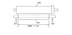
・圧縮永久歪み試験
図4は、実験試料としての導電性発泡ローラの圧縮永久歪み測定方法を説明するための説明図である。同図に示すように、転写ローラに相当する導電性発泡ローラ101を、感光体ドラムに相当する外径30mmの筒型形状部103に対して、押し込み力47gf/cmで圧接して、温度70℃、湿度90%環境下に7日開放置する試験である。
尚、 押し込み力=全荷重÷接触長 であり、A4サイズの場合、接触長に相当するゴム長は214mmで、全荷重は1000gfとする。また、圧接する場合には、例えばバネ等で導電性発泡ローラ101の中心軸を押圧して行う。
・歪み量、永久歪み率
圧縮永久歪み試験を実施して、荷重負荷を解除してから7日経過時点でのゴム部分の長手方向(芯金の軸方向)中央部及び両端から内側10mmの3箇所の圧接位置について残留している歪み量(表に示す値はそれらの平均値)を測定し、その平均値をゴムの厚さで割った値(%表示)を圧縮永久歪み率とした。
Compression Set Test FIG. 4 is an explanatory diagram for explaining a method for measuring compression set of a conductive foam roller as an experimental sample. As shown in the figure, a
In addition, indentation force = total load / contact length. In the case of A4 size, the rubber length corresponding to the contact length is 214 mm, and the total load is 1000 gf. In the case of press contact, for example, the central axis of the
-Strain amount, permanent strain rate 3 of 10 mm inward from the center in the longitudinal direction (axial direction of the cored bar) of the rubber part after 7 days have passed since the compression set test was performed and the load was released. The amount of strain remaining (the values shown in the table are average values thereof) at the pressure contact positions of the places was measured, and a value (in%) obtained by dividing the average value by the rubber thickness was defined as a compression set rate.
・画像評価の方法について
例えば図1の画像形成装置1(タンデム型のカラー電子写真プリンタ)を使用し、その転写ローラ41として、圧縮永久歪み率を測定した各導電性発泡ローラ102を装着して100%画像パターンを印刷して画像品質評価する。転写ローラ41として使用する導電性発泡ローラ102と感光体ドラム21との間は一定加重になるように設定して、両者の押し当て全荷重は1000gfとした。圧縮永久歪み試験において、転写ローラの接触部分の永久歪み率が所定値以上の場合に、感光体ドラム21への接触状態が正常部分と異なってしまう。そのためトナーの転写性が電気的にも機械的にも適正でなくなって画像上の横帯が発生する。画像評価は、この横帯の有無により良否を判定する。表では、良の場合を○で、不良の場合×で示している。
Image Evaluation Method For example, the image forming apparatus 1 (tandem type color electrophotographic printer) shown in FIG. 1 is used, and as the
表3に示す各実験例の導電性発泡ローラについて、圧縮永久歪み試験による永久歪み率測定の結果を表4に示す。同表に示すように、実験例1〜9では、永久歪み率が何れも1.75%以下であり画像は良好であった。実験例10では、永久歪み率が2.09%となって所定値を超え、100%画像の中に転写ローラ周期の横帯が発生した。 Table 4 shows the results of permanent strain rate measurement by a compression set test for the conductive foam rollers of each experimental example shown in Table 3. As shown in the table, in Experimental Examples 1 to 9, the permanent distortion rate was 1.75% or less, and the images were good. In Experimental Example 10, the permanent distortion rate was 2.09%, exceeding a predetermined value, and a horizontal band of the transfer roller period was generated in the 100% image.
従って、実験例1〜9の実施例で示すように、ここでは少なくとも永久歪み率が1.75%以下となる温度と時間で二次加硫を行うことによって、圧縮永久歪み起因する画像上の横帯を防ぐことができる。尚、ここでの実験例10は参考例として掲げるものである。 Therefore, as shown in Examples of Experimental Examples 1 to 9, here, by performing secondary vulcanization at a temperature and a time at which the permanent set rate is at most 1.75%, on the image due to compression set A horizontal band can be prevented. In addition, Experimental example 10 here is listed as a reference example.
一般に、アクリロニトリルブタジエンゴムを多く配合して発泡させたゴム加硫物は、圧縮永久歪みが悪くなるという問題があったが、以上のように、本実施の形態の導電性発泡ローラの製造方法によれば、ゴム加硫物を発泡させてスポンジ状として柔軟性を持たせる場合に、アクリロニトリルブタジエンゴムを多く配合し、環境負荷を軽減する理由のため塩素を含有するエピクロルヒドリンゴムの含有比率を抑えても、圧縮永久歪み率を所定値以下として、圧縮永久歪みに起因する横帯び発生による、印刷の品質劣化を防止することができる。 In general, a rubber vulcanizate obtained by blending and foaming a large amount of acrylonitrile butadiene rubber has a problem that the compression set deteriorates. As described above, the method for producing a conductive foam roller according to the present embodiment is used. According to this, when foaming rubber vulcanizate to give flexibility as a sponge, a large amount of acrylonitrile butadiene rubber is blended, and the content ratio of epichlorohydrin rubber containing chlorine is suppressed for the reason of reducing environmental burden. However, it is possible to prevent the print quality from being deteriorated due to the occurrence of horizontal banding caused by the compression set by setting the compression set rate to a predetermined value or less.
実施の形態2.
(実験例11〜17)
表5に示す、導電性発泡ローラの実験例11〜17に用いた原材料及び配合割合は、表1に示す配合Aである。配合Aからなるゴム混合物を、密閉式混練機(DS10−40MWA−S(株)森山製作所製)により100℃で10分間混練した。上記混練機からリボン取りしたゴム混合物を、40℃に温度調節された単軸押出機に投入して中空チューブ状に押し出した。この時、得られるチューブの寸法を、外径16mm、内径5mm、長さ30mとする。このゴムチューブを適切な長さにカットして予備成形チューブを成形し、この予備成形チューブを加圧式水蒸気式加硫缶に投入して160℃で60分間の一次加硫を行った。この際、化学発泡剤がガス化して発泡すると共に、ゴム成分の架橋も進行した。上記の如く円筒形状の加硫発泡体チューブの中空部に、ホットメルト接着剤を塗布した金属製シャフトからなる芯金(外径6mm)を圧入挿入して、一次成形ローラを得た。
Embodiment 2. FIG.
(Experimental Examples 11-17)
The raw materials and blending ratios used in Experimental Examples 11 to 17 of the conductive foam roller shown in Table 5 are the blend A shown in Table 1. The rubber mixture composed of the blend A was kneaded at 100 ° C. for 10 minutes using a closed kneader (DS10-40MWA-S, manufactured by Moriyama Seisakusho). The rubber mixture ribbon-removed from the kneader was put into a single screw extruder whose temperature was adjusted to 40 ° C. and extruded into a hollow tube shape. At this time, the dimensions of the obtained tube are 16 mm outer diameter, 5 mm inner diameter, and 30 m length. The rubber tube was cut into an appropriate length to form a preformed tube, and the preformed tube was put into a pressurized steam vulcanizer and subjected to primary vulcanization at 160 ° C. for 60 minutes. At this time, the chemical foaming agent gasified and foamed, and the crosslinking of the rubber component also proceeded. A cored bar (outer diameter 6 mm) made of a metal shaft coated with a hot melt adhesive was press-fitted into the hollow part of the cylindrical vulcanized foam tube as described above to obtain a primary molding roller.
次に、一次成形ローラを熱風オーブンに入れ、160℃で60分間の二次加硫を行って、芯金と導電性発泡ゴムとが接着され一体化した後に、ゴム両端を切落としてゴム長を214mmとし、ゴム表面を研磨してゴム厚さ4mmで外径を14mmとして二次成形ローラを得た。ここでは、以上のようにして得られる二次成形ローラを7試料用意し、それぞれを熱風オーブンに入れ、表5に示す7例の温度と時間でアニール処理して、実験例11〜17の導電性発泡ローラを得た。 Next, the primary molding roller is put in a hot air oven, and secondary vulcanization is performed at 160 ° C. for 60 minutes. After the core metal and the conductive foam rubber are bonded and integrated, the rubber ends are cut off to remove the rubber length. Was 214 mm, and the rubber surface was polished to obtain a secondary molding roller having a rubber thickness of 4 mm and an outer diameter of 14 mm. Here, seven samples of the secondary forming roller obtained as described above were prepared, each was put in a hot air oven, and annealed at the temperature and time of the seven examples shown in Table 5 to obtain the conductivity of Experimental Examples 11-17. A foaming roller was obtained.
得られた実験例11〜17の導電性発泡ローラについて、電気抵抗値、抵抗周ムラ、製品硬度を測定した結果を表5に示し、同じく歪み量、歪み率の測定結果、及びべた画像評価の結果を図6に示す。尚、表5の各パラメータ、そして表6の圧縮永久歪み率の試験方法、及び画像評価の方法については、前記した実施の形態1で説明した通りなので、ここでの説明は省略する。 The results of measuring the electrical resistance value, resistance circumferential unevenness, and product hardness of the obtained conductive foam rollers of Experimental Examples 11 to 17 are shown in Table 5, and similarly, the amount of distortion, the measurement result of the distortion rate, and the solid image evaluation The results are shown in FIG. The parameters shown in Table 5 and the compression set test method and image evaluation method shown in Table 6 are the same as those described in the first embodiment, and a description thereof is omitted here.
表6に示すように、実験例12〜16では永久歪み率が1.63%以下で画像は良好であった。実験例11及び実験例17では、永久歪み率が1.98%及び1.9%となり、100%画像の中に転写ローラ周期の横帯が発生した。 As shown in Table 6, in Experimental Examples 12 to 16, the permanent distortion rate was 1.63% or less, and the images were good. In Experimental Example 11 and Experimental Example 17, the permanent distortion rates were 1.98% and 1.9%, and a horizontal band of the transfer roller period was generated in the 100% image.
従って、実験例12〜16の実施例で示すように、ここでは少なくとも永久歪み率が1.63%以下となる温度と時間でアニール処理を行うことによって、圧縮永久歪み起因する画像上の横帯を防ぐことができる。尚、ここでの実験例11,17は参考例として掲げるものである。 Therefore, as shown in Examples of Experimental Examples 12 to 16, here, the horizontal band on the image caused by the compression set is obtained by performing the annealing process at a temperature and a time at which the set rate is at most 1.63% or less. Can be prevented. Note that Experimental Examples 11 and 17 are provided as reference examples.
(実験例18〜23)
表7に示す、導電性発泡ローラの実験例18〜23に用いた原材料及び配合割合は、表1に示す配合Bである。ここでは、実験例11〜17と同じ製造方法で、即ち配合Bからなるゴム混合物を、100℃で10分間混練して中空チューブ状に押出して予備成形チューブを成形した後、160℃で60分間の一次加硫、及び160℃で60分間の二次加硫を行って二次成形ローラを6試料用意し、それぞれを熱風オーブンに入れ、表7に示す6例の温度と時間でアニール処理して、実験例18〜23の導電性発泡ローラを得た。
(Experimental Examples 18-23)
The raw materials and blending ratios used in Experimental Examples 18 to 23 of the conductive foam roller shown in Table 7 are blend B shown in Table 1. Here, the same manufacturing method as in Experimental Examples 11 to 17, ie, a rubber mixture composed of compounding B was kneaded at 100 ° C. for 10 minutes and extruded into a hollow tube to form a preformed tube, and then at 160 ° C. for 60 minutes. 6 samples of secondary forming rollers were prepared by performing primary vulcanization and secondary vulcanization at 160 ° C. for 60 minutes, and each sample was put in a hot air oven and annealed at the temperature and time of 6 examples shown in Table 7. Thus, conductive foam rollers of Experimental Examples 18 to 23 were obtained.
得られた実験例18〜23の導電性発泡ローラについて、電気抵抗値、抵抗周ムラ、製品硬度を測定した結果を表7に示し、同じく歪み量、歪み率の測定結果、及びべた画像評価の結果を図8に示す。 Table 7 shows the results of measuring the electrical resistance value, resistance circumferential unevenness, and product hardness of the obtained conductive foam rollers of Experimental Examples 18 to 23. Similarly, the distortion amount, the measurement result of the distortion rate, and the solid image evaluation The results are shown in FIG.
表8に示すように、実験例19〜22では永久歪み率が1.58%以下で画像は良好であった。実験例18及び実験例23では、永久歪み率が1.92%及び1.88%となり、100%画像の中に転写ローラ周期の横帯が発生した。 As shown in Table 8, in Experimental Examples 19 to 22, the permanent distortion rate was 1.58% or less, and the images were good. In Experimental Example 18 and Experimental Example 23, the permanent distortion ratios were 1.92% and 1.88%, and horizontal bands of the transfer roller period were generated in the 100% image.
従って、実験例19〜22の実施例で示すように、ここでは少なくとも永久歪み率が1.58%以下となる温度と時間でアニール処理を行うことによって、圧縮永久歪み起因する画像上の横帯を防ぐことができる。尚、ここでの実験例18,23は参考例として掲げるものである。 Therefore, as shown in Examples of Experimental Examples 19 to 22, here, by performing annealing treatment at a temperature and time at which the permanent set rate is at least 1.58% or less, the horizontal band on the image caused by compression set is obtained. Can be prevented. Note that Experimental Examples 18 and 23 are provided as reference examples.
(実験例24〜29)
表9に示す、導電性発泡ローラの実験例24〜29に用いた原材料及び配合割合は、表1に示す配合Cである。ここでは、実験例11〜17と同じ製造方法で、即ち配合Cからなるゴム混合物を、100℃で10分間混練して中空チューブ状に押出して予備成形チューブを成形した後、160℃で60分間の一次加硫、及び160℃で60分間の二次加硫を行って二次成形ローラを6試料用意し、それぞれを熱風オーブンに入れ、表9に示す6例の温度と時間でアニール処理して、実験例24〜29の導電性発泡ローラを得た。
(Experimental Examples 24-29)
The raw materials and blending ratios used in Experimental Examples 24 to 29 of the conductive foam roller shown in Table 9 are the blend C shown in Table 1. Here, the same manufacturing method as in Experimental Examples 11 to 17, that is, a rubber mixture composed of compounding C was kneaded at 100 ° C. for 10 minutes and extruded into a hollow tube to form a preformed tube, and then at 160 ° C. for 60 minutes. 6 samples of secondary forming rollers were prepared by performing primary vulcanization and secondary vulcanization at 160 ° C. for 60 minutes, and each sample was put in a hot air oven and annealed at the temperature and time of 6 examples shown in Table 9. Thus, conductive foam rollers of Experimental Examples 24 to 29 were obtained.
得られた実験例24〜29の導電性発泡ローラについて、電気抵抗値、抵抗周ムラ、製品硬度を測定した結果を表9に示し、同じく歪み量、歪み率の測定結果、及びべた画像評価の結果を図10に示す。 Table 9 shows the results of measuring the electrical resistance value, resistance circumferential unevenness, and product hardness of the obtained conductive foam rollers of Experimental Examples 24 to 29. Similarly, the results of measurement of distortion amount, distortion rate, and solid image evaluation The results are shown in FIG.
表10に示すように、実験例25〜28では永久歪み率が1.55%以下で画像は良好であった。実験例24及び実験例29では、永久歪み率が1.90%及び1.88%となり、100%画像の中に転写ローラ周期の横帯が発生した。 As shown in Table 10, in Experimental Examples 25 to 28, the permanent distortion rate was 1.55% or less, and the image was good. In Experimental Example 24 and Experimental Example 29, the permanent distortion ratios were 1.90% and 1.88%, and the horizontal band of the transfer roller period was generated in the 100% image.
従って、実験例25〜28の実施例で示すように、ここでは少なくとも永久歪み率が1.55%以下となる温度と時間でアニール処理を行うことによって、圧縮永久歪み起因する画像上の横帯を防ぐことができる。尚、ここでの実験例24,29は参考例として掲げるものである。 Accordingly, as shown in Examples of Experimental Examples 25 to 28, here, the horizontal band on the image due to compression set is obtained by performing annealing treatment at a temperature and time at which the set rate is at least 1.55% or less. Can be prevented. Here, Experimental Examples 24 and 29 are provided as reference examples.
以上のように、本実施の形態の導電性発泡ローラの製造方法によれば、実施の形態1の場合と同様に、ゴム加硫物を発泡させてスポンジ状として柔軟性を持たせる場合に、アクリロニトリルブタジエンゴムを多く配合し、環境負荷を軽減する理由のため塩素を含有するエピクロルヒドリンゴムの含有比率を抑えても、圧縮永久歪み率を所定値以下として、圧縮永久歪み起因する横帯び発生による、印刷の品質劣化を防止することができる。
更に、多くの実験例で永久歪み率を1.63%以下とすることができたように、実施の形態1の場合よりも、更に永久歪み率を引き下げることが容易となり、品質の向上及び生産性の向上に寄与できる。
As described above, according to the method of manufacturing the conductive foam roller of the present embodiment, as in the case of the first embodiment, when the rubber vulcanizate is foamed to have flexibility as a sponge, Even if the content ratio of the epichlorohydrin rubber containing chlorine is reduced for the reason of reducing the environmental load by blending a lot of acrylonitrile butadiene rubber, the compression set rate is set to a predetermined value or less, due to the occurrence of horizontal band caused by compression set, Printing quality deterioration can be prevented.
Further, as in many experimental examples, the permanent distortion rate could be 1.63% or less, it becomes easier to lower the permanent distortion rate than in the case of the first embodiment, thereby improving quality and production. It can contribute to the improvement of sex.
実施の形態3.
(実験例30)
実験例30では、前記した実施の形態1の実験例5の実験試料である導電性発泡ローラに対して、研磨による外径が僅かに異なる導電性発泡ローラを得る。即ち、実施の形態1で示した導電性発泡ローラの実験例1〜10と同様の方法で、一次成形ローラを得て熱風オーブンに入れ、表3に示す実験例5の場合と同様に、温度130℃にて3時間の二次加硫を行った。そして、芯金と導電性発泡ゴムとが接着され一体化した後に、ゴム両端を切落としてゴム長を214mmとしてゴム表面を研磨し、ここではゴム厚さが4mm〜4.1mmで、ゴム端部の外径を14mm、ゴム中央部の外径を14.1mmとして、外径差100μmとなる略太鼓形状を狙った。
Embodiment 3 FIG.
(Experiment 30)
In Experimental Example 30, a conductive foaming roller having a slightly different outer diameter by polishing is obtained with respect to the conductive foaming roller that is the experimental sample of Experimental Example 5 of
図5は、本実施の形態の導電性発泡ローラの理想的な外周面の形状を示す正面図である。同図に示すように、理想的な導電性発泡ローラは、そのゴム部111(図中110は芯金)の断面外形線が4次曲線に沿って形成されて、外周面が太鼓状に形成されている。図6は、図5の理想形状に近似させるため、中央部付近を円柱形状とし、その両側を円錐台形状とした近似形状の例を示す実験例30の導電性発泡ローラの簡易図である。 FIG. 5 is a front view showing an ideal shape of the outer peripheral surface of the conductive foam roller of the present embodiment. As shown in the figure, an ideal conductive foaming roller has a rubber section 111 (110 in the figure is a metal core) whose cross-sectional outline is formed along a quartic curve and whose outer peripheral surface is formed in a drum shape. Has been. FIG. 6 is a simplified diagram of the conductive foam roller of Experimental Example 30 showing an example of an approximate shape in which the vicinity of the center is a cylinder shape and both sides thereof are truncated cone shapes so as to approximate the ideal shape of FIG.
図7は、図6の近似形状の構成を説明するための説明図である。同図(a)に示すように、理想形状(その半径の変化を点線で示す)のゴム部分と同じ体積であるように円錐台を選択し、半径7.05mmを超える部分をカットして同図(b)の形状を得るものである。図15は、図7(b)の形状を目標にして研磨して得た実験例30の導電性発泡ローラの外径を測定した測定結果を示すグラフである。このように外径差90μmの導電性発泡ローラを得た。 FIG. 7 is an explanatory diagram for explaining the configuration of the approximate shape of FIG. As shown in the figure (a), the truncated cone is selected so that it has the same volume as the rubber part of the ideal shape (the change in radius is indicated by a dotted line), and the part exceeding the radius of 7.05 mm is cut and the same. The shape shown in FIG. FIG. 15 is a graph showing measurement results obtained by measuring the outer diameter of the conductive foam roller of Experimental Example 30 obtained by polishing with the shape of FIG. 7B as a target. Thus, a conductive foaming roller having an outer diameter difference of 90 μm was obtained.
表11は、この実験例30における圧縮永久歪み試験の測定結果と画像評価結果を示す。尚、表11の圧縮永久歪み率の試験方法、及び画像評価の方法については、前記した実施の形態1で説明した通りなので、ここでの説明は省略する。同表に示すように、ここでは永久歪み率が1.32%となり、画像は良好であった。 Table 11 shows the measurement results and image evaluation results of the compression set test in Experimental Example 30. The compression set test method and the image evaluation method shown in Table 11 are the same as those described in the first embodiment, and a description thereof is omitted here. As shown in the table, the permanent distortion rate was 1.32%, and the image was good.
図15に示すグラフでは、ゴム端部から10mm未満の領域の形状が理想的ではないが問題ではない。なぜならゴム端部から10mm未満の領域については、ゴムの非圧縮性によりゴムが外側に逃げてしまうため、狙いの外径に研磨できないのが実情であって、また使用時にも被接触物に対してゴム端部は同様に外側へ逃げるため、ゴム端部から10mm未満の領域の形状を重要に捉えなくても問題ない。 In the graph shown in FIG. 15, the shape of the region less than 10 mm from the rubber end is not ideal, but it is not a problem. Because, in the region of less than 10 mm from the rubber end, the rubber escapes to the outside due to the incompressibility of the rubber, so the actual situation is that it cannot be polished to the target outer diameter. Since the rubber end portion escapes to the outside in the same manner, there is no problem even if the shape of the region of less than 10 mm from the rubber end portion is not important.
以上のように、本実施の形態の実施例(実験例30)による導電性発泡ローラによれば、実験例5(表3,4)の導電性発泡ローラの永久歪み率1.54%に対して、ゴム部形状を略太鼓上に形成することにより永久歪み率1.32%が得られたように、永久歪み率の低減に寄与することができる。 As described above, according to the conductive foam roller according to the example of the present embodiment (Experimental example 30), the permanent deformation rate of the conductive foam roller of Experimental Example 5 (Tables 3 and 4) is 1.54%. Thus, by forming the rubber part shape substantially on the drum, it is possible to contribute to the reduction of the permanent distortion rate as the permanent distortion rate of 1.32% is obtained.
実施の形態4.
表12に示す、導電性発泡ローラの実験例31、32に用いた原材料及び配合割合は、表1に示す配合Bである。配合Bからなるゴム混合物を、密閉式混練機(DS10−40MWA−S(株)森山製作所製)により100℃で10分間混練した。上記混練機からリボン取りしたゴム混合物を、40℃に温度調節された単軸押出機に投入して中空チューブ状に押し出した。この時、得られるチューブの寸法を、外径20mm、内径7mm、長さ30mとする。このゴムチューブを適切な長さにカットして予備成形チューブを成形し、この予備成形チューブを加圧式水蒸気式加硫缶に投入して160℃で60分間の一次加硫をおこなった。この際、化学発泡剤がガス化して発泡すると共に、ゴム成分の架橋も進行した。上記の如く円筒形状の加硫発泡体チューブの中空部に、ホットメルト接着剤を塗布した金属製シャフトからなる芯金(外径8mm)を圧入挿入して、一次成形ローラを得た。
Embodiment 4 FIG.
The raw materials and blending ratios used in Experimental Examples 31 and 32 of the conductive foam roller shown in Table 12 are the blends B shown in Table 1. The rubber mixture composed of the blend B was kneaded at 100 ° C. for 10 minutes with a closed kneader (DS10-40MWA-S, manufactured by Moriyama Seisakusho). The rubber mixture ribbon-removed from the kneader was put into a single screw extruder whose temperature was adjusted to 40 ° C. and extruded into a hollow tube shape. At this time, the dimensions of the obtained tube are 20 mm in outer diameter, 7 mm in inner diameter, and 30 m in length. The rubber tube was cut into an appropriate length to form a preformed tube, and the preformed tube was put into a pressurized steam vulcanizing can and subjected to primary vulcanization at 160 ° C. for 60 minutes. At this time, the chemical foaming agent gasified and foamed, and the crosslinking of the rubber component also proceeded. As described above, a cored bar (outer diameter: 8 mm) made of a metal shaft coated with a hot-melt adhesive was press-inserted into the hollow part of the cylindrical vulcanized foam tube to obtain a primary forming roller.
一次成形ローラを熱風オーブンに入れ、温度130℃にて3時間(実験例5に相当)の二次加硫を行って、芯金と導電性発泡ゴムとが接着され一体化した後に、ゴム両端を切落としてゴム長をA3サイズ対応の301mmにしてゴム表面を研磨し、ここでは実験例31、32の何れも、ゴム端部の外径を16mm、ゴム中央部の外径を16.2mmとして、外径差200μmとなる略太鼓形状を狙った。 Place the primary molding roller in a hot air oven, perform secondary vulcanization for 3 hours (corresponding to Experimental Example 5) at a temperature of 130 ° C., and the core metal and conductive foam rubber are bonded and integrated, And the rubber surface is polished to 301 mm corresponding to the A3 size, and the rubber surface is polished. In each of Experimental Examples 31 and 32, the outer diameter of the rubber end portion is 16 mm and the outer diameter of the rubber central portion is 16.2 mm. As an example, a substantially drum shape with an outer diameter difference of 200 μm was aimed.
(実験例31)
図8は、本実施の形態の導電性発泡ローラの理想的な外周面の形状を示す正面図である。同図に示すように、理想的な導電性発泡ローラは、そのゴム部111(図中110は芯金)の断面外形線が4次曲線に沿って形成されて、外周面が太鼓状に形成されている。図9は、図8の理想形状に近似させるため、中央部付近を円柱形状とし、その両側を円錐台形状とした近似形状の例を示す実験例31の導電性発泡ローラの簡易図である。
(Experimental example 31)
FIG. 8 is a front view showing an ideal shape of the outer peripheral surface of the conductive foam roller of the present embodiment. As shown in the figure, an ideal conductive foaming roller has a rubber section 111 (110 in the figure is a metal core) whose cross-sectional outline is formed along a quartic curve and whose outer peripheral surface is formed in a drum shape. Has been. FIG. 9 is a simplified diagram of the conductive foam roller of Experimental Example 31 showing an example of an approximate shape in which the vicinity of the center portion is a columnar shape and both sides thereof are frustoconical in order to approximate the ideal shape of FIG.
図10は、図9の近似形状の構成を説明するための説明図である。前記した実験例30の場合と同様に、先ず理想形状(その半径の変化を点線で示す)のゴム部分と同じ体積であるように円錐台を選択し、半径8.10mmを超える部分をカットして同図の形状を得るものである。図16は、図10の形状を目標にして研磨して得た実験例31の導電性発泡ローラの外径を測定した測定結果を示すグラフである。このように外径差186μmの導電性発泡ローラを得た。 FIG. 10 is an explanatory diagram for explaining the configuration of the approximate shape of FIG. As in the case of the experimental example 30 described above, the truncated cone is first selected so as to have the same volume as the rubber portion of the ideal shape (change in radius is indicated by a dotted line), and the portion exceeding the radius of 8.10 mm is cut. Thus, the shape shown in FIG. FIG. 16 is a graph showing measurement results obtained by measuring the outer diameter of the conductive foam roller of Experimental Example 31 obtained by polishing with the shape of FIG. 10 as a target. Thus, a conductive foaming roller having an outer diameter difference of 186 μm was obtained.
表12に、この実験例31における圧縮永久歪み試験の測定結果と画像評価結果を示す。このように、ここでは永久歪み率が1.80%となり、100%画像の中に転写ローラ周期の横帯が発生した。以上のように、ここでの実験例31は、参考例として掲げたものである。 Table 12 shows the measurement results and the image evaluation results of the compression set test in Experimental Example 31. As described above, the permanent distortion rate is 1.80%, and a horizontal band of the transfer roller period is generated in the 100% image. As described above, Experimental Example 31 here is provided as a reference example.
(実験例32)
図11は、図8の理想形状に近似させた実験例32の導電性発泡ローラの簡易図である。同図に示すように、ここでの導電性発泡ローラのゴム部111は、芯金110の軸方向における中央部を中心に左右対称に形成され、中央部付近を円柱形状とし、例えば一方の側において、端部に向かって2種類の円錐台2、円錐台21を段差が生じないように連ねて近似している。同図中の円錐台1と2との境界位置は、ゴム端部から内側に10mmの位置から、ゴム端部から内側にゴム全長の28%までの場所が良い。以下にその理由を説明する。
(Experimental example 32)
FIG. 11 is a simplified diagram of the conductive foam roller of Experimental Example 32 approximated to the ideal shape of FIG. As shown in the figure, the
図12は、円柱部分が無くて円錐台1と2のみで表す場合を説明するための説明図である。理想と考える4次曲線に対して、最適化した円錐台を選択するために、体積差が極小になるような境界位置を求める。これは、S−S1およびS−S2の和が極小になることと等価であるので、
△((S−S1)十(S−S2))=MIN(極小値)
である。上記変分方程式を満足する境界位置は、ゴム端部から内側に85mmの場所であり、図13は、境界位置をこの85mmの位置に設定した状態を示す説明図である。この時の境界位置は、ゴム部全長(301mm)の約28%に相当する。更に円柱部分がある場合は、上記境界位置が端部側ヘシフトするため、上記境界位置はゴム端部から内側にゴム全長の28%までの場所に設定されることが望ましい。図14はこの時の状態、即ち実験例32の近似形状を示している。
FIG. 12 is an explanatory diagram for explaining a case where there is no cylindrical portion and only the
Δ ((S−S1) + (S−S2)) = MIN (minimum value)
It is. The boundary position satisfying the variation equation is a place 85 mm inward from the rubber end, and FIG. 13 is an explanatory diagram showing a state where the boundary position is set to the 85 mm position. The boundary position at this time corresponds to about 28% of the total length of the rubber part (301 mm). Further, when there is a cylindrical portion, the boundary position is shifted to the end side, and therefore, the boundary position is preferably set at a location up to 28% of the total length of the rubber from the rubber end. FIG. 14 shows the state at this time, that is, the approximate shape of Experimental Example 32.
図17は、図14に示す形状を目標として研磨して得た実験例32の導電性発泡ローラの外径を測定した測定結果を示すグラフである。このようにして外径差180μmの導電性発泡ローラを得た。尚、ゴム端部から10mm未満の領域の形状が理想的ではないが、実験例30で説明した理由と同様の理由により問題ない。 FIG. 17 is a graph showing measurement results obtained by measuring the outer diameter of the conductive foam roller of Experimental Example 32 obtained by polishing the shape shown in FIG. 14 as a target. Thus, a conductive foam roller having an outer diameter difference of 180 μm was obtained. The shape of the region less than 10 mm from the rubber end is not ideal, but there is no problem for the same reason as described in Experimental Example 30.
表12に、この実験例32における圧縮永久歪み試験の測定結果と画像評価結果を示す。このように、ここでは永久歪み率が1.55%となり、画像は良好であった。 Table 12 shows the measurement results and image evaluation results of the compression set test in Experimental Example 32. Thus, the permanent distortion rate was 1.55% here, and the image was good.
図18は、感光体ドラム21(図1)或いは感光体ドラム21に相当する筒型形状部103(図4)に対する、図9に外形を示す実験例31の導電性発泡ローラのニップ量を示すグラフであり、図19は、同じく感光体ドラム21或いは筒型形状部103に対する、図11に外形を示す実験例32の導電性発泡ローラのニップ量を示すグラフである。
18 shows the nip amount of the conductive foam roller of Experimental Example 31 whose outer shape is shown in FIG. 9 with respect to the photosensitive drum 21 (FIG. 1) or the cylindrical shape portion 103 (FIG. 4) corresponding to the
図18のグラフに示すように、実験例31(参考例)の導電性発泡ローラでは、端部付近への荷重が強く、中間部分は少し弱まり、中央部で再度強くなっており、A3サイズで全長が長くなったため実験例30と同様なテーパー形状は十分な効果を上げていない。一方図19のグラフに示すように、実験例32(実施例)の導電性発泡ローラでは、実験例31において荷重が端部に集中していた傾向を改善しているので、永久歪みを小さくすることができた。尚、実験例32では現実の量産製造用研磨装置の都合によって二種類の円錐台のみで理想と考える4次曲線を近似しているけれども、多くの円錐台で近似することが望ましい。その理由は上記の如く4次曲線に対する体積差をさらに小さくすることが可能になるからである。 As shown in the graph of FIG. 18, in the conductive foam roller of Experimental Example 31 (reference example), the load near the end is strong, the middle part is slightly weakened, and is strong again in the central part. Since the total length is long, the tapered shape similar to Experimental Example 30 does not provide a sufficient effect. On the other hand, as shown in the graph of FIG. 19, in the conductive foam roller of Experimental Example 32 (Example), the tendency that the load was concentrated on the end portion in Experimental Example 31 was improved, so the permanent distortion was reduced. I was able to. In Experimental Example 32, an ideal quartic curve is approximated with only two types of truncated cones due to the convenience of an actual mass production polishing apparatus, but it is desirable to approximate with many truncated cones. This is because the volume difference with respect to the quartic curve can be further reduced as described above.
以上のように本実施の形態の導電性発泡ローラによれば、そのゴム部を複数の円錐台を段差無く連続して配置した構成にして理想形状に近似させることによって永久歪み率の低減を実現している。このため、A3対応のようにサイズが大きくて、永久歪み率の低減が難しくなる転写ローラに用いて好適な導電性発泡ローラを提供できる。 As described above, according to the conductive foam roller of the present embodiment, the permanent deformation rate is reduced by approximating the rubber part to an ideal shape by arranging a plurality of truncated cones continuously without steps. is doing. Therefore, it is possible to provide a conductive foam roller suitable for use in a transfer roller that is large in size as in A3 and difficult to reduce the permanent distortion rate.
1 画像形成装置、
11〜14 イメージドラムユニット、
16 記録用紙、
21 感光体ドラム、
22 帯電ローラ、
23 LEDヘッド、
24 現像ローラ、
25,48 クリーニングブレード、
26 トナーカートリッジ、
30 レジストローラユニット、
37 給紙カセット、
38 定着ユニット、
39 排紙トレイ、
40 転写部、
41 転写ローラ、
42 搬送ベルト、
43 ドライブローラ、
44〜46 テンションローラ、
51 芯金、
52 発泡ゴム層、
101 回転ドラム、
102 導電性発泡ローラ、
103 筒型形状部、
110 芯金、
111 ゴム部。
1 image forming apparatus,
11-14 Image drum unit,
16 recording paper,
21 photosensitive drum,
22 charging roller,
23 LED head,
24 Development roller,
25, 48 Cleaning blade,
26 toner cartridge,
30 registration roller unit,
37 Paper cassette,
38 fixing unit,
39 Output tray,
40 Transfer section,
41 transfer roller,
42 Conveyor belt,
43 Drive roller,
44-46 tension roller,
51 mandrel,
52 foam rubber layer,
101 rotating drum,
102 conductive foam roller,
103 cylindrical shape part,
110 Core,
111 Rubber part.
Claims (18)
圧縮永久歪み率が1.75%以下であることを特徴とする導電性発泡ローラ。 In the conductive foam roller provided with the core metal and the conductive foam rubber,
A conductive foam roller having a compression set of 1.75% or less.
アクリロニトリルブタジエンゴムとエピクロルヒドリンゴムを所定の配合割合で混練する工程と、
前記混練したゴム混合物を中空チューブ状に押し出し、所定の長さにカットして予備成形チューブを成形する工程と、
前記予備成形チューブを略160℃で60分間程度の一次加硫を行う工程と、
前記一次加硫を行った前記予備成形チューブの中空部に芯金を圧入して一次成形ローラを得る工程と、
前記一次成形ローラを所定の温度と時間で二次加硫を行う工程と、
前記二次加硫を行った前記一次成形ローラを所定の形状に研磨する工程と
を有することを特徴とする導電性発泡ローラの製造方法。 In a method of manufacturing a conductive foam roller provided with a core metal and conductive foam rubber,
A step of kneading acrylonitrile butadiene rubber and epichlorohydrin rubber in a predetermined blending ratio;
Extruding the kneaded rubber mixture into a hollow tube shape, cutting it into a predetermined length and forming a preformed tube;
Performing the primary vulcanization of the preformed tube at about 160 ° C. for about 60 minutes;
A step of press-fitting a core metal into the hollow portion of the preformed tube that has undergone the primary vulcanization to obtain a primary molding roller;
Performing a secondary vulcanization of the primary molding roller at a predetermined temperature and time;
And a step of polishing the primary molding roller subjected to the secondary vulcanization into a predetermined shape.
アクリロニトリルブタジエンゴムとエピクロルヒドリンゴムを所定の配合割合で混練する工程と、
前記混練したゴム混合物を中空チューブ状に押し出し、所定の長さにカットして予備成形チューブを成形する工程と、
前記予備成形チューブを略160℃で60分間程度の一次加硫を行う工程と、
前記一次加硫を行った前記予備成形チューブの中空部に芯金を圧入して一次成形ローラを得る工程と、
前記一次成形ローラを略160℃で60分間程度の二次加硫を行う工程と、
前記二次加硫を行った前記一次成形ローラを所定の形状に研磨して二次成形ローラを得る工程と、
前記二次成形ローラを所定の温度と時間でアニールする工程と
を有することを特徴とする導電性発泡ローラの製造方法。 In a method of manufacturing a conductive foam roller provided with a core metal and conductive foam rubber,
A step of kneading acrylonitrile butadiene rubber and epichlorohydrin rubber in a predetermined blending ratio;
Extruding the kneaded rubber mixture into a hollow tube shape, cutting it into a predetermined length and forming a preformed tube;
Performing the primary vulcanization of the preformed tube at about 160 ° C. for about 60 minutes;
A step of press-fitting a core metal into the hollow portion of the preformed tube that has undergone the primary vulcanization to obtain a primary molding roller;
Performing the secondary vulcanization of the primary molding roller at about 160 ° C. for about 60 minutes;
Polishing the primary vulcanization roller that has undergone the secondary vulcanization into a predetermined shape to obtain a secondary molding roller;
And a step of annealing the secondary forming roller at a predetermined temperature and time.
ゴム部が、前記芯金の軸方向における、中央部から両端部近傍にかけて、外径が漸次小さくなる領域を有することを特徴とする導電性発泡ローラ。 A conductive foam roller manufactured by the method of manufacturing a conductive foam roller according to any one of claims 4 to 13,
The conductive foam roller, wherein the rubber portion has a region where the outer diameter gradually decreases from the center portion to the vicinity of both end portions in the axial direction of the cored bar.
前記感光体ドラムに直接或いは間接的に圧接して配置され、前記トナー像を記録媒体に転写するよう電圧を印加する転写ローラと
を有する画像形成装置において、
前記転写ローラを、請求項1乃至3、及び請求項14乃至16の何れかの導電性発泡ローラとしたことを特徴とする画像形成装置。 A photoreceptor drum carrying a toner image;
An image forming apparatus comprising: a transfer roller that is disposed in direct or indirect contact with the photosensitive drum and applies a voltage to transfer the toner image to a recording medium;
An image forming apparatus, wherein the transfer roller is a conductive foam roller according to any one of claims 1 to 3 and claims 14 to 16.
前記感光体ドラムに直接或いは間接的に圧接して配置され、前記トナー像を記録媒体に転写するよう電圧を印加する転写ローラと
を有する画像形成装置において、
前記転写ローラを、請求項4乃至13の何れかの導電性発泡ローラの製造方法で製造された導電性発泡ローラとしたことを特徴とする画像形成装置。 A photoreceptor drum carrying a toner image;
An image forming apparatus comprising: a transfer roller that is disposed in direct or indirect contact with the photosensitive drum and applies a voltage to transfer the toner image to a recording medium;
An image forming apparatus, wherein the transfer roller is a conductive foam roller manufactured by the method of manufacturing a conductive foam roller according to claim 4.
Priority Applications (2)
| Application Number | Priority Date | Filing Date | Title |
|---|---|---|---|
| JP2006235642A JP2008058621A (en) | 2006-08-31 | 2006-08-31 | Conductive foam roller, method for manufacturing conductive foam roller and image forming apparatus |
| US11/892,472 US20080056766A1 (en) | 2006-08-31 | 2007-08-23 | Conductive foamed roller, method of producing the same, and image forming apparatus |
Applications Claiming Priority (1)
| Application Number | Priority Date | Filing Date | Title |
|---|---|---|---|
| JP2006235642A JP2008058621A (en) | 2006-08-31 | 2006-08-31 | Conductive foam roller, method for manufacturing conductive foam roller and image forming apparatus |
Publications (2)
| Publication Number | Publication Date |
|---|---|
| JP2008058621A true JP2008058621A (en) | 2008-03-13 |
| JP2008058621A5 JP2008058621A5 (en) | 2008-09-04 |
Family
ID=39151713
Family Applications (1)
| Application Number | Title | Priority Date | Filing Date |
|---|---|---|---|
| JP2006235642A Pending JP2008058621A (en) | 2006-08-31 | 2006-08-31 | Conductive foam roller, method for manufacturing conductive foam roller and image forming apparatus |
Country Status (2)
| Country | Link |
|---|---|
| US (1) | US20080056766A1 (en) |
| JP (1) | JP2008058621A (en) |
Cited By (4)
| Publication number | Priority date | Publication date | Assignee | Title |
|---|---|---|---|---|
| JP2010002628A (en) * | 2008-06-19 | 2010-01-07 | Oki Data Corp | Transfer member and image forming apparatus |
| JP2011154083A (en) * | 2010-01-26 | 2011-08-11 | Fuji Xerox Co Ltd | Circular member, electrifying apparatus, image forming apparatus and method for manufacturing circular member |
| JP2015184472A (en) * | 2014-03-24 | 2015-10-22 | 富士ゼロックス株式会社 | Charging member and manufacturing method of the same, process cartridge, and image forming apparatus |
| US11576837B2 (en) | 2019-10-03 | 2023-02-14 | Jfxd Trx Acq Llc | Multi-zonal roller and method of use thereof |
Families Citing this family (4)
| Publication number | Priority date | Publication date | Assignee | Title |
|---|---|---|---|---|
| JP4451906B2 (en) | 2005-02-14 | 2010-04-14 | キヤノン化成株式会社 | Method for producing conductive rubber roller and roller for electrophotographic apparatus |
| US8200136B2 (en) * | 2010-08-26 | 2012-06-12 | Xerox Corporation | Image transfer roller (ITR) utilizing an elastomer crown |
| KR101423856B1 (en) * | 2010-10-13 | 2014-07-25 | 도카이 고무 고교 가부시키가이샤 | Flexible conductive material and transducer, flexible circuit board, and electromagnetic shield using said flexible conductive material |
| JP2016157014A (en) * | 2015-02-25 | 2016-09-01 | シンジーテック株式会社 | Conductive roll, and manufacturing method of the same |
Family Cites Families (5)
| Publication number | Priority date | Publication date | Assignee | Title |
|---|---|---|---|---|
| US5995792A (en) * | 1993-08-04 | 1999-11-30 | Samsung Electronics Co., Ltd. | Developing roll device of an electrophotographic processor for preventing frictional erosion of the developing roll in surface portions thereof |
| JP3805563B2 (en) * | 1998-08-21 | 2006-08-02 | 株式会社リコー | Developing roller, manufacturing method thereof, image forming apparatus using the same, developing unit used therefor, process unit |
| JP4298410B2 (en) * | 2002-08-19 | 2009-07-22 | キヤノン株式会社 | Image heating apparatus and pressure roller used in the apparatus |
| KR100996727B1 (en) * | 2002-11-15 | 2010-11-25 | 스미토모 고무 고교 가부시키가이샤 | Conductive roller and image forming apparatus equipped with the same |
| JP2005316443A (en) * | 2004-03-30 | 2005-11-10 | Canon Inc | Image-heating device and conveyance roller used for the device |
-
2006
- 2006-08-31 JP JP2006235642A patent/JP2008058621A/en active Pending
-
2007
- 2007-08-23 US US11/892,472 patent/US20080056766A1/en not_active Abandoned
Cited By (4)
| Publication number | Priority date | Publication date | Assignee | Title |
|---|---|---|---|---|
| JP2010002628A (en) * | 2008-06-19 | 2010-01-07 | Oki Data Corp | Transfer member and image forming apparatus |
| JP2011154083A (en) * | 2010-01-26 | 2011-08-11 | Fuji Xerox Co Ltd | Circular member, electrifying apparatus, image forming apparatus and method for manufacturing circular member |
| JP2015184472A (en) * | 2014-03-24 | 2015-10-22 | 富士ゼロックス株式会社 | Charging member and manufacturing method of the same, process cartridge, and image forming apparatus |
| US11576837B2 (en) | 2019-10-03 | 2023-02-14 | Jfxd Trx Acq Llc | Multi-zonal roller and method of use thereof |
Also Published As
| Publication number | Publication date |
|---|---|
| US20080056766A1 (en) | 2008-03-06 |
Similar Documents
| Publication | Publication Date | Title |
|---|---|---|
| JP2008058621A (en) | Conductive foam roller, method for manufacturing conductive foam roller and image forming apparatus | |
| JP5998472B2 (en) | Conductive roll, image forming apparatus, and process cartridge | |
| KR101185676B1 (en) | Transfer roller | |
| JP5459101B2 (en) | Annular member, charging device, process cartridge, and image forming apparatus | |
| JP2009151168A (en) | Conductive rubber roller and transfer roller | |
| US9715192B2 (en) | Semiconductive roller, method for manufacturing the same and image forming apparatus | |
| JP4350143B2 (en) | Conductive rubber roller, transfer roller, and image forming apparatus | |
| KR102033823B1 (en) | Developing apparatus, process cartridge and electrophotographic image forming apparatus | |
| JP6730807B2 (en) | Electrophotographic roller, manufacturing method thereof, and electrophotographic image forming apparatus | |
| JP2008058552A (en) | Elastic roller, transfer unit and image forming apparatus | |
| JP2007328025A (en) | Conductive rubber roller, process cartridge provided with it and image forming apparatus | |
| JP2005284295A (en) | Semiconductive roller | |
| JP5002959B2 (en) | Semiconductive belt and image forming apparatus provided with the semiconductive belt | |
| JP2011164179A (en) | Toner-supplying roller and method of producing the same | |
| JP5057504B2 (en) | Conductive rubber member, transfer member and transfer roller | |
| JP2008298855A (en) | Image forming apparatus | |
| JP3886722B2 (en) | Conductive polymer elastic composition | |
| JP2009151001A (en) | Conductive rubber roller and color image forming apparatus | |
| JP2010083101A (en) | Method for manufacturing conductive rubber roller, conductive rubber roller, and transfer roller | |
| CN110591181B (en) | Rubber composition and conductive roller using same | |
| JP7175742B2 (en) | Intermediate transfer belt and image forming apparatus | |
| JP6883203B2 (en) | Conductive rolls, transfer rolls, process cartridges, and image forming equipment | |
| JP2007101603A (en) | Conductive roller and its manufacturing method | |
| JP2008020638A (en) | Conductive sponge rubber roller and primary transfer roller | |
| JP5297698B2 (en) | Primary transfer roller |
Legal Events
| Date | Code | Title | Description |
|---|---|---|---|
| A521 | Written amendment |
Free format text: JAPANESE INTERMEDIATE CODE: A523 Effective date: 20080718 |
|
| A621 | Written request for application examination |
Free format text: JAPANESE INTERMEDIATE CODE: A621 Effective date: 20080718 |
|
| A131 | Notification of reasons for refusal |
Free format text: JAPANESE INTERMEDIATE CODE: A131 Effective date: 20080909 |
|
| A521 | Written amendment |
Free format text: JAPANESE INTERMEDIATE CODE: A523 Effective date: 20081105 |
|
| A131 | Notification of reasons for refusal |
Free format text: JAPANESE INTERMEDIATE CODE: A131 Effective date: 20081202 |
|
| A521 | Written amendment |
Free format text: JAPANESE INTERMEDIATE CODE: A523 Effective date: 20090126 |
|
| A02 | Decision of refusal |
Free format text: JAPANESE INTERMEDIATE CODE: A02 Effective date: 20090210 |