JP2008057783A - Joint tongue for torque converter - Google Patents
Joint tongue for torque converter Download PDFInfo
- Publication number
- JP2008057783A JP2008057783A JP2007223591A JP2007223591A JP2008057783A JP 2008057783 A JP2008057783 A JP 2008057783A JP 2007223591 A JP2007223591 A JP 2007223591A JP 2007223591 A JP2007223591 A JP 2007223591A JP 2008057783 A JP2008057783 A JP 2008057783A
- Authority
- JP
- Japan
- Prior art keywords
- cover
- pump
- torque converter
- protrusion
- edge
- Prior art date
- Legal status (The legal status is an assumption and is not a legal conclusion. Google has not performed a legal analysis and makes no representation as to the accuracy of the status listed.)
- Pending
Links
Images


Classifications
-
- F—MECHANICAL ENGINEERING; LIGHTING; HEATING; WEAPONS; BLASTING
- F16—ENGINEERING ELEMENTS AND UNITS; GENERAL MEASURES FOR PRODUCING AND MAINTAINING EFFECTIVE FUNCTIONING OF MACHINES OR INSTALLATIONS; THERMAL INSULATION IN GENERAL
- F16H—GEARING
- F16H41/00—Rotary fluid gearing of the hydrokinetic type
- F16H41/24—Details
- F16H41/28—Details with respect to manufacture, e.g. blade attachment
-
- F—MECHANICAL ENGINEERING; LIGHTING; HEATING; WEAPONS; BLASTING
- F16—ENGINEERING ELEMENTS AND UNITS; GENERAL MEASURES FOR PRODUCING AND MAINTAINING EFFECTIVE FUNCTIONING OF MACHINES OR INSTALLATIONS; THERMAL INSULATION IN GENERAL
- F16H—GEARING
- F16H41/00—Rotary fluid gearing of the hydrokinetic type
- F16H41/24—Details
- F16H2041/243—Connections between pump shell and cover shell of the turbine
-
- Y—GENERAL TAGGING OF NEW TECHNOLOGICAL DEVELOPMENTS; GENERAL TAGGING OF CROSS-SECTIONAL TECHNOLOGIES SPANNING OVER SEVERAL SECTIONS OF THE IPC; TECHNICAL SUBJECTS COVERED BY FORMER USPC CROSS-REFERENCE ART COLLECTIONS [XRACs] AND DIGESTS
- Y10—TECHNICAL SUBJECTS COVERED BY FORMER USPC
- Y10T—TECHNICAL SUBJECTS COVERED BY FORMER US CLASSIFICATION
- Y10T29/00—Metal working
- Y10T29/49—Method of mechanical manufacture
- Y10T29/49316—Impeller making
- Y10T29/4933—Fluid coupling device
-
- Y—GENERAL TAGGING OF NEW TECHNOLOGICAL DEVELOPMENTS; GENERAL TAGGING OF CROSS-SECTIONAL TECHNOLOGIES SPANNING OVER SEVERAL SECTIONS OF THE IPC; TECHNICAL SUBJECTS COVERED BY FORMER USPC CROSS-REFERENCE ART COLLECTIONS [XRACs] AND DIGESTS
- Y10—TECHNICAL SUBJECTS COVERED BY FORMER USPC
- Y10T—TECHNICAL SUBJECTS COVERED BY FORMER US CLASSIFICATION
- Y10T29/00—Metal working
- Y10T29/49—Method of mechanical manufacture
- Y10T29/49826—Assembling or joining
- Y10T29/49908—Joining by deforming
- Y10T29/49915—Overedge assembling of seated part
- Y10T29/49922—Overedge assembling of seated part by bending over projecting prongs
Abstract
Description
本発明は、回転型の入力ユニット(たとえば原動機付き車両の原動機)と、回転駆動されるユニット(たとえば原動機付き車両に設けられた自動変速機)との間での力伝達のための装置における改善に関する。特に本発明は、スリットと舌片とによって互いに結合されたカバーとポンプハウジングとを備えたトルクコンバータに関する。 The present invention is an improvement in an apparatus for force transmission between a rotary input unit (e.g., a prime mover of a motorized vehicle) and a rotationally driven unit (e.g., an automatic transmission provided in the motorized vehicle). About. In particular, the present invention relates to a torque converter including a cover and a pump housing which are coupled to each other by a slit and a tongue piece.
図1には、一般的なブロック線図が示してある。このブロック線図には、一般的な車両に設けられた原動機7と、トルクコンバータ10と、変速機8と、ディファレンシャル/アクスルアッセンブリ9との間の関係が示してある。知られているように、トルクコンバータは、トルクを原動機付き車両の原動機から変速機に伝達するために働く。
FIG. 1 shows a general block diagram. In this block diagram, the relationship among a
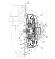
ポンプ37と、タービン38と、ステータ39とが、トルクコンバータの主構成要素を成している。ポンプがカバー11に溶接されると、トルクコンバータは、閉鎖されたチャンバになる。カバーはコンバータ連行ディスク41(フレキシブルプレート)に結合されている。さらに、このコンバータ連行ディスク41は原動機7のクランクシャフト42にねじ締結されている。カバーは、このカバーに溶接されたウェブまたはピンを使用してコンバータ連行ディスクに結合することができる。ポンプとカバーとの間の溶接結合部は原動機トルクをポンプに伝達する。したがって、このポンプは常に原動機回転数で回転させられる。ポンプの機能は、この回転運動を使用して液体を半径方向外向きでかつ軸方向でタービンに搬送することにある。したがって、ポンプとして遠心ポンプが働く。この遠心ポンプは液体を半径方向の小さな入口から半径方向の大きな出口に搬送し、したがって、液体のエネルギを増加させる。変速機クラッチとトルクコンバータクラッチとを繋ぐための圧力は、変速機に設けられた付加的なポンプによって形成される。このポンプはポンプハブによって駆動される。
The
トルクコンバータ10内には、ポンプ(時折インペラとも呼ばれる)と、タービンと、ステータ(時折リアクタとも呼ばれる)とによって、液体循環路が形成される。この液体循環路によって、車両が停止している場合に、原動機を引き続き回転させることができ、運転者によって所望される場合に、車両を再び加速させることができる。変速機変速比に類似して、トルクコンバータは原動機トルクをトルク比によって助成する。このトルク比は入力トルクに対する出力トルクの比である。トルク比は、タービンの回転数が低いかまたは零に等しい場合(ストールとも呼ばれる)に最高となる。ストール時のトルク比は、通常、1.8〜2.2の範囲内にある。これは、トルクコンバータの出力トルクが入力トルクの1.8〜2.2倍の大きさに等しいことを意味している。これに対して、出力回転数は入力回転数よりも著しく低い。なぜならば、タービンが出力側に結合されていて、入力側が原動機回転数で回転する間に回転させられないからである。
A liquid circulation path is formed in the
タービン38は、液体によってポンプ37から吸収されたエネルギを車両の駆動のために使用する。タービンハウジング22はタービンハブ19に結合されている。このタービンハブ19はタービンのトルクをスプライン結合部によって変速機の入力軸43に伝達する。この入力軸は、変速機8に設けられた歯車および軸と、アクスルディファレンシャル9とを介して車両のホイールに結合されている。液体の、タービン羽根に作用する力は、タービンによってトルクの形で出力される。軸方向のスラスト軸受け31は、液体によって構成要素に作用する軸方向の力を吸収する。出力トルクが、静止している車両の慣性を上回るために十分となるやいなや、車両が動き始める。
The
液体のエネルギがタービンによってトルクに変換された後、液体はまだ残りのエネルギを有している。半径方向の小さな出口開口44から流出した液体は、通常、ポンプの回転に抗して作用するように、ポンプ内に流入する。ステータ39は、液体を変向させるために働き、したがって、ポンプの加速に寄与し、これによって、トルク比が高められる。ステータ39はワンウェイクラッチ46によってステータシャフト45に結合されている。このステータシャフトは変速機ハウジング47に結合されていて、回転させられない。ワンウェイクラッチ46は、ステータ39が低い回転数比の場合(ポンプがタービンよりも迅速に回転させられる場合)に回転させられることを阻止する。タービン出口44からステータ39内に流入した液体はステータ羽根48によって変向させられ、これによって、液体が回転方向でポンプ37内に流入する。
After the liquid energy is converted to torque by the turbine, the liquid still has the remaining energy. Liquid that has flowed out of the small radial outlet opening 44 typically flows into the pump to act against pump rotation. The
羽根の流入角および流出角、ポンプハウジングおよびタービンハウジングの形状ならびにトルクコンバータの全直径は、トルクコンバータの出力パラメータに影響を与える。構造に対するパラメータとして、原動機が「過回転」し得ることなしに、原動機トルクを吸収するために、トルクコンバータのトルク比、効率および能力が考慮される。これは、トルクコンバータが過度に小さく、ポンプが原動機を制動することができない場合に生ぜしめられる。 The vane inflow and outflow angles, the shape of the pump and turbine housings and the overall diameter of the torque converter affect the output parameters of the torque converter. As parameters to the structure, the torque ratio, efficiency and capacity of the torque converter are taken into account to absorb the prime mover torque without the prime mover being able to “over-rotate”. This occurs when the torque converter is too small and the pump cannot brake the prime mover.
車両が静止している間、トルクコンバータが原動機を回転させることができ、原動機トルクを出力向上のために助成することによって、低い回転数状況でトルクコンバータは満足のいく形で作業する。1よりも小さい回転数状況では、トルクコンバータが100%よりも少ない効率を有している。タービンの回転数がポンプの回転数に同化されることによって、トルクコンバータのトルク比は、約1.8〜2.2の高い値から徐々に約1のトルク比に戻される。この1の回転数状況の達成時の回転数比はカップリングポイントと呼ばれる。このポイントでは、ステータ内に流入した液体がもはや変向させられる必要はなく、ステータに設けられたワンウェイクラッチが回転をポンプおよびタービンと同じ方向に許容する。ステータは液体を変向させないので、トルクコンバータから放出されたトルクが、吸収されたトルクに等しくなる。全液体循環路が1つのユニットとして回転させられる。 While the vehicle is stationary, the torque converter can rotate the prime mover, and the torque converter works satisfactorily in low speed situations by substituting the prime mover torque to improve output. In rotational speed situations less than 1, the torque converter has an efficiency of less than 100%. By assimilating the rotational speed of the turbine to the rotational speed of the pump, the torque ratio of the torque converter is gradually returned to a torque ratio of about 1 from a high value of about 1.8 to 2.2. The rotation speed ratio when the rotation speed condition of 1 is achieved is called a coupling point. At this point, the liquid flowing into the stator no longer needs to be redirected and a one-way clutch provided in the stator allows rotation in the same direction as the pump and turbine. Since the stator does not redirect the liquid, the torque released from the torque converter is equal to the absorbed torque. The entire liquid circuit is rotated as a unit.
液体における損失に基づき、トルクコンバータの最大の効率は92〜93%にある。したがって、トルクコンバータの入力側と出力側との機械的な結合のために、トルクコンバータクラッチ49が使用される。このトルクコンバータクラッチ49は効率を100%に高める。クラッチピストン金属薄板17は変速機制御装置の命令によってハイドロリック的に操作される。ピストン金属薄板17はその内径でOリング18によってタービンハブ19に対してシールされていて、その外径で、摩擦材料から成るリング51によってカバー11に対してシールされている。これらのシール部材は圧力チャンバを形成し、ピストン金属薄板17をカバーに結合する。この機械的な結合部はトルクコンバータの液体循環路を回避している。
Based on the loss in the liquid, the maximum efficiency of the torque converter is between 92 and 93%. Therefore, the
トルクコンバータクラッチ49の機械的な結合部は、著しく多くのねじり変動をパワートレーンに伝達する。このパワートレーンは基本的にばね・質量系を成しているので、原動機のねじり変動が系の共鳴振動を励起し得る。パワートレーンの共鳴振動を走行領域から除去するために、ダンパが使用される。このダンパは、原動機7および変速機8と共に直列に配置されたばね15を有しており、これによって、系の有効なばね定数ひいては共鳴周波数が減少させられる。
The mechanical coupling of the
トルクコンバータクラッチ49は一般的に4つの構成要素:ピストン金属薄板17、カバープレート12,16、ばね15およびフランジ13を有している。カバープレート12,16はトルクをピストン金属薄板17から圧縮ばね15に伝達する。カバープレートには、ばね15を軸方向に保持するために、このばねを取り囲んで突起52が形成されている。トルクは、リベット締めされた結合部を介してピストン金属薄板17からカバープレート12,16に伝達される。このカバープレート12,16はトルクを、ばねのための切欠きの縁部との接触によって圧縮ばね15に作用させることができる。両カバープレートは一緒にばねをその中心軸線の両側で支持する。ばね力は、フランジばねのための切欠きの縁部との接触によってフランジ13に伝達される。時折、フランジは回転方向にも舌片またはスリットを有している。このスリットはカバープレートの一部に係合しており、これによって、高いトルクの伝達の間、ばねの、過度に強い圧縮が阻止される。トルクはフランジ13からタービンハブ19と変速機の入力軸43とに伝達される。
The
エネルギは、必要な場合、時折ヒステリシスとも呼ばれる摩擦によって吸収することができる。このヒステリシスは減衰プレートのねじりと弛緩とによって生ぜしめられ、したがって、本来の摩擦トルクの2倍の大きさである。ヒステリシスアッセンブリは、一般的に、フランジ13と一方のカバープレート16との間のダイヤフラムばね(皿ばね)14から成っており、これによって、フランジ13が他方のカバープレート12に向かって押圧される。ダイヤフラムばね14に加えられる力の制御によって、摩擦トルクも制御することができる。一般的なヒステリシス値は10〜30Nmの範囲内にある。
Energy can be absorbed by friction, sometimes called hysteresis, if necessary. This hysteresis is caused by torsion and relaxation of the damping plate and is therefore twice as large as the original friction torque. The hysteresis assembly generally consists of a diaphragm spring (disc spring) 14 between the
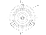
図2には、トルクコンバータ10がポンプ37とカバー41とを有していることが示してある。数多くの事例では、カバーとポンプとは低炭素鋼から成っていて、1回の打抜き加工プロセスによって形成される。カバーには、突起とガイドエレメントとが溶接されている。カバーとポンプとはフランジで溶接シームによって互いにシールされている。原動機付き車両の原動機のトルクは、突起によってカバーに伝達される。この場合、トルクは、カバーとポンプとを互いに結合する溶接シームによってポンプに伝達される。
FIG. 2 shows that the
カバーとポンプとの打抜き加工は、複数回のステップを要求する、コストおよび時間のかかるプロセスを成している。さらに、突起およびガイドエレメントを溶接するためのステップはコストおよび時間を要し、汚染に繋がり得る。最終的には、溶接シームによるポンプ37とカバー41との結合のためのプロセスが不安定となり、トルクコンバータの内部の汚染に繋がる。
The punching of the cover and pump is a costly and time consuming process that requires multiple steps. Furthermore, the steps for welding the protrusions and guide elements are costly and time consuming and can lead to contamination. Eventually, the process for coupling the
したがって、数年来、溶接シームなしに簡単に製作することができるトルクコンバータに課せられる要求がある。さらに、数年来、簡単にポンプに固定することができる一層簡単なカバーに課せられる要求がある。 Therefore, there has been a demand imposed on torque converters that can be easily manufactured without welding seams for several years. Furthermore, there has been a demand imposed on simpler covers that can be easily fixed to the pump for several years.
本発明の課題は、溶接シームなしに互いに結合されたカバーとポンプとを備えたトルクコンバータを提供することである。 It is an object of the present invention to provide a torque converter with a cover and a pump that are joined together without a weld seam.
この課題を解決するために本発明の第1のトルクコンバータでは、トルクコンバータにおいて、当該トルクコンバータが、ポンプとカバーとを有しており、ポンプまたはカバーが、さらに、ポンプの縁部またはカバーの縁部に配置された少なくとも1つのスリットを有しており、他方の部分を成すカバーまたはポンプが、さらに、該他方の部分を成すカバーまたはポンプの縁部に配置された少なくとも1つの突出部を有しており、該突出部が、カバーとポンプとを互いに結合するために、軸方向で少なくとも1つのスリットを通って突出するようになっているようにした。 In order to solve this problem, in the first torque converter of the present invention, in the torque converter, the torque converter includes a pump and a cover, and the pump or the cover further includes a pump edge or a cover. A cover or pump having at least one slit arranged at the edge and forming the other part, and further comprising at least one protrusion arranged at the edge of the cover or pump forming the other part. And the protrusion protrudes through at least one slit in the axial direction in order to connect the cover and the pump to each other.
本発明の第1のトルクコンバータの有利な構成によれば、当該トルクコンバータが、さらに、カバーとポンプとの間に配置されたシールエレメントを有している。 According to an advantageous configuration of the first torque converter according to the invention, the torque converter further comprises a sealing element arranged between the cover and the pump.
本発明の第1のトルクコンバータの有利な構成によれば、シールエレメントが、Oリングおよび平形シール部材から成るグループから選択されるようになっている。 According to an advantageous configuration of the first torque converter of the invention, the sealing element is selected from the group consisting of an O-ring and a flat sealing member.
本発明の第1のトルクコンバータの有利な構成によれば、少なくとも1つの突出部が、ポンプとカバーとを締め合わせるように半径方向に曲げ返されるようになっている。 According to an advantageous configuration of the first torque converter of the invention, at least one protrusion is bent back in the radial direction so as to clamp the pump and the cover together.
本発明の第1のトルクコンバータの有利な構成によれば、ポンプまたはカバーが、さらに、外面を有しており、半径方向の環状の突出部が、ポンプまたはカバーの縁部の近くで外面に配置されており、スリットが、半径方向の突出部に配置されている。 According to an advantageous configuration of the first torque converter of the present invention, the pump or cover further has an outer surface, and the radial annular protrusion is on the outer surface near the edge of the pump or cover. The slits are arranged on the protrusions in the radial direction.
本発明の第1のトルクコンバータの有利な構成によれば、半径方向の環状の突出部が、ポンプまたはカバーの一体の構成要素として形成されている。 According to an advantageous configuration of the first torque converter according to the invention, the radial annular projection is formed as an integral component of the pump or cover.
本発明の第1のトルクコンバータの有利な構成によれば、半径方向の環状の突出部が、ポンプまたはカバーと別個に形成されていて、ポンプまたはカバーに固く結合されている。 According to an advantageous configuration of the first torque converter of the invention, the radial annular projection is formed separately from the pump or cover and is rigidly connected to the pump or cover.
本発明の第1のトルクコンバータの有利な構成によれば、当該トルクコンバータが、さらに、支持リングを有しており、該支持リングが、少なくとも1つの突出部の近くで周面にポンプまたはカバーを取り囲んで配置されている。 According to an advantageous configuration of the first torque converter of the invention, the torque converter further comprises a support ring, the support ring being on the circumferential surface near the at least one protrusion. Is placed around.
本発明の第1のトルクコンバータの有利な構成によれば、支持リングが、少なくとも1つの突出部に接触して位置している。 According to an advantageous configuration of the first torque converter of the invention, the support ring is located in contact with at least one protrusion.
本発明の第1のトルクコンバータの有利な構成によれば、当該トルクコンバータが、さらに、L字形支持リングを有しており、該L字形支持リングが、少なくとも1つの突出部の近くで周面に、他方の部分を成すカバーまたはポンプを取り囲んで配置されている。 According to an advantageous configuration of the first torque converter of the invention, the torque converter further comprises an L-shaped support ring, the L-shaped support ring being a peripheral surface near the at least one protrusion. Is disposed around the cover or pump forming the other part.
本発明の第1のトルクコンバータの有利な構成によれば、L字形支持リングが、少なくとも1つの突出部に接触して位置している。 According to an advantageous configuration of the first torque converter of the invention, the L-shaped support ring is located in contact with at least one protrusion.
本発明の第1のトルクコンバータの有利な構成によれば、ポンプが、低炭素鋼を含有している。 According to an advantageous configuration of the first torque converter of the invention, the pump contains low carbon steel.
本発明の第1のトルクコンバータの有利な構成によれば、ポンプが、打抜き加工によって形成されるようになっている。 According to an advantageous configuration of the first torque converter of the invention, the pump is formed by stamping.
本発明の第1のトルクコンバータの有利な構成によれば、カバーが、鋳造によって形成されるようになっている。 According to an advantageous configuration of the first torque converter of the invention, the cover is formed by casting.
本発明の第1のトルクコンバータの有利な構成によれば、カバーに用いられる材料が、鋼合金、鋳鉄およびアルミニウムから成るグループから選択されるようになっている。 According to an advantageous configuration of the first torque converter of the invention, the material used for the cover is selected from the group consisting of steel alloys, cast iron and aluminum.
本発明の第1のトルクコンバータの有利な構成によれば、カバーが、打抜き加工によって形成されるようになっている。 According to an advantageous configuration of the first torque converter of the invention, the cover is formed by punching.
本発明の第1のトルクコンバータの有利な構成によれば、カバーが、さらに、カバーの一体の構成要素である少なくとも1つの突起と、カバーの一体の構成要素であるガイドエレメントとを有している。 According to an advantageous configuration of the first torque converter of the invention, the cover further comprises at least one protrusion which is an integral component of the cover and a guide element which is an integral component of the cover. Yes.
本発明の第1のトルクコンバータの有利な構成によれば、カバーが、トルクを吸収しかつ該トルクを少なくとも1つの突出部によって伝達するように配置されている。 According to an advantageous configuration of the first torque converter of the present invention, the cover is arranged to absorb the torque and transmit the torque by means of at least one protrusion.
さらに、前述した課題を解決するために本発明の第1の方法では、入力ユニットのトルクを伝達するための方法において、当該方法が、以下のステップ:すなわち、トルクコンバータのポンプまたはカバーの、縁部に配置された少なくとも1つの突出部を、それぞれ他方の部分を成すカバーまたはポンプに設けられた、縁部に配置された少なくとも1つの開口を通して案内し;カバーとポンプとを締め合わせるために、少なくとも1つの突出部を半径方向に曲げ返し;トルクをカバーから少なくとも1つの突出部を介してポンプに伝達する:を有しているようにした。 Furthermore, in order to solve the above-mentioned problems, in a first method of the present invention, in a method for transmitting torque of an input unit, the method comprises the following steps: an edge of a pump or cover of a torque converter At least one protrusion arranged in the part is guided through at least one opening located in the edge provided in the cover or pump each forming the other part; for fastening the cover and the pump, At least one protrusion bent back radially; torque is transmitted from the cover to the pump via the at least one protrusion.
さらに、前述した課題を解決するために本発明の第2の方法では、トルクコンバータをシールするための方法において、当該方法が、以下のステップ:すなわち、トルクコンバータのポンプまたはカバーの縁部に配置された少なくとも1つの突出部を、それぞれ他方の部分を成すカバーまたはポンプの縁部に配置された少なくとも1つの開口を通して案内し;シールエレメントをカバーとポンプとの間に配置し;カバーとポンプとをシールエレメントに向かって押圧するために、少なくとも1つの突出部を半径方向に曲げ返す:を有しているようにした。 Further, in order to solve the above-mentioned problems, in a second method of the present invention, in a method for sealing a torque converter, the method is arranged in the following steps: namely at the edge of the pump or cover of the torque converter At least one protrusion is guided through at least one opening arranged in the edge of the cover or pump, each of which forms the other part; a sealing element is arranged between the cover and the pump; At least one protrusion is bent back in the radial direction in order to press against the sealing element.
さらに、前述した課題を解決するために本発明の第3の方法では、トルクコンバータをバランス調整するための方法において、当該方法が、以下のステップ:すなわち、トルクコンバータのポンプまたはカバーの縁部に配置された少なくとも1つの突出部を、それぞれ他方の部分を成すカバーまたはポンプの縁部に配置されたリングに設けられた少なくとも1つの開口を通して案内し;カバーとポンプとを締め合わせるために、少なくとも1つの突出部を半径方向に曲げ返し;トルクコンバータをバランス調整するために必要となる量と同じ量の材料をリングから除去する:を有しているようにした。 Furthermore, in order to solve the above-mentioned problems, in a third method of the present invention, in a method for balancing a torque converter, the method comprises the following steps: at the pump converter or cover edge of the torque converter. Guiding at least one protrusion disposed through at least one opening provided in a ring disposed at the edge of the cover or pump each forming the other part; at least for fastening the cover and the pump One protrusion is bent back in the radial direction; the same amount of material required to balance the torque converter is removed from the ring.
さらに、前述した課題を解決するために本発明の第2のトルクコンバータでは、トルクコンバータにおいて、当該トルクコンバータが、鋳造カバーと、一体の構成要素として少なくとも1つのフランジと、一体の構成要素として少なくとも1つのガイドエレメントと、打抜き加工されたインペラと、カバーとインペラとの間に配置されたシールエレメントとを有しており、鋳造カバーが、少なくとも1つのスリットを備えており、該スリットが、カバーの縁部に配置されており、インペラが、少なくとも1つの突出部を備えており、該突出部が、インペラの周面に配置されており、少なくとも1つの突出部が、軸方向で少なくとも1つのスリットを通って突出するようになっていて、半径方向に曲げ返されるようになっており、これによって、インペラとカバーとが締め合わされるようになっており、シール部が、シールエレメントと、カバーと、インペラとの間に形成されるようになっているようにした。 Furthermore, in order to solve the above-described problems, in the second torque converter of the present invention, in the torque converter, the torque converter includes a cast cover, at least one flange as an integral component, and at least as an integral component. A guide element, a stamped impeller, and a sealing element disposed between the cover and the impeller, the cast cover having at least one slit, the slit being a cover The impeller has at least one protrusion, the protrusion is disposed on the peripheral surface of the impeller, and the at least one protrusion has at least one protrusion in the axial direction. It protrudes through the slit and is bent back in the radial direction. It is adapted to the impeller and the cover are pressed together, the seal portion, and a sealing element, a cover, and so is adapted to be formed between the impeller.
さらに、前述した課題を解決するために本発明の第3のトルクコンバータでは、トルクコンバータにおいて、当該トルクコンバータが、カバーとポンプとを有しており、カバーが、少なくとも1つのスリットを備えており、該スリットが、カバーの縁部に配置されており、ポンプが、少なくとも1つの突出部を備えており、該突出部が、ポンプの縁部に位置していて、軸方向で少なくとも1つのスリットを通って突出するようになっており、これによって、ポンプが、カバーに固定されるようになっているようにした。 Furthermore, in order to solve the above-described problem, in the third torque converter of the present invention, in the torque converter, the torque converter includes a cover and a pump, and the cover includes at least one slit. The slit is arranged at the edge of the cover and the pump is provided with at least one protrusion, the protrusion being located at the edge of the pump and at least one slit in the axial direction Through which the pump is secured to the cover.
本発明は、一般的に、トルクコンバータに関する。このトルクコンバータはポンプまたはカバーを有している。このポンプまたはカバーは、その周面に配置された少なくとも1つのスリットを備えている。それぞれ他方の部分を成すカバーまたはポンプは、その縁部に配置された少なくとも1つの突出部を有している。この突出部は軸方向で少なくとも1つのスリットを通って突出し、これによって、ポンプがカバーに結合される。幾つかの観点によれば、ポンプまたはカバーが外面と半径方向の環状の突出部とを有している。この突出部は縁部の近くで外面に配置されている。スリットは半径方向の突出部に配置されている。幾つかの観点によれば、半径方向の環状の突出部が、ポンプまたはカバーの一体の構成要素として形成されているかまたはポンプまたはカバーと別個に形成されていて、ポンプまたはカバーに固く結合されている。幾つかの観点によれば、トルクコンバータが、Oリングまたは平形シール部材の形のシールエレメントを有している。このシールエレメントはカバーとポンプとの間に配置されている。幾つかの観点によれば、少なくとも1つの突出部が半径方向に曲げ返されており、これによって、ポンプとカバーとが締め合わされる。幾つかの観点によれば、トルクコンバータが、ポンプまたはカバーの縁部に配置されたリングまたはそれぞれ他方の部分を成すカバーまたはポンプの縁部に配置されたL字形リングを有している。幾つかの観点によれば、リングまたはL字形リングが突出部に接触している。 The present invention generally relates to torque converters. This torque converter has a pump or a cover. This pump or cover is provided with at least one slit arranged on its peripheral surface. The cover or pump, each forming the other part, has at least one protrusion arranged on its edge. The protrusion protrudes axially through at least one slit, thereby coupling the pump to the cover. According to some aspects, the pump or cover has an outer surface and a radial annular protrusion. This protrusion is arranged on the outer surface near the edge. The slit is arranged in the protruding portion in the radial direction. According to some aspects, the radial annular protrusion is formed as an integral component of the pump or cover or formed separately from the pump or cover and is rigidly coupled to the pump or cover. Yes. According to some aspects, the torque converter has a sealing element in the form of an O-ring or a flat sealing member. This sealing element is arranged between the cover and the pump. According to some aspects, the at least one protrusion is bent back radially, thereby clamping the pump and the cover together. In accordance with some aspects, the torque converter has a ring located at the edge of the pump or cover or an L-shaped ring located at the edge of the cover or pump that respectively forms the other part. According to some aspects, the ring or L-shaped ring is in contact with the protrusion.
幾つかの観点によれば、ポンプが低炭素鋼から成っているかまたは1回の打抜き加工プロセスによって形成される。幾つかの観点によれば、カバーが鋳造部分として鋼合金、鋳鉄またはアルミニウムから製作される。幾つかの観点によれば、カバーが打抜き加工によって形成される。幾つかの観点によれば、カバーが、このカバーの一体の構成要素である少なくとも1つのフランジと、カバーの一体の構成要素である少なくとも1つガイドエレメントとを有している。 According to some aspects, the pump is made of low carbon steel or formed by a single stamping process. According to some aspects, the cover is made of steel alloy, cast iron or aluminum as a cast part. According to some aspects, the cover is formed by stamping. According to some aspects, the cover has at least one flange that is an integral component of the cover and at least one guide element that is an integral component of the cover.
さらに、本発明は、一般的に、入力ユニットのトルクを伝達するための方法を包括する。当該方法は、トルクコンバータのポンプまたはカバーの縁部に配置された少なくとも1つの突出部を、それぞれ他方の部分を成すカバーまたはポンプの縁部に配置された少なくとも1つの開口を通して案内し、カバーとポンプとを締め合わせるために、少なくとも1つの突出部を半径方向に曲げ返し、この少なくとも1つの突出部によってトルクをカバーからポンプに伝達する。 Furthermore, the present invention generally encompasses a method for transmitting input unit torque. The method guides at least one protrusion located at the edge of the pump or cover of the torque converter through at least one opening located at the edge of the cover or pump, respectively, forming the other part, In order to tighten the pump, at least one protrusion is bent back radially, and torque is transmitted from the cover to the pump by the at least one protrusion.
さらに、本発明は、一般的に、トルクコンバータをシールするための方法を包括する。当該方法は、トルクコンバータのポンプまたはカバーの縁部に配置された少なくとも1つの突出部を、それぞれ他方の部分を成すカバーまたはポンプの縁部に配置された少なくとも1つの開口を通して案内し、シール部材をカバーとポンプとの間に配置し、カバーとポンプとをシールエレメントに向かって押圧するために、少なくとも1つの突出部を半径方向に曲げ返す。 Furthermore, the present invention generally encompasses a method for sealing a torque converter. The method guides at least one protrusion located at the edge of the pump or cover of the torque converter through at least one opening located at the edge of the cover or pump, respectively, forming the other part, and sealing member Is placed between the cover and the pump, and at least one protrusion is bent back radially in order to press the cover and the pump towards the sealing element.
一般的に、本発明は、トルクコンバータをバランス調整するための方法を包括する。当該方法は、トルクコンバータのポンプまたはカバーの縁部に配置された少なくとも1つの突出部を、それぞれ他方の部分を成すカバーまたはポンプの縁部に配置されたリングに設けられた少なくとも1つの開口を通して案内し、カバーとポンプとを締め合わせるために、少なくとも1つの突出部を曲げ返し、トルクコンバータをバランス調整するために必要となる量と同じ量の材料をリングの外面から除去する。 In general, the present invention encompasses a method for balancing a torque converter. The method includes passing at least one protrusion located at the edge of the pump or cover of the torque converter through at least one opening provided in a ring located at the edge of the cover or pump that respectively forms the other part. To guide and tighten the cover and pump, the at least one protrusion is bent back and the same amount of material required to balance the torque converter is removed from the outer surface of the ring.
さらに、本発明は、一般的に、鋳鉄カバーを備えたトルクコンバータも包括する。鋳造カバーは、その縁部に配置された少なくとも1つのスリットと、カバーの一体の構成要素である少なくとも1つの突起およびガイドエレメントとを備えている。さらに、コンバータは、縁部に配置された少なくとも1つの突出部を備えた打抜き加工されたポンプと、カバーとポンプとの間に配置されたシールエレメントとを有している。少なくとも1つの突出部は軸方向で少なくとも1つのスリットを通って突出していて、半径方向に曲げ返されており、これによって、ポンプがカバーに締め合わされ、シールエレメントを取り囲んで、シール部がカバーとポンプとの間に形成される。 Furthermore, the present invention generally includes a torque converter with a cast iron cover. The cast cover includes at least one slit disposed at its edge and at least one protrusion and guide element that are integral components of the cover. Furthermore, the converter has a stamped pump with at least one protrusion arranged at the edge, and a sealing element arranged between the cover and the pump. The at least one protrusion protrudes axially through the at least one slit and is bent back in the radial direction so that the pump is clamped to the cover and surrounds the sealing element so that the sealing part is in contact with the cover. It is formed between the pump.
さらに、本発明は、一般的に、ポンプとカバーとを有するトルクコンバータを包括する。カバーは、その縁部に配置された少なくとも1つのスリットを有している。ポンプは、その縁部に配置された少なくとも1つの突出部を有している。この突出部は、カバーとポンプとを互いに結合するために、少なくとも1つのスリットを通って突出している。 Furthermore, the present invention generally includes a torque converter having a pump and a cover. The cover has at least one slit arranged at its edge. The pump has at least one protrusion arranged at its edge. The protrusion protrudes through at least one slit to couple the cover and the pump together.
本発明の前述した課題ならびに別の課題および利点は、本発明の有利な実施例の以下の説明と、添付した図面および特許請求の範囲とから明らかである。 The foregoing and other objects and advantages of the invention will be apparent from the following description of an advantageous embodiment of the invention and from the accompanying drawings and claims.
以下に、本発明を実施するための最良の形態を図面につき詳しく説明する。 In the following, the best mode for carrying out the present invention will be described in detail with reference to the drawings.
念のために最初から明らかにしておくと、同じ符号は、種々異なる図面において、本発明の同一のまたは機能的に類似の構造エレメントを示している。本発明を、現在有利であると見なされる観点に関して説明するにもかかわらず、念のために明らかにしておくと、本発明は、記載した観点に限定されていない。 To be clear from the beginning, the same reference numbers indicate the same or functionally similar structural elements of the present invention in different drawings. Although the present invention has been described with respect to aspects that are presently considered to be advantageous, for the sake of clarity, the present invention is not limited to the described aspects.
さらに、明らかであるように、本発明は、記載した特定の方法、材料および変更に限定されておらず、この限りおいて、当然ながら、変えられてよい。さらに、明らかであるように、ここで使用される概念は特定の観点の説明のためにしか役立たず、本発明の、従属請求項によってしか限定されない構成範囲の限定として解されるべきものではない。 Further, as will be apparent, the invention is not limited to the specific methods, materials and modifications described, but may, of course, be varied. Furthermore, as will be clear, the concepts used here serve only to explain certain aspects and should not be construed as limiting the scope of the invention, which is limited only by the dependent claims. .
その他の点で規定されない限り、ここで使用される全ての技術的なかつ科学的な概念は、本発明が関係する当業者に慣用である意味と同じ意味を有している。本発明の実施またはテストのために、ここで説明する方法、装置または材料に類似であるかまたは等価である任意の方法、装置または材料を使用することができるにもかかわらず、以下に有利な方法、装置および材料を説明する。 Unless defined otherwise, all technical and scientific concepts used herein have the same meaning as commonly used by one of ordinary skill in the art to which this invention pertains. Although any method, apparatus or material similar or equivalent to the methods, apparatus or materials described herein may be used for the practice or testing of the present invention, the following are advantageous. The method, apparatus and materials are described.
図7aは、円筒状の座標系80の斜視図である。この座標系80は、本出願に使用される空間的な概念を成している。本発明を円筒状の座標系80に相俟って少なくとも部分的に説明する。この系80は長手方向軸線81を有している。この長手方向軸線81は、以下の方向概念および空間的な概念に対する基準として役立つ。付加語「軸方向」、「半径方向」および「周〜」は、軸線81、(この軸線81に対して垂直である)半径82もしくは周83に対して平行な方向付けに関する。付加語「軸方向」、「半径方向」および「周〜」は、相応の平面に対して平行な方向付けにも関する。それぞれ異なる平面の位置を説明するために、対象物84,85,86が役立つ。対象物84の面87は軸方向の平面を形成している。すなわち、軸線が面に沿った線を形成している。対象物85の面88は半径方向の平面を形成している。すなわち、半径82が面に沿った線を形成している。対象物86の面89は周面を形成している。すなわち、周83が面に沿った線を形成している。別の例によれば、軸方向の運動または位置が軸線81に対して平行に延びており、半径方向の運動または位置が半径82に対して平行に延びており、周方向運動または周方向位置が周83に対して平行に延びている。回転は軸線を中心として行われる。
FIG. 7 a is a perspective view of a cylindrical coordinate
付加語「軸方向」、「半径方向」および「周〜」は、軸線81、半径82もしくは周83に対して平行な方向付けに関する。付加語「軸方向」、「半径方向」および「周〜」は、相応の平面に対して平行な方向付けにも関する。
The additional words “axial direction”, “radial direction” and “circumferential” relate to an orientation parallel to the
図7bは、本出願に使用される空間的な概念を成す図7aの円筒状の座標系80における対象物90の斜視図である。この円筒状の対象物90は、円筒状の座標系における円筒状の対象物の代わりを成しており、決して本発明の限定として解されるべきものではない。対象物90は、軸方向の面91と、半径方向の面92と、周面93とを有している。面91は軸方向の平面の一部であり、面92は半径方向の平面の一部であり、面93は周平面の一部である。
FIG. 7b is a perspective view of the
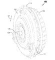
図8は、本発明によるトルクコンバータ100の斜視的な正面図である。
FIG. 8 is a perspective front view of the
図9は、図8に示したカバー102の斜視的な背面図である。
FIG. 9 is a perspective rear view of the
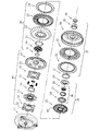
図10は、図8に示したポンプもしくはインペラ104の斜視的な正面図である。以下の説明は、図8〜図10に相俟って見ることができる。カバー102は、カバーの縁部108に配置されたスリット106を有している。このスリットは半径方向の環状の突出部またはリング110に形成されている。このリング110は縁部108の近くでカバーの外面111に配置されている。幾つかの観点によれば、リングは突出部112の形で縁部に対して軸方向にずらされている。幾つかの観点(図示せず)によれば、リングは半径方向で縁部に位置決めされている。ポンプ104は少なくとも1つの突出部または舌片114を有している。この舌片114はポンプの縁部116に配置されている。突出部114は、ポンプをカバーに固定するために、軸方向でスリットを通って突出している。明らかしておくと、本発明によるトルクコンバータは、スリットおよび突出部の図示の個数、サイズ、形状または配置形式に限定されておらず、スリットおよび突出部の別の個数、サイズ、形状および配置形式が、本発明の精神および構成範囲に含まれている。
10 is a perspective front view of the pump or
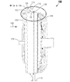
図11は、図8に示したトルクコンバータ100の横断面図である。このトルクコンバータ100の内側の構成要素は、図面を明瞭にするために取り除かれている。以下の説明は、図8〜図11に相俟って見ることができる。トルクコンバータ100は、カバーとポンプとの間に配置されたシールエレメント118を有している。幾つかの観点によれば、このシールエレメント118は、リング110と、突出部112と、舌片114とによって規定された容積内に配置されている。特にカバーには、切欠きまたは凹部120が形成されている。シールエレメントに対して、Oリングまたは平形シール部材を含めた技術的に知られている任意の手段を使用することができるものの、これに限定されていない。シールエレメント118は液体密なシール部をカバーとポンプとの間に形成する。
FIG. 11 is a cross-sectional view of
カバーをポンプに固定するためには、突出部114が半径方向に曲げ返される。第1の組付けステップでは、突出部が、たとえば軸方向でスリットを通って突出し、図面に破線122によって示してある。その後、舌片が方向124に曲げ返され、これによって、図面に示したアッセンブリが形成される。舌片の曲返しにより、この舌片によって、軸方向の圧力がリング110の方向126に加えられ、これによって、カバーとポンプとが引き合わされ、カバーとポンプとの間のシールエレメント118が圧縮される。したがって、溶接法を使用し、これに相俟って、上述した難点を甘受することなしに、液体密なシール部が形成される。
In order to secure the cover to the pump, the
カバー102は、たとえばフランジ128によって、車両(図示せず)に設けられた原動機(図示せず)にフランジ結合することができるように提供されている。トルクは原動機からカバーに伝達される。このカバーはトルクをさらにリング110を介してポンプ104に伝達する。すなわち、縁部に配置されたスリットの縁部が、縁部に配置された舌片の縁部に接触し、トルクの最大の部分を伝達する。たとえば、縁部132は、トルクをカバーの方向130に伝達するために、突出部の縁部134に接触する。したがって、カバーとポンプとの間に、溶接法を使用し、これに相俟って、上述した難点を甘受することなしに、トルクのための伝達路が形成される。
The
幾つかの観点によれば、フランジ128とガイドエレメント136とがカバーの一体の構成要素である。これによって、フランジとガイドエレメントとを形成しかつフランジとガイドエレメントとをカバーに結合するための別個の製造ステップが有利に回避される。幾つかの観点(図示せず)によれば、フランジとガイドエレメントとがカバーと別個に形成され、このカバーに固く結合される。幾つかの観点によれば、フランジまたはガイドエレメントが打抜き加工によって形成される。幾つかの観点によれば、カバーが打抜き加工によって形成される。幾つかの観点によれば、カバーが鋳造によって形成され、鋼合金、鋳鉄およびアルミニウムを含めた技術的に知られている任意の鋳造可能な材料から製作されるものの、これに限定されていない。鋳造カバーでは、フランジおよび/またはガイドエレメントをカバーに一体鋳造することができる。幾つかの観点によれば、たとえば突出部114の曲返しを可能にするために、ポンプが低炭素鋼から形成される。幾つかの観点によれば、ポンプが打抜き加工によって形成される。
According to some aspects, the
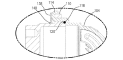
図12aは、付加的な支持リング138を備えた、図11に示した部分12aを示す図である。
FIG. 12 a shows the
図12bは、図12aに示した支持リング138の斜視図である。以下の説明は、図8〜図12bに相俟って見ることができる。幾つかの観点によれば、コンバータ100の強度を高めるために、支持リングまたは補強リング138が使用される。たとえば、このリング138はリング110および突出部の近くで縁部にカバーを取り囲んで配置されていて、このカバーに結合されている。幾つかの観点によれば、リング138は突出部114に接触している。念のために明らかにしておくと、リング138は、規定されたサイズ、形状または配置形式に限定されていない。リング138は、技術的に知られている任意の手段によってカバー102に、たとえば溶接シーム140によって固定することができる。
12b is a perspective view of the
図13aは、付加的なL字形支持リング142を備えた、図8に示した部分13aを示す図である。
FIG. 13 a shows the
図13bは、図13aに示した支持リング142の斜視図である。以下の説明は、図8〜図13bに相俟って見ることができる。幾つかの観点によれば、支持リングまたは補強リング142は、コンバータ100の強度を高めるために働く。たとえばリング142はリング110および突出部114の近くで縁部にポンプを取り囲んで配置されている。幾つかの観点によれば、リング142はリング110と突出部とに接触している。念のために明らかにしておくと、リング142は、規定されたサイズ、形状または配置形式に限定されていない。リング142は、技術的に知られている任意の手段によってポンプ104に、たとえば溶接シーム144によって固定することができる。
FIG. 13b is a perspective view of the
幾つかの観点(図示せず)によれば、スリットおよび突出の配置形式が図面に対して逆転されている。たとえばカバーが突出部を有している。この突出部はカバーの縁部に配置されている。ポンプはスリットを有している。このスリットはポンプの縁部に配置されている。一般的に、図8〜図13aの説明は、逆転された配置形式に対して使用することができる。 According to some aspects (not shown), the arrangement of the slits and protrusions is reversed with respect to the drawing. For example, the cover has a protrusion. This protrusion is arranged at the edge of the cover. The pump has a slit. This slit is located at the edge of the pump. In general, the description of FIGS. 8-13a can be used for reversed arrangement types.
幾つかの観点(図示せず)によれば、トルクコンバータ100がリング110からの材料の除去によってバランス調整される。この材料は、穿孔、フライス削り、研削、旋削および切断を含めた技術的に知られている任意の手段を使用して除去することができるものの、これに限定されていない。たとえば、材料はトルクコンバータの重い方の側でリングから除去されてよい。重い方の側は、トルクコンバータの、より大きな重量を有していて、アンバランスを生ぜしめる部分である。
According to some aspects (not shown), the
したがって、当業者が、本発明の精神および構成範囲に含まれている本発明の変更および変化を提案することができるにもかかわらず、本発明の課題が有効に解決されることを認めることができる。さらに、上述した説明が、本発明を明瞭にするためにしか役立たず、限定として解されるべきものではないことが明らかである。したがって、本発明の精神および構成範囲から逸脱することなしに、本発明の別の構成が可能となる。 Accordingly, those skilled in the art will recognize that the subject matter of the present invention can be effectively solved, even though modifications and variations of the present invention can be proposed within the spirit and scope of the present invention. it can. Furthermore, it is clear that the above description serves only to clarify the invention and should not be construed as limiting. Accordingly, other configurations of the present invention are possible without departing from the spirit and scope of the present invention.
7 原動機、 8 変速機、 9 ディファレンシャル/アクスルアッセンブリ、 10 トルクコンバータ、 11 カバー、 12 カバープレート、 13 フランジ、 14 ダイヤフラムばね、 15 ばね、 16 カバープレート、 17 クラッチピストン金属薄板、 18 Oリング、 19 タービンハブ、 22 タービンハウジング、 31 スラスト軸受け、 37 ポンプ、 38 タービン、 39 ステータ、 41 コンバータ連行ディスク、 42 クランクシャフト、 43 入力軸、 44 出口開口、 45 ステータシャフト、 46 ワンウェイクラッチ、 47 変速機ハウジング、 48 ステータ羽根、 49 トルクコンバータクラッチ、 51 リング、 52 突起、 80 座標系、 81 長手方向軸線、 82 半径、 83 周、 84 対象物、 85 対象物、 86 対象物、 87 面、 88 面、 89 面、 90 対象物、 91 面、 92 面、 93 周面、 100 トルクコンバータ、 102 カバー、 104 ポンプ、 106 スリット、 108 縁部、 110 リング、 111 外面、 112 突出部、 114 舌片、 116 縁部、 118 シールエレメント、 120 凹部、 122 破線、 124 方向、 126 方向、 128 フランジ、 130 方向、 132 縁部、 134 縁部、 136 ガイドエレメント、 138 支持リング、 140 溶接シーム、 142 L字形支持リング、 144 溶接シーム
7 Motor, 8 Transmission, 9 Differential / Axle Assembly, 10 Torque Converter, 11 Cover, 12 Cover Plate, 13 Flange, 14 Diaphragm Spring, 15 Spring, 16 Cover Plate, 17 Clutch Piston Metal Thin Plate, 18 O Ring, 19 Turbine Hub, 22 Turbine housing, 31 Thrust bearing, 37 Pump, 38 Turbine, 39 Stator, 41 Converter entrainment disk, 42 Crankshaft, 43 Input shaft, 44 Outlet opening, 45 Stator shaft, 46 One-way clutch, 47 Transmission housing, 48 Stator blade, 49 Torque converter clutch, 51 Ring, 52 Protrusion, 80 Coordinate system, 81 Longitudinal axis, 82
Claims (23)
トルクコンバータのポンプまたはカバーの、縁部に配置された少なくとも1つの突出部を、それぞれ他方の部分を成すカバーまたはポンプに設けられた、縁部に配置された少なくとも1つの開口を通して案内し;
カバーとポンプとを締め合わせるために、少なくとも1つの突出部を半径方向に曲げ返し;
トルクをカバーから少なくとも1つの突出部を介してポンプに伝達する:
を有していることを特徴とする、入力ユニットのトルクを伝達するための方法。 In a method for transmitting input unit torque, the method comprises the following steps:
Guiding at least one protrusion located on the edge of the pump or cover of the torque converter through at least one opening located on the edge provided in the cover or pump forming the other part, respectively;
Bending back at least one protrusion radially to tighten the cover and pump;
Torque is transmitted from the cover to the pump via at least one protrusion:
A method for transmitting torque of an input unit.
トルクコンバータのポンプまたはカバーの縁部に配置された少なくとも1つの突出部を、それぞれ他方の部分を成すカバーまたはポンプの縁部に配置された少なくとも1つの開口を通して案内し;
シールエレメントをカバーとポンプとの間に配置し;
カバーとポンプとをシールエレメントに向かって押圧するために、少なくとも1つの突出部を半径方向に曲げ返す:
を有していることを特徴とする、トルクコンバータをシールするための方法。 In a method for sealing a torque converter, the method comprises the following steps:
Guiding at least one protrusion located at the edge of the pump or cover of the torque converter through at least one opening located at the edge of the cover or pump, respectively, forming the other part;
Placing a sealing element between the cover and the pump;
In order to press the cover and the pump towards the sealing element, at least one protrusion is bent back radially:
A method for sealing a torque converter, comprising:
トルクコンバータのポンプまたはカバーの縁部に配置された少なくとも1つの突出部を、それぞれ他方の部分を成すカバーまたはポンプの縁部に配置されたリングに設けられた少なくとも1つの開口を通して案内し;
カバーとポンプとを締め合わせるために、少なくとも1つの突出部を半径方向に曲げ返し;
トルクコンバータをバランス調整するために必要となる量と同じ量の材料をリングから除去する:
を有していることを特徴とする、トルクコンバータをバランス調整するための方法。 In a method for balancing a torque converter, the method comprises the following steps:
Guiding at least one protrusion located at the edge of the pump or cover of the torque converter through at least one opening provided in a ring located at the edge of the cover or pump, respectively, forming the other part;
Bending back at least one protrusion radially to tighten the cover and pump;
Remove the same amount of material from the ring that is needed to balance the torque converter:
A method for balancing a torque converter, comprising:
Applications Claiming Priority (1)
| Application Number | Priority Date | Filing Date | Title |
|---|---|---|---|
| US84218306P | 2006-09-01 | 2006-09-01 |
Publications (2)
| Publication Number | Publication Date |
|---|---|
| JP2008057783A true JP2008057783A (en) | 2008-03-13 |
| JP2008057783A5 JP2008057783A5 (en) | 2010-10-14 |
Family
ID=38989775
Family Applications (1)
| Application Number | Title | Priority Date | Filing Date |
|---|---|---|---|
| JP2007223591A Pending JP2008057783A (en) | 2006-09-01 | 2007-08-30 | Joint tongue for torque converter |
Country Status (3)
| Country | Link |
|---|---|
| US (1) | US8393863B2 (en) |
| JP (1) | JP2008057783A (en) |
| DE (1) | DE102007036058A1 (en) |
Cited By (2)
| Publication number | Priority date | Publication date | Assignee | Title |
|---|---|---|---|---|
| KR101339388B1 (en) | 2012-07-06 | 2013-12-09 | 한국파워트레인 주식회사 | Torque convertor for vehicle and method for manufacturing the same |
| KR101582337B1 (en) * | 2015-07-31 | 2016-01-05 | 송명식 | A repair methode of torque converter |
Families Citing this family (2)
| Publication number | Priority date | Publication date | Assignee | Title |
|---|---|---|---|---|
| US20120193182A1 (en) * | 2011-01-31 | 2012-08-02 | Schaeffler Technologies AG & Co. KG | Stator tabs for staking |
| US9982748B2 (en) | 2012-12-12 | 2018-05-29 | Magna International | Flexplates and method for capacitor discharge welding of flexplates |
Citations (3)
| Publication number | Priority date | Publication date | Assignee | Title |
|---|---|---|---|---|
| JPS5986460U (en) * | 1982-12-02 | 1984-06-11 | 株式会社岡村製作所 | Coupling device for cover and pump in fluid torque converter, etc. |
| JPH0728257U (en) * | 1993-10-28 | 1995-05-23 | 株式会社大金製作所 | Torque converter |
| JP2002061733A (en) * | 2000-08-24 | 2002-02-28 | Exedy Corp | Method for joining impeller and front cover of torque converter and torque converter |
Family Cites Families (18)
| Publication number | Priority date | Publication date | Assignee | Title |
|---|---|---|---|---|
| US913685A (en) * | 1908-12-15 | 1909-03-02 | David C Boyd | Culvert. |
| US2505820A (en) * | 1945-02-28 | 1950-05-02 | Borg Warner | Means for assembling and retaining radially disposed vanes |
| US2917001A (en) * | 1951-06-16 | 1959-12-15 | Borg Warner | Hydrodynamic coupling |
| US2748715A (en) * | 1952-12-20 | 1956-06-05 | Borg Warner | Hydrodynamic coupling |
| US2784675A (en) * | 1952-12-22 | 1957-03-12 | Borg Warner | Hydrodynamic coupling |
| US3138107A (en) * | 1961-11-20 | 1964-06-23 | Borg Warner | Hydrodynamic coupling devices |
| DE2346356A1 (en) * | 1973-09-14 | 1975-03-27 | Daimler Benz Ag | PUMP WHEEL FOR A HYDRODYNAMIC UNIT |
| WO1988002080A1 (en) * | 1986-09-12 | 1988-03-24 | Kabushiki Kaisha Daikin Seisakusho | Outer wall structure for hydraulic power transmissions |
| JPH05126228A (en) * | 1991-11-06 | 1993-05-21 | Nissan Motor Co Ltd | Coreless torque converter |
| DE69314550T2 (en) * | 1992-07-03 | 1998-03-26 | Toyota Motor Co Ltd | Hydraulic torque transmission unit with lock-up clutch |
| US5333500A (en) * | 1993-02-26 | 1994-08-02 | General Motors Corporation | Method of balancing a torque converter assembly |
| DE19755168B9 (en) | 1997-12-11 | 2009-07-30 | Zf Sachs Ag | Method for connecting at least two components of a torque converter |
| US6082446A (en) * | 1998-04-20 | 2000-07-04 | Ahaus Tool And Engineering, Inc. | Sealing method and apparatus for a heat exchanger |
| JP2004068832A (en) * | 2002-08-01 | 2004-03-04 | Koyo Seiko Co Ltd | One-way clutch |
| US7032729B2 (en) * | 2002-12-10 | 2006-04-25 | Ronjo Co. | Torque converter |
| JP4180954B2 (en) * | 2003-04-03 | 2008-11-12 | Nskワーナー株式会社 | One-way clutch device |
| EP1920165A1 (en) * | 2005-08-25 | 2008-05-14 | LuK Lamellen und Kupplungsbau Beteiligungs KG | Improved keyway connection |
| WO2007110024A2 (en) * | 2006-03-24 | 2007-10-04 | Luk Lamellen Und Kupplungsbau Beteiligungs Kg | Flanged or welded connection for a housing and a pump housing in a torque converter |
-
2007
- 2007-08-01 DE DE102007036058A patent/DE102007036058A1/en not_active Ceased
- 2007-08-30 JP JP2007223591A patent/JP2008057783A/en active Pending
- 2007-08-30 US US11/897,496 patent/US8393863B2/en not_active Expired - Fee Related
Patent Citations (3)
| Publication number | Priority date | Publication date | Assignee | Title |
|---|---|---|---|---|
| JPS5986460U (en) * | 1982-12-02 | 1984-06-11 | 株式会社岡村製作所 | Coupling device for cover and pump in fluid torque converter, etc. |
| JPH0728257U (en) * | 1993-10-28 | 1995-05-23 | 株式会社大金製作所 | Torque converter |
| JP2002061733A (en) * | 2000-08-24 | 2002-02-28 | Exedy Corp | Method for joining impeller and front cover of torque converter and torque converter |
Cited By (2)
| Publication number | Priority date | Publication date | Assignee | Title |
|---|---|---|---|---|
| KR101339388B1 (en) | 2012-07-06 | 2013-12-09 | 한국파워트레인 주식회사 | Torque convertor for vehicle and method for manufacturing the same |
| KR101582337B1 (en) * | 2015-07-31 | 2016-01-05 | 송명식 | A repair methode of torque converter |
Also Published As
| Publication number | Publication date |
|---|---|
| US8393863B2 (en) | 2013-03-12 |
| DE102007036058A1 (en) | 2008-03-06 |
| US20080053773A1 (en) | 2008-03-06 |
Similar Documents
| Publication | Publication Date | Title |
|---|---|---|
| JP5455328B2 (en) | Hydrodynamic coupling device for hybrid vehicles | |
| US7794358B2 (en) | Torque converter with fixed stator and method of controlling rotation of a turbine and pump in a torque converter | |
| US8096885B2 (en) | Method and apparatus for lash prevention using coil springs | |
| JP5527943B2 (en) | Torque converter | |
| US8403118B2 (en) | Three-pass turbine damper | |
| US20080149441A1 (en) | Multi function torque converter with lever spring and method for controlling hydraulic pressure and flow | |
| US8016091B2 (en) | Solid stop leaf spring | |
| JP5546101B2 (en) | One-way clutch with wedge | |
| JP2009019772A (en) | Two pass multi-function torque converter | |
| US20080277227A1 (en) | Torque converter with anti-rattle and cooling flow arrangement | |
| US20070253823A1 (en) | Turbine blade tab attachment means for a torque converter dampening spring retainer and a method of manufacturing said attachment means | |
| US7918645B2 (en) | Torque converter with brazed turbine | |
| WO2010038548A1 (en) | Fluid coupling and starting device | |
| JP2008057783A (en) | Joint tongue for torque converter | |
| US7958724B2 (en) | Torque converter blade | |
| US6827187B2 (en) | Hydrodynamic coupling device | |
| JP2008281199A (en) | Three-pass torque converter with sealed piston and forced cooling flow | |
| JP3915566B2 (en) | Torque converter | |
| JP5272239B2 (en) | Torque converter with fixed stator and method for controlling turbine and pump rotation in torque converter | |
| US20070284206A1 (en) | Pilot plate torque transmitting assembly for a torque converter | |
| JP6196811B2 (en) | Lock-up device | |
| US7770705B2 (en) | Forged piston plate drive lugs | |
| JPH11141617A (en) | Damper device | |
| JP2007051752A (en) | Fluid type torque transmission device | |
| JP5202229B2 (en) | Lock-up clutch of fluid coupling device |
Legal Events
| Date | Code | Title | Description |
|---|---|---|---|
| A521 | Written amendment |
Free format text: JAPANESE INTERMEDIATE CODE: A523 Effective date: 20100830 |
|
| A621 | Written request for application examination |
Free format text: JAPANESE INTERMEDIATE CODE: A621 Effective date: 20100830 |
|
| RD04 | Notification of resignation of power of attorney |
Free format text: JAPANESE INTERMEDIATE CODE: A7424 Effective date: 20101227 |
|
| RD04 | Notification of resignation of power of attorney |
Free format text: JAPANESE INTERMEDIATE CODE: A7424 Effective date: 20101228 |
|
| A131 | Notification of reasons for refusal |
Free format text: JAPANESE INTERMEDIATE CODE: A131 Effective date: 20120822 |
|
| A521 | Written amendment |
Free format text: JAPANESE INTERMEDIATE CODE: A523 Effective date: 20121121 |
|
| A02 | Decision of refusal |
Free format text: JAPANESE INTERMEDIATE CODE: A02 Effective date: 20130327 |
|
| RD13 | Notification of appointment of power of sub attorney |
Free format text: JAPANESE INTERMEDIATE CODE: A7433 Effective date: 20130422 |
|
| A521 | Written amendment |
Free format text: JAPANESE INTERMEDIATE CODE: A821 Effective date: 20130422 |