JP2008047047A - Input device, method and program and storage medium - Google Patents
Input device, method and program and storage medium Download PDFInfo
- Publication number
- JP2008047047A JP2008047047A JP2006224355A JP2006224355A JP2008047047A JP 2008047047 A JP2008047047 A JP 2008047047A JP 2006224355 A JP2006224355 A JP 2006224355A JP 2006224355 A JP2006224355 A JP 2006224355A JP 2008047047 A JP2008047047 A JP 2008047047A
- Authority
- JP
- Japan
- Prior art keywords
- coordinate
- dimensional
- input
- coordinates
- output
- Prior art date
- Legal status (The legal status is an assumption and is not a legal conclusion. Google has not performed a legal analysis and makes no representation as to the accuracy of the status listed.)
- Pending
Links
Images


Abstract
Description
本発明は、コンピュータ等の画面に表示されている表示内容に対して指示入力を可能とするいわゆるマウス等の入力装置及び方法、並びにプログラム及び記憶媒体に関する。特に、2次元と3次元の表示内容が混在している表示画面に対して2次元入力と3次元入力の両方が可能な入力装置及び方法、並びにプログラム及び記憶媒体に関する。 The present invention relates to a so-called mouse and other input device and method, a program, and a storage medium that enable instruction input to display contents displayed on a screen of a computer or the like. In particular, the present invention relates to an input device and method capable of performing both two-dimensional input and three-dimensional input on a display screen in which two-dimensional and three-dimensional display contents are mixed, a program, and a storage medium.
近年のコンピュータの処理能力の向上は目覚しく、容易に様々な3次元処理をこなせるところまできつつある。業務用途では、例えば、CAD等で3次元の図形を一般的な能力レベルのコンピュータで処理することが可能である。また、個人的な用途においても、3次元オブジェクトを表示させる場面が多くなってきている。更に、今後の情報技術の展開においては、オペレーティングシステムレベルでの3次元のデスクトップ画面を構成する動きがある。 Recent improvements in computer processing power are remarkable, and various three-dimensional processes can be easily performed. In business use, for example, a three-dimensional figure can be processed by a computer having a general ability level by CAD or the like. Also, for personal use, there are many scenes where a three-dimensional object is displayed. Furthermore, in the future development of information technology, there is a movement to construct a three-dimensional desktop screen at the operating system level.
このようなコンピュータを取り巻く環境ではあるが、現在は2次元の画像に対してマウスやペンにおける2次元の座標入力による操作が圧倒的に多い。ただし、今後は上述の通り、3次元の画像情報が増えてきて、2次元画像と3次元画像が混在した画面が増え、それに対して指示入力する機会も増えていくものと考えられる。 Although it is an environment surrounding such a computer, at present, there are overwhelmingly many operations by two-dimensional coordinate input with a mouse or a pen for a two-dimensional image. However, in the future, as described above, three-dimensional image information will increase, and the number of screens in which two-dimensional images and three-dimensional images are mixed will increase.
現在、2次元座標の入力が可能な入力装置のほとんどはマウスあるいはペンである。マウスでの入力にはLEDやレーザーを用いた光学式を利用したものが主流になっている。また、3次元座標の入力が可能な入力装置は、用途がまだ限定的であるため一般的ではないが、様々な方式のものが提案されている。 Currently, most input devices that can input two-dimensional coordinates are a mouse or a pen. For the input with a mouse, the one using an optical system using an LED or a laser is the mainstream. In addition, input devices capable of inputting three-dimensional coordinates are not general because their uses are still limited, but various types of input devices have been proposed.
例えば、磁気センサ、超音波センサ、イメージセンサを用いたものがある。 For example, there are magnetic sensors, ultrasonic sensors, and image sensors.
磁気センサを用いたものは、磁束の変化によってコイルに起電力が生じるという原理を利用している。ただし、磁気センサは、水平に保持するのが原則で、傾けて使用すると方位に誤差が生じる。これは、地磁気の垂直成分を拾うためであり、傾斜の自動補正は、3軸の磁気センサと水平を検知する傾斜センサを組合せることで可能となる。 A device using a magnetic sensor utilizes the principle that an electromotive force is generated in a coil due to a change in magnetic flux. However, in principle, the magnetic sensor is held horizontally, and if it is used at an angle, an error occurs in the direction. This is because the vertical component of geomagnetism is picked up, and automatic tilt correction is possible by combining a triaxial magnetic sensor and a tilt sensor that detects horizontal.
超音波センサを用いたものは、一般的に磁気センサよりも安価に構成できる。3次元位置を計測する原理は、1つの超音波発振器に対して3つの受信器を配置し、各々に超音波が到達するまでの時間遅れを計測する。そして、三角測量の原理により、受信器と発振器の位置関係を定めることができる。この原理であれば、更に複数の受信器を構成することにより、姿勢(角度)の測定も可能である。ただし、空気中の音速変化(雑音や反射などによる)が誤差要因となるため、高精度の検出は困難である。 In general, an ultrasonic sensor can be configured at a lower cost than a magnetic sensor. The principle of measuring the three-dimensional position is that three receivers are arranged for one ultrasonic oscillator, and the time delay until the ultrasonic wave reaches each is measured. The positional relationship between the receiver and the oscillator can be determined by the principle of triangulation. With this principle, posture (angle) can be measured by configuring a plurality of receivers. However, since a change in sound velocity in the air (due to noise, reflection, etc.) becomes an error factor, it is difficult to detect with high accuracy.
イメージセンサを用いたものは、カメラ(2台以上)から取り込んだ動画像について、その画像内の特徴点(例えばLED発光点など) の3次元位置をリアルタイムで計測するものである。 The image sensor is used to measure in real time the three-dimensional position of feature points (for example, LED emission points) in an image captured from a camera (two or more).
更に、複数の技術を組合わせて3次元の入力を高精度に可能とするもの(例えば、磁気センサと加速度センサの組合わせ、画像とジャイロの組合わせ等)がある。 Further, there is a technique (for example, a combination of a magnetic sensor and an acceleration sensor, a combination of an image and a gyro, etc.) that enables a three-dimensional input with high accuracy by combining a plurality of techniques.
また、2次元のマウス(XY座標を出力可能)にZ軸の座標や回転方向(自由度方向)の情報を出力することができる座標入力装置が提案されている。例えば、特許文献1には、電磁誘導作用を利用した位置検出装置と組合わせて用い、複数の操作子を設けて3次元空間上のオブジェクトの移動と回転の動きに対応した6自由度の情報を出力する指示器の提案がなされている。
In addition, a coordinate input device has been proposed that can output information on the Z-axis coordinates and the rotation direction (direction of freedom) to a two-dimensional mouse (which can output XY coordinates). For example,
また、2次元のマウスに付加価値を付ける提案として、マウスが持ち上げられた場合にマウスのボタンスイッチが別の機能となる提案がなされている(特許文献2)。 In addition, as a proposal for adding value to a two-dimensional mouse, there is a proposal in which a mouse button switch has another function when the mouse is lifted (Patent Document 2).
また、光を用いた座標入力装置であり、座標を出力する以外に操作者に別の情報を与えることが可能なマウスが提案されている。このマウスは、発光手段が設けられたポインティングデバイスを動かすことにより、発光手段の位置や動きに対応させた触覚情報を操作者に与えることができるようになっている(特許文献3)。
実空間において2次元で構成される表示装置の画面に対しては、2次元座標の入力装置であるマウスでの入力が一般的であり、手を置いたまま操作する使用形態は長時間使用する場合でも疲労度が少なく、使い勝手がよい。そのため、この使い方は、基本的には今後も変わらないと考えられる。 For a screen of a display device configured in two dimensions in a real space, input with a mouse, which is an input device for two-dimensional coordinates, is common, and a usage mode in which a user operates with a hand used for a long time. Even in this case, the degree of fatigue is low and it is easy to use. Therefore, this usage will not change in the future.
しかしながら、対象物の拡大・縮小や回転等を3次元の空間で行うことが可能な3次元オブジェクトを操作する場合には、2次元の座標を出力するマウスでは、操作が複雑になる。具体的には、拡大・縮小、回転などのコマンドに対して、画面上のボタンやスライダーを操作し、あるいはマウスボタンを押しながらマウスを移動する等の操作をしなければならない。この操作は、操作者にとっては、直感的ではないため操作性の観点で決して優れているといえるものではなかった。 However, when operating a three-dimensional object capable of enlarging / reducing or rotating an object in a three-dimensional space, the operation is complicated with a mouse that outputs two-dimensional coordinates. Specifically, for commands such as enlargement / reduction, rotation, etc., operations such as operating buttons and sliders on the screen or moving the mouse while pressing the mouse button must be performed. Since this operation is not intuitive for the operator, it cannot be said that it is excellent in terms of operability.
また、3次元オブジェクトを操作可能な3次元座標入力装置に関しては、3次元の操作には優れているが、2次元画像情報に対する入力に対しては決して操作性がよいとはいえない。2次元の画像を操作するためには2次元の座標のみで操作が可能であるにもかかわらず、3次元座標入力装置では、3次元の座標が出力されているために操作者が意図しない動きが検出されることがあるため、思うように操作ができないという課題があった。 A three-dimensional coordinate input device capable of manipulating a three-dimensional object is excellent in three-dimensional operation, but cannot be said to have good operability for inputting two-dimensional image information. Although a two-dimensional image can be manipulated using only two-dimensional coordinates, the three-dimensional coordinate input device outputs a three-dimensional coordinate, which is not intended by the operator. May be detected, and there is a problem that the operation cannot be performed as expected.
本発明の目的は、2次元画像情報と3次元画像情報とが混在する表示画面に対しても、操作性良く入力が可能な入力装置及び方法、並びにプログラム及び記憶媒体を提供することにある。 An object of the present invention is to provide an input device and method, a program, and a storage medium that can input with good operability even on a display screen in which two-dimensional image information and three-dimensional image information are mixed.
上記目的を達成するために、請求項1記載の入力装置は、表示装置に表示される画像情報に対して指示入力可能な入力装置において、2次元画像情報に対して2次元の座標を出力する2次元座標出力手段と、3次元オブジェクトに対して3次元の座標を出力する3次元座標出力手段と、前記2次元座標出力手段の座標入力平面からの距離を検出する距離検出手段と、前記距離検出手段が検出する距離が所定値以上の場合に前記3次元座標出力手段の座標を有効とする座標制御処理手段とを備えることを特徴とする。 In order to achieve the above object, an input device according to claim 1 outputs two-dimensional coordinates for two-dimensional image information in an input device capable of inputting instructions to image information displayed on a display device. Two-dimensional coordinate output means, three-dimensional coordinate output means for outputting three-dimensional coordinates for a three-dimensional object, distance detection means for detecting a distance from a coordinate input plane of the two-dimensional coordinate output means, and the distance Coordinate control processing means for validating the coordinates of the three-dimensional coordinate output means when the distance detected by the detection means is greater than or equal to a predetermined value.
請求項6記載の入力装置は、表示装置に表示される画像情報に対して指示入力可能な入力装置において、自身が所在する空間上の3次元座標を出力する3次元座標出力手段と、自身が所定の入力面に接触しているかどうかを検出する接触検出手段と、前記接触検出手段の検出結果において、接触していると判断した場合には、前記3次元座標出力手段が出力可能な3軸の座標のうち2軸の座標を出力し、接触していないと判断した場合には、前記3次元座標出力手段が出力する3軸の座標のうち前記2軸の座標を前記表示装置の画面と同一平面方向に変換して出力する座標演算手段とを備えることを特徴とする。
The input device according to
請求項7記載の入力方法は、表示装置に表示される画像情報に対して指示入力可能な入力方法において、2次元画像情報に対して2次元の座標を出力する2次元座標出力ステップと、3次元オブジェクトに対して3次元の座標を出力する3次元座標出力ステップと、前記2次元座標出力ステップの座標入力平面からの距離を検出する距離検出ステップと、前記距離検出ステップが検出する距離が所定値以上の場合に前記3次元座標出力ステップの座標を有効とする座標制御処理ステップとを備えることを特徴とする。
The input method according to
請求項10記載の入力方法は、表示装置に表示される画像情報に対して指示入力可能な入力方法において、自身が所在する空間上の3次元座標を出力する3次元座標出力ステップと、自身が所定の入力面に接触しているかどうかを検出する接触検出ステップと、前記接触検出ステップの検出結果において、接触していると判断した場合には、前記3次元座標出力ステップが出力可能な3軸の座標のうち2軸の座標を出力し、接触していないと判断した場合には、前記3次元座標出力ステップが出力する3軸の座標のうち前記2軸の座標を前記表示装置の画面と同一平面方向に変換して出力する座標演算ステップとを備えることを特徴とする。 An input method according to claim 10 is an input method in which an instruction can be input to image information displayed on a display device, and a three-dimensional coordinate output step for outputting three-dimensional coordinates on a space where the device is located; A contact detection step for detecting whether or not a predetermined input surface is touched, and three axes that can output the three-dimensional coordinate output step when it is determined that the contact is detected in the detection result of the contact detection step. If the coordinates of the two axes are output and it is determined that they are not in contact, the coordinates of the two axes among the coordinates of the three axes output by the three-dimensional coordinate output step are displayed on the screen of the display device. And a coordinate calculation step of converting and outputting in the same plane direction.
請求項11記載の入力プログラムは、表示装置に表示される画像情報に対して指示入力可能な入力プログラムにおいて、2次元画像情報に対して2次元の座標を出力する2次元座標出力モジュールと、3次元オブジェクトに対して3次元の座標を出力する3次元座標出力モジュールと、前記2次元座標出力モジュールの座標入力平面からの距離を検出する距離検出モジュールと、前記距離検出モジュールが検出する距離が所定値以上の場合に前記3次元座標出力モジュールの座標を有効とする座標制御処理モジュールとをコンピュータに実行させることを特徴とする。 An input program according to claim 11 is an input program capable of instructing and inputting image information displayed on a display device, a two-dimensional coordinate output module for outputting two-dimensional coordinates for two-dimensional image information, and 3 A three-dimensional coordinate output module that outputs three-dimensional coordinates for a three-dimensional object, a distance detection module that detects a distance from the coordinate input plane of the two-dimensional coordinate output module, and a distance that the distance detection module detects is predetermined. When the value is greater than or equal to the value, the computer is caused to execute a coordinate control processing module that validates the coordinates of the three-dimensional coordinate output module.
請求項12記載の入力プログラムは、表示装置に表示される画像情報に対して指示入力可能な入力プログラムにおいて、自身が所在する空間上の3次元座標を出力する3次元座標出力モジュールと、自身が所定の入力面に接触しているかどうかを検出する接触検出モジュールと、前記接触検出モジュールの検出結果において、接触していると判断した場合には、前記3次元座標出力モジュールが出力可能な3軸の座標のうち2軸の座標を出力し、接触していないと判断した場合には、前記3次元座標出力モジュールが出力する3軸の座標のうち前記2軸の座標を前記表示装置の画面と同一平面方向に変換して出力する座標演算モジュールとをコンピュータに実行させることを特徴とする。 The input program according to claim 12 is an input program capable of instructing and inputting image information displayed on a display device, a three-dimensional coordinate output module for outputting three-dimensional coordinates on a space in which the input program is located, A contact detection module that detects whether or not a predetermined input surface is in contact; and three axes that can be output by the three-dimensional coordinate output module when it is determined that the contact is detected in the detection result of the contact detection module When the coordinates of the two axes are output and it is determined that they are not touching, the coordinates of the two axes among the coordinates of the three axes output by the three-dimensional coordinate output module are displayed on the screen of the display device. It is characterized by having a computer execute a coordinate calculation module that converts and outputs in the same plane direction.
請求項13記載のコンピュータ読み取り可能な記憶媒体は、請求項11記載の入力プログラムを格納する。 A computer-readable storage medium according to a thirteenth aspect stores the input program according to the eleventh aspect.
請求項14記載のコンピュータ読み取り可能な記憶媒体は、請求項13記載の入力プログラムを格納する。 A computer-readable storage medium according to a fourteenth aspect stores the input program according to the thirteenth aspect.
本発明の入力装置は、2次元画像情報に対して2次元の座標を出力する2次元座標出力手段と、3次元オブジェクトに対して3次元の座標を出力する3次元座標出力手段と、2次元座標出力手段の座標入力平面からの距離を検出する距離検出手段とを備える。更に、入力装置は、距離検出手段が検出する距離が所定値以上の場合に3次元座標出力手段の座標を有効とする座標制御処理手段を備える。このように、2次元座標出力手段の座標入力平面からの距離が所定値以上の場合に3次元座標出力手段の座標を有効とするので、2次元画像情報と3次元画像情報とが混在する表示画面に対しても、操作性良く入力することができる。 An input device according to the present invention includes a two-dimensional coordinate output means for outputting two-dimensional coordinates for two-dimensional image information, a three-dimensional coordinate output means for outputting three-dimensional coordinates for a three-dimensional object, and a two-dimensional Distance detection means for detecting the distance from the coordinate input plane of the coordinate output means. Furthermore, the input device includes coordinate control processing means that validates the coordinates of the three-dimensional coordinate output means when the distance detected by the distance detection means is greater than or equal to a predetermined value. In this way, when the distance from the coordinate input plane of the two-dimensional coordinate output means is equal to or greater than a predetermined value, the coordinates of the three-dimensional coordinate output means are valid, so that the display in which two-dimensional image information and three-dimensional image information are mixed is displayed. It is possible to input on the screen with good operability.
以下、本発明の実施の形態を図面を参照しながら詳細に説明する。 Hereinafter, embodiments of the present invention will be described in detail with reference to the drawings.
図1は、本発明の第1の実施の形態に係る入力装置と、本体とが接続されたシステムの構成を概略的に示す図である。 FIG. 1 is a diagram schematically showing a configuration of a system in which an input device according to a first embodiment of the present invention and a main body are connected.
図1において、このシステムは、表示装置101と、コンピュータ本体(以下、本体)108と、入力装置114とから構成される。
In FIG. 1, this system includes a
表示装置101はCRTや液晶等で構成される。本体108は、ビデオ装置102、周辺装置103、CPU104、記憶装置105、カーソル制御装置106、座標受信部107を備える。
The
ビデオ装置102は表示装置101に画像信号を送信する。周辺装置103は光学ドライブ装置等で構成される。CPU104はシステム全体を制御する。記憶装置105はメモリやハードディスク等で構成される。カーソル制御装置106は、表示装置101に出力するカーソルを制御する。座標受信部107は、カーソル制御装置106に送信するカーソルの座標を受信する。
The
また、操作者が操作する入力装置(指示具)114は、3次元座標検出部109、座標制御処理装置110、座標送信部111、2次元座標検出部112、距離検出部113、複数のスイッチSW0〜SW3(115〜18)を備える。
An input device (indicator) 114 operated by the operator includes a three-dimensional coordinate
3次元座標検出部109は3次元の座標を検出する。座標制御処理装置110は、各検出部の制御及び出力されるデータの獲得及び座標演算を行う。座標送信部111は座標受信部107に座標データを送信する。2次元座標検出部112は2次元の座標を検出する。距離検出部113は入力装置114の筐体と入力面との距離を検出する、スイッチSW0〜SW3(115〜18)モードの変更等に用いる。
The three-dimensional coordinate
本システムは、入力装置114に対して操作者が入力操作を行い、得られた座標データやスイッチ情報などを例えばシリアル通信を用いて、本体108側に送信することによって、表示装置101に表示されている内容を操作することが可能な構成となっている。
In this system, an operator performs an input operation on the
特に、表示内容が2次元の画像の場合は、いわゆるマウスとして動作し所定の入力面の上を動かすことによって、2次元座標検出部112で相対座標を検出し、表示装置101に表示されているカーソル等を動かして画面を操作する。
In particular, when the display content is a two-dimensional image, the relative coordinates are detected by the two-dimensional coordinate
また、表示装置101に仮想3次元空間の情報を保有するオブジェクトとして3次元オブジェクトが表示されている場合は、入力装置114を持ち上げて画面に向かって3次元オブジェクトを操作したい方向へ動かす。このことによって該オブジェクトの移動や回転等の操作が可能となっている。
When a three-dimensional object is displayed on the
図2−1は、図1における2次元座標検出部の構成を概略的に示す図である。 FIG. 2A is a diagram schematically illustrating the configuration of the two-dimensional coordinate detection unit in FIG. 1.
2次元座標検出部112は、所定座標平面における2次元空間の座標を出力して、本体108が取り扱う2次元画像に対する入力を行うことができる。この2次元座標検出部112は、例えば光学方式で、図2−1に示すように、発光装置201、受光装置202、2次元座標演算部203から構成される。
The two-dimensional coordinate
発光装置201は、発光ダイオード、駆動回路、レンズ等から構成され、発光ダイオードが放射する光線をレンズによって平行光束にコリメートするなどして入力面に対して発光する。
The
受光装置202は、イメージセンサ、駆動回路、レンズ等で構成されていて、発光装置201の放射する光に対して入力面を反射面とした像を検出する。2次元座標演算部203は、演算処理回路等から構成されていて、入力装置114をある一定方向に動かすことによってイメージセンサで結像パターンをフレーム単位で得ることができる。
The
特定の微小領域について直前の結像パターンと現在の結像パターンを比較することによって、入力装置114の移動方向と移動量を算出する。そしてこの移動方向と移動量に基づいて、2次元の座標値を演算することができる。ここで演算された2次元座標は、座標制御処理装置110に送信される。
The moving direction and the moving amount of the
図2−2は、図1における3次元座標検出部の構成を概略的に示す図である。 FIG. 2B is a diagram schematically illustrating the configuration of the three-dimensional coordinate detection unit in FIG.
3次元座標検出部109は、入力装置114の3次元空間内における座標と傾きを検出することにより、本体108が取り扱う3次元仮想空間に対する入力を行うことができる。
The three-dimensional coordinate
図2−2に示すように、この3次元座標検出部109は、3個のジャイロ1〜3(207〜209)と、3個の加速度センサ1〜3(204〜206)と、3次元座標演算部210とを有する。
As shown in FIG. 2-2, the three-dimensional coordinate
ジャイロ207〜209は、ここでは振動する物体に加わるコリオリの力を検出する圧電振動型を用いるが、光学的干渉を利用する光ジャイロでも差し支えない。また、加速度センサ204〜206は、ここでは圧電型の加速度センサで、モノリシックチップで信号調整回路を備えた小型のものを用いることで、装置の設計自由度を広げているが、他の検出方式(例えば静電容量型)でもよい。
Here, the
3個のジャイロ207〜209は、それぞれ入力装置114を基準として設けた互いに直交する3軸からなるセンサ座標系(Xa,Ya,Za)のXa軸周り,Ya軸周り及びZa軸周りの回転角速度を示す信号を出力する。
The three
3個の加速度センサ204〜206は、それぞれXa軸方向,Ya軸方向及びZa軸方向の加速度を示す信号を出力する。得られる加速度信号と角速度信号は、高周波のノイズ成分が含まれているので、各センサに内蔵するフィルタを通過させ、A/Dコンバータに入力されて、3次元座標演算部210に入力される。
The three
3次元座標演算部210は、傾き角度演算部、重力方向ベクトル演算部、加速度方向ベクトル演算部から構成される。
The three-dimensional coordinate
傾き角度演算部は、初期値に対するジャイロが出力した回転角速度を基に重力加速度方向の軸をZg軸にした重力座標系(Xg,Yg,Zg)における入力装置114の筐体基準軸の傾き角度を算出する。尚、初期値は、加速度センサを用いて検出したXa軸方向、Ya軸方向及びZa軸方向の加速度を基に求める。傾き角は、回転角ベクトルを用いて表す。
The inclination angle calculation unit is an inclination angle of the housing reference axis of the
重力方向ベクトル演算部は、傾き角度演算部が算出した筐体基準軸の傾き角を正規化して重力方向ベクトルを算出する。加速度方向ベクトル演算部は、加速度センサが出力した加速度を示す信号を正規化して加速度方向ベクトルを算出する。得られた加速度データは積分して速度の座標変換を行い、移動距離を算出し、更に移動距離から座標を算出する。 The gravity direction vector calculation unit calculates the gravity direction vector by normalizing the inclination angle of the housing reference axis calculated by the inclination angle calculation unit. The acceleration direction vector calculation unit normalizes a signal indicating the acceleration output from the acceleration sensor and calculates an acceleration direction vector. The obtained acceleration data is integrated and velocity coordinate conversion is performed to calculate the moving distance, and further the coordinates are calculated from the moving distance.
このように、ジャイロと加速度センサで、入力装置114の位置、傾き角度を検出し、予め基準データを設定することにより、その位置からの相対位置と角度を算出することができる。そして、算出された相対位置、傾き角度は、シリアルデータとして出力される。
In this way, by detecting the position and tilt angle of the
本発明の入力装置108を用いた2次元(2D)の座標入力と3次元(3D)の座標入力は、3次元座標検出部109、2次元座標検出部112、距離検出部113から送信されるデータを座標制御処理装置110で処理及び制御することによってなされる。この座標制御処理装置110の動作について、図3と図4を用いて説明する。
Two-dimensional (2D) coordinate input and three-dimensional (3D) coordinate input using the
図3(a)に示すように、表示装置101に構成される画面303に表示されているウィンドウ302及びウィンドウ302中の3次元オブジェクト301(以下3Dオブジェクトと呼ぶ)を操作する場合を考える。
As shown in FIG. 3A, consider a case where a
尚、ここでいう3Dオブジェクトとは、3次元画像情報をオブジェクトの情報として所有し、3次元の座標情報と回転情報を与えることによって、自由に移動・回転・拡大・縮小した画像情報を表示可能なオブジェクトである。 The 3D object here refers to 3D image information as object information, and by giving 3D coordinate information and rotation information, it is possible to display image information that is freely moved, rotated, enlarged, or reduced. Object.
このように2次元の画像と3Dオブジェクトが混在して画面303に表示されている場合に、本発明の入力装置114は以下のように動作する。
As described above, when the two-dimensional image and the 3D object are mixedly displayed on the
まず、2次元の座標入力の場合(図3(b))には、入力面305(例えば机など)に入力装置(指示具)114を接した状態で移動させ、前回の座標と今回の座標を比較して相対的な座標を出力することによって、画面表示内容に対して指示操作することができる。尚、このときの座標軸X及びYは、座標軸306に示すように、入力面305と同一の面に形成される。
First, in the case of two-dimensional coordinate input (FIG. 3B), the input device (indicator) 114 is moved in contact with the input surface 305 (for example, a desk), and the previous and current coordinates are moved. By comparing the two and outputting relative coordinates, it is possible to instruct the screen display contents. Note that the coordinate axes X and Y at this time are formed on the same surface as the
一方で、3次元の座標入力の場合(図3(c))には、入力面305から所定距離307をもって浮かせた状態(入力装置114を持ち上げた状態)で入力の動作をさせる。3Dオブジェクト301を操作する場合は、画面303に向けて入力装置114を動かすことによって操作する。
On the other hand, in the case of three-dimensional coordinate input (FIG. 3C), the input operation is performed in a state where the
画面303に向かって上下左右の方向に動かせば、3Dオブジェクト301は同様に上下左右の方向に移動する。また、画面303に近づける方向に入力装置114を動かすと、3Dオブジェクトは、現在の大きさよりも縮小し、画面303から遠ざける方向に入力装置114を動かすと、現在の大きさよりも拡大して表示される。
If the
また、入力装置114を所定方向に傾けると、その角度に従って、3Dオブジェクト301も所定方向に回転した状態で画面303に表示される。このときの座標軸は、3軸の座標を出力する場合は、座標軸308に示すようにXa,Ya,Zaで構成され、入力装置114の方向を予め基準として所定方向に構成する。
When the
また、左記座標軸Xa,Ya,Zaに対する回転方向のデータを出力する場合には、座標軸309に示すように、それぞれの座標軸に対して、Xθ,Yθ,Zθを規定する。
Further, when outputting data in the rotation direction with respect to the left coordinate axes Xa, Ya, Za, as shown by a coordinate
ところで、画面に2次元の画像(例えばウィンドウ302)と3Dオブジェクト301が混在する形で表示されていて、その表示内容に対して入力装置114による操作を行う場合、その操作する場面によって様々な場合が考えられる。
By the way, when a two-dimensional image (for example, the window 302) and the
例えば、(1)2次元画像も3Dオブジェクトも3次元の座標入力を許可する場合:この場合は、3Dオブジェクト301に対しては上記のように動作する。しかし、2次元画像に対しては、図3の座標軸300のうちXd、Ydに対応する座標で動作し、Zdに対応する座標は無視するように動作する。
For example, (1) When a two-dimensional image and a 3D object are allowed to input a three-dimensional coordinate: In this case, the operation is performed on the
(2)入力装置114が3次元の座標入力のモードになった場合で3Dオブジェクトにのみ入力を許可する場合:この場合は2次元画像に対する入力を無視し、3Dオブジェクトのみの操作を入力装置114の座標軸Xa,Ya,Zaに対応する座標で可能とする。
(2) When the
(3)(2)の場合で、3Dオブジェクトの操作を、回転量の座標軸Xθ,Yθ,Zθに対応する回転量で可能とする。 (3) In the case of (2), the 3D object can be operated with the rotation amount corresponding to the coordinate axes Xθ, Yθ, Zθ of the rotation amount.
(4)(2)の場合で、3Dオブジェクトの操作を、座標軸Xa,Ya,Zaに対応する座標と回転量の座標軸Xθ,Yθ,Zθに対応する回転量で可能とする。 (4) In the case of (2), the 3D object can be operated with the coordinates corresponding to the coordinate axes Xa, Ya, Za and the rotation amounts corresponding to the coordinate axes Xθ, Yθ, Zθ of the rotation amounts.
上記のうち、(1)の動作については、ウィンドウ情報などの表示画像の情報が必要となるので、CPU104と通信できるカーソル制御装置106で制御される。尚、(2),(3),(4)はそれぞれ3D−1,3D−2,3D−3のモードとしてSW0(115),SW1(116),SW2(117)で切り替えが可能である。
Of the above, the operation (1) requires display image information such as window information, and is controlled by the
尚、2次元の座標入力時と3次元の座標入力時では、出力する際に座標軸の変換が行われる。即ち、2次元座標入力時の座標軸X,Yで構成される入力面は、表示装置101の画像を構成する面に対応する座標軸Xd,Ydで構成する面に相当するが、3次元座標入力時には座標軸Xa,Zaで構成する面に相当する。
Note that, when two-dimensional coordinates are input and when three-dimensional coordinates are input, coordinate axes are converted when output. In other words, the input surface constituted by the coordinate axes X and Y when inputting the two-dimensional coordinates corresponds to the surface constituted by the coordinate axes Xd and Yd corresponding to the surfaces constituting the image of the
従って、このまま入力装置114を持ち上げて3次元座標入力する場合にも、2次元座標入力時と同じ座標軸のまま座標を出力すると、操作に支障をきたす。ゆえに、3次元座標入力時には、座標軸YaとZaに対応する座標を入れ替えて出力する。
Accordingly, even when the
図4は、図1における入力装置によって実行される座標制御処理の手順を示すフローチャートである。 FIG. 4 is a flowchart showing a procedure of coordinate control processing executed by the input device in FIG.
本処理は、入力装置114の座標制御処理装置110によって実行される。
This processing is executed by the coordinate
図4において、まず、座標制御処理装置110のプログラムが開始すると、ステップS401において、距離検出部113で入力装置114と入力面との距離が測定される。ステップS402で、検出された距離が所定値以上かどうか判断する。
In FIG. 4, first, when the program of the coordinate
距離が所定値以下、即ち、入力面と入力装置114が接している場合は、ステップS403に進み、2Dモードの設定をする。そして、ステップS404で、対応する座標軸を決定し、ステップS405で対応する2次元座標を計算する。そして、ステップS406で座標送信部111にX,Y軸に対応する座標を出力する。
If the distance is equal to or smaller than the predetermined value, that is, if the input surface is in contact with the
ステップS402で、距離が所定値以上、即ち、入力面から入力装置114が離れたと判断された場合には、ステップ407に進み、3Dモードの設定をする。そして、ステップS408で、対応する3Dの座標軸を設定し、ステップS409で、対応する3次元座標を計算する。
If it is determined in step S402 that the distance is equal to or greater than the predetermined value, that is, the
次に、ステップS410からは、スイッチSW0〜SW3によってどのモードに設定するかが判断される。ステップS410で、SW情報から3D−1モードと判断された場合には、YESとしてステップS411に進みX,Y,Z座標を出力する。 Next, from step S410, it is determined which mode is set by the switches SW0 to SW3. If it is determined in step S410 that the 3D-1 mode is selected from the SW information, the process proceeds to step S411, where the X, Y, and Z coordinates are output.
ステップS410でNOの場合には、ステップS412に進み、3D−2モードかどうか判断し、3D−2モードと判断された場合、YESとしてステップS413に進み、Xθ,Yθ,Zθ座標を出力する。 If NO in step S410, the process proceeds to step S412, and it is determined whether or not the 3D-2 mode is selected. If it is determined to be the 3D-2 mode, the process proceeds to YES in step S413, and Xθ, Yθ, and Zθ coordinates are output.
ステップS412でNOの場合には、ステップS414に進み、3D−3モードかどうか判断し、3D−3モードと判断された場合、YESとしてステップS415に進み、X,Y,Z座標及びXθ,Yθ,Zθ座標を出力する。 If NO in step S412, the process proceeds to step S414 to determine whether the mode is 3D-3 mode. If it is determined to be the 3D-3 mode, the process proceeds to step S415 as YES, and the X, Y, Z coordinates and Xθ, Yθ are determined. , Zθ coordinates are output.
図1における距離検出部113について説明する。 The distance detection unit 113 in FIG. 1 will be described.
本発明の入力装置114は、2次元の座標入力と3次元の座標入力の両方が可能だが、その切り替えは、距離検出部113が検出する距離情報を座標制御処理装置110が監視することによって行われる。
The
この距離検出部113は、2次元座標検出部112の発光装置201の発光ダイオードが入力面に放射した光線の反射光を受光装置202のイメージセンサで受光した検出波形から、距離を判断することができる。イメージセンサで検出する輝度分布を監視すると、入力装置114を持ち上げた場合には、輝度分布が全体的に低下する。この輝度分布を所定の閾値で検出して、2次元の座標入力と3次元の座標入力を切り替えることができる。
The distance detection unit 113 can determine the distance from a detection waveform in which the reflected light of the light emitted from the light emitting diode of the
尚、この距離検出部113は、座標検出系とは独立した距離センサ(超音波などの方式によるもの)を用いてもよい。また機械的なスイッチを用いてもよく、入力装置114が入力面から離れたことを検出することができれば、手段は問わない。
The distance detection unit 113 may use a distance sensor (using a method such as ultrasonic waves) independent of the coordinate detection system. Further, a mechanical switch may be used, and any means can be used as long as it can detect that the
また、2次元の座標入力と3次元の座標入力の切り替え時は、操作者の過渡的な動作を考慮して不感帯を設け、所定の距離範囲(または所定時間)において3次元の座標入力を禁止する処理をしてもよい。 In addition, when switching between two-dimensional coordinate input and three-dimensional coordinate input, a dead zone is provided in consideration of the transient operation of the operator, and three-dimensional coordinate input is prohibited within a predetermined distance range (or predetermined time). You may perform the process to do.
次に、本発明の入力装置114の座標送信部111で出力される通信フォーマットに関して説明する。
Next, a communication format output from the coordinate
座標制御処理装置110で計算された座標データは、シリアル通信で本体108の座標受信部107へ送信される。その通信仕様は、例えば、転送速度:9600bps、データ長:7ビット、パリティ:なし、ストップビット:2ビットで送信される。
The coordinate data calculated by the coordinate
データの送信は、座標が移動した場合、ボタンが押された場合、ボタンが離された場合で変化があったときだけ行われるよう、座標送信部111で制御する。また、本体108の座標受信部107の受信は、割込み処理で行われる。
Data transmission is controlled by the coordinate
図5は、図1における座標送信部の送信フォーマットを示す図である。 FIG. 5 is a diagram showing a transmission format of the coordinate transmission unit in FIG.
図5において、送信バイト数は、モードによって異なり、モード:2D、3D−1、3D−2では、4バイトが1組のデータブロックとして扱われ、モード:3D−3では、7バイトが1組のデータブロックとして扱われる。 In FIG. 5, the number of transmission bytes differs depending on the mode. In modes: 2D, 3D-1, and 3D-2, 4 bytes are treated as one set of data blocks. In mode: 3D-3, 7 bytes are set as one set. Is treated as a data block.
バイト0は、上位2ビットは常に10(バイナリ)となる。残り6ビットで、2Dか3Dかを示すモード切り替えの状態及び入力装置114の各スイッチSW0〜SW3の押下の状態を示す。
In
各モード:2D、3D−1、3D−2、3D−3の判別は、バイト0のビット4及び5のmd0、md1の値を変更することで実行する。md0:0、md1:0のときモード:2D、md0:1、md1:0のときモード:3D−1、md0:0、md1:1のときモード:3D−2、md0:1、md1:1のときモード:3D−3として動作する。
Each mode: 2D, 3D-1, 3D-2, and 3D-3 are determined by changing the values of md0 and md1 of
モード:2D、3D−1、3D−2では、バイト1〜バイト3で先に説明したXd,Yd,Zdの各座標軸に対応したX座標、Y座標、Z座標(モード:2Dの場合は、バイト3の全てのビットが1)の値が前回サンプリング時からの差分データとして出力される。尚、送信データは2の補数を使用し、例えば、x7が‘0’のときは表示装置101に向かって右方向への移動とし、x7が‘1’のときは左方向への移動とする。
In modes: 2D, 3D-1, and 3D-2, the X coordinate, Y coordinate, and Z coordinate corresponding to the coordinate axes of Xd, Yd, and Zd described above in
尚、先述の通り、各モードでは、座標軸の変換が行われるため、送信するデータもその変換に対応し、例えば、モード:2Dにおけるバイト2:y0〜y7は、モード:3D−1では、バイト3:y0〜y7として、送信する。 As described above, since the coordinate axes are converted in each mode, the data to be transmitted also corresponds to the conversion. For example, bytes 2: y0 to y7 in mode: 2D are bytes in mode: 3D-1. 3: Transmit as y0-y7.
以上のようにして、2次元画像と3Dオブジェクトが混在する画面内容に対しても一連の指示動作を直感的にかつ連続的に行うことができる。 As described above, a series of instruction operations can be intuitively and continuously performed on the screen content in which two-dimensional images and 3D objects are mixed.
図6は、本発明の第2の実施の形態に係る入力装置の構成を概略的に示す図である。 FIG. 6 is a diagram schematically showing the configuration of the input device according to the second embodiment of the present invention.
図1の入力装置114の3次元座標検出部109は、3個の加速度センサと3個のジャイロによって3次元座標を検出するよう構成していた。
The three-dimensional coordinate
本実施の形態では、本体608に、3次元座標検出部109に相当する代替手段を設けることによって、本体608が入力装置を構成する。
In this embodiment, the
尚、図1の第1の実施の形態では、入力装置114がそれ自体、指示具であったが、本実施の形態では、入力装置としての本体608と、指示具は別であり、指示具は後述する図7に示す。
In the first embodiment shown in FIG. 1, the
図6において、符号602、604〜606は、図1の符号102、104〜106に対応している。本体608は、他にデータ受信部609、座標演算回路610を備える。また、表示装置601側(表示装置と一体または横に配置)に所定距離離して複数の撮像装置1,2(611,612)を配置する。
In FIG. 6,
表示装置601内の画像情報に対して指示操作する指示具の動きを撮像装置1,2(611,612)によって検出し、3次元空間内の入力装の3次元座標を算出する。
The movement of the pointing tool for performing an instruction operation on the image information in the
図6において、撮像装置1(611)及び撮像装置2(612)で検出された映像データは、座標演算回路610に入力される。尚、撮像装置1,2(611,612)で捕らえた映像データのうち着目するのは、指示具から発光する光点で、該光点の複数の映像データの位置の差から、3角測量の原理を用いて指示具の3次元座標を算出することができる。
In FIG. 6, video data detected by the imaging device 1 (611) and the imaging device 2 (612) is input to the coordinate
上記のように、指示具の光点を撮像装置1,2(611,612)で検出するため、指示操作に用いる指示具の構成は、図7に示すようになっている。
As described above, since the light spot of the pointing tool is detected by the
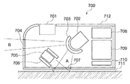
図7は、図6の入力装置で使用される指示具の構成を概略的に示す図である。 FIG. 7 is a diagram schematically showing the configuration of the pointing tool used in the input device of FIG.
図7において、指示具700は、スイッチ701、投光用LED702、所定方向へ光を投射するレンズ703、所定波長を通過するフィルタ704及び707、イメージセンサ705、外乱光を避けるためのフード706を備える。また、指示具700は、本体608側に2次元座標に相当する相対データを送信する送信部708、動作を制御する制御回路709、電源710、筐体712を備える。
In FIG. 7, an
LED702から投光された光は、レンズ703及びフィルタ707を介して、入力面711に投影し、イメージンセンサ705は入力面711の結像パターンから指示具700の移動方向及び移動量を算出する。
The light projected from the
以上の動作は、2次元座標を算出、出力する場合で、3次元座標を算出、出力する場合は、次のように動作する。 The above operations are performed when calculating and outputting two-dimensional coordinates. When calculating and outputting three-dimensional coordinates, the following operations are performed.
3次元入力する場合は、指示具700を持ち上げて、表示装置601に指示具700を向けることで、表示装置601の画面に対して指示操作を行う。そのとき、指示具700のLED702からの投光はレンズ703及びフィルタ704を介して、撮像装置1(611)及び2(612)で検出される。
In the case of three-dimensional input, the
制御回路709では、LED702を駆動すると同時に、送信部708で現在の指示具700による入力が2次元なのか3次元なのかをデータとして本体608に出力する。尚、2次元座標と3次元座標の切り替えは、先述したと同様に、イメージセンサ705で検出する輝度分布によって判断することができる。
In the
上記以外でも例えば、カメラに内蔵した赤外線LEDを光源として、発光したパルスが物体に当たって反射して戻ってきた時間を計測して物体との距離を計測する方式であっても3次元データを測定することができるので、この方式を用いてもよい。指示具700の3次元空間における座標が算出できるものであれば方式は問わない。
Other than the above, for example, three-dimensional data is measured even when the infrared LED incorporated in the camera is used as a light source and the distance from the object is measured by measuring the time when the emitted pulse hits the object and is reflected back. This method may be used. Any method can be used as long as the coordinates of the
また、距離検出部113における距離検出の方法は、イメージセンサが検出するデータの輝度分布で判定したが、指示具と入力面とが接しているか否かを検出することが可能であればよいので、例えば抵抗膜などを指示具の底面に構成して検出してもよい。 Moreover, although the distance detection method in the distance detection unit 113 is determined based on the luminance distribution of the data detected by the image sensor, it is sufficient if it is possible to detect whether the pointing tool is in contact with the input surface. For example, a resistance film or the like may be configured on the bottom surface of the pointing tool for detection.
また、2次元入力と3次元入力を切り替える際に座標軸の交換を行う内容の説明をしたが、3次元座標のデータのうち2軸のデータのみを出力する構成としてもよい。指示具と入力面の距離によって、出力する座標の形態(またはモード)が変更する構成であれば、本発明の内容に包含される。例えば、指示具を入力面から持ち上げた場合は、回転方向のデータのみの出力に変更するなども上記に該当する。 In addition, the content of exchanging the coordinate axes when switching between the two-dimensional input and the three-dimensional input has been described. However, only two-axis data among the three-dimensional coordinate data may be output. Any configuration in which the form (or mode) of the output coordinates changes depending on the distance between the pointing tool and the input surface is included in the content of the present invention. For example, when the pointing tool is lifted from the input surface, the output may be changed to output only the data in the rotation direction.
以上のように、本発明を適用すれば、表示装置の画面内容が、2次元画像と3次元オブジェクトが混在する内容であっても、指示具の入力が2次元座標入力と3次元座標入力の両方を直感的にかつ連続的に操作することができる入力装置を提供することが可能となる。 As described above, when the present invention is applied, even if the screen content of the display device is a content in which a two-dimensional image and a three-dimensional object are mixed, the input of the pointing tool is a two-dimensional coordinate input and a three-dimensional coordinate input. It is possible to provide an input device that can operate both intuitively and continuously.
また、本発明の目的は、実施の形態の機能を実現するソフトウェアのプログラムコードを記録した記憶媒体を、システムまたは装置に供給し、そのシステムまたは装置のコンピュータ(またはCPUやMPU等)が記憶媒体に格納されたプログラムコードを読み出して実行することによっても達成される。 In addition, an object of the present invention is to supply a storage medium in which a program code of software for realizing the functions of the embodiment is recorded to a system or apparatus, and a computer (or CPU, MPU, etc.) of the system or apparatus stores the storage medium It is also achieved by reading out and executing the program code stored in.
この場合、記憶媒体から読み出されたプログラムコード自体が前述した実施の形態の機能を実現することになり、そのプログラムコード及び該プログラムコードを記憶した記憶媒体は本発明を構成することになる。 In this case, the program code itself read from the storage medium realizes the functions of the above-described embodiments, and the program code and the storage medium storing the program code constitute the present invention.
また、プログラムコードを供給するための記憶媒体としては、例えば、フロッピー(登録商標)ディスク、ハードディスク、光磁気ディスク、CD−ROM、CD−R、CD−RW、DVD−ROM、DVD−RAM、DVD−RW、DVD+RW、磁気テープ、不揮発性のメモリカード、ROM等を用いることができる。または、プログラムコードをネットワークを介してダウンロードしてもよい。 Examples of the storage medium for supplying the program code include a floppy (registered trademark) disk, a hard disk, a magneto-optical disk, a CD-ROM, a CD-R, a CD-RW, a DVD-ROM, a DVD-RAM, and a DVD. -RW, DVD + RW, magnetic tape, nonvolatile memory card, ROM, etc. can be used. Alternatively, the program code may be downloaded via a network.
また、コンピュータが読み出したプログラムコードを実行することにより、上記実施の形態の機能が実現されるだけでなく、そのプログラムコードの指示に基づき、コンピュータ上で稼動しているOS(オペレーティングシステム)等が実際の処理の一部または全部を行い、その処理によって前述した実施の形態の機能が実現される場合も含まれる。 Further, by executing the program code read by the computer, not only the functions of the above-described embodiments are realized, but also an OS (operating system) running on the computer based on the instruction of the program code. A case where part or all of the actual processing is performed and the functions of the above-described embodiments are realized by the processing is also included.
更に、記憶媒体から読み出されたプログラムコードが、コンピュータに挿入された機能拡張ボードやコンピュータに接続された機能拡張ユニットに備わるメモリに書き込まれた後、そのプログラムコードの指示に基づき、その機能拡張ボードや機能拡張ユニットに備わるCPU等が実際の処理の一部または全部を行い、その処理によって前述した実施の形態の機能が実現される場合も含まれる。 Further, after the program code read from the storage medium is written in a memory provided in a function expansion board inserted into the computer or a function expansion unit connected to the computer, the function expansion is performed based on the instruction of the program code. This includes the case where the CPU or the like provided in the board or the function expansion unit performs part or all of the actual processing and the functions of the above-described embodiments are realized by the processing.
101 表示装置
102 ビデオ装置
103 周辺装置
104 CPU
105 記憶装置
106 カーソル制御装置
107 座標受信部
108 本体
109 3次元座標検出部(3次元座標出力手段)
110 座標制御処理装置(座標制御処理手段)
111 座標送信部
112 2次元座標検出部(2次元座標出力手段)
113 距離検出部(距離検出手段;触検出手段)
114 入力装置
115 スイッチ0
116 スイッチ1
117 スイッチ2
118 スイッチ3
610 座標演算回路(座標演算手段)
101
105
110 Coordinate control processing device (coordinate control processing means)
111 Coordinate
113 Distance detection unit (distance detection means; touch detection means)
114
116
117
118
610 Coordinate calculation circuit (coordinate calculation means)
Claims (14)
2次元画像情報に対して2次元の座標を出力する2次元座標出力手段と、
3次元オブジェクトに対して3次元の座標を出力する3次元座標出力手段と、
前記2次元座標出力手段の座標入力平面からの距離を検出する距離検出手段と、
前記距離検出手段が検出する距離が所定値以上の場合に前記3次元座標出力手段の座標を有効とする座標制御処理手段と、
を備えることを特徴とする入力装置。 In an input device capable of inputting instructions for image information displayed on the display device,
2D coordinate output means for outputting 2D coordinates for 2D image information;
3D coordinate output means for outputting 3D coordinates to a 3D object;
Distance detecting means for detecting a distance from the coordinate input plane of the two-dimensional coordinate output means;
Coordinate control processing means for validating the coordinates of the three-dimensional coordinate output means when the distance detected by the distance detection means is a predetermined value or more;
An input device comprising:
入力面に対して発光する発光手段と、
前記入力面からの反射光を受光して像を検出する第1の受光手段と、
前記検出された像に基づき、2次元座標演算を行う2次元座標演算手段と、
前記発光手段の発光を表示装置近傍に配置した第2の受光手段によって検出し、
前記第2の受光手段の検出結果に基づき、3次元座標演算を行う3次元座標演算手段と、
を備えることを特徴とする請求項1記載の入力装置。 The two-dimensional coordinate output means includes:
Light emitting means for emitting light to the input surface;
First light receiving means for detecting an image by receiving reflected light from the input surface;
Two-dimensional coordinate calculation means for performing two-dimensional coordinate calculation based on the detected image;
The light emission of the light emitting means is detected by a second light receiving means arranged in the vicinity of the display device,
Three-dimensional coordinate calculation means for performing three-dimensional coordinate calculation based on the detection result of the second light receiving means;
The input device according to claim 1, further comprising:
3軸からなるセンサ座標系の回転角速度を示す信号を出力する複数のジャイロと、
3軸からなるセンサ座標系の加速度を示す信号を出力する複数の加速度センサと、
前記回転角速度及び加速度に基づき、3次元座標演算を行う3次元座標演算手段と、
を備えることを特徴とする請求項1記載の入力装置。 The three-dimensional coordinate output means includes:
A plurality of gyros that output a signal indicating a rotational angular velocity of a sensor coordinate system including three axes;
A plurality of acceleration sensors that output signals indicating acceleration in a sensor coordinate system composed of three axes;
Three-dimensional coordinate calculation means for performing three-dimensional coordinate calculation based on the rotational angular velocity and acceleration;
The input device according to claim 1, further comprising:
自身が所在する空間上の3次元座標を出力する3次元座標出力手段と、
自身が所定の入力面に接触しているかどうかを検出する接触検出手段と、
前記接触検出手段の検出結果において、接触していると判断した場合には、前記3次元座標出力手段が出力可能な3軸の座標のうち2軸の座標を出力し、接触していないと判断した場合には、前記3次元座標出力手段が出力する3軸の座標のうち前記2軸の座標を前記表示装置の画面と同一平面方向に変換して出力する座標演算手段と、
を備えることを特徴とする入力装置。 In an input device capable of inputting instructions for image information displayed on the display device,
3D coordinate output means for outputting 3D coordinates on the space in which the device is located;
Contact detection means for detecting whether or not it is in contact with a predetermined input surface;
In the detection result of the contact detection means, when it is determined that the contact is made, two-axis coordinates among the three-axis coordinates that can be output by the three-dimensional coordinate output means are output, and it is determined that the contact is not made. In this case, the coordinate calculation means for converting the two-axis coordinates out of the three-axis coordinates output by the three-dimensional coordinate output means in the same plane direction as the screen of the display device,
An input device comprising:
2次元画像情報に対して2次元の座標を出力する2次元座標出力ステップと、
3次元オブジェクトに対して3次元の座標を出力する3次元座標出力ステップと、
前記2次元座標出力ステップの座標入力平面からの距離を検出する距離検出ステップと、
前記距離検出ステップが検出する距離が所定値以上の場合に前記3次元座標出力ステップの座標を有効とする座標制御処理ステップと、
を備えることを特徴とする入力方法。 In an input method capable of inputting instructions for image information displayed on a display device,
A two-dimensional coordinate output step for outputting two-dimensional coordinates for the two-dimensional image information;
A 3D coordinate output step for outputting 3D coordinates to the 3D object;
A distance detection step of detecting a distance from the coordinate input plane of the two-dimensional coordinate output step;
A coordinate control processing step for validating the coordinates of the three-dimensional coordinate output step when the distance detected by the distance detection step is a predetermined value or more;
An input method comprising:
自身が所在する空間上の3次元座標を出力する3次元座標出力ステップと、
自身が所定の入力面に接触しているかどうかを検出する接触検出ステップと、
前記接触検出ステップの検出結果において、接触していると判断した場合には、前記3次元座標出力ステップが出力可能な3軸の座標のうち2軸の座標を出力し、接触していないと判断した場合には、前記3次元座標出力ステップが出力する3軸の座標のうち前記2軸の座標を前記表示装置の画面と同一平面方向に変換して出力する座標演算ステップと、
を備えることを特徴とする入力方法。 In an input method capable of inputting instructions for image information displayed on a display device,
A three-dimensional coordinate output step for outputting three-dimensional coordinates on the space in which it is located;
A contact detection step for detecting whether or not it is in contact with a predetermined input surface;
In the detection result of the contact detection step, when it is determined that contact is made, two-axis coordinates among the three-axis coordinates that can be output by the three-dimensional coordinate output step are output, and it is determined that no contact is made. In this case, a coordinate calculation step of converting the two-axis coordinates out of the three-axis coordinates output by the three-dimensional coordinate output step into the same plane direction as the screen of the display device and outputting the coordinates,
An input method comprising:
2次元画像情報に対して2次元の座標を出力する2次元座標出力モジュールと、
3次元オブジェクトに対して3次元の座標を出力する3次元座標出力モジュールと、
前記2次元座標出力モジュールの座標入力平面からの距離を検出する距離検出モジュールと、
前記距離検出モジュールが検出する距離が所定値以上の場合に前記3次元座標出力モジュールの座標を有効とする座標制御処理モジュールと、
をコンピュータに実行させることを特徴とする入力プログラム。 In an input program that can input instructions for image information displayed on a display device,
A two-dimensional coordinate output module that outputs two-dimensional coordinates for two-dimensional image information;
A 3D coordinate output module for outputting 3D coordinates to a 3D object;
A distance detection module for detecting a distance from the coordinate input plane of the two-dimensional coordinate output module;
A coordinate control processing module that validates the coordinates of the three-dimensional coordinate output module when the distance detected by the distance detection module is greater than or equal to a predetermined value;
An input program for causing a computer to execute.
自身が所在する空間上の3次元座標を出力する3次元座標出力モジュールと、
自身が所定の入力面に接触しているかどうかを検出する接触検出モジュールと、
前記接触検出モジュールの検出結果において、接触していると判断した場合には、前記3次元座標出力モジュールが出力可能な3軸の座標のうち2軸の座標を出力し、接触していないと判断した場合には、前記3次元座標出力モジュールが出力する3軸の座標のうち前記2軸の座標を前記表示装置の画面と同一平面方向に変換して出力する座標演算モジュールと、
をコンピュータに実行させることを特徴とする入力プログラム。 In an input program that can input instructions for image information displayed on a display device,
A three-dimensional coordinate output module that outputs three-dimensional coordinates on the space in which it is located;
A contact detection module that detects whether or not it is in contact with a predetermined input surface;
In the detection result of the contact detection module, when it is determined that it is in contact, two coordinates among the three axes that can be output by the three-dimensional coordinate output module are output, and it is determined that there is no contact. In this case, a coordinate calculation module that converts the two-axis coordinates out of the three-axis coordinates output by the three-dimensional coordinate output module into the same plane direction as the screen of the display device,
An input program for causing a computer to execute.
Priority Applications (1)
| Application Number | Priority Date | Filing Date | Title |
|---|---|---|---|
| JP2006224355A JP2008047047A (en) | 2006-08-21 | 2006-08-21 | Input device, method and program and storage medium |
Applications Claiming Priority (1)
| Application Number | Priority Date | Filing Date | Title |
|---|---|---|---|
| JP2006224355A JP2008047047A (en) | 2006-08-21 | 2006-08-21 | Input device, method and program and storage medium |
Publications (2)
| Publication Number | Publication Date |
|---|---|
| JP2008047047A true JP2008047047A (en) | 2008-02-28 |
| JP2008047047A5 JP2008047047A5 (en) | 2009-10-08 |
Family
ID=39180694
Family Applications (1)
| Application Number | Title | Priority Date | Filing Date |
|---|---|---|---|
| JP2006224355A Pending JP2008047047A (en) | 2006-08-21 | 2006-08-21 | Input device, method and program and storage medium |
Country Status (1)
| Country | Link |
|---|---|
| JP (1) | JP2008047047A (en) |
Cited By (8)
| Publication number | Priority date | Publication date | Assignee | Title |
|---|---|---|---|---|
| JP2008134793A (en) * | 2006-11-28 | 2008-06-12 | Fujifilm Corp | Electronic handwriting input device |
| JP2009223839A (en) * | 2008-03-19 | 2009-10-01 | Ricoh Co Ltd | Pen type input device and handwriting input method |
| JP2009238004A (en) * | 2008-03-27 | 2009-10-15 | Smk Corp | Pointing device |
| JP2009265897A (en) * | 2008-04-24 | 2009-11-12 | Sony Corp | Hand-held information processor, controller, control system and control method |
| JP2013025666A (en) * | 2011-07-25 | 2013-02-04 | Sony Corp | Information processor, information processing method and input device |
| JP2013064770A (en) * | 2011-09-15 | 2013-04-11 | Sony Corp | Display controller and display control method |
| US9218104B2 (en) | 2013-05-14 | 2015-12-22 | Kabushiki Kaisha Toshiba | Image processing device, image processing method, and computer program product |
| CN114727075A (en) * | 2021-01-06 | 2022-07-08 | 成都极米科技股份有限公司 | Projection control method and device, projection equipment and storage medium |
Citations (2)
| Publication number | Priority date | Publication date | Assignee | Title |
|---|---|---|---|---|
| JPH0329017A (en) * | 1989-06-19 | 1991-02-07 | Internatl Business Mach Corp <Ibm> | Mouse for data input |
| JPH08272528A (en) * | 1995-03-31 | 1996-10-18 | Oki Electric Ind Co Ltd | Three-dimensional position detector |
-
2006
- 2006-08-21 JP JP2006224355A patent/JP2008047047A/en active Pending
Patent Citations (2)
| Publication number | Priority date | Publication date | Assignee | Title |
|---|---|---|---|---|
| JPH0329017A (en) * | 1989-06-19 | 1991-02-07 | Internatl Business Mach Corp <Ibm> | Mouse for data input |
| JPH08272528A (en) * | 1995-03-31 | 1996-10-18 | Oki Electric Ind Co Ltd | Three-dimensional position detector |
Cited By (9)
| Publication number | Priority date | Publication date | Assignee | Title |
|---|---|---|---|---|
| JP2008134793A (en) * | 2006-11-28 | 2008-06-12 | Fujifilm Corp | Electronic handwriting input device |
| JP2009223839A (en) * | 2008-03-19 | 2009-10-01 | Ricoh Co Ltd | Pen type input device and handwriting input method |
| JP2009238004A (en) * | 2008-03-27 | 2009-10-15 | Smk Corp | Pointing device |
| JP2009265897A (en) * | 2008-04-24 | 2009-11-12 | Sony Corp | Hand-held information processor, controller, control system and control method |
| JP2013025666A (en) * | 2011-07-25 | 2013-02-04 | Sony Corp | Information processor, information processing method and input device |
| JP2013064770A (en) * | 2011-09-15 | 2013-04-11 | Sony Corp | Display controller and display control method |
| US9218104B2 (en) | 2013-05-14 | 2015-12-22 | Kabushiki Kaisha Toshiba | Image processing device, image processing method, and computer program product |
| CN114727075A (en) * | 2021-01-06 | 2022-07-08 | 成都极米科技股份有限公司 | Projection control method and device, projection equipment and storage medium |
| CN114727075B (en) * | 2021-01-06 | 2023-09-08 | 成都极米科技股份有限公司 | Projection control method and device, projection equipment and storage medium |
Similar Documents
| Publication | Publication Date | Title |
|---|---|---|
| US10698502B2 (en) | Multi-sensor device with an accelerometer for enabling user interaction through sound or image | |
| JP2008047047A (en) | Input device, method and program and storage medium | |
| JP4751365B2 (en) | pointing device | |
| US20150049019A1 (en) | Control device, input device, control system, handheld device, and control method | |
| JP5561092B2 (en) | INPUT DEVICE, INPUT CONTROL SYSTEM, INFORMATION PROCESSING METHOD, AND PROGRAM | |
| EP2144142A2 (en) | Input apparatus using motions and user manipulations and input method applied to such input apparatus | |
| JP2003280785A (en) | Image display processor, image display processing method and computer program | |
| JP7386152B2 (en) | Input system and input method | |
| KR100739980B1 (en) | Inertial sensing input apparatus | |
| JP2008158842A (en) | Map display device | |
| WO2017222858A1 (en) | Integrated free space and surface input device | |
| WO2019178531A1 (en) | Systems and methods for motion-based control of ultrasound images | |
| EP3032380A1 (en) | Image projection apparatus, and system employing interactive input-output capability | |
| JP6373537B1 (en) | Spatial position indication system | |
| US20100259475A1 (en) | Angle sensor-based pointer and a cursor control system with the same | |
| JP2006323454A (en) | Three-dimensional instruction input system, three-dimensional instruction input device, three-dimensional instruction input method, and program | |
| KR100601001B1 (en) | Computer input apparatus using gyro and ultrasonic | |
| KR20080017194A (en) | Wireless mouse and driving method thereof | |
| KR20180007569A (en) | 3-dimensional mouse using rotary sensor |
Legal Events
| Date | Code | Title | Description |
|---|---|---|---|
| A521 | Request for written amendment filed |
Free format text: JAPANESE INTERMEDIATE CODE: A523 Effective date: 20090821 |
|
| A621 | Written request for application examination |
Free format text: JAPANESE INTERMEDIATE CODE: A621 Effective date: 20090821 |
|
| A977 | Report on retrieval |
Free format text: JAPANESE INTERMEDIATE CODE: A971007 Effective date: 20110602 |
|
| A131 | Notification of reasons for refusal |
Free format text: JAPANESE INTERMEDIATE CODE: A131 Effective date: 20110621 |
|
| A521 | Request for written amendment filed |
Free format text: JAPANESE INTERMEDIATE CODE: A523 Effective date: 20110822 |
|
| A02 | Decision of refusal |
Free format text: JAPANESE INTERMEDIATE CODE: A02 Effective date: 20111214 |