JP2008043247A - Apparatus for forming pizza dough and method for forming pizza dough using the forming apparatus - Google Patents
Apparatus for forming pizza dough and method for forming pizza dough using the forming apparatus Download PDFInfo
- Publication number
- JP2008043247A JP2008043247A JP2006221631A JP2006221631A JP2008043247A JP 2008043247 A JP2008043247 A JP 2008043247A JP 2006221631 A JP2006221631 A JP 2006221631A JP 2006221631 A JP2006221631 A JP 2006221631A JP 2008043247 A JP2008043247 A JP 2008043247A
- Authority
- JP
- Japan
- Prior art keywords
- pizza dough
- forming
- base
- expansion
- dough
- Prior art date
- Legal status (The legal status is an assumption and is not a legal conclusion. Google has not performed a legal analysis and makes no representation as to the accuracy of the status listed.)
- Granted
Links
Images


Landscapes
- Manufacturing And Processing Devices For Dough (AREA)
- Bakery Products And Manufacturing Methods Therefor (AREA)
Abstract
Description
本発明は、ピザ生地の成形装置及びこの成形装置を使用したピザ生地の成形方法に関するものであり、より詳細には、ピザ生地を大量に生産する際に、手作りと同じように生地を外側に引き延ばして成形することによって、手作りと同じ食感の得られるピザ生地の成形装置及びこの成形装置を使用したピザ生地の成形方法に関するものである。 TECHNICAL FIELD The present invention relates to a pizza dough forming apparatus and a pizza dough forming method using the forming apparatus, and more specifically, when producing pizza dough in large quantities, the dough is placed outside like handmade. The present invention relates to a pizza dough forming apparatus that can obtain the same texture as handmade by stretching and forming, and a pizza dough forming method using this forming apparatus.
ピザ生地は、広く知られているように、生地を外側に引き延ばして円形に成形するものであり、通常、外縁部に比べて中央部が薄くなるように成形している。このため、手作りでピザ生地を成形するときには、生地を外側に引き延ばして成形した後で、空中で回転させるなどのパフォーマンスを行って中央部が薄くなるように成形している。 As is well known, the pizza dough is formed by extending the dough to the outside and forming it in a circular shape, and is usually formed so that the center portion is thinner than the outer edge portion. For this reason, when forming pizza dough by hand, the dough is stretched outward and then formed into a thin central portion by performing a performance such as rotating in the air.
ピザ生地を大量に機械生産する際にも、手作りと同じ食感を得るように成形するためには、手作りと同じように生地を外側に引き延ばして成形し、外縁部に比べて中央部が薄くなるように成形することが望ましい。特に、ナポリスタイルのピザ生地では、外縁部を肉厚にするのが特徴となっている。しかしながら、従来技術では特許文献1の図8等に示されるように、単にプレスで押さえて成形するのみのものだったので、形状はほぼ同じに成形することはできても、手作りのピザ生地と同様に、外側に引き延ばして成形するものと同じ食感のピザ生地を得ることは、非常に困難であった。 Even when mass-producing pizza dough, in order to obtain the same texture as handmade, the dough is stretched outward as in handmade, and the center is thinner than the outer edge. It is desirable to mold so that In particular, Naples-style pizza dough is characterized by a thick outer edge. However, in the prior art, as shown in FIG. 8 of Patent Document 1, etc., since it was simply formed by pressing with a press, the shape can be almost the same, but handmade pizza dough and Similarly, it has been very difficult to obtain a pizza dough having the same texture as that formed by stretching outward.
本発明は、このような従来技術の問題点を解消して、手作りのピザ生地と同様に外側に引き延ばして生地を成形し、手作りのものと同じ食感のピザ生地を得ることを目的とするものである。 An object of the present invention is to solve such problems of the prior art and to form the dough by stretching outward like a handmade pizza dough, and to obtain a pizza dough having the same texture as a handmade one Is.
上記課題を解決するために、本発明は、中心位置に固定された中央台と、この中央台の周囲に配置され、複数個に分割されて外方に向かって放射状に移動する拡張台と、この拡張台を外方に向かって放射状に移動させる拡張台移動装置とを有することを特徴とするピザ生地の成形装置を提供するものである。 In order to solve the above problems, the present invention comprises a central platform fixed at a central position, an expansion platform that is arranged around the central platform, is divided into a plurality, and moves radially outwardly, An apparatus for forming a pizza dough characterized by having an expansion table moving device that moves the expansion table radially outward.
ここで、前記拡張台移動装置が、中央に孔の設けられたドーナツ状の円板と、このドーナツ状の円板に放射状に移動可能に配設された複数個の案内軸と、この複数個の案内軸を外方に向かって放射状に一斉に移動させる拡張台駆動源とを有することが好ましく、さらに、前記拡張台駆動源が、上下方向に移動する円錐カムと、前記案内軸の内側端部に設けられ、前記円錐カムに係合するカムフォロアと、このカムフォロアを前記円錐カムに向けて付勢する付勢手段とからなることが好ましい。また、前記円錐カムが、速度制御された微速シリンダによって上下方向に移動することが好ましい。 Here, the expansion table moving device includes a donut-shaped disk having a hole in the center, a plurality of guide shafts radially arranged on the donut-shaped disk, and the plurality of guide shafts. And an extension base drive source that simultaneously moves the guide shafts radially outward, and the extension base drive source further includes a conical cam that moves in the vertical direction and an inner end of the guide shaft. It is preferable that the cam follower is provided at a portion and engages with the conical cam, and an urging means for urging the cam follower toward the conical cam. The conical cam is preferably moved in the vertical direction by a speed-controlled fine speed cylinder.
また、前記拡張台が、前記案内軸に固定されたセグメント状の支持片の集合体であることが好ましく、さらに、前記セグメント状の支持片が、前記案内軸に固定されており、縮径したときに、前記中央台と前記セグメント状の支持片とで実質的に単一の円板の形状となることが好ましい。 The expansion base is preferably an assembly of segment-like support pieces fixed to the guide shaft, and the segment-like support pieces are fixed to the guide shaft and have a reduced diameter. In some cases, it is preferable that the central platform and the segment-shaped support pieces have a substantially single disk shape.
さらに、上記課題を解決するために、本発明は、中心位置に固定された中央台と、この中央台の周囲に配置され、複数個に分割されて外方に向かって放射状に移動可能な拡張台との全面にピザ生地が載置された後、前記拡張台を外方に向かって放射状に移動させることにより前記ピザ生地を延伸することを特徴とするピザ生地の成形方法を提供するものである。 Furthermore, in order to solve the above-mentioned problems, the present invention provides a central base fixed at a central position, and an expansion that is arranged around the central base and is divided into a plurality of pieces and is movable radially outward. After the pizza dough is placed on the entire surface of the table, a method for forming the pizza dough is provided, wherein the pizza dough is stretched by moving the expansion table radially outward. is there.
ここで、前記ピザ生地は、縮径した状態の前記拡張台の外径よりわずかに大きく成形され、縮径した状態の前記拡張台の外周に外縁部を垂らして載置されることが好ましい。 Here, it is preferable that the pizza dough is formed to be slightly larger than the outer diameter of the expansion base in a reduced state and is placed with an outer edge portion hanging down on the outer periphery of the expansion base in a reduced diameter state.
本発明は、以上のように構成されているので、大量に機械生産するピザ生地でありながら、手作りと同じように生地を外側に引き延ばして成形し、かつ、外縁部に比べて中央部が薄くなるように成形することができ、それにより、手作りのピザ生地と同じ食感を得るように成形することができる。 Since the present invention is configured as described above, although it is a pizza dough that is mass-produced in a machine, it is formed by stretching the dough to the outside in the same manner as handmade, and the central portion is thinner than the outer edge portion. Can be shaped so that it has the same texture as a handmade pizza dough.
以下に、本発明に係るピザ生地の成形装置及びこの成形装置を使用したピザ生地の成形方法について、添付の図面に示す好適な実施形態に基づいて詳細に説明する。図1ないし図4は、本発明の実施形態に係るピザ生地の成形装置の一実施形態を概念的に示す図面であって、図1は縮径したときの平面部分断面図、図2は縮径したときの正面断面図、図3は延伸したときの平面部分断面図、図4は延伸したときの正面断面図である。また、図5はセグメント状に形成された支持片の詳細図、図6は拡張台移動装置の詳細を示す図2の部分拡大図である。 DESCRIPTION OF EMBODIMENTS Hereinafter, a pizza dough forming apparatus and a pizza dough forming method using the forming apparatus according to the present invention will be described in detail based on preferred embodiments shown in the accompanying drawings. FIG. 1 to FIG. 4 are drawings conceptually showing an embodiment of a pizza dough forming apparatus according to an embodiment of the present invention. FIG. 1 is a plan partial sectional view when the diameter is reduced, and FIG. FIG. 3 is a partial front sectional view when stretched, and FIG. 4 is a front sectional view when stretched. FIG. 5 is a detailed view of a support piece formed in a segment shape, and FIG. 6 is a partially enlarged view of FIG. 2 showing details of the extension table moving device.
図1ないし図4及び図6に示すように、本発明のピザ生地の成形装置10は、中心位置に固定された中央台12が設けられており、この中央台12の周囲に、複数個(実施例では8個)に分割されて外方に向かって放射状に移動する拡張台14が配置されている。そして、図2及び図4に示すように、この中央台12と拡張台14との上面にピザ生地16を載せて、複数個に分割された拡張台14を、それぞれ外方に向かって放射状に移動することによってピザ生地16を外側に向かって延伸するように構成されている。
As shown in FIG. 1 to FIG. 4 and FIG. 6, the pizza
この拡張台14を外方に向かって放射状に移動させるために、拡張台14の下方には、拡張台移動装置18が設けられている。この拡張台移動装置18は、中央に孔の設けられたドーナツ状の円板20を有しており、このドーナツ状の円板20に放射状に設けられた複数個の貫通孔22にそれぞれ案内軸24が挿入されている。この案内軸24の数は、拡張台14の分割数と同数であり、この実施例では8個となっている。
In order to move the
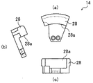
さらに、案内軸24の内側端部には、詳細は後述するカムフォロア26を介して、セグメント状に形成されたピザ生地の支持片28が取り付けられている。この支持片28は、図5に示す形状であって、中央台12の外側に環状に配置されており、この支持片28の集合体が全体として環状の拡張台14を構成している。この拡張台14の分割数は、この実施例では8分割であるが、8分割に限定されるものではなく、6〜12個程度に分割することが望ましい。6個以上とすることで、延伸成形後のピザ生地16をほぼ均整のとれた円形とすることができる。また、その数を増やすほどきれいな円形に近付くが、部品点数の削減の観点からは、12個程度以下とするのがよい。
Further, a pizza
支持片28は、ピザ生地に直接接触し、延伸の作用を及ぼす部材である。このような支持片28の少なくともピザ生地と接触する部分は、食品衛生法に準じた材質であって、ピザ生地の張り付きが少なく、かつピザ生地を引っ張るための適度な摩擦力を有するものを用いるのが好ましい。例えば、ジュラコン等を用いることができる。
The
図2及び図4に示すように、この拡張台移動装置18は、拡張台駆動源30によって移動される。拡張台駆動源30は、円錐カム32と、カムフォロア26と、カムフォロア26を円錐カム32に向けて付勢する付勢手段とを有している。以下、拡張台駆動源30について説明する。
As shown in FIGS. 2 and 4, the extension
円板20の中央の下側には、上下方向に移動する円錐カム32が設けられている。この円錐カム32は、微速シリンダ34によって上下方向に移動する。この微速シリンダ34は、図示しないスピードコントローラなどの任意の速度制御手段によって、ピザ生地を引き延ばすのに適した速度でゆっくりと上昇するように速度制御される。
A
案内軸24の外側端部近傍には、案内軸24の内側端部に設けられたカムフォロア26を円錐カム32の中心軸に向けて略水平に付勢する付勢手段が設けられている。この付勢手段は案内軸24を内側に向けて付勢する圧縮コイルばね36と、この圧縮コイルばね36を支持する支持管38とからなっている。支持管38は、円板20の外周の貫通孔22に対応する位置に放射状に取り付けられており、圧縮コイルばね36は、貫通孔22に挿入された案内軸24の外側端面と支持管38の外側の内端面との間に装填されている。付勢手段は、圧縮コイルばね36によって、常に案内軸24を内側に向けて付勢する。
In the vicinity of the outer end portion of the
なお、この付勢手段は、円錐カム32による案内軸24の移動量(ストローク)に対応し、その移動量の間でカムフォロア26が円錐カム32に柔軟に追随する程度の力で案内軸24(カムフォロア26)を付勢できるものであればよく、圧縮コイルばねを用いるもの以外にも、ガスシリンダを用いるもの等であってもよい。
This urging means corresponds to the movement amount (stroke) of the
案内軸24の内側端部には、カムフォロア26が設けられている。このカムフォロア26は、支持片28とは反対側の端部(図2における下側端部)にカムローラ36を有しており、カムローラ36は、円形カム32に接する接触するように配置されている。上述のように、カムフォロア26は、円錐カム32の中心に向けて常に付勢されているので、カムローラ36は、常に円錐カム32に当接(係合)している。このように、カムフォロア26は、常に円錐カム32に当接するように付勢されており、円錐カム32が上下動することによって、案内軸24が放射状に往復動し、案内軸24にカムフォロア26を介して取り付けられているセグメント状に形成されたピザ生地の支持片28が、外側に向かって放射状に拡縮する。
A
拡張台駆動源30は、以上のように構成されているので、円錐カム32が微速シリンダ34によってゆっくりとした速度で上昇することによって、案内軸24の内側に設けられたカムフォロア26の先端のカムローラ36が外側に移動し、図6に想像線で描かれているように、それぞれの案内軸24が外方に向かって放射状に移動する。
Since the extension
そして、この移動によって、案内軸24にカムフォロア26を介して固定された、複数個のセグメント状のピザ生地の支持片28からなる拡張台14がゆっくりと外方に向かって移動して、図3及び図4に示す位置、図6では想像線で示した位置まで放射状に拡がり、ピザ生地16を外側に向かって延伸して所定のピザ生地の寸法に成形する。
As a result of this movement, the
このとき、円錐カム32の上昇する速度は、ピザ生地16が引き延ばされるのに最適な速度で拡張台14の支持片28が外側に向かって放射状に延伸するように設定されることが望ましく、この速度で円錐カム32がゆっくりと上昇するように、微速シリンダ34の上昇速度をスピードコントローラなどの任意の速度制御手段によって調整する。
At this time, it is desirable that the rising speed of the
なお、図3及び図4に示す位置、図6では想像線で示した位置から拡張台14が縮径するときには、延伸して成形したピザ生地が取り出されて拡張台14上には何も存在しないので、速度制御して微速シリンダ34をゆっくり下降させる必要はない。
When the
セグメント状の支持片28は、縮径したときには、図2に示すように、その内径(内周面)28a(図5参照)が中央台12の外周に近接する位置まで縮径して、セグメント状の支持片28と中央台12とで実質的に単一の円板の形状となるように構成されている。また、中心位置に固定された中央台12は、ドーナツ状の円板20に支持板42で固定されており、円板20は、4本の脚44で支持されている。
When the diameter of the segment-
本発明のピザ生地の成形装置は、以上に説明したように構成されているので、ピザ生地16を成形する際には、セグメント状の支持片28と中央台12とでほぼ単一の円板の形状となるように縮径した拡張台14の上に、所定の形状にあらかじめプレスで押さえて成形した材料を載せ、拡張台駆動源30の円錐カム32を微速シリンダ34によってゆっくりとした速度で上昇させることによって、案内軸24にカムフォロア26を介して固定された複数個のセグメント状のピザ生地の支持片28からなる拡張台14がゆっくりと外方に向かって延伸して、ピザ生地16を外側に向かって延伸して成形する成形方法を得ることができる。
Since the apparatus for forming pizza dough according to the present invention is configured as described above, when the
そして、このピザ生地の成形方法によれば、手作りのピザ生地と同様に、ピザ生地16を外側に引き延ばして所定の寸法のピザ生地に成形するものであり、生地を外側に向かって引き延ばすことによって、図7に示すように、外縁部に比べて中央部が薄くなるように成形することができる。図7は、ピザ生地の成形装置10によって成形されたピザ生地16の断面を模式的に示す図である。この方法によれば、手作りのピザ生地と同じ成形方法となるため、手作りの生地と同じ食感の生地を得ることができる。
And according to this pizza dough molding method, like the handmade pizza dough, the
特に、ナポリスタイルのピザ生地では、図2に示すように、縮径した状態の拡張台14の上に、外径よりわずかに大きくなるようにプレスで押さえて成形したピザ生地の材料を用いて、拡張台14の外周にピザ生地16の外縁部を垂らして載置してから延伸することによって、外周を肉厚にすることが可能になり、手作りのピザ生地と同様の形状であり、かつ手作りのピザ生地と同じように外側に引き延ばして成形するので、手作りのピザ生地と同様の食感のピザ生地を得ることができる。
In particular, in the Neapolitan style pizza dough, as shown in FIG. 2, the pizza dough material formed by pressing with a press so as to be slightly larger than the outer diameter on the
以上、本発明に係るピザ生地の成形装置及びこの成形装置を使用したピザ生地の成形方法について詳細に説明したが、本発明は上記種々の実施例に限定されず、本発明の主旨を逸脱しない範囲において、種々の改良や変更をしてもよいのはもちろんである。 The pizza dough forming apparatus and the pizza dough forming method using the forming apparatus according to the present invention have been described in detail above, but the present invention is not limited to the various embodiments described above and does not depart from the gist of the present invention. Of course, various improvements and changes may be made in the range.
10 ピザ生地の成形装置
12 中央台
14 拡張台
16 ピザ生地
18 拡張台移動装置
20 円板
22 貫通孔
24 案内軸
26 カムフォロア
28 支持片
28a 内径(内周面)
30 拡張台駆動源
32 円錐カム
34 微速シリンダ
36 圧縮コイルばね
38 支持管
40 カムローラ
42 支持板
44 脚
DESCRIPTION OF
30 Extension
Claims (8)
この中央台の周囲に配置され、複数個に分割されて外方に向かって放射状に移動する拡張台と、
この拡張台を外方に向かって放射状に移動させる拡張台移動装置とを有することを特徴とするピザ生地の成形装置。 A central platform fixed at the center,
An expansion base that is arranged around the central base and is divided into a plurality of pieces and moved radially outwardly;
An apparatus for forming a pizza dough, comprising: an expansion table moving device that moves the expansion table radially outward.
前記拡張台を外方に向かって放射状に移動させることにより前記ピザ生地を延伸することを特徴とするピザ生地の成形方法。 After the pizza dough is placed on the entire surface of the central base fixed at the center position and the expansion base that is arranged around the central base and is divided into a plurality of pieces and can be moved radially outward,
A method for forming a pizza dough, wherein the pizza dough is stretched by moving the expansion base radially outward.
Priority Applications (1)
| Application Number | Priority Date | Filing Date | Title |
|---|---|---|---|
| JP2006221631A JP4814011B2 (en) | 2006-08-15 | 2006-08-15 | Pizza dough forming apparatus and pizza dough forming method using the forming apparatus |
Applications Claiming Priority (1)
| Application Number | Priority Date | Filing Date | Title |
|---|---|---|---|
| JP2006221631A JP4814011B2 (en) | 2006-08-15 | 2006-08-15 | Pizza dough forming apparatus and pizza dough forming method using the forming apparatus |
Publications (3)
| Publication Number | Publication Date |
|---|---|
| JP2008043247A true JP2008043247A (en) | 2008-02-28 |
| JP2008043247A5 JP2008043247A5 (en) | 2009-03-05 |
| JP4814011B2 JP4814011B2 (en) | 2011-11-09 |
Family
ID=39177611
Family Applications (1)
| Application Number | Title | Priority Date | Filing Date |
|---|---|---|---|
| JP2006221631A Active JP4814011B2 (en) | 2006-08-15 | 2006-08-15 | Pizza dough forming apparatus and pizza dough forming method using the forming apparatus |
Country Status (1)
| Country | Link |
|---|---|
| JP (1) | JP4814011B2 (en) |
Cited By (3)
| Publication number | Priority date | Publication date | Assignee | Title |
|---|---|---|---|---|
| WO2015115220A1 (en) * | 2014-01-28 | 2015-08-06 | レオン自動機株式会社 | Food dough shaping method and device |
| KR20170121252A (en) * | 2015-02-28 | 2017-11-01 | 상하이 마이크로 일렉트로닉스 이큅먼트(그룹) 컴퍼니 리미티드 | Adjustable magnetic buoyancy gravity compensation device |
| CN112512323A (en) * | 2018-07-27 | 2021-03-16 | 伊克尔国际股份公司 | Improved food dough stretching machine |
Families Citing this family (1)
| Publication number | Priority date | Publication date | Assignee | Title |
|---|---|---|---|---|
| JP5844924B1 (en) * | 2015-01-29 | 2016-01-20 | 株式会社コバード | Food molding apparatus and method |
Citations (4)
| Publication number | Priority date | Publication date | Assignee | Title |
|---|---|---|---|---|
| JPS5929193A (en) * | 1982-08-11 | 1984-02-16 | Ricoh Co Ltd | Heat sensitive transfer medium |
| US4690043A (en) * | 1985-08-20 | 1987-09-01 | Pacilio Victor C | Pizza dough spreading apparatus |
| JPH06113710A (en) * | 1991-09-21 | 1994-04-26 | Barilla Ger Flli Spa | Vertical press |
| JP2006340634A (en) * | 2005-06-08 | 2006-12-21 | Nippon Flour Mills Co Ltd | Method for shaping pizza dough, and tool for shaping pizza dough usable therefor |
-
2006
- 2006-08-15 JP JP2006221631A patent/JP4814011B2/en active Active
Patent Citations (4)
| Publication number | Priority date | Publication date | Assignee | Title |
|---|---|---|---|---|
| JPS5929193A (en) * | 1982-08-11 | 1984-02-16 | Ricoh Co Ltd | Heat sensitive transfer medium |
| US4690043A (en) * | 1985-08-20 | 1987-09-01 | Pacilio Victor C | Pizza dough spreading apparatus |
| JPH06113710A (en) * | 1991-09-21 | 1994-04-26 | Barilla Ger Flli Spa | Vertical press |
| JP2006340634A (en) * | 2005-06-08 | 2006-12-21 | Nippon Flour Mills Co Ltd | Method for shaping pizza dough, and tool for shaping pizza dough usable therefor |
Cited By (6)
| Publication number | Priority date | Publication date | Assignee | Title |
|---|---|---|---|---|
| WO2015115220A1 (en) * | 2014-01-28 | 2015-08-06 | レオン自動機株式会社 | Food dough shaping method and device |
| JP2016039797A (en) * | 2014-01-28 | 2016-03-24 | レオン自動機株式会社 | Molding method and device of food dough |
| KR20170121252A (en) * | 2015-02-28 | 2017-11-01 | 상하이 마이크로 일렉트로닉스 이큅먼트(그룹) 컴퍼니 리미티드 | Adjustable magnetic buoyancy gravity compensation device |
| KR102012782B1 (en) * | 2015-02-28 | 2019-08-21 | 상하이 마이크로 일렉트로닉스 이큅먼트(그룹) 컴퍼니 리미티드 | Adjustable Magnetic Buoyancy Gravity Compensation Device |
| US10415639B2 (en) | 2015-02-28 | 2019-09-17 | Shanghai Micro Electronics Equipment (Group) Co., Ltd. | Adjustable magnetic buoyancy gravity compensator |
| CN112512323A (en) * | 2018-07-27 | 2021-03-16 | 伊克尔国际股份公司 | Improved food dough stretching machine |
Also Published As
| Publication number | Publication date |
|---|---|
| JP4814011B2 (en) | 2011-11-09 |
Similar Documents
| Publication | Publication Date | Title |
|---|---|---|
| JP4814011B2 (en) | Pizza dough forming apparatus and pizza dough forming method using the forming apparatus | |
| US8047043B2 (en) | Punch die and punch machine using the same | |
| CN110215979A (en) | A kind of processing of crude drugs smashing device | |
| EP2489988A3 (en) | Servo motor manufacturing method, servo motor manufacturing apparatus, servo motor, and encoder | |
| CN204997330U (en) | Sealing washer mounting plate | |
| JP2021167103A (en) | Take-out assisting device for injection molding die | |
| KR20170069581A (en) | Support equipment for spinning wheel apparatus of ceramics and Drying apparatus using that | |
| JP5941519B2 (en) | Method and apparatus for forming food dough | |
| CN202435214U (en) | End cover shaping tooling | |
| CN104923742A (en) | Pressure piston salt core pressing device | |
| CN205362363U (en) | Keyboard floor punching press lathe | |
| CN1278838C (en) | Precision micro plasticity shaping system | |
| JP5844924B1 (en) | Food molding apparatus and method | |
| CN203751657U (en) | Bearing press mounting device | |
| JPH04349840A (en) | Machine and method for molding | |
| CN108511375B (en) | Semiconductor wafer expander | |
| JPH0538534A (en) | Press die for forming depressed shape | |
| CN204036313U (en) | The positioner of blade inserting Impeller Shaping machine | |
| CN104401024A (en) | Plastic molding crank press | |
| CN205008484U (en) | Damper link stamping die | |
| CN206180797U (en) | Motor shell presses circle to equip | |
| CN207322710U (en) | A kind of rotating disc type sub warhead determines cloth machine | |
| CN202805528U (en) | Automatic steel sheet placing machine | |
| CN104827516B (en) | Noble metal stamp tooth limit forms device and method | |
| CN206999732U (en) | A kind of punching press mold base |
Legal Events
| Date | Code | Title | Description |
|---|---|---|---|
| A521 | Request for written amendment filed |
Free format text: JAPANESE INTERMEDIATE CODE: A523 Effective date: 20090115 |
|
| A621 | Written request for application examination |
Free format text: JAPANESE INTERMEDIATE CODE: A621 Effective date: 20090115 |
|
| A977 | Report on retrieval |
Free format text: JAPANESE INTERMEDIATE CODE: A971007 Effective date: 20110803 |
|
| TRDD | Decision of grant or rejection written | ||
| A01 | Written decision to grant a patent or to grant a registration (utility model) |
Free format text: JAPANESE INTERMEDIATE CODE: A01 Effective date: 20110823 |
|
| A01 | Written decision to grant a patent or to grant a registration (utility model) |
Free format text: JAPANESE INTERMEDIATE CODE: A01 |
|
| A61 | First payment of annual fees (during grant procedure) |
Free format text: JAPANESE INTERMEDIATE CODE: A61 Effective date: 20110825 |
|
| R150 | Certificate of patent or registration of utility model |
Free format text: JAPANESE INTERMEDIATE CODE: R150 Ref document number: 4814011 Country of ref document: JP Free format text: JAPANESE INTERMEDIATE CODE: R150 |
|
| FPAY | Renewal fee payment (event date is renewal date of database) |
Free format text: PAYMENT UNTIL: 20140902 Year of fee payment: 3 |
|
| R250 | Receipt of annual fees |
Free format text: JAPANESE INTERMEDIATE CODE: R250 |
|
| R250 | Receipt of annual fees |
Free format text: JAPANESE INTERMEDIATE CODE: R250 |
|
| R250 | Receipt of annual fees |
Free format text: JAPANESE INTERMEDIATE CODE: R250 |
|
| R250 | Receipt of annual fees |
Free format text: JAPANESE INTERMEDIATE CODE: R250 |
|
| R250 | Receipt of annual fees |
Free format text: JAPANESE INTERMEDIATE CODE: R250 |
|
| R250 | Receipt of annual fees |
Free format text: JAPANESE INTERMEDIATE CODE: R250 |
|
| R250 | Receipt of annual fees |
Free format text: JAPANESE INTERMEDIATE CODE: R250 |
|
| R250 | Receipt of annual fees |
Free format text: JAPANESE INTERMEDIATE CODE: R250 |
|
| S533 | Written request for registration of change of name |
Free format text: JAPANESE INTERMEDIATE CODE: R313533 |
|
| R350 | Written notification of registration of transfer |
Free format text: JAPANESE INTERMEDIATE CODE: R350 |
|
| R250 | Receipt of annual fees |
Free format text: JAPANESE INTERMEDIATE CODE: R250 |
|
| R250 | Receipt of annual fees |
Free format text: JAPANESE INTERMEDIATE CODE: R250 |