JP2008024145A - Transfer and supply method of liquid and vehicle for transferring liquid - Google Patents
Transfer and supply method of liquid and vehicle for transferring liquid Download PDFInfo
- Publication number
- JP2008024145A JP2008024145A JP2006198702A JP2006198702A JP2008024145A JP 2008024145 A JP2008024145 A JP 2008024145A JP 2006198702 A JP2006198702 A JP 2006198702A JP 2006198702 A JP2006198702 A JP 2006198702A JP 2008024145 A JP2008024145 A JP 2008024145A
- Authority
- JP
- Japan
- Prior art keywords
- liquid
- liquid tank
- liquids
- vehicle
- tank
- Prior art date
- Legal status (The legal status is an assumption and is not a legal conclusion. Google has not performed a legal analysis and makes no representation as to the accuracy of the status listed.)
- Pending
Links
Images

Abstract
Description
本発明は、例えば、化学薬品等、複数種の液体を混合してなる混合液の使用先への供給方法及び上記混合液の輸送に適した液体移送用車両に関する。 The present invention relates to a method for supplying a liquid mixture obtained by mixing a plurality of types of liquids, such as chemicals, to a user and a liquid transfer vehicle suitable for transporting the liquid mixture.
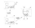
液体の輸送業務にかかる技術としては、例えば、液化ガスを包含する液体を輸送するためのタンクローリー車が提案されている(特許文献1参照)。従来から、例えば、化学薬品等の危険物の搬送業務では、タンクローリー車を用いて大量の液体を移送し、必要量の積み降ろしを実施していた。また、例えば、所望の化学薬品が複数種の液体を混合した混合液である場合、例えば、図5(a)に示すように、これら複数種の液体(液体A及び液体B)は、例えば、各製造工場101,102から別々のタンクローリー車100で使用先103まで移送され、例えば、使用先103の貯蔵タンク104等に一旦貯蔵された後、各使用先に設けられた撹拌機105によってこれら複数種の液体A,Bを撹拌(混合)して所定の化学薬品Cを得ていた。あるいは、図5(b)に示すように液体A,液体Bを、各製造工場101,102からそれぞれ撹拌機105Aが設置された所定場所106まで移送し、その場所106で複数種の液体A,Bを撹拌して所定の化学薬品Cとした後、この化学薬品を使用先103まで移送していた。その理由としては、例えば、化学薬品の場合、混合液を構成する各液体を製造しているメーカーが限られていることや、危険物である化学薬品を車両等で移動中に混合して製造することが消防法で禁止されていること等が挙げられる。
As a technique related to the liquid transportation business, for example, a tank truck for transporting a liquid containing a liquefied gas has been proposed (see Patent Document 1). Conventionally, for example, in the transportation work of dangerous materials such as chemicals, a large amount of liquid is transferred using a tank lorry vehicle, and a required amount is loaded and unloaded. Further, for example, when the desired chemical is a mixed liquid in which a plurality of types of liquids are mixed, for example, as shown in FIG. 5A, the plurality of types of liquids (liquid A and liquid B) are, for example, After being transported from each
このように各使用先等に設置されている撹拌機で複数種の液体を混合して化学薬品とすると、例えば、複数種類の化学薬品が必要な場合等に、作業が極めて煩雑化するという問題がある。すなわち、複数種の液体を混合して各化学薬品とする際には、毎回、撹拌機を洗浄しなければならないという問題がある。このため、撹拌作業が極めて煩雑になるという問題がある。なお、化学薬品以外の液体の場合であっても、同様の問題が生じる虞はある。 In this way, when a plurality of types of liquids are mixed with a stirrer installed at each use site to form chemicals, for example, when a plurality of types of chemicals are required, the work becomes extremely complicated. There is. That is, there is a problem that the stirrer must be cleaned every time when a plurality of types of liquids are mixed to form each chemical. For this reason, there exists a problem that stirring work becomes very complicated. Even in the case of liquids other than chemicals, similar problems may occur.
本発明は、このような事情に鑑みてなされたものであり、複数種の液体を効率的に移送し且つこれら複数種の液体を混合してなる混合液を効率的に使用先に供給することができる液体移送供給方法、及びこれら複数種の液体の移送に適した液体移送用車両を提供することを課題とする。 The present invention has been made in view of such circumstances, and efficiently transports a plurality of types of liquids and efficiently supplies a mixed liquid obtained by mixing the plurality of types of liquids to a user. It is an object of the present invention to provide a liquid transfer and supply method that can perform the above and a liquid transfer vehicle suitable for transferring these plural types of liquid.
上記課題を解決する本発明の第1の態様は、混合液の原料である複数種の液体を一台の車両に搭載された液体タンクに搬入して使用先まで移送し、前記液体タンク内の前記複数種の液体を当該液体タンクに設けられた撹拌装置によって撹拌して前記混合液とし、最終的に前記液体タンク内の前記混合液を前記使用先に供給することを特徴とする液体移送供給方法にある。 The first aspect of the present invention that solves the above problem is to carry a plurality of types of liquids, which are raw materials of the mixed liquid, into a liquid tank mounted on a single vehicle and transfer them to a use destination. The liquid transfer supply, wherein the plurality of kinds of liquids are stirred by a stirring device provided in the liquid tank to form the mixed liquid, and finally the mixed liquid in the liquid tank is supplied to the user. Is in the way.
本発明の第2の態様は、前記混合液が化学薬品であることを特徴とする第1の態様の液体移送供給方法にある。 A second aspect of the present invention is the liquid transfer and supply method according to the first aspect, wherein the mixed liquid is a chemical.
本発明の第3の態様は、前記液体タンク内の前記複数種の液体を攪拌する際に、前記車両の動力源により発生させた動力を利用して前記撹拌装置を作動させることを特徴とする第1又は2の態様の液体移送供給方法にある。 According to a third aspect of the present invention, when the plural kinds of liquids in the liquid tank are stirred, the stirring device is operated using power generated by a power source of the vehicle. The liquid transfer supply method according to the first or second aspect.
本発明の第4の態様は、荷台に搭載されて複数種の液体が搬入される液体タンクと、当該液体タンクに設けられて当該液体タンク内の前記複数種の液体を撹拌して混合液とする撹拌装置とを具備することを特徴とする液体移送用車両にある。 According to a fourth aspect of the present invention, there is provided a liquid tank that is mounted on a cargo bed and into which a plurality of types of liquid is carried, a liquid mixture that is provided in the liquid tank and agitates the plurality of types of liquid in the liquid tank. A liquid transfer vehicle comprising a stirring device that performs the above operation.
本発明の第5の態様は、前記混合液が化学薬品であることを特徴とする第4の態様の液体移送用車両にある。 A fifth aspect of the present invention is the liquid transfer vehicle according to the fourth aspect, wherein the mixed liquid is a chemical.
本発明の第6の態様は、前記撹拌装置が、前記液体タンクの外壁の、車両の進行方向前方側の面に固定されていることを特徴とする第4又は5の態様の液体移送用車両にある。 According to a sixth aspect of the present invention, in the liquid transfer vehicle according to the fourth or fifth aspect, the stirring device is fixed to a surface of the outer wall of the liquid tank on the front side in the traveling direction of the vehicle. It is in.
本発明の第7の態様は、前記撹拌装置が、前記液体タンクの底面近傍に設けられていることを特徴とする第4〜6の何れかの態様の液体移送用車両にある。 A seventh aspect of the present invention is the liquid transfer vehicle according to any one of the fourth to sixth aspects, wherein the stirring device is provided in the vicinity of the bottom surface of the liquid tank.
本発明の第8の態様は、前記液体タンクの外壁に筒状の突出管が略水平方向に突出して設けられると共に前記撹拌装置が前記突出管内に配され、且つ前記突出管の内面の少なくとも下端部分が、前記液体タンク側に向かって下るように傾斜していることを特徴とする請求項4〜7の何れかの態様の液体移送用車両にある。 According to an eighth aspect of the present invention, a cylindrical projecting tube is provided on the outer wall of the liquid tank so as to project in a substantially horizontal direction, the stirring device is disposed in the projecting tube, and at least the lower end of the inner surface of the projecting tube 8. The liquid transfer vehicle according to claim 4, wherein the portion is inclined so as to descend toward the liquid tank.
本発明の第9の態様は、前記撹拌装置が前記車両の動力源により発生させた動力を利用して作動するものであることを特徴とする第4〜8の何れかの態様の液体移送用車両にある。 According to a ninth aspect of the present invention, in the liquid transfer according to any one of the fourth to eighth aspects, the stirring device is operated by using power generated by a power source of the vehicle. In the vehicle.
かかる本発明の方法では、液体移送用車両の液体タンクに設けられた攪拌装置で、複数の液体を撹拌して混合液、例えば、化学薬品等とするようにしたので、撹拌作業の作業効率が大幅に向上する。また、使用先に複数種の液体を貯蔵する複数の貯蔵タンクを設ける必要がなく、混合液である化学薬品用の貯蔵タンクだけを設置すれば済むため、設備を簡素化することもできるという効果もある。 In the method of the present invention, since a plurality of liquids are agitated with a stirring device provided in a liquid tank of a liquid transfer vehicle to form a mixed liquid, for example, a chemical, etc., the work efficiency of the agitation work is improved. Greatly improved. In addition, there is no need to provide a plurality of storage tanks for storing a plurality of types of liquids at the user's site, and it is only necessary to install a storage tank for chemicals that is a mixed solution, so that the equipment can be simplified. There is also.
以下、本発明の一実施形態例を図面に基づいて説明する。 Hereinafter, an embodiment of the present invention will be described with reference to the drawings.
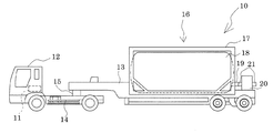
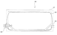
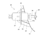
図1は本発明の一実施形態に係る液体移送用車両の概略構造を示す側面図であり、図2は液体タンクの概略を示す側面図であり、図3は撹拌装置部分の液体タンクの拡大断面図である。また、図4は、本発明の一実施形態に係る液体移送供給方法を示す概略図である。 FIG. 1 is a side view showing a schematic structure of a liquid transfer vehicle according to an embodiment of the present invention, FIG. 2 is a side view showing an outline of a liquid tank, and FIG. 3 is an enlarged view of the liquid tank in the stirring device portion. It is sectional drawing. FIG. 4 is a schematic view showing a liquid transfer supply method according to an embodiment of the present invention.
本実施形態に係る液体移送用車両は、複数種の液体を混合した混合液である化学薬品を移送するための車両である。なお、液体移送用車両によって移送する混合液は、勿論、化学薬品に限定されるものではない。 The liquid transfer vehicle according to the present embodiment is a vehicle for transferring a chemical that is a mixed liquid obtained by mixing a plurality of types of liquids. Of course, the liquid mixture transferred by the liquid transfer vehicle is not limited to chemicals.
図示するように、本実施形態に係る液体移送用車両10は、内燃機関であるエンジン11で走行するトラクタ12と、トレーラ13とで構成されている。トレーラ13は、トラクタ12の牽引部14に設けられた連結装置15を介してトラクタ12と着脱自在に連結されている。このトレーラ13の荷台には、液体タンクコンテナ16が載置固定されている。液体タンクコンテナ16はコンテナ本体17に液体タンク18を備えた構成となっている。なお、トラクタ12の牽引部14には、異なる種類のトレーラ13、すなわち、異なる種類の液体タンクコンテナ16が固定されたトレーラ13が接続可能となっている。
As shown in the figure, the
液体タンク18は、例えば、SUS316等によって形成され、その容量は20ton程度である。また液体タンク18の外壁には、トラクタ12の進行方向後方側に、液体タンク18内に液体を搬入あるいは液体タンク18内の液体を外部に排出するための液体タンク側配管19が設けられている。例えば、本実施形態では、液体タンク18内に液体を圧送、あるいは液体タンク18内の液体を外部に圧送するための圧送手段、例えば、ロータリーポンプ20がトレーラ13に搭載されており、このロータリーポンプ20が液体タンク側配管19に接続されている。具体的には、ロータリーポンプ20には流入側と吐出側のトレーラ側配管21が設けられており、これらトレーラ側配管21と液体タンク側配管19とが接続されている。つまり、ロータリーポンプ20の駆動により、2種類の液体が液体タンク18内に外部から圧送され、また液体タンク18内の液体(化学薬品)がトレーラ側配管21を介して外部、例えば、使用先の貯蔵タンク等に圧送される。なお、液体タンク18への液体の搬入は、液体タンク18上部に設けられる図示しないマンホールから行うようにしてもよいことは言うまでもない。また、ロータリーポンプ20はトラクタ12のエンジン11によって駆動されるようになっている。このため、専用の動力源を設けることなく、ロータリーポンプ20を駆動することができる。勿論、ロータリーポンプ20は、専用の駆動源によって駆動するようにしてもよい。
The
液体タンク18には、液体タンク18内に搬入された液体、例えば、本実施形態では、化学薬品の原料となる2種類の液体を撹拌する撹拌装置22が設けられている。この撹拌装置22は、本実施形態では、液体タンク18の外壁に固定されている。撹拌装置22の液体タンク18への固定位置は、特に限定されないが、液体タンク18の外壁の、トラクタ12の進行方向前方側の面であることが好ましい。このような位置に撹拌装置22を固定することで、撹拌装置22を、他の機器等に干渉することなく良好に固定することができる。さらに撹拌装置22は、液体タンク18の底面近傍に固定されていることが好ましい。比較的少量の液体が液体タンク18内に搬入されている場合でも、液体タンク18内の液体を確実に撹拌することができるからである。
The
例えば、本実施形態では、液体タンク18の外壁(側壁)に、略水平方向に突出する突出管23が設けられており、撹拌装置22は、この突出管23内に配されて突出管23の先端に設けられるフランジ部24に、ねじ等の締結部材(図示なし)によって固定されている。なお、突出管23の外周面には、複数、例えば、4つのリブ25が設けられて突出管23の強度が確保されている。このように撹拌装置22が内装される突出管23の内面の少なくとも下端部分23aは、液体タンク18側に向かって下るように傾斜していることが好ましい。これにより、突出管23内に液体が溜まってしまうのを防止することができる。
For example, in the present embodiment, the outer wall (side wall) of the
ここで、本実施形態に係る撹拌装置22は、液体タンク18内の液体を撹拌できるものであれば特に限定されないが、例えば、本実施形態では、図3に示すように、液体を撹拌するための撹拌翼であるインペラ26を有し、このインペラ26が電動モータ等の回転駆動手段27の回転軸28に固定されてなる。すなわち、本実施形態の撹拌装置22は、回転軸28に固定されたインペラ26を回転駆動手段27で回転させることによって、液体タンク18内の2種類の液体を撹拌する。そして、このように撹拌装置22で液体タンク18内の液体を撹拌することによって、複数種の液体の混合液である化学薬品となる。
Here, the stirring
なお、撹拌装置22の回転駆動手段27は、例えば、使用先から電力の供給を受けて駆動するようにすればよいが、勿論それ以外の方法で駆動させるようにしてもよい。例えば、トラクタ12のエンジン11を動力源として発電機を作動させ、この発電機から電力によって回転駆動手段27を駆動するようにしてもよい。また、撹拌装置22の動力源は、電動モータである回転駆動手段27に限定されず、例えば、ロータリーポンプ20と同様に、トラクタ12のエンジン11を動力源として利用するようにしてもよい。
The rotation driving means 27 of the stirring
そして、本実施形態の液体移送供給方法では、このような液体移送用車両10を用いて、化学薬品の原料となる複数種、本実施形態では2種類の液体を使用先(顧客先)まで移送すると共に、これら2種類の液体を最終的に化学薬品として使用先に供給する。具体的には、化学薬品の原料となる2種類の液体を、液体移送用車両10の液体タンク18に搬入して使用先まで搬送する。例えば、本実施形態では、図4に示すように、2種類の液体A及びBをそれぞれ製造する製造会社51,52で液体移送用車両10の一つの液体タンク18内に搬入し、使用先53まで移送している。なお、液体移送用車両10を使用先53まで移動させる際に液体タンク18に揺れは生じるものの、この揺れによって液体タンク18内の液体全体が完全に撹拌されることはない。
In the liquid transfer and supply method according to the present embodiment, such a
このように液体移送用車両10の一つの液体タンク18で2種類の液体を使用先53まで移送した後、使用先53で液体タンク18内の2種類の液体A,Bを撹拌(混合)する。すなわち、使用先53で、液体移送用車両10を停止した状態で撹拌装置22を作動させて液体タンク18内の2種類の液体A,Bを撹拌する。これにより、撹拌された液体A,Bが液体タンク18内で混合液である化学薬品Cとなり、得られた化学薬品Cを液体タンク18から使用先に供給する。すなわち、液体タンク18内の化学薬品Cをロータリーポンプ20によって使用先53の所定の貯蔵タンク54に圧送する。なお、複数種の液体の撹拌とは、所定の化学薬品に水を加えて濃度を下げる操作も含まれる。
As described above, after the two types of liquid are transferred to the
このように、本発明の液体移送供給方法では、液体移送用車両10に設けられた液体タンク18内に複数種の液体A,Bを搬入し、これら複数種の液体A,Bを液体移送用車両10によって使用先53まで移送し、液体タンク18に固定された撹拌装置22によって液体タンク18内で混合液である化学薬品Cとし、液体タンク18から所望の化学薬品Cを使用先53に供給するようにした。これにより、撹拌作業の作業効率が大幅に向上する。また、使用先に複数種の液体を貯蔵する複数の貯蔵タンクを設ける必要がなく、混合液である化学薬品用の貯蔵タンクだけを設置すれば済むため、設備を簡素化することもできるという効果もある。
As described above, in the liquid transfer supply method of the present invention, a plurality of types of liquids A and B are carried into the
以上本発明の一実施形態について説明したが、勿論、本発明は上述の実施形態に限定されるものではない。例えば、上述の実施形態では、混合液の一例として危険物である化学薬品を挙げたが、勿論、混合物は危険物以外の液体、例えば、飲料水、工業製品等であってもよい。また、上述の実施形態では、2種類の液体を混合した化学薬品を例示したが、勿論、撹拌する液体の種類は、3種類以上であってもよい。 Although one embodiment of the present invention has been described above, of course, the present invention is not limited to the above-described embodiment. For example, in the above-described embodiment, a chemical that is a dangerous substance is given as an example of the mixed liquid. However, the mixture may be a liquid other than the dangerous substance, for example, drinking water, an industrial product, or the like. Further, in the above-described embodiment, the chemical agent in which two kinds of liquids are mixed is illustrated, but of course, the kind of liquid to be stirred may be three or more kinds.
また、上述の実施形態では、使用先で液体移送用車両を停止した状態で液体を撹拌して混合物(化学薬品)としたが、例えば、液体移送用車両の移動中に液体タンク内で、複数種の液体を撹拌するようにしてもよい。ただし、車両の移動中における化学薬品等の危険物の製造は、消防法によって禁止されているため、実際には、混合物が非危険物である場合に限られる。 In the above-described embodiment, the liquid is agitated to obtain a mixture (chemical) while the liquid transfer vehicle is stopped at the use destination. For example, a plurality of liquid transfer vehicles are moved in the liquid tank while the liquid transfer vehicle is moving. The seed liquid may be stirred. However, since the production of dangerous substances such as chemicals during the movement of the vehicle is prohibited by the Fire Service Act, it is actually limited to the case where the mixture is non-dangerous.
また、上述の実施形態では、液体移送用車両としてトラクタにトレーラが連結されたものを例示したが、勿論、液体移送用車両の構造は特に限定されるものではない。 In the above-described embodiment, the liquid transfer vehicle is exemplified by a trailer connected to a tractor. However, the structure of the liquid transfer vehicle is not particularly limited.
10 液体移送用車両
11 エンジン
12 トラクタ
13 トレーラ
14 牽引部
15 連結装置
16 液体タンクコンテナ
17 コンテナ本体
18 液体タンク
19 液体タンク側配管
20 ロータリーポンプ
21 トレーラ側配管
22 撹拌装置
23 突出管
24 フランジ部
25 リブ
26 インペラ
27 回転駆動手段
28 回転軸
51,52 製造会社
53 使用先
54 貯蔵タンク
DESCRIPTION OF
Claims (9)
The liquid transfer vehicle according to any one of claims 4 to 8, wherein the stirring device is operated using power generated by a power source of the vehicle.
Priority Applications (1)
| Application Number | Priority Date | Filing Date | Title |
|---|---|---|---|
| JP2006198702A JP2008024145A (en) | 2006-07-20 | 2006-07-20 | Transfer and supply method of liquid and vehicle for transferring liquid |
Applications Claiming Priority (1)
| Application Number | Priority Date | Filing Date | Title |
|---|---|---|---|
| JP2006198702A JP2008024145A (en) | 2006-07-20 | 2006-07-20 | Transfer and supply method of liquid and vehicle for transferring liquid |
Publications (1)
| Publication Number | Publication Date |
|---|---|
| JP2008024145A true JP2008024145A (en) | 2008-02-07 |
Family
ID=39115229
Family Applications (1)
| Application Number | Title | Priority Date | Filing Date |
|---|---|---|---|
| JP2006198702A Pending JP2008024145A (en) | 2006-07-20 | 2006-07-20 | Transfer and supply method of liquid and vehicle for transferring liquid |
Country Status (1)
| Country | Link |
|---|---|
| JP (1) | JP2008024145A (en) |
Citations (3)
| Publication number | Priority date | Publication date | Assignee | Title |
|---|---|---|---|---|
| JPH01240498A (en) * | 1988-03-14 | 1989-09-26 | Sansou Kagaku Kk | Method of feeding mixture stored in tank lorry and apparatus therefor |
| JP2004041917A (en) * | 2002-07-11 | 2004-02-12 | Nippon Gurisutaa Service Kk | Ink transporting method and ink transporting vehicle |
| JP2006036318A (en) * | 2004-07-29 | 2006-02-09 | Shigefumi Morohoshi | Chemical transporting method |
-
2006
- 2006-07-20 JP JP2006198702A patent/JP2008024145A/en active Pending
Patent Citations (3)
| Publication number | Priority date | Publication date | Assignee | Title |
|---|---|---|---|---|
| JPH01240498A (en) * | 1988-03-14 | 1989-09-26 | Sansou Kagaku Kk | Method of feeding mixture stored in tank lorry and apparatus therefor |
| JP2004041917A (en) * | 2002-07-11 | 2004-02-12 | Nippon Gurisutaa Service Kk | Ink transporting method and ink transporting vehicle |
| JP2006036318A (en) * | 2004-07-29 | 2006-02-09 | Shigefumi Morohoshi | Chemical transporting method |
Similar Documents
| Publication | Publication Date | Title |
|---|---|---|
| US9259699B2 (en) | Mixing apparatus for transportation of refinery solids waste | |
| US5851068A (en) | Intermodal transportation of sedimentary substances | |
| US5275487A (en) | Hazardous waste transportation and disposal | |
| US8865006B2 (en) | Concrete washout separation system | |
| US6443613B1 (en) | Method for transporting and delivering substances | |
| US6276826B1 (en) | Apparatus for transporting and delivering substances | |
| US6964511B2 (en) | Mixing apparatus and method | |
| JP2008024145A (en) | Transfer and supply method of liquid and vehicle for transferring liquid | |
| US6851845B2 (en) | Method and apparatus for processing waste material | |
| US5626423A (en) | Apparatus and method for transporting and agitating a substance | |
| JP5032256B2 (en) | Soil improvement machine | |
| JP2009040485A (en) | Granular powder-housing tank container | |
| JP4471773B2 (en) | Multi-function mixing device, foaming device, light-weight solidified material manufacturing method, light-weight solidified body | |
| CN215624159U (en) | Tank truck, tank container and stirring device thereof | |
| JP3922377B2 (en) | How to transport chemicals | |
| JP6317613B2 (en) | Method and system for manufacturing and backfilling fluidized soil | |
| CN201082571Y (en) | Mechanic operating type concrete premixing device | |
| RU2235018C1 (en) | Mixing plant for preparation of solutions | |
| US6332708B1 (en) | Method of shipping manganese dioxide | |
| JP2006036318A (en) | Chemical transporting method | |
| US3479015A (en) | Fluid blending apparatus |
Legal Events
| Date | Code | Title | Description |
|---|---|---|---|
| A977 | Report on retrieval |
Free format text: JAPANESE INTERMEDIATE CODE: A971007 Effective date: 20100203 |
|
| A131 | Notification of reasons for refusal |
Free format text: JAPANESE INTERMEDIATE CODE: A131 Effective date: 20100303 |
|
| A02 | Decision of refusal |
Free format text: JAPANESE INTERMEDIATE CODE: A02 Effective date: 20100630 |