JP2008018491A - Side cutter - Google Patents
Side cutter Download PDFInfo
- Publication number
- JP2008018491A JP2008018491A JP2006191551A JP2006191551A JP2008018491A JP 2008018491 A JP2008018491 A JP 2008018491A JP 2006191551 A JP2006191551 A JP 2006191551A JP 2006191551 A JP2006191551 A JP 2006191551A JP 2008018491 A JP2008018491 A JP 2008018491A
- Authority
- JP
- Japan
- Prior art keywords
- outer peripheral
- side cutter
- shape
- blade
- cutter
- Prior art date
- Legal status (The legal status is an assumption and is not a legal conclusion. Google has not performed a legal analysis and makes no representation as to the accuracy of the status listed.)
- Pending
Links
Images


Abstract
Description
本発明は、サイドカッタに関し、特に被削材に溝を加工したり切断したりするためのサイドカッタに関するものである。 The present invention relates to a side cutter, and more particularly to a side cutter for machining or cutting a groove in a work material.
従来より、この種のサイドカッタとして、大径円板の工具本体の外周に、前記工具本体の一の基準端面に対して正のアキシャルレーキ角を付された複数のスローアウェイチップと、負のアキシャルレーキ角を付された複数のスローアウェイチップとが円周方向に交互にかつ等間隔を隔てて装着されたものが知られている。さらに、一部の前記スローアウェイチップのラジアルレーキ角を、その他のスローアウェイチップのラジアルレーキ角と異なる角度に設定したものがあった(例えば、特許文献1参照)。
しかしながら、特許文献1に記載されたサイドカッタでは、工具本体の周方向に交互にかつ等間隔を隔てて装着されているため、該サイドカッタの幅方向に作用する切削抵抗がアンバランスになるため、溝加工中にびびり振動が発生し最悪の場合チップのコーナ部が欠損する問題があった。
また、スローアウェイチップが負のアキシャルレーキ角−θ1とされているため、切屑が長く伸びた場合には、加工溝の両壁面に擦過し表面粗さを悪化させたり、切屑を排出できなくなったりするおそれがあった。
However, since the side cutter described in
In addition, since the throw-away tip has a negative axial rake angle −θ1, if the chips extend for a long time, they may rub against both wall surfaces of the processing groove to deteriorate the surface roughness, or the chips cannot be discharged. There was a risk.
本発明は、上述の問題を解決するためになされたもので、切削バランスに優れるとともに、切屑の排出性能に優れたサイドカッタを提供することを目的とする。 The present invention has been made to solve the above-described problems, and an object thereof is to provide a side cutter that is excellent in cutting balance and excellent in chip discharging performance.
上述した課題を解決するために、請求項1記載の発明は、略円盤状をなし、その軸線まわりに回転させられる工具本体の外周面から突出する、複数の外周刃を備えてなるサイドカッタにおいて、前記外周刃を、該サイドカッタを幅方向で2等分する平面に対して対称的に形成したことを特徴とする。
請求項1記載のサイドカッタによれば、外周刃を、サイドカッタを幅方向で2等分する平面に対して対称的に形成したことから、切削中の切削バランスに優れ、びびり及びこのびびりに起因する外周刃の欠損が発生することを防止する。
In order to solve the above-mentioned problem, the invention according to
According to the side cutter of
請求項2に係る発明は、請求項1記載の発明において、前記外周刃を工具回転方向に向かって凸の山形形状、凹の谷形形状、凸曲線状又は凹曲線状のいずれかとしたことを特徴とする。
請求項2記載の発明によれば、外周刃を工具回転方向に凸の山形形状、凹の谷形形状、凸曲線状又は凹曲線状のいずれかとしたことから、該外周刃の被削材への食付きを良好にするとともに、該サイドカッタが幅方向に振られることを防止する。さらに、前記山形形状又は谷形形状に倣って切屑を生成するため、左右に振られることがなく溝の両壁面に擦過することを防止する。
The invention according to
According to the second aspect of the present invention, since the outer peripheral edge is any one of a convex chevron shape, a concave valley shape, a convex curve shape, or a concave curve shape in the tool rotation direction, As a result, the side cutter is prevented from being shaken in the width direction. Furthermore, since the chips are generated following the chevron shape or the valley shape, it is prevented from rubbing on both wall surfaces of the groove without being swung left and right.
請求項3記載の発明は、請求項1又は2記載の発明において、前記工具本体の両端面側に位置する外周刃と交差する側刃に、前記軸線に略直交する直線状または曲線状をなす副切刃を備えたことを特徴とする。
請求項3記載の発明によれば、加工溝の壁面を切削する側刃に、該サイドカッタの軸線に略直交する副切刃を備えたことから、前記壁面の表面粗さ及び寸法精度をさらに良好とする。
According to a third aspect of the present invention, in the first or second aspect of the present invention, the side blade intersecting with the outer peripheral blade located on the both end surfaces of the tool body has a linear shape or a curved shape substantially orthogonal to the axis. A secondary cutting edge is provided.
According to the third aspect of the present invention, the side blade that cuts the wall surface of the machining groove is provided with the sub-cutting blade substantially orthogonal to the axis of the side cutter, so that the surface roughness and dimensional accuracy of the wall surface are further increased. Good.
本発明のサイドカッタは、上述したように切削中の切削バランスに優れ、びびり及びこのびびりに起因する外周刃の欠損が発生することを防止するといった効果を奏する。 The side cutter of the present invention is excellent in the cutting balance during cutting as described above, and has an effect of preventing the occurrence of chatter and the loss of the outer peripheral edge due to the chatter.
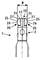
以下に、本発明の第1の実施形態に係るサイドカッタについて、図1〜図3を参照しながら説明する。図1は本サイドカッタの一部正面図である。図2は同サイドカッタの一部平面図である。図3は同サイドカッタの一部縦断面図である。 Below, the side cutter which concerns on the 1st Embodiment of this invention is demonstrated, referring FIGS. 1-3. FIG. 1 is a partial front view of the side cutter. FIG. 2 is a partial plan view of the side cutter. FIG. 3 is a partial longitudinal sectional view of the side cutter.
図1〜図3に図示するように本実施形態に係るサイドカッタ1は、略円盤状をなし、その軸線まわりに回転させられる工具本体2の外周面に、外周刃11、21を備えた複数のチップ10、20が取付け穴を介して締付ねじ4によって着脱可能に装着されている。チップ10、20は、超硬合金、サーメット、セラミックス等の硬質材料から適宜選択される。チップ10、20は、工具本体2の両端面側に配置された端面側チップ20と、工具本体2の幅方向の中央部に配置された中間チップ10とから構成されている。これら端面側チップ20及び中間チップ10は、略矩形板状をなしその一側面を工具回転方向Kに面するすくい面12、22とされ、このすくい面12、22の一辺稜部には、工具本体2の外周面から突出する外周刃11、21が形成されている。互いに隣り合う中間チップ10および各端面側チップ20は、各々の外周刃11、21の軸線まわりの回転軌跡が一部オーバーラップし、該サイドカッタ1の刃幅Wにわたって連続するように配置されている。各端面側チップ20においては、外周刃21と円弧状のコーナ27を挟んで交差する辺稜部に、工具本体2の端面から突出する側刃24が形成されている。
As shown in FIGS. 1 to 3, the
各端面側チップ20および中間刃チップ10は、工具本体2に直接または図1および図2に図示するようにカートリッジ30を介して装着される。カートリッジ30は、工具本体2の外周面に設けられたカートリッジ取付け溝3に挿入され、該カートリッジ30の取付け穴を介して工具本体2に螺合する締付ボルト6および該カートリッジ30の工具回転方向K側に設けられた楔部材40の少なくとも一方によって固定されている。さらに、各カートリッジ30の工具回転方向K背面側を向く側面には該サイドカッタ1の径方向に延びる凸部が設けられ、対応するカートリッジ取付け溝3の工具回転方向K前方側を向く壁面には前記凸部に係合する凹部が設けられており、前記凸部と凹部とが係合することによって、各カートリッジ30は、該サイドカッタ1の幅方向に位置決めされるとともに移動を阻止される。
Each end
図2からわかるように各端面側チップ20および中間チップ10の外周刃11、21は、該サイドカッタ1を幅方向で2等分する平面に対して対称的に形成されているため、該サイドカッタ1は、被削材に溝加工する際において、切削バランスに優れ幅方向に振られることがなくなるためびびり及びこのびびりに起因する外周刃の欠損を防止できる。
As can be seen from FIG. 2, each of the end
さらに、中間チップ10に備わる外周刃11は、該サイドカッタ1を幅方向で2等分する平面に対して対称かつ工具回転方向K前方側に向かって凸であって直線で構成された山形形状とされている。そのため、前記山形形状の最先端から両端側へと徐々に被削材に食付くため被削材への食付きが良好になるとともに、該サイドカッタ1が幅方向に振られることを防止できる。さらに、前記山形形状に倣って生成する切屑においても前記幅方向に振られることがなく加工溝の両壁面に擦過して傷付けることを回避できる。なお、中間チップ10に備わる外周刃11を、該サイドカッタ1を幅方向で2等分する平面に対して対称かつ工具回転方向に対して凹であって直線で構成された谷形形状とした場合にも、外周刃11の両端部から中央の谷底へと徐々に被削材に食付くため被削材への食付きが良好になるとともに、該サイドカッタ1が幅方向に振られることを防止できる。さらに、前記谷形形状に倣って生成する切屑においても前記幅方向に振られることがなく加工溝の両壁面に擦過して傷付けることを回避できる。
Further, the outer
さらに、工具本体2の一端面および他端面側に互いに対称的に装着された各端面側チップ20に備わる外周刃21は、該サイドカッタ1の幅方向で、その端部から中央側へ向かうにつれ、工具回転方向K背面側へ向かうように軸線に対して傾斜していることから、前記端部から中央側へと徐々に被削材に食付くため被削材への食付きが良好になるとともに、各外周刃21が同時に被削材に食付くため、該サイドカッタ1が幅方向に振られることを防止できる。さらに、該外周刃21から生成する切屑が加工溝の壁面から離れる方向に流れるため、加工溝の壁面に擦過して傷付けることを回避できる。
Further, the outer
さらに、各両端面側チップ20の側刃24には、軸線に略直交する直線状または曲線状をなす副切刃25が設けられてもよい。このような副切刃25を設けた場合には、加工溝の両壁面が平滑化されるため、両壁面の表面粗さおよび寸法精度が大幅に向上する。なお、副切刃25を備えた端面側チップ20は、工具本体2の各端面側に少なくとも1個装着されていればよい。
Furthermore, the
本サイドカッタ1では、刃幅Wにわたって配置された外周刃が該サイドカッタ1を幅方向で2等分する平面に対して対称的な形状となっていれば、前記中間チップ10のみを用いた態様、または、前記端面側チップ20のみを用いた態様としてもよい。
In the
本実施形態に係るサイドカッタにおける中間チップに備わる外周刃の変形例を図4および図5に示す。図4および図5は前記変形例の一部平面図である。これに図示するように本変形例は、中間チップ10に備わる外周刃11を凸曲線状、凹曲線状としたものであり、このような態様として場合においても、被削材への食付き性の向上、切屑排出性の向上といった効果を奏する。
4 and 5 show a modification of the outer peripheral blade provided in the intermediate tip in the side cutter according to the present embodiment. 4 and 5 are partial plan views of the modified example. As shown in the drawing, in this modification, the outer
次に、他の第2の実施形態に係るサイドカッタについて図6〜図8を参照しながら説明する。図6は本実施形態に係るサイドカッタの一部正面図である。図7は同サイドカッタの一部平面図である。図8は同サイドカッタの一部縦断面図である。図6〜図8において、第1の実施形態と同一の構成には同一符号を付し、その説明は省略する。 Next, a side cutter according to another second embodiment will be described with reference to FIGS. FIG. 6 is a partial front view of the side cutter according to the present embodiment. FIG. 7 is a partial plan view of the side cutter. FIG. 8 is a partial longitudinal sectional view of the side cutter. 6 to 8, the same components as those of the first embodiment are denoted by the same reference numerals, and the description thereof is omitted.
本サイドカッタ1は、図7からわかるように該サイドカッタ1の幅方向で2つの中間チップ10を並列かつ隣接させることによって、第1の実施形態にくらべ幅広の溝加工に好適するものである。各中間チップ10に備わる外周刃11は、第1の実施形態と同様に、工具回転方向Kに向かって凸の山形形状とされ、該サイドカッタ1の幅方向を2等分する平面に対して略対称的に形成されている。端面側チップ20の構成は、第1の実施形態とほぼ同様である。
As can be seen from FIG. 7, the
以上の構成を有するサイドカッタ1は、第1の実施形態で述べた効果に加えて、並列かつ隣接した1組の中間刃チップ10から生成する各切屑の幅を加工溝の幅に比較して小さくすることができ、しかも各中間チップから生成する切屑同士が絡み合うことを防止するため、切屑排出性能が悪化することを防止する。
In addition to the effects described in the first embodiment, the
なお、並列かつ隣接した1組の中間チップ10は、互いに密着するか、わずかに隙間をあけて配置されるが、これら中間チップ10に備わる各外周刃11を互いにオーバーラップさせることができないことから、外周刃11が欠如した領域が存在する。したがって、前記外周刃11が欠如した領域をなくすため、図7および図8からわかるように周方向で間隔をあけた2組の中間チップ10を、幅方向に相対的にWrだけずらして配置することが望ましい。このようにした場合、各組の中間チップ10に存在する、外周刃11が欠如した領域を互いに補い合うことができる。なお、各組の中間チップ10で形成される外周刃11は、該サイドカッタ1の幅方向を2等分する平面に対する完全な対称とはならないが、1組の中間刃で形成された外周刃11全体の長さに対してずらし量Wrが非常に小さく抑えられていれば、切削バランスに与える悪影響はほとんどない。
A pair of
1 サイドカッタ
2 工具本体
10 中間チップ
20 端面側チップ
11、21 外周刃
12、22 すくい面
13、23 外周逃げ面
24 側刃
25 副切刃
26 側逃げ面
27 コーナ
DESCRIPTION OF
Claims (3)
前記外周刃を、該サイドカッタを幅方向で2等分する平面に対して略対称的に形成したことを特徴とするサイドカッタ。 In a side cutter comprising a plurality of outer peripheral blades that form a substantially disk shape and project from the outer peripheral surface of the tool body that is rotated around its axis,
A side cutter characterized in that the outer peripheral blade is formed substantially symmetrically with respect to a plane that bisects the side cutter in the width direction.
The side blade intersecting with the outer peripheral blade located on both end faces of the tool body is provided with a secondary cutting blade having a linear shape or a curved shape substantially orthogonal to the axis. Side cutter.
Priority Applications (1)
| Application Number | Priority Date | Filing Date | Title |
|---|---|---|---|
| JP2006191551A JP2008018491A (en) | 2006-07-12 | 2006-07-12 | Side cutter |
Applications Claiming Priority (1)
| Application Number | Priority Date | Filing Date | Title |
|---|---|---|---|
| JP2006191551A JP2008018491A (en) | 2006-07-12 | 2006-07-12 | Side cutter |
Publications (1)
| Publication Number | Publication Date |
|---|---|
| JP2008018491A true JP2008018491A (en) | 2008-01-31 |
Family
ID=39074850
Family Applications (1)
| Application Number | Title | Priority Date | Filing Date |
|---|---|---|---|
| JP2006191551A Pending JP2008018491A (en) | 2006-07-12 | 2006-07-12 | Side cutter |
Country Status (1)
| Country | Link |
|---|---|
| JP (1) | JP2008018491A (en) |
Cited By (4)
| Publication number | Priority date | Publication date | Assignee | Title |
|---|---|---|---|---|
| CN103769663A (en) * | 2014-02-12 | 2014-05-07 | 哈尔滨理工大学 | Special cutting-width-variable three-edge milling cutter for grooving overall blade disk |
| CN106180845A (en) * | 2016-08-16 | 2016-12-07 | 上海哈申工具有限公司 | Throw away scrapes slotting cutter device and the processing method thereof of light knife structure |
| WO2022243406A1 (en) * | 2021-05-19 | 2022-11-24 | Element Six (Uk) Limited | Disc cutter |
| WO2022243402A1 (en) * | 2021-05-19 | 2022-11-24 | Element Six (Uk) Limited | Disc cutter |
Citations (6)
| Publication number | Priority date | Publication date | Assignee | Title |
|---|---|---|---|---|
| JPS6056420U (en) * | 1983-09-26 | 1985-04-19 | 東芝タンガロイ株式会社 | Throw-away cutter for cutting grooves |
| JPS60157120U (en) * | 1984-03-28 | 1985-10-19 | 三菱マテリアル株式会社 | Polygonal throw-away tip |
| JPH0871829A (en) * | 1994-09-07 | 1996-03-19 | Barta Ag | Method and milling cutter tool for forming deep groove |
| JPH11197934A (en) * | 1998-01-16 | 1999-07-27 | Mitsubishi Materials Corp | Throw-away tip and ball end mill |
| JP2002263918A (en) * | 2001-03-06 | 2002-09-17 | Osg Corp | Throw-away tip and milling tool on which the throw-away tip is installed |
| JP2004515373A (en) * | 2000-12-05 | 2004-05-27 | イスカーリミテッド | Rotary cutting tool |
-
2006
- 2006-07-12 JP JP2006191551A patent/JP2008018491A/en active Pending
Patent Citations (6)
| Publication number | Priority date | Publication date | Assignee | Title |
|---|---|---|---|---|
| JPS6056420U (en) * | 1983-09-26 | 1985-04-19 | 東芝タンガロイ株式会社 | Throw-away cutter for cutting grooves |
| JPS60157120U (en) * | 1984-03-28 | 1985-10-19 | 三菱マテリアル株式会社 | Polygonal throw-away tip |
| JPH0871829A (en) * | 1994-09-07 | 1996-03-19 | Barta Ag | Method and milling cutter tool for forming deep groove |
| JPH11197934A (en) * | 1998-01-16 | 1999-07-27 | Mitsubishi Materials Corp | Throw-away tip and ball end mill |
| JP2004515373A (en) * | 2000-12-05 | 2004-05-27 | イスカーリミテッド | Rotary cutting tool |
| JP2002263918A (en) * | 2001-03-06 | 2002-09-17 | Osg Corp | Throw-away tip and milling tool on which the throw-away tip is installed |
Cited By (6)
| Publication number | Priority date | Publication date | Assignee | Title |
|---|---|---|---|---|
| CN103769663A (en) * | 2014-02-12 | 2014-05-07 | 哈尔滨理工大学 | Special cutting-width-variable three-edge milling cutter for grooving overall blade disk |
| CN103769663B (en) * | 2014-02-12 | 2016-04-13 | 哈尔滨理工大学 | Wide face and side cutter is cut in blisk special change of slotting |
| CN106180845A (en) * | 2016-08-16 | 2016-12-07 | 上海哈申工具有限公司 | Throw away scrapes slotting cutter device and the processing method thereof of light knife structure |
| WO2022243406A1 (en) * | 2021-05-19 | 2022-11-24 | Element Six (Uk) Limited | Disc cutter |
| WO2022243402A1 (en) * | 2021-05-19 | 2022-11-24 | Element Six (Uk) Limited | Disc cutter |
| GB2609280B (en) * | 2021-05-19 | 2023-09-13 | Element Six Uk Ltd | Disc cutter |
Similar Documents
| Publication | Publication Date | Title |
|---|---|---|
| JP6580572B2 (en) | Indexable double-sided cutting insert and cutting tool therefor | |
| JP6532940B2 (en) | Double-sided cutting inserts and milling tools | |
| JP5681185B2 (en) | Cutting inserts and rotary cutting tools | |
| JP5451612B2 (en) | Cutting tool and cutting insert therefor | |
| WO2011046121A1 (en) | Cutting insert and rotary tool with a replaceable blade edge | |
| JPWO2007142224A1 (en) | Cutting tools and cutting inserts | |
| JP2017124464A (en) | Cutting insert and tip exchange type cutting tool | |
| JP6361948B2 (en) | Cutting inserts and cutting tools | |
| JPH05116019A (en) | Throw-away tip | |
| JP4803510B2 (en) | Insert and side cutter | |
| JP2008018491A (en) | Side cutter | |
| JPWO2010027055A1 (en) | Side cutter | |
| JP2005028502A (en) | Chamfering cutter, and throwaway tip for chamfering cutter | |
| WO2015137508A1 (en) | Cutting insert, tool body, and cutting tool | |
| WO2014034056A1 (en) | Cutting inserts and cutting tools using same | |
| JP2015196203A (en) | Edge replaceable metal saw | |
| JP4859815B2 (en) | Throw-away insert and turning tool with it | |
| JP2007237302A (en) | Cutter of crank pin miller | |
| JP4364173B2 (en) | Throw-away insert and turning tool with it | |
| JP2006263841A (en) | Axial feed knife edge replacement type tool | |
| JP2006205298A (en) | Cutting insert, milling cutter tool and cutting method using this cutting insert | |
| JP6014427B2 (en) | Cutting insert and cutting tool using the same | |
| JP2005066780A (en) | Throwaway type gear cutter | |
| JP2017113865A (en) | Chamfering tool | |
| JP2006224278A (en) | Insert for milling cutter |
Legal Events
| Date | Code | Title | Description |
|---|---|---|---|
| A621 | Written request for application examination |
Free format text: JAPANESE INTERMEDIATE CODE: A621 Effective date: 20090520 |
|
| A977 | Report on retrieval |
Free format text: JAPANESE INTERMEDIATE CODE: A971007 Effective date: 20111006 |
|
| A131 | Notification of reasons for refusal |
Effective date: 20111018 Free format text: JAPANESE INTERMEDIATE CODE: A131 |
|
| A521 | Written amendment |
Effective date: 20111216 Free format text: JAPANESE INTERMEDIATE CODE: A523 |
|
| A02 | Decision of refusal |
Free format text: JAPANESE INTERMEDIATE CODE: A02 Effective date: 20120515 |