JP2008009872A - Machine control device - Google Patents
Machine control device Download PDFInfo
- Publication number
- JP2008009872A JP2008009872A JP2006181722A JP2006181722A JP2008009872A JP 2008009872 A JP2008009872 A JP 2008009872A JP 2006181722 A JP2006181722 A JP 2006181722A JP 2006181722 A JP2006181722 A JP 2006181722A JP 2008009872 A JP2008009872 A JP 2008009872A
- Authority
- JP
- Japan
- Prior art keywords
- data
- communication
- cpu
- emergency stop
- communication data
- Prior art date
- Legal status (The legal status is an assumption and is not a legal conclusion. Google has not performed a legal analysis and makes no representation as to the accuracy of the status listed.)
- Granted
Links
- 238000004891 communication Methods 0.000 claims abstract description 382
- 238000001514 detection method Methods 0.000 claims abstract description 106
- 238000012544 monitoring process Methods 0.000 claims abstract description 99
- 238000004458 analytical method Methods 0.000 claims abstract description 6
- 230000005540 biological transmission Effects 0.000 claims description 201
- 230000005856 abnormality Effects 0.000 claims description 118
- 238000000034 method Methods 0.000 claims description 40
- 230000002159 abnormal effect Effects 0.000 claims description 33
- 238000007405 data analysis Methods 0.000 claims description 18
- 230000000903 blocking effect Effects 0.000 claims description 10
- 230000000737 periodic effect Effects 0.000 claims description 9
- 230000001771 impaired effect Effects 0.000 abstract description 3
- 230000004044 response Effects 0.000 description 55
- 238000012545 processing Methods 0.000 description 52
- 230000008569 process Effects 0.000 description 30
- 238000012790 confirmation Methods 0.000 description 18
- 230000000694 effects Effects 0.000 description 5
- 238000004364 calculation method Methods 0.000 description 4
- 238000010586 diagram Methods 0.000 description 4
- 238000012546 transfer Methods 0.000 description 3
- 238000009825 accumulation Methods 0.000 description 2
- 239000000284 extract Substances 0.000 description 2
- 238000012986 modification Methods 0.000 description 2
- 230000004048 modification Effects 0.000 description 2
- 230000003287 optical effect Effects 0.000 description 2
- 238000003466 welding Methods 0.000 description 2
- CDFKCKUONRRKJD-UHFFFAOYSA-N 1-(3-chlorophenoxy)-3-[2-[[3-(3-chlorophenoxy)-2-hydroxypropyl]amino]ethylamino]propan-2-ol;methanesulfonic acid Chemical compound CS(O)(=O)=O.CS(O)(=O)=O.C=1C=CC(Cl)=CC=1OCC(O)CNCCNCC(O)COC1=CC=CC(Cl)=C1 CDFKCKUONRRKJD-UHFFFAOYSA-N 0.000 description 1
- 230000008859 change Effects 0.000 description 1
- 238000006243 chemical reaction Methods 0.000 description 1
- 125000004122 cyclic group Chemical group 0.000 description 1
- 238000005516 engineering process Methods 0.000 description 1
- 238000012806 monitoring device Methods 0.000 description 1
- 238000003825 pressing Methods 0.000 description 1
- 230000007704 transition Effects 0.000 description 1
Images


Landscapes
- Numerical Control (AREA)
- Manipulator (AREA)
- Control Of Electric Motors In General (AREA)
Abstract
【課題】可搬式操作部と機械の制御を行う制御部間の通信を非有線で行う際、単一の故障で機械の非常停止動作の安全機能が損なわれることのないように多重化されたハードウエア回路と最小限の通信回路を有しながら信頼性を確保した通信プロトコルによって信頼性の高い非常停止通信を行うことができる機械制御装置を提供する。
【解決手段】ロボット制御装置30は、制御部20における第3CPU22、第4CPU23のそれぞれが、通信データに含まれるモニタ結果及び予め定められた通信プロトコルに従って作成された通信エラー検出データを解析する。そして、第3CPU22、第4CPU23がモニタ結果及び通信エラー検出データの解析結果に応じて第1電磁接触器制御回路26、第2電磁接触器制御回路27にOFFの制御信号を出力することにより、モニタ結果や通信エラーの内容に応じてロボットのモータM41への電力が遮断される。
【選択図】図1Multiplexing is performed so that a safety function of an emergency stop operation of a machine is not impaired by a single failure when communication between a portable operation unit and a control unit that controls the machine is performed in a non-wired manner. Provided is a machine control device capable of performing emergency stop communication with high reliability by a communication protocol having a hardware circuit and a minimum communication circuit while ensuring reliability.
In a robot control device, a third CPU and a fourth CPU in a control unit each analyze a monitoring result included in communication data and communication error detection data created according to a predetermined communication protocol. Then, the third CPU 22 and the fourth CPU 23 output an OFF control signal to the first electromagnetic contactor control circuit 26 and the second electromagnetic contactor control circuit 27 according to the monitoring result and the analysis result of the communication error detection data. The power to the motor M41 of the robot is cut off according to the result and the content of the communication error.
[Selection] Figure 1
Description
本発明は、機械を制御する機械制御装置に関し、詳しくは機械を非常停止させるための非常停止操作手段を備えた可搬式の操作盤との間を無線等による通信で結ばれた機械制御装置に関する。 The present invention relates to a machine control device that controls a machine, and more particularly to a machine control device that is connected to a portable operation panel provided with an emergency stop operation means for making an emergency stop of a machine by wireless communication or the like. .
従来、ロボット制御装置はロボットの動力を遮断するための非常停止スイッチを備えた可搬式の操作盤(例えば、ティーチペンダント)とケーブルで接続されていた。これに対して、特許文献1ではロボット制御装置とティーチペンダント間のデータの交信を電波や赤外線等の伝達媒体を使用して行う通信システムが開示されている。該通信システムではロボット制御装置とティーチペンダントは、それぞれ送信部と受信部が設けられるとともに、ティーチペンダントの受信部と送信部は、通常時にはロボット制御装置からのデータの受信とそれに対応する応答として所要のデータの返送をそれぞれ実行し、異常時にはこの該応答を停止するようにされている。 Conventionally, the robot control device is connected to a portable operation panel (for example, a teach pendant) having an emergency stop switch for cutting off the power of the robot with a cable. On the other hand, Patent Document 1 discloses a communication system that performs communication of data between a robot control device and a teach pendant using a transmission medium such as radio waves or infrared rays. In the communication system, the robot control device and the teach pendant are each provided with a transmission unit and a reception unit, and the reception unit and the transmission unit of the teach pendant are normally required for receiving data from the robot control device and corresponding responses. The data is returned, and the response is stopped when an abnormality occurs.
この技術ではロボット制御装置がティーチペンダントからの応答が無いことにより異常の発生が検知されてロボットを非常停止させることができるとともに、ティーチペンダントの故障が起きた時にも、応答が途絶えることによりフェイルセーフ機能を確保している。 With this technology, the robot controller can detect the occurrence of an abnormality due to the absence of a response from the teach pendant, so that the robot can be stopped urgently. The function is secured.
又、特許文献2のロボット制御装置では、ティーチペンダントには非常停止操作手段が操作されると非常停止指令を生成する複数の生成回路と、各生成回路に対応してロボット制御装置に無線で送信する複数の送信手段とが設けられ、ロボット制御装置には前記非常停止指令を受信する複数の受信手段が設けるられている。この構成によって、ロボットを停止させる回路の故障でロボットが停止しなくなるような事態を解消して信頼性を向上することが提案されている。
しかし、特許文献1の技術では、ロボットを停止させるための回路(例えば、非常停止スイッチ)が1つしか設けられておらず、無線が途絶えたときの安全は考慮されているが、ロボットを停止させるための回路が故障した場合の安全対策が考慮されていない。又、特許文献2では、様々な回路部分を多重化することにより、安全性が考慮されているが、例えば、送信回路や受信回路を多重化して設ける等、多重化の部分が多く、コスト的な問題、消費電力が大きくなる問題、操作盤が重くなる問題がある。
However, in the technique of Patent Document 1, only one circuit (for example, an emergency stop switch) for stopping the robot is provided, and safety when the radio is interrupted is considered, but the robot is stopped. Safety measures in case of failure of the circuit to cause the failure are not considered. In
本発明の目的は可搬式操作部と機械の制御を行う制御部間の通信を非有線で行う際、単一の故障で機械の非常停止動作の安全機能が損なわれることのないように多重化されたハードウエア回路と最小限の通信回路を有しながら信頼性を確保した通信プロトコルによって信頼性の高い非常停止通信を行うことができる機械制御装置を提供することにある。 The purpose of the present invention is to multiplex so that the safety function of the emergency stop operation of the machine is not impaired by a single failure when the communication between the portable operation unit and the control unit that controls the machine is performed in a non-wired manner. It is an object of the present invention to provide a machine control device capable of performing highly reliable emergency stop communication using a communication protocol that ensures reliability while having a hardware circuit and a minimum communication circuit.
上記問題点を解決するために、請求項1に記載の発明は、可搬式操作部と機械の制御を行う制御部とが非有線通信を行うようにした機械制御装置において、前記可搬式操作部は、多重化された接点を有する非常停止操作手段と、前記接点毎に設けられて該非常停止操作手段の動作をモニタし、そのモニタ結果及び通信エラー検出データを含む通信データを予め定められた通信プロトコルに従って作成する多重化されたモニタ手段と、前記通信データを非有線で通信する単一の第1通信手段とを備え、前記制御部は、前記第1通信手段と非有線で通信する単一の第2通信手段と、機械の駆動源への電力を遮断する多重化された遮断手段と、該遮断手段毎に設けられ、非常停止信号の入力に基づいて該遮断手段を制御する多重化された遮断制御手段と、前記遮断制御手段毎に設けられ、前記第2通信手段が受信した通信データのモニタ結果、及び通信エラー検出データの解析結果に応じて該遮断制御手段に前記非常停止信号を出力する多重化された通信データ解析手段とを備えたことを特徴とする機械制御装置を要旨とするものである。 In order to solve the above problem, the invention according to claim 1 is the machine control device in which the portable operation unit and the control unit for controlling the machine perform non-wired communication, the portable operation unit. Is provided with an emergency stop operation means having multiplexed contacts, and the operation of the emergency stop operation means provided for each contact is monitored, and communication data including the monitoring result and communication error detection data is predetermined. Multiplexed monitor means created in accordance with a communication protocol and a single first communication means for communicating the communication data in a non-wired manner, the control unit communicating with the first communication means in a non-wired manner. A second communication means, a multiplexed shut-off means for shutting off the power to the drive source of the machine, and a multiplexing provided for each shut-off means and controlling the shut-off means based on the input of an emergency stop signal Shut-off control hand And a multiplexing unit that is provided for each cutoff control unit and outputs the emergency stop signal to the cutoff control unit according to the monitoring result of the communication data received by the second communication unit and the analysis result of the communication error detection data. The gist of the machine control device is provided with the communication data analyzing means.
なお、非有線通信とは、無線通信(通信媒体:電波)、赤外線通信、光通信、或いは磁気通信を含み、いずれもワイヤレスで行う伝送方式のことをいう。又、多重化とは、2重化以上を含む趣旨である。 Note that the non-wired communication refers to a transmission method that includes wireless communication (communication medium: radio wave), infrared communication, optical communication, or magnetic communication, all of which are performed wirelessly. Multiplexing is intended to include duplexing or more.
請求項2の発明は、請求項1において、前記通信データは、通信エラー検出データとして宛先データ及び送信元データを含む通信パケットにて構成され、前記各通信データ解析手段は、該通信データに含まれる宛先データ及び送信元データに基づいて前記通信データの同定を行い、同定ができなかった場合には、通信データの同定不能による通信エラーとして次回の受信を待つことを特徴とする。 According to a second aspect of the present invention, in the first aspect, the communication data includes a communication packet including destination data and transmission source data as communication error detection data, and each of the communication data analyzing means is included in the communication data. The communication data is identified based on the destination data and the transmission source data. If the communication data cannot be identified, the next reception is awaited as a communication error due to the inability to identify the communication data.
請求項3の発明は、請求項1又は請求項2において、前記通信データは、通信エラー検出データとして該通信データが作成される毎に更新される通信番号データを含む通信パケットにて構成され、前記各通信データ解析手段は、該通信番号データに基づく通信エラーの場合には、前記遮断制御手段を制御して前記遮断手段を遮断動作させることを特徴とする。
The invention of
請求項4の発明は、請求項1乃至請求項3のうちいずれか1項において、前記通信データは、通信エラー検出データとして誤り検出データを含む通信パケットにて構成され、前記各通信データ解析手段は、該誤り検出データに基づいて、該通信データがデータ異常か否かを判定し、データ異常の場合には、前記遮断制御手段を制御して前記遮断手段を遮断動作させることを特徴とする。 According to a fourth aspect of the present invention, in any one of the first to third aspects, the communication data includes a communication packet including error detection data as communication error detection data. Based on the error detection data, it is determined whether or not the communication data is abnormal. If the data is abnormal, the blocking control unit is controlled to block the blocking unit. .
請求項5の発明は、請求項1乃至請求項4のうちいずれか1項において、前記各モニタ手段は、通信データを含むデータの入出力を行うように構成されるとともに、該データの入力が所定時間内に入力されない場合にタイムアウトを検出する第1タイムアウト検出手段を含み、該第1タイムアウト検出手段がタイムアウトを検出した際、該モニタ手段は通信データを作成せず、第1通信手段は通信データを送信しないことを特徴とする。 According to a fifth aspect of the present invention, in any one of the first to fourth aspects, the monitoring means is configured to input and output data including communication data, and the input of the data is performed. A first time-out detecting means for detecting a time-out when the input is not made within a predetermined time. When the first time-out detecting means detects a time-out, the monitoring means does not create communication data, and the first communication means communicates. It is characterized by not transmitting data.
請求項6の発明は、請求項1乃至請求項5のうちいずれか1項において、前記各通信データ解析手段は、通信データを含むデータの入出力を行うように構成されるとともに、該通信データが所定時間内に入力されない場合にタイムアウトを検出する第2タイムアウト検出手段を含み、該第2タイムアウト検出手段がタイムアウトを検出した際に、前記遮断制御手段に非常停止信号を出力することを特徴とする。 According to a sixth aspect of the present invention, in any one of the first to fifth aspects, the communication data analyzing means is configured to input / output data including communication data, and the communication data Including a second time-out detecting means for detecting a time-out when the time is not input within a predetermined time, and when the second time-out detecting means detects a time-out, an emergency stop signal is output to the shut-off control means. To do.
請求項7の発明は、請求項6において、前記モニタ手段の電源電圧の異常を検出し、異常を検出した際には該モニタ手段にリセットを掛ける第1電源電圧監視手段と、前記モニタ手段はリセットが掛けられた際には、通信データを作成せず、第1通信手段は通信データを送信しないことを特徴とする。 A seventh aspect of the present invention provides the power supply voltage monitoring means according to the sixth aspect, wherein a first power supply voltage monitoring means for detecting an abnormality in the power supply voltage of the monitoring means and resetting the monitoring means when the abnormality is detected; When the reset is applied, the communication data is not created, and the first communication means does not transmit the communication data.
請求項8の発明は、請求項6又は請求項7において、前記通信データ解析手段の電源電圧の異常を検出し、異常を検出した際には該通信データ解析手段にリセットを掛ける第2電源電圧監視手段と、前記通信データ解析手段はリセットが掛けられた際には、前記遮断制御手段に非常停止信号を出力することを特徴とする。 The invention according to claim 8 is the second power supply voltage according to claim 6 or 7, wherein an abnormality of the power supply voltage of the communication data analyzing means is detected, and when the abnormality is detected, the communication data analyzing means is reset. The monitoring means and the communication data analysis means output an emergency stop signal to the shut-off control means when reset is applied.
請求項9の発明は、請求項6乃至請求項8のいずれか1項において、前記モニタ手段から定期的にアクセスされるとともに、該モニタ手段からの定期的なアクセスが解消した場合に、該モニタ手段に対してリセットを行う第1ウオッチドッグ手段を備え、前記モニタ手段はリセットが掛けられた際には、通信データを作成せず、第1通信手段は通信データを送信しないことを特徴とする。 The invention of claim 9 is the monitor according to any one of claims 6 to 8, wherein the monitor is periodically accessed, and the periodic access from the monitor is canceled. A first watchdog means for resetting the means, wherein the monitoring means does not create communication data when the reset is applied, and the first communication means does not transmit the communication data. .
請求項10の発明は、請求項6乃至請求項9のいずれか1項において、前記通信データ解析手段から定期的にアクセスされるとともに、該通信データ解析手段からの定期的なアクセスが解消した場合に、該通信データ解析手段に対してリセットを行う第2ウオッチドッグ手段を備え、前記通信データ解析手段はリセットが掛けられた際には、前記遮断制御手段に非常停止信号を出力することを特徴とする。
The invention of
請求項11の発明は、請求項1乃至請求項10のうちいずれか1項において、前記制御部は、受信した前記通信データに基づいて返信用の通信データを生成する返信用の通信データ生成手段を備え、前記可搬式操作部は、前記第2通信手段及び第1通信手段を介して受信された前記返信用の通信データと既に送信された通信データとが一致しているか否かを照合する照合手段を備えたことを特徴とする。
The invention according to
請求項12の発明は、請求項11において、前記通信データ生成手段は、受信された通信データの一部をビット反転して返信用の通信データを生成し、前記照合手段は、前記返信用の通信データの一部をビット反転して、該返信用の通信データと既に送信された通信データとが一致しているか否かを照合することを特徴とする。 A twelfth aspect of the present invention is the communication device according to the eleventh aspect, wherein the communication data generating means generates bit-inverted communication data by inverting a part of the received communication data, and the collating means is the reply data. A part of the communication data is bit-inverted, and it is checked whether or not the reply communication data and the already transmitted communication data match.
請求項13の発明は、請求項1乃至請求項12のうちいずれか1項において、前記制御部は、前記遮断手段の作動を監視する監視手段と、前記遮断制御手段は、前記監視手段の監視結果に基づいて遮断手段に異常があった場合には、異常状態が解消されるまで機械の駆動源への電力の投入を禁止することを特徴とする。 A thirteenth aspect of the present invention is the monitoring device according to any one of the first to twelfth aspects, wherein the control unit monitors the operation of the blocking unit, and the blocking control unit monitors the monitoring unit. If there is an abnormality in the shut-off means based on the result, it is characterized in that power supply to the drive source of the machine is prohibited until the abnormal state is resolved.
以上詳述したように、請求項1の発明によれば、可搬式操作部と機械の制御を行う制御部間の通信を無線化する際、単一の故障で機械の非常停止動作の安全機能が損なわれることのないように多重化されたハードウエア回路と、最小限の通信回路でありながら信頼性を確保した通信プロトコルによって信頼性の高い非常停止通信を行うことができる。 As described above in detail, according to the invention of claim 1, when wirelessly communicating between the portable operation unit and the control unit that controls the machine, the safety function of the emergency stop operation of the machine with a single failure Highly reliable emergency stop communication can be performed by a hardware circuit that is multiplexed so as not to be damaged, and a communication protocol that ensures reliability while being a minimum communication circuit.
請求項2の発明によれば、宛先データ、送信元データが付加された通信パケットを使用することにより、通信データを同定することができ、このことによって通信データの信頼性を確保することができる(安全通信)。 According to the second aspect of the present invention, the communication data can be identified by using the communication packet to which the destination data and the transmission source data are added, thereby ensuring the reliability of the communication data. (Safety communication).
請求項3の発明によれば、通信番号データが付加された通信を使用すると、通信番号データが更新されていない場合、通信データの異常が検出できるため、このことによって通信データの信頼性を確保することができる(安全通信)。
According to the invention of
請求項4の発明によれば、誤り検出データが付加された通信パケットを使用することにより、通信データの異常を検出できるため、このことによって通信データの信頼性を確保することができる(安全通信)。
According to the invention of
請求項5の発明によれば、第1タイムアウト検出手段は通信データを含むデータの入力が所定時間内に入力されない場合にタイムアウトを検出するため、このことによって通信の信頼性を高めることができる(安全通信)。 According to the invention of claim 5, since the first timeout detection means detects a timeout when the input of data including communication data is not input within a predetermined time, this can improve the reliability of communication ( Safety communication).
請求項6の発明によれば、通信データが所定時間内に入力されない場合に第2タイムアウト検出手段はタイムアウトを検出して、遮断制御手段に非常停止信号を出力することにより、通信の信頼性を高めることができる(安全通信)。 According to the invention of claim 6, when the communication data is not input within a predetermined time, the second timeout detection means detects the timeout and outputs an emergency stop signal to the interruption control means, thereby improving communication reliability. Can be increased (safety communication).
請求項7によれば、可搬式操作部において、モニタ手段の電源電圧の異常があると、第1通信手段から通信データが送信されないため、制御部の第2タイムアウト検出手段が可搬式操作部からの通信データ入力のタイムアウトを検出して、遮断制御手段に非常停止信号を出力する。このようにして、通信の信頼性を高めることができる(安全通信)。 According to claim 7, in the portable operation unit, if there is an abnormality in the power supply voltage of the monitoring means, the communication data is not transmitted from the first communication means, so the second time-out detection means of the control unit is removed from the portable operation part. The communication data input timeout is detected, and an emergency stop signal is output to the cutoff control means. In this way, communication reliability can be improved (safety communication).
請求項8によれば、制御部において、通信データ解析手段の電源電圧の異常があると、第2電源電圧監視手段がリセットを掛けるため、通信データ解析手段は、遮断制御手段に非常停止信号を出力する。この結果、制御部内の通信の信頼性を高めることができる。 According to claim 8, in the control unit, if the power supply voltage of the communication data analyzing means is abnormal, the second power supply voltage monitoring means resets, so that the communication data analyzing means sends an emergency stop signal to the shutoff control means. Output. As a result, the reliability of communication within the control unit can be improved.
請求項9によれば、可搬式操作部において、モニタ手段に異常があると、第1通信手段から通信データが送信されないため、制御部の第2タイムアウト検出手段が可搬式操作部からの通信データ入力のタイムアウトを検出して、遮断制御手段に非常停止信号を出力する。この結果、通信の信頼性を高めることができる。 According to the ninth aspect, in the portable operation unit, if there is an abnormality in the monitoring unit, the communication data is not transmitted from the first communication unit, so the second timeout detection unit of the control unit receives the communication data from the portable operation unit. An input time-out is detected, and an emergency stop signal is output to the cutoff control means. As a result, communication reliability can be improved.
請求項10によれば、制御部において、通信データ解析手段の異常があると、第2ウオッチドッグ手段が該通信データ解析手段にリセットを掛けるため、該通信データ解析手段は遮断制御手段に非常停止信号を出力する。この結果、制御部内の通信の信頼性を高めることができる。
According to
請求項11の発明によれば、照合手段の照合結果により、既に送信した通信データが正しく受信されたか否かを確認することができ、その結果を利用することができる。
請求項12の発明によれば、ビット反転が正しく行われているか否かが確認でき、この結果、ビット反転を行う制御部の通信データ生成手段や、照合手段を構成しているCPUやRAMが正しく機能しているか否かが確認できる。
According to the eleventh aspect of the present invention, it is possible to confirm whether or not the already transmitted communication data is correctly received from the collation result of the collation means, and use the result.
According to the invention of claim 12, it is possible to confirm whether or not the bit inversion is correctly performed. You can check whether it is functioning correctly.
請求項13によれば、遮断手段の作動を監視することにより、遮断手段の接点に故障が発生した場合、その故障が検出されて、異常状態が解消されるまで、機械の駆動源の電力の投入が禁止されるため、故障の蓄積が防止できる。 According to the thirteenth aspect, by monitoring the operation of the shut-off means, if a fault occurs in the contact of the shut-off means, the fault is detected and the power of the machine drive source is removed until the abnormal state is resolved. Since charging is prohibited, accumulation of failures can be prevented.
(第1実施形態)
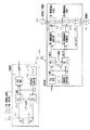
以下、本発明を教示装置であるティーチペンダント10と制御部20とが無線通信を行うロボット制御装置30に具体化した第1実施形態を図1及び図2を参照して説明する。このロボット制御装置30が制御するロボットは、例えば溶接ロボットや、搬送ロボット等である。
(First embodiment)
Hereinafter, a first embodiment in which the present invention is embodied in a
(1. ティーチペンダント10)
図1に示すように可搬式操作部としてのティーチペンダント10は2つの接点11a,11bを持つ非常停止スイッチ11と、該接点11a,11bの開閉状態をそれぞれモニタしてモニタ結果を送信する第1CPU12、第2CPU13を備えている。なお、本実施形態では、図1に示すように該接点11aはGNDに接続されるとともに接点11bは電源Vccに接続されているが、接点11a,11bの接続は限定されるものではない。例えば、両接点をともに電源に接続したり、GNDに接続したり、或いは接点11aを電源Vccに接続するとともに接点11bをGNDに接続してもよい。
(1. Teach pendant 10)
As shown in FIG. 1, a
第1CPU12及び第2CPU13はシリアル通信により、互いに必要な種々のデータの交信が可能とされている。
又、ティーチペンダント10は第1CPU12が作成した通信パケットを無線で送信する送信回路14、第1CPU12及び第2CPU13に供給される電源電圧の監視を行い、電源電圧が正常範囲から外れると異常と判断して両CPUにリセットを掛ける電源電圧監視回路15、及び前記各回路の電源となるバッテリ16を備えている。なお、CPUは中央演算処理装置(cental processing unit)であり、図示はしないが、ROM及びRAMを備えている。なお、前記正常範囲は、第1CPU12及び第2CPU13が正常に機能することができる範囲を持った電圧値のことである。
The first CPU 12 and the
The
非常停止スイッチ11は非常停止操作手段に相当し、第1CPU12及び第2CPU13はモニタ手段に相当し、送信回路14は第1通信手段に相当する。そして、非常停止スイッチ11は、押されて接点11a,11bが開となった場合が非常停止状態で、以下ではこれを非常停止スイッチ開、逆に非常停止状態を解除し接点11a,11bが閉となった場合を非常停止スイッチ閉とする。
The
(2.制御部20)
ロボット制御装置30の制御部20は、図1に示すように、無線送信された通信パケット(通信データ)を受信する無線送受信回路21、受信した通信パケット(通信データ)を解析処理する第3CPU22、及び第4CPU23を備えている。各CPUは、図示はしないが、ROM及びRAMを備えている。無線送受信回路21は受信した通信パケット(通信データ)を第3CPU22に入力し、又、第3CPU22はシリアル通信でその通信パケット(通信データ)を第4CPU23に入力するとともに該通信パケット(通信データ)を解析する。一方、第4CPU23は入力された通信パケット(通信データ)を解析する。
(2. Control unit 20)
As shown in FIG. 1, the
又、制御部20は主電源としての三相電源40からサーボアンプ28ヘの電力を遮断するために接点が直列回路に接続された第1電磁接触器24、第2電磁接触器25、及び両電磁接触器をそれぞれ開閉制御する第1電磁接触器制御回路26、第2電磁接触器制御回路27を備える。そして、第1電磁接触器24及び第2電磁接触器25の接点24a,25aが閉のときに、ロボットの関節軸(図示しない)を制御するサーボアンプ28から図示しないロボットの駆動源としてのモータM41に電流が供給されることにより、該モータM41が駆動されるようにされる。
In addition, the
又、サーボアンプ28からは第1電磁接触器制御回路26及び第2電磁接触器制御回路27に対してON/OFFの制御信号を出力可能にされている。具体的には、モータM41の制御中にサーボアンプ28が異常検出をしていない場合には、ONの制御信号が出力され、異常検出したときには、OFFの制御信号が第1電磁接触器制御回路26及び第2電磁接触器制御回路27に出力される。そして、サーボアンプ28からのONの制御信号により、第1電磁接触器制御回路26及び第2電磁接触器制御回路27は第1電磁接触器24及び第2電磁接触器25を閉作動する。又、サーボアンプ28からのOFFの制御信号により、第1電磁接触器制御回路26及び第2電磁接触器制御回路27は第1電磁接触器24及び第2電磁接触器25をそれぞれ開作動する。
The
又、第3CPU22及び第4CPU23は、受信した通信データの解析結果に応じて、ON/OFFの制御信号を第1電磁接触器制御回路26及び第2電磁接触器制御回路27に対してそれぞれ出力可能にされている。第3CPU22及び第4CPU23からONの制御信号が出力されることにより、第1電磁接触器制御回路26及び第2電磁接触器制御回路27は第1電磁接触器24、及び第2電磁接触器25をそれぞれ閉作動する。又、第3CPU22及び第4CPU23からOFFの制御信号が出力されることにより、第1電磁接触器制御回路26及び第2電磁接触器制御回路27は第1電磁接触器24、及び第2電磁接触器25をそれぞれ開作動する。第3CPU22及び第4CPU23から出力されるOFFの制御信号は非常停止信号に相当する。
The
制御部20は第3CPU22及び第4CPU23の電源電圧を監視する電源電圧監視回路29を備えている。電源電圧監視回路29は第3CPU22及び第4CPU23に供給される電源電圧の監視をそれぞれ行い、電源電圧が正常範囲から外れると異常と判断して両CPUにリセットを掛ける。なお、この正常範囲は、第3CPU22及び第4CPU23が正常に機能することができる電圧値のことである。第3CPU22及び第4CPU23は、リセットが掛けられると、第1電磁接触器制御回路26及び第2電磁接触器制御回路27に対して、OFFの制御信号を出力するようにされている。又、第3CPU22及び第4CPU23による第1電磁接触器制御回路26及び第2電磁接触器制御回路27に対する制御信号の初期値は、OFFの制御信号とされている。
The
ここで、無線送受信回路21は第2通信手段に相当し、第1電磁接触器24,第2電磁接触器25は遮断手段に相当し、第1電磁接触器制御回路26及び第2電磁接触器制御回路27は遮断制御手段に相当し、第3CPU22及び第4CPU23は通信データ解析手段に相当する。
Here, the wireless transmission /
(第1実施形態の作用)
さて、上記のように構成されたロボット制御装置30の作用を説明する。
(1. ティーチペンダント10の処理)
(1−1. 第2CPU13の処理)
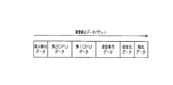
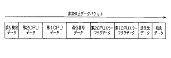
ティーチペンダント10の第2CPU13は、所定の制御周期で非常停止スイッチ11の状態を監視する。そして、下記の手順で、宛先データ(すなわち、宛先アドレス)、送信元データ(すなわち、送信元アドレス)、通信番号データとしての送信番号データ、第1CPUデータ、第2CPUデータ、誤り検出データにて構成される通信パケットとしての「非常停止データパケット」を生成する(図2参照)。
(Operation of the first embodiment)
Now, the operation of the
(1. Treatment of teach pendant 10)
(1-1. Processing of Second CPU 13)
The
なお、宛先データ、送信元データ、送信番号データ、第1CPUデータ、第2CPUデータ、誤り検出データは通信データを構成するデータである。この通信データは、予め定められた通信プロトコルに従ってパケットの形式で作成される。又、宛先データ、送信元データ、送信番号データ、誤り検出データは通信エラー検出データに相当する。 Note that destination data, transmission source data, transmission number data, first CPU data, second CPU data, and error detection data are data constituting communication data. This communication data is created in the form of a packet according to a predetermined communication protocol. The destination data, transmission source data, transmission number data, and error detection data correspond to communication error detection data.
すなわち、第2CPU13は、宛先データには図示しないROMに記憶されるとともに予めパラメータで定められた送信先の第4CPU23のデータをセットし、送信元データには予めパラメータで定められた送信元のティーチペンダント10の第2CPU13のデータをセットする。
That is, the
送信番号データは前回送信した送信番号データに1が加えられることにより更新される。
第2CPU13は、第1CPUデータには初期値として、非常停止スイッチ11の接点11aが開であるとしたデータをセットするとともに第2CPUデータには第2CPU13が「非常停止データパケット」を作成する直前に検出した非常停止スイッチ11の接点11bの開閉状態をセットする。
The transmission number data is updated by adding 1 to the previously transmitted transmission number data.
The
なお、第1CPUデータ及び第2CPUデータにセットされるものとしては、初期値以外に、接点11a、11bが開状態のときの「非常停止スイッチ開」と、接点11a,11bが閉状態のときの「非常停止スイッチ閉」がある。「非常停止スイッチ開」と「非常停止スイッチ閉」は、モニタ結果に相当する。 In addition to the initial values, the first CPU data and the second CPU data are set to “emergency stop switch open” when the contacts 11a and 11b are open, and when the contacts 11a and 11b are closed. There is “Emergency stop switch closed”. “Emergency stop switch open” and “Emergency stop switch closed” correspond to the monitoring results.
以上のように全てのデータをセットした上で、第2CPU13は合成されたデータの誤り検出データを計算して更新する。誤り検出データの計算としては、例えば、CRC(Cyclic Redundancy Check)方式や、垂直パリティチェック方式或いは水平パリティチェック方式等があるが、限定されるものではない。本実施形態では、CRC方式を採用している。第2CPU13はこうして生成された「非常停止データパケット」をシリアル通信にて、第1CPU12に送信する。
After setting all the data as described above, the
(1−2. 第1CPU12の処理)
第1CPU12は第2CPU13と同期して、所定の制御周期で非常停止スイッチ11の状態を監視する。そして、第1CPU12は第2CPU13からシリアル通信により「非常停止データパケット」(通信パケット)を受け取り、このデータに含まれる誤り検出データを使用して「非常停止データパケット」のデータが正しいことを確認する。そして、第1CPU12は、このパケットの入力直前に検出した非常停止スイッチ11の接点11aの開閉状態を第1CPUデータにセットする。以上のデータを更新した上で、合成されたデータの誤り検出データを計算して更新する。第1CPU12はこうして生成された「非常停止データパケット」(通信パケット)を送信回路14に送信する。
(1-2. Processing of the first CPU 12)
The first CPU 12 monitors the state of the
このように、宛先データは受信側の第4CPU23に対してユニークに決められたデータ(固有のデータ)である。又、送信元データは送信側の第2CPU13に対してユニークに決められたデータ(固有のデータ)である。送信番号データは送信データ毎に設定されたデータで、送信毎に更新することにより、送信された順番を特定することができるデータである。第1CPUデータは、第1CPU12が非常停止スイッチ11の接点11aの開閉状態をモニタしたデータである。第2CPUデータは、第2CPU13が非常停止スイッチ11の接点11bの開閉状態をモニタしたデータである。又、誤り検出データは、宛先データ、送信元データ、送信番号データ、第1CPUデータ、第2CPUデータを合成したデータから誤り検出演算により生成されたデータである。
Thus, the destination data is data (unique data) uniquely determined for the fourth CPU 23 on the receiving side. The transmission source data is data (unique data) uniquely determined for the
ティーチペンダント10の送信回路14は、第1CPU12からセットされた「非常停止データパケット」を無線信号として、制御部20の無線送受信回路210に送信する(図2参照)。
The
(2. 制御部20の処理)
(2−1. 第3CPU22の処理)
次に無線送受信回路210は、「非常停止データパケット」を無線信号として受信し、第3CPU22に送信する。第3CPU22は送信された「非常停止データパケット」を図示しないRAM等に書き込みした後、該「パケット」を第4CPU23にシリアル通信で送信する。
(2. Processing of control unit 20)
(2-1. Processing of the third CPU 22)
Next, the radio transmission / reception circuit 210 receives the “emergency stop data packet” as a radio signal and transmits it to the
その後、第3CPU22は誤り検出データを使用して、「非常停止データパケット」のデータに誤りがないかを確認する。第3CPU22は確認で誤りがあった場合は後述するエラー処理Aを行う。
Thereafter, the
「非常停止データパケット」のデータに誤りがない場合、第3CPU22は「非常停止データパケット」のデータから、まず、宛先データ、送信元データを予めROMに格納されて予めパラメータとして設定されている宛先データ、送信元データと比較し、いずれかが一致しない場合は後述するエラー処理Bを行う。
If there is no error in the data of the “emergency stop data packet”, the
宛先データ、送信元データが正しい場合は、第3CPU22は送信番号データが、前回の制御周期において受信した「非常停止データパケット」の送信番号データに1を加えられた物になっているかを確認する。第3CPU22は確認で送信番号データの異常があった場合、すなわち、前回の制御周期において受信した「非常停止データパケット」の送信番号データに1を加えられた物になっていない場合は、後述するエラー処理Aを行う。送信番号データに異常がない場合、第3CPU22はここで第1CPUデータ及び第2CPUデータを確認する。
When the destination data and the transmission source data are correct, the
第3CPU22は、第1CPUデータ及び第2CPUデータがともに「非常停止スイッチ閉」であれば、第1電磁接触器制御回路26へONの制御信号を出力し、いずれか一方でも「非常停止スイッチ開」であれば、第1電磁接触器制御回路26へOFFの制御信号を出力する。
If both the first CPU data and the second CPU data are “emergency stop switch closed”, the
第1電磁接触器制御回路26は、第3CPU22からOFFの制御信号が入力されると、第1電磁接触器制御回路26に対する他の制御信号の入力状態には拘わらず、第1電磁接触器24へOFFの制御信号を出力する。これによって、第1電磁接触器24の接点24aが開となり、サーボアンプ28ヘの主電源供給が停止し、図示しないロボットが停止する。
When an OFF control signal is input from the
このように、第1CPUデータ、第2CPUデータが「非常停止スイッチ開」の場合は、これらのデータは非常停止指令として機能している。
ここで、異常があった場合のエラー処理A,Bについて述べる。
Thus, when the first CPU data and the second CPU data are “emergency stop switch open”, these data function as an emergency stop command.
Here, error processing A and B when there is an abnormality will be described.
(2−1−1. エラー処理A)
誤り検出データによる確認で異常があった場合、送信番号データが正しく更新されていなかった場合(すなわち、送信番号データの異常の場合)、第3CPU22は即座に第1電磁接触器制御回路26へOFFの制御信号を出力する。
(2-1-1. Error processing A)
If there is an abnormality in the confirmation based on the error detection data, or if the transmission number data has not been updated correctly (that is, if the transmission number data is abnormal), the
なお、誤り検出データによる確認で異常があった場合、及び送信番号データが正しく更新されていなかった場合は、通信エラーとして判定されていることになる。このように誤り検出データ、及び送信番号データは、通信エラー検出のためのが通信エラー検出データとなっている。 If there is an abnormality in the confirmation using the error detection data, and if the transmission number data is not correctly updated, it is determined as a communication error. As described above, the error detection data and the transmission number data are communication error detection data for detecting a communication error.
これによって第1電磁接触器制御回路26は、第1電磁接触器制御回路26に対する他の制御信号の入力状態には拘わらず、第1電磁接触器24へOFFの制御信号を出力するため、第1電磁接触器24の接点が開となり、サーボアンプ28ヘの主電源供給が停止し、図示しないロボットが停止する。
Thus, the first electromagnetic
なお、以下、第1電磁接触器制御回路26へOFFの制御信号を出力すると記した場合は、結果として第1電磁接触器24の接点が開となり、サーボアンプ28ヘの主電源供給が停止し、ロボットが停止することになるが、説明が重複するため、記述としては省略し、「第1電磁接触器制御回路26へOFFの制御信号を出力する。」とのみ記述する。
Hereinafter, when it is described that an OFF control signal is output to the first electromagnetic
(2−1−2. エラー処理B)
宛先データの異常、及び送信元データの異常のいずれか一方を少なくとも検出した場合は、第3CPU22は受信したデータを破棄し、次回のデータ受信を待つ。このように宛先データの異常、及び送信元データが異常と判定されることは、通信エラーが検出されていることであり、これらのデータが通信エラー検出のための通信エラー検出データとなっている。
(2-1-2. Error processing B)
When at least one of the abnormality of the destination data and the abnormality of the transmission source data is detected, the
(2.2 第4CPU23の処理)
次に、第4CPU23の処理について説明する。
第4CPU23は受信した「非常停止データパケット」の誤り検出データを使用して、「非常停止データパケット」のデータに誤りがないかを確認する。確認で誤りがあった場合は、第4CPU23は後述するエラー処理Cを行う。
(2.2 Processing of the fourth CPU 23)
Next, the process of the fourth CPU 23 will be described.
The fourth CPU 23 uses the received error detection data of the “emergency stop data packet” to check whether the data of the “emergency stop data packet” has an error. If there is an error in the confirmation, the fourth CPU 23 performs error processing C described later.
「非常停止データパケット」のデータに誤りがない場合、第4CPU23は「非常停止データパケット」のデータから、まず、宛先データ、送信元データを予めROMに格納されてパラメータとして設定されている宛先データ、送信元データと比較し、いずれかが一致しない場合は後述するエラー処理Dを行う。 If there is no error in the “emergency stop data packet” data, the fourth CPU 23 first stores the destination data and the transmission source data from the “emergency stop data packet” data in the ROM and set as parameters in advance. Compared with the transmission source data, if either does not match, error processing D described later is performed.
宛先データ、送信元データが正しい場合は、第4CPU23は送信番号データが、前回の制御周期において受信した「非常停止データパケット」の送信番号データに1を加えられた物になっているかを確認する。第4CPU23は確認で送信番号データの異常があった場合、すなわち、前回の制御周期において受信した「非常停止データパケット」の送信番号データに1を加えられた物になっていない場合は、後述したエラー処理Cを行う。送信番号データに異常がない場合、第4CPU23はここで第1CPUデータ及び第2CPUデータを確認する。 When the destination data and the transmission source data are correct, the fourth CPU 23 confirms whether the transmission number data is obtained by adding 1 to the transmission number data of the “emergency stop data packet” received in the previous control cycle. . If there is an abnormality in the transmission number data in the confirmation, that is, if the transmission number data of the “emergency stop data packet” received in the previous control cycle is not one, the fourth CPU 23 will be described later. Error processing C is performed. If there is no abnormality in the transmission number data, the fourth CPU 23 confirms the first CPU data and the second CPU data here.
第4CPU23は、第1CPUデータ及び第2CPUデータがともに「非常停止スイッチ閉」であれば、第2電磁接触器制御回路27へONの制御信号を出力し、いずれか一方でも「非常停止スイッチ開」であれば、第2電磁接触器制御回路27へOFFの制御信号を出力する。
If both the first CPU data and the second CPU data are “emergency stop switch closed”, the fourth CPU 23 outputs an ON control signal to the second electromagnetic
第2電磁接触器制御回路27は、第4CPU23からOFFの制御信号を入力されると、第2電磁接触器制御回路27に対する他の制御信号の入力状態には拘わらず、第2電磁接触器25へOFFの制御信号を出力する。これによって、第2電磁接触器25の接点25aが開となり、サーボアンプ28ヘの主電源供給が停止し、図示しないロボットが停止する。
When an OFF control signal is input from the fourth CPU 23 to the second electromagnetic
ここで、異常があった場合のエラー処理C,Dについて述べる。
(2−2−1. エラー処理C)
誤り検出データによる確認で異常があった場合、送信番号データが正しく更新されていなかった場合(すなわち、送信番号データの異常の場合)、第4CPU23は即座に第2電磁接触器制御回路27へOFFの制御信号を出力する。
Here, error processing C and D when there is an abnormality will be described.
(2-2-1. Error handling C)
If there is an abnormality in the confirmation based on the error detection data, or if the transmission number data has not been updated correctly (that is, if the transmission number data is abnormal), the fourth CPU 23 immediately turns off the second electromagnetic
なお、誤り検出データによる確認で異常があった場合、及び送信番号データが正しく更新されていなかった場合は、通信エラーとして判定されていることになる。これによって、第2電磁接触器制御回路27は、第2電磁接触器制御回路27に対する他の制御信号の入力状態には拘わらず、第2電磁接触器25へOFFの制御信号を出力する。このため、第2電磁接触器25の接点25aが開となり、サーボアンプ28ヘの主電源供給が停止し、ロボットが停止する。
If there is an abnormality in the confirmation using the error detection data, and if the transmission number data is not correctly updated, it is determined as a communication error. Thus, the second electromagnetic
なお、以下、第2電磁接触器制御回路27へOFFの制御信号を出力すると記した場合は、結果として第2電磁接触器25の接点25aが開となり、サーボアンプ28ヘの主電源供給が停止し、図示しないロボットが停止することになるが、説明が重複するため、記述としては省略し、「第2電磁接触器制御回路27へOFFの制御信号を出力する。」とのみ記述する。
Hereinafter, when it is described that an OFF control signal is output to the second electromagnetic
(2−2−2. エラー処理D)
宛先データの異常、或いは送信元データの異常のいずれか一方を少なくとも検出した場合は、第4CPU23は受信したデータの同定不能による通信エラーとして受信したデータを破棄し、次回のデータ受信を待つ。
(2-2-2. Error processing D)
If at least one of the destination data abnormality and the transmission source data abnormality is detected, the fourth CPU 23 discards the received data as a communication error due to the inability to identify the received data, and waits for the next data reception.
(2−3.電源電圧監視)
次に、電源電圧監視について説明する。
ティーチペンダント10の電源電圧監視回路15は、第1CPU12及び第2CPU13に供給される電源電圧の監視を行い、電源電圧が正常範囲から外れた場合、異常と判断して両CPUに強制的にリセットを掛ける。この結果、第1CPU12及び第2CPU13側では、送信が途絶え、ティーチペンダント10に設けられた表示装置やアラーム(ともに図示しない)にてその旨を警告し、作業者に知らせる。
(2-3. Power supply voltage monitoring)
Next, power supply voltage monitoring will be described.
The power supply voltage monitoring circuit 15 of the
一方、制御部20の電源電圧監視回路29は、第3CPU22及び第4CPU23に供給される電源電圧の監視を行い、電源電圧が正常範囲から低下したり、超えたりした場合には、強制的に両CPUにリセットを掛ける。
On the other hand, the power supply
この結果、第1電磁接触器制御回路26、及び第2電磁接触器制御回路27に対してOFFの制御信号をそれぞれ出力できる。
さて、本実施形態によれば、以下のような特徴がある。
As a result, an OFF control signal can be output to the first electromagnetic
Now, according to this embodiment, there are the following features.
(1) 本実施形態のロボット制御装置30は、制御部20における第3CPU22、第4CPU23のそれぞれが、通信データに含まれるモニタ結果及び予め定められた通信プロトコルに従って作成された通信エラー検出データを解析する。そして、第3CPU22、第4CPU23がモニタ結果及び通信エラー検出データの解析結果に応じて第1電磁接触器制御回路26、第2電磁接触器制御回路27にOFFの制御信号を出力することにより、モニタ結果や通信エラーの内容に応じてロボットのモータM41への電力が遮断される。
(1) In the
この結果、本実施形態ではティーチペンダント10と制御部20間の通信を無線化する際、単一の故障で機械の非常停止動作の安全機能が損なわれることのないように2重化された2重化されたハードウエア回路と、最小限の通信回路でありながら信頼性を確保した通信プロトコルによって信頼性の高い非常停止通信を行うことができる。
As a result, in the present embodiment, when the communication between the
(2) 本実施形態では、通信データは、通信エラー検出データとして宛先データ及び送信元データを含む通信パケットにて構成される。そして、第3CPU22及び第4CPU23は、該通信データに含まれる宛先データ及び送信元データに基づいて該通信データの同定を行い、同定ができなかった場合には、通信データの同定不能による通信エラーとして次回の受信を待つようにした。
(2) In the present embodiment, the communication data is composed of communication packets including destination data and transmission source data as communication error detection data. Then, the
この結果、宛先データ、送信元データが付加された通信パケットを使用することにより、通信データを同定することができ、このことによって通信データの信頼性を確保することができる(安全通信)。 As a result, the communication data can be identified by using the communication packet to which the destination data and the transmission source data are added, and thereby the reliability of the communication data can be ensured (safety communication).
(3) 本実施形態では、通信データは、通信エラー検出データとして通信データが作成される毎に更新される通信番号データ(送信番号データ)を含む通信パケットにて構成される。そして、第3CPU22及び第4CPU23は、該通信番号データ(送信番号データ)に基づく通信エラーの場合に第1電磁接触器制御回路26及び第2電磁接触器制御回路27を制御して第1電磁接触器24及び第2電磁接触器25を遮断動作させる。
(3) In the present embodiment, the communication data is composed of communication packets including communication number data (transmission number data) that is updated each time communication data is created as communication error detection data. Then, the
この結果、本実施形態によれば、通信番号データ(送信番号データ)が付加された通信を使用すると、通信番号データが更新されていない場合、通信データの異常が検出できるため、このことによって通信データ(送信データ)の信頼性を確保することができる(安全通信)。 As a result, according to the present embodiment, when communication using communication number data (transmission number data) is used, an abnormality in communication data can be detected when the communication number data is not updated. Reliability of data (transmission data) can be secured (safety communication).
(4) 本実施形態では、通信データは、通信エラー検出データとして誤り検出データを含む通信パケットにて構成される。そして、第3CPU22及び第4CPU23は、誤り検出データに基づいて、通信データがデータ異常か否かを判定し、データ異常の場合には、第1電磁接触器制御回路26及び第2電磁接触器制御回路27を制御して第1電磁接触器24及び第2電磁接触器25を遮断動作させる。
(4) In the present embodiment, the communication data is configured by a communication packet including error detection data as communication error detection data. Then, the
この結果、本実施形態によれば、誤り検出データが付加された通信パケットを使用することにより、通信データ(送信データ)の異常を検出できるため、このことによって通信データの信頼性を確保することができる(安全通信)。 As a result, according to this embodiment, by using a communication packet to which error detection data is added, it is possible to detect an abnormality in the communication data (transmission data), thereby ensuring the reliability of the communication data. (Safety communication)
(5) 本実施形態では、第3CPU22及び第4CPU23の電源電圧の異常を検出し、異常を検出した際には第3CPU22及び第4CPU23にリセットを掛ける電源電圧監視回路29(第2電源電圧監視手段)を設けた。そして、第3CPU22及び第4CPU23は、リセットが掛けられた際には、第1電磁接触器制御回路26及び第2電磁接触器制御回路27にOFFの制御指針号(非常停止信号)を出力するようにした。この結果、制御部20内の通信の信頼性を高めることができる。
(5) In this embodiment, the power supply voltage monitoring circuit 29 (second power supply voltage monitoring means) detects an abnormality in the power supply voltages of the
(6) ここで、本実施形態において、送信番号データ、誤り検出データ、宛先データ及び送信元データを用いることにより検出できる通信異常を表1に示す。表1に示すように、本実施形態において、右の検出方法の欄の記載によって、左の欄の通信異常が検出できる。 (6) Here, in this embodiment, Table 1 shows communication abnormalities that can be detected by using transmission number data, error detection data, destination data, and transmission source data. As shown in Table 1, in the present embodiment, the communication abnormality in the left column can be detected by the description in the right detection method column.
次にティーチペンダント100と制御部200とが無線通信を行うロボット制御装置300に具体化した第2実施形態を、図3〜11を参照して説明する。このロボット制御装置300が制御するロボットは、例えば溶接ロボットや、搬送ロボット等であるが、これらのロボットに限定されるものではない。
Next, a second embodiment embodied in a
(1. ティーチペンダント100)
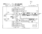
図3に示すように可搬式操作部としてのティーチペンダント100は2つの接点110a,110bを持つ非常停止スイッチ110と、該接点110a,110bの開閉状態をそれぞれモニタしてモニタ結果を送信する第1CPU120、第2CPU130を備えている。なお、本実施形態では、図3に示すように該接点110aはGNDに接続されるとともに接点110bは電源Vccに接続されているが、第1実施形態と同様に限定されるものではない。各CPUは、それぞれバス124,134で接続されるROM121,131,RAM122,132及びカレンダIC123,133を有する。
(1. Teach pendant 100)
As shown in FIG. 3, a
第1CPU120及び第2CPU130はシリアル通信により、互いに必要な種々のデータの交信が可能とされている。送受信制御回路140はバス124を介して第1CPU120に接続されるとともに、第1CPU120が作成した非常停止データパケットに基づいて無線送信データパケットを作成して無線送受信回路150に送信する。
The
又、無線送受信回路150は前記無線送信データパケットを無線でロボット制御装置300の制御部200に送信するとともに、制御部200からの無線応答データパケットを受信し、送受信制御回路140に送信する。電源電圧監視・ウオッチドッグ回路160は、電源電圧監視回路とウオッチドッグ回路とを備えているとともに電源電圧監視回路は第1CPU120及び第2CPU130に供給される電源電圧の監視を行い、電源電圧が正常範囲から外れると異常と判断して両CPUにリセットを掛けるようにされている。なお、前記正常範囲は、第1CPU120及び第2CPU130が正常に機能することができる範囲を持った電圧値のことである。
Further, the wireless transmission /
さらに、電源電圧監視・ウオッチドッグ回路160のウオッチドッグ回路は、第1CPU120及び第2CPU130が正常に動作している場合には、第1CPU120及び第2CPU130から定期的なアクセス(すなわち、ウオッチドッグクリア信号の出力)を受けるようにされている。そして、電源電圧監視・ウオッチドッグ回路160は、第1CPU120、第2CPU130に何らかの異常が発生して、定期的なアクセスが無くなった場合には、それを検出して両CPUに対して強制的にリセットを掛けることができるようにされている。電源電圧監視・ウオッチドッグ回路160は、第1電源電圧監視手段、及び第1ウオッチドッグ手段に相当する。又、ティーチペンダント100には、前記各回路の電源となるバッテリ170を備えている。
Further, the watchdog circuit of the power supply voltage monitoring / watchdog circuit 160 is configured to perform periodic access (that is, a watchdog clear signal of the watchdog clear signal) from the
非常停止スイッチ110は非常停止操作手段に相当し、第1CPU120及び第2CPU130はモニタ手段に相当し、無線送受信回路150は第1通信手段に相当する。そして、非常停止スイッチ110は、非常停止スイッチを押して回路が開となった場合が非常停止状態で、以下ではこれを非常停止スイッチ開、逆に非常停止状態を解除し回路が閉となった場合を非常停止スイッチ閉とする。
The
(2. 制御部200)
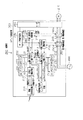
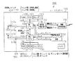
ロボット制御装置300の制御部200は、図4に示すように無線送信された無線送信データパケットを受信するとともに無線応答データパケットを送信する無線送受信回路210、及び該無線送受信回路210に接続されるとともにデータの書き込み読み出しが可能な送受信制御回路215を備えている。
(2. Control unit 200)
As shown in FIG. 4, the control unit 200 of the
又、制御部200は、受信した無線送信データパケットを解析処理するとともに、応答データパケットを作成する第1非常停止制御CPU220及び第2非常停止制御CPU230を備えている。各CPUは、バス221,231を介して接続されたROM222,232,RAM223,233、及びカレンダIC224,234を有する。
The control unit 200 also includes a first emergency
又、制御部200は主電源としての三相電源400からサーボアンプ280ヘの電力を遮断するために接点240a,250aが直列回路に接続された第1電磁接触器240、第2電磁接触器250、及び両電磁接触器をそれぞれ開閉制御する第1非常停止制御回路260、第2非常停止制御回路270を備える。そして、第1電磁接触器240及び第2電磁接触器250の接点240a,250aが閉のときに、ロボットの関節軸(図示しない)を制御するサーボアンプ280から図示しないロボットの駆動源としてのモータM410に電流が供給されることにより、該モータM410が駆動される。
The control unit 200 also includes a first
サーボ制御用回路285は、サーボアンプ280を制御するとともに、第1非常停止制御回路260及び第2非常停止制御回路270に対して、ON/OFFの制御信号を出力する。
The
又、第1非常停止制御回路260は、第1非常停止制御CPU220とサーボ制御用回路285からともにONの制御の信号を受けたときに第1電磁接触器240にONの制御信号を出力し、第1電磁接触器240の接点240aを閉作動する。又、第1非常停止制御回路260は、第1非常停止制御CPU220からOFFの制御信号を入力した際には、サーボ制御用回路285からの制御信号の入力状態に拘わらず第1電磁接触器240への制御信号をOFFとし、第1電磁接触器240の接点240aを開作動する。一方、第2非常停止制御回路270は、第2非常停止制御CPU230とサーボ制御用回路285からともにONの制御の信号を受けたときに第2電磁接触器250にONの制御信号を出力し、第2電磁接触器250の接点250aを閉作動する。又、第2非常停止制御回路270は、第2非常停止制御CPU230からOFFの制御信号を入力した際には、サーボ制御用回路285からの制御信号の入力状態に拘わらず第2電磁接触器250への制御信号をOFFとし、第2電磁接触器250の接点250aを開作動する。
Further, the first emergency
ここで、第1非常停止制御CPU220及び第2非常停止制御CPU230から出力されるOFFの制御信号は非常停止信号に相当する。
制御部200は、制御部200が備える回路(第1非常停止制御CPU220及び第2非常停止制御CPU230を含む)の電源電圧を監視するとともに第1非常停止制御CPU220及び第2非常停止制御CPU230が正常に動作していることを監視する電源電圧監視・ウオッチドッグ回路290を備えている。電源電圧監視・ウオッチドッグ回路290の電源電圧回路は、回路が電源電圧が正常範囲から外れた場合、異常と判断して両CPUにリセットを掛ける。なお、この正常範囲は、各回路が正常に機能することができる電圧値のことである。
Here, the OFF control signal output from the first emergency
The control unit 200 monitors the power supply voltage of a circuit (including the first emergency
第1非常停止制御CPU220及び第2非常停止制御CPU230は、リセットが掛けられると、第1非常停止制御回路260及び第2非常停止制御回路270に対して、OFFの制御信号を出力するようにされている。又、第1非常停止制御CPU220及び第2非常停止制御CPU230による第1非常停止制御回路260及び第2非常停止制御回路270に対する制御信号の初期値は、OFFの制御信号とされている。
The first emergency
又、電源電圧監視・ウオッチドッグ回路290のウオッチドッグ回路は、第1非常停止制御CPU220及び第2非常停止制御CPU230が正常に動作している場合には、第1非常停止制御CPU220及び第2非常停止制御CPU230から定期的なアクセス(すなわち、ウオッチドッグクリア信号の出力)を受けるようにされている。そして、電源電圧監視・ウオッチドッグ回路290は、第1非常停止制御CPU220、第2非常停止制御CPU230に何らかの異常が発生して、定期的なアクセスが無くなった場合には、それを検出して両CPUに対して強制的にリセットを掛けることができるようにされている。
In addition, the watchdog circuit of the power supply voltage monitoring /
このリセットが掛けられると、第1非常停止制御CPU220及び第2非常停止制御CPU230は、第1非常停止制御回路260及び第2非常停止制御回路270に対して、OFFの制御信号を出力するようにされている。
When this reset is applied, the first emergency
ここで、無線送受信回路210は第2通信手段に相当し、第1電磁接触器240,第2電磁接触器250は遮断手段に相当し、第1非常停止制御回路260及び第2非常停止制御回路270は遮断制御手段に相当し、第1非常停止制御CPU220及び第2非常停止制御CPU230は通信データ解析手段に相当する。電源電圧監視・ウオッチドッグ回路290は、第2電源電圧監視手段及び第2ウオッチドッグ手段に相当する。
Here, the wireless transmission / reception circuit 210 corresponds to the second communication means, the first
(第2実施形態の作用)
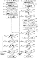
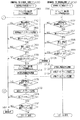
さて、上記のように構成されたロボット制御装置300の作用を図10、図11のフローチャートを参照しながら説明する。なお、このフローチャートに示される処理は、各CPUにおいて、所定の制御周期毎(例えば、0.05秒毎)に、すなわち、定期的に実行される。
(Operation of Second Embodiment)
Now, the operation of the
(1.非常停止データパケットの生成及び送信)
ティーチペンダント100の第2CPU130は、非常停止信号処理のプログラムを実行して非常停止スイッチ110の状態を監視する。そして、第2CPU130は、図10のS10〜S14の処理を行い、「非常停止データパケット」を生成する(図5参照)。
(1. Generation and transmission of emergency stop data packet)
The
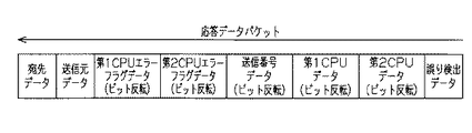
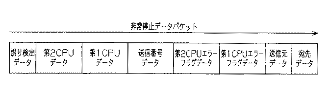
図5に示すように「非常停止データパケット」は、宛先データ、送信元データ、第1CPUエラーフラグ、第2CPUエラーフラグ、通信番号データとしての送信番号データ、第1CPUデータ、第2CPUデータ、誤り検出データにて構成される。 As shown in FIG. 5, the “emergency stop data packet” includes destination data, transmission source data, first CPU error flag, second CPU error flag, transmission number data as communication number data, first CPU data, second CPU data, and error detection. Consists of data.
なお、第1CPUデータ及び第2CPUデータは、第1実施形態と同様にセットされるものとしては、初期値以外に、接点が開状態のときの「非常停止スイッチ開」と、接点が閉状態のときの「非常停止スイッチ閉」がある。「非常停止スイッチ開」と「非常停止スイッチ閉」は、モニタ結果に相当する。 The first CPU data and the second CPU data are set in the same manner as in the first embodiment. In addition to the initial value, “emergency stop switch open” when the contact is open, and the contact is closed. Sometimes there is an “emergency stop switch closed”. “Emergency stop switch open” and “Emergency stop switch closed” correspond to the monitoring results.
ここで、送信番号データは通信データ(すなわち、送信データ)毎に設定されたデータであって、送信毎に1を加えて更新することにより、送信された順番を特定することができるデータである(図10のS10参照)。 Here, the transmission number data is data set for each communication data (that is, transmission data), and is data that can specify the order of transmission by updating by adding 1 for each transmission. (See S10 in FIG. 10).
第2CPU130は、第1CPUデータには初期値として、非常停止スイッチ110が開であるとしたデータをセットするとともに、第2CPUデータには、第2CPU130で直前に検出した非常停止スイッチ110の状態をセットする(図10のS12参照)。又、第2CPU130は残りのデータを作成して、「非常停止データパケット」を生成する(図10のS14参照)。
The
ここで、誤り検出データは、宛先データ、送信元データ、第1CPUエラーフラグデータ、第2CPUエラーフラグデータ、送信番号データ、第1CPUデータ、第2CPUデータを合成したデータから誤り検出演算により生成されたデータである。なお、宛先データ、送信元データ、送信番号データ、第1CPUデータ、第2CPUデータ、誤り検出データは通信データを構成するデータである。この通信データは、予め定められた通信プロトコルに従ってパケットの形式で作成される。又、宛先データ、送信元データ、送信番号データ、誤り検出データは通信エラー検出データに相当する。 Here, the error detection data is generated by error detection calculation from data obtained by combining destination data, transmission source data, first CPU error flag data, second CPU error flag data, transmission number data, first CPU data, and second CPU data. It is data. Note that destination data, transmission source data, transmission number data, first CPU data, second CPU data, and error detection data are data constituting communication data. This communication data is created in the form of a packet according to a predetermined communication protocol. The destination data, transmission source data, transmission number data, and error detection data correspond to communication error detection data.
すなわち、第2CPU130は、宛先データにはROM131に記憶されるとともに予めパラメータで定められた送信先の第2非常停止制御CPU230のデータをセットし、送信元データには予めパラメータで定められた送信元のティーチペンダント100の第2CPU130のデータをセットする。
That is, the
なお、前記宛先データ(すなわち、宛先アドレス)は送信先の制御部200の第2非常停止制御CPU230に対してユニーク(固有のデータ)に決められたデータである。又、前記送信元データ(すなわち、送信元アドレス)は送信元のティーチペンダント100の第2CPU130に対してユニーク(固有のデータ)に決められたデータである。
The destination data (that is, the destination address) is data determined uniquely (unique data) for the second emergency stop control CPU 230 of the transmission destination control unit 200. The transmission source data (that is, the transmission source address) is data determined uniquely (unique data) with respect to the
(第1CPUエラーフラグデータ及び第2CPUエラーフラグデータ)
ここで、第1CPUエラーフラグデータ及び第2CPUエラーフラグデータについて説明する。
(First CPU error flag data and second CPU error flag data)
Here, the first CPU error flag data and the second CPU error flag data will be described.
第1CPUエラーフラグデータは、第1CPU120が何らかの異常をそれぞれ検出したときに、それぞれそのエラー状態を書き示すデータである。
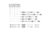
図9には、第1CPUエラーフラグデータ及び第2CPUエラーフラグデータの例が示されている。同図に示すように、第1CPUエラーフラグデータには、右から左に向かって順に、非常停止データCRC異常、非常停止データタイムアウト異常、応答データCRC異常、応答データ不一致異常、及び応答データタイムアウト異常の各種フラグをセット可能である。第1CPUエラーフラグには、初期値例として、全てのビット(すなわち、フラグ)に「異常」を表す「1」がセットされている(”11111”)。
The first CPU error flag data is data indicating the error state when the
FIG. 9 shows an example of the first CPU error flag data and the second CPU error flag data. As shown in the figure, the first CPU error flag data includes, in order from right to left, an emergency stop data CRC error, an emergency stop data timeout error, a response data CRC error, a response data mismatch error, and a response data timeout error. The various flags can be set. In the first CPU error flag, as an example of an initial value, “1” representing “abnormal” is set in all bits (that is, flags) (“11111”).
又、第2CPUエラーフラグデータは、第2CPUが何らかの異常を検出したときにそのエラー状態を書き示すデータである。第2CPUエラーフラグは、第1CPUエラーフラグデータと同様に構成されている。該第2CPUエラーフラグには、直前に検出して更新した第2CPU130で検出する異常パラメータの状態をセットする。
The second CPU error flag data is data indicating the error state when the second CPU detects any abnormality. The second CPU error flag is configured in the same manner as the first CPU error flag data. In the second CPU error flag, the state of the abnormal parameter detected by the
なお、第2CPUエラーフラグデータの初期値例としては、非常停止データCRC異常及び非常停止データタイムアウト異常には「0」がそれぞれセットされ、他のビットには、「異常」を表す「1」がセットされている(”11100”)。これらのビット(すなわち、フラグ)は、それぞれのビット(フラグ)に関する判定において、第1CPU120に,第2CPU130に異常と判定されない場合は、正常として「0」にリセットされる。
As an example of the initial value of the second CPU error flag data, “0” is set for the emergency stop data CRC abnormality and the emergency stop data timeout abnormality, respectively, and “1” representing “abnormal” is set in the other bits. It is set (“11100”). These bits (that is, flags) are reset to “0” as normal when the
ここで、フローチャートの話に戻して、以上の全てのデータをセットした上で、合成されたデータの誤り検出データを計算して更新する。第2CPU130はこうして生成された「非常停止データパケット」をシリアル通信にて、第1CPU120に送信する(図10のS16参照)。この後、第2CPU130は、S18において、カレンダIC133のタイムアウト検出用カレンダを読み込みする。
Returning to the flowchart, after setting all the above data, the error detection data of the synthesized data is calculated and updated. The
第1CPU120は、図10に示すように非常停止信号処理のプログラムを第2CPU130が行う非常停止信号処理と同期して所定の制御周期で実行しているとともに、この非常停止信号処理がスタートした直後のS30においてカレンダIC123のタイムアウト検出用カレンダを読み込みしている。
As shown in FIG. 10, the
S32では、第1CPU120は、第2CPU130から受け取りした「非常停止データパケット」が読み込みしたタイムアウト検出用カレンダの値に基づいて規定時間内に受信したか否かを判断し、該規定時間内に受信していない場合には、「NG」と判定して、後述するS54の異常処理を行う。なお、本明細書において、規定時間は、予め定められた時間であって、例えば数msec〜数百msecの大きさをいう。そして、S34において、第1CPU120は、受け取りした「非常停止データパケット」に含まれる誤り検出データを使用してデータが正しいことを確認後、第1CPUエラーフラグを直前に検出して更新した異常パラメータの状態に更新する。
In S32, the
又、S36において、第1CPUデータに第1CPU120で、このパケットの入力直前に検出した非常停止スイッチ110の状態をセットする。以上のデータを更新した上で、S38において、合成されたデータの誤り検出データを計算して更新する。続くS40では、第1CPU120はこうして生成された「非常停止データパケット」を送受信制御回路140にバス124を経由して書き込む。
In S36, the
次に、S42において、第1CPU120はS42において、カレンダIC123のタイムアウト検出用カレンダを読み込みする。
なお、S34において、受け取りした「非常停止データパケット」に含まれる誤り検出データを使用してデータが正しくない場合には、第1CPU120は「NG」と判定して、後述するS54の異常処理を行う。
Next, in S42, the
In S34, when the error detection data included in the received “emergency stop data packet” is used and the data is not correct, the
次に、送受信制御回路140は、第1CPU120からセットされた「非常停止データパケット」に無線送信を実行するためのヘッダデータを、図6に示すように付加し「無線送信データパケット」として無線送受信回路150に送信する。ここで、前記ヘッダデータには、使用する前記通信プロトコルによって定められた、送信元ポート番号、宛先ポート番号、データサイズ、誤り検出データ等が含まれる。
Next, the transmission /
次に、ティーチペンダント100の無線送受信回路150は、送受信制御回路140から受信した「無線送信データパケット」を無線信号として送信する。
制御部200の無線送受信回路210は、「無線送信データパケット」を無線信号として受信し、送受信制御回路215に送信する。制御部200の送受信制御回路215は、無線送受信回路210から受信した「無線送信データパケット」のヘッダデータ内の誤り検出データを利用して受け取った無線送信データパケットの内容が正しいことを確認後、ヘッダデータ内の宛先ポート番号で自分宛のデータかどうかを判断する。
Next, the wireless transmission /
The wireless transmission / reception circuit 210 of the control unit 200 receives the “wireless transmission data packet” as a wireless signal and transmits it to the transmission /
そして、送受信制御回路215は自分宛であった場合は「無線送信データパケット」から「非常停止データパケット」を取り出し、第1非常停止制御CPU220から読み出し可能な状態として、第1非常停止制御CPU220に対して割り込みをかける。送受信制御回路215は自分宛でなかった場合はデータを破棄する。
Then, if the transmission /
次に、第1非常停止制御CPU220における非常停止信号処理のプログラムについて説明するが、第1非常停止制御CPU220は、図11に示すように非常停止信号処理のプログラムを第2非常停止制御CPU230が行う非常停止信号処理と同期して所定の制御周期で実行している。又、第1非常停止制御CPU220は、この非常停止信号処理がスタートした直後のS60においてカレンダIC224のタイムアウト検出用カレンダを読み込みしている。
Next, an emergency stop signal processing program in the first emergency
そして、第1非常停止制御CPU220は送受信制御回路215からの割り込みを受けて、送受信制御回路215からバス221経由で、「非常停止データパケット」をRAM223から読み出す。
The first emergency
S62では、第1非常停止制御CPU220は、読み出した「非常停止データパケット」が読み込みしたタイムアウト検出用カレンダの値に基づいて規定時間内に受信したか否かを判断し、該規定時間内に受信していない場合には、S84の異常処理を行う。
In S62, the first emergency
規定時間内に受信している場合には、S64において、第1非常停止制御CPU220は、読み出した「非常停止データパケット」をそのまま第2非常停止制御CPU230にシリアル通信で送信する。なお、第2非常停止制御CPU230における処理は後述する。
If it is received within the specified time, in S64, the first emergency
次に、S66において、第1非常停止制御CPU220は、誤り検出データを使用して、「非常停止データパケット」のデータに誤りがないかを確認する。確認で誤りがあった場合は、S84の異常処理のフェーズに移る。
Next, in S66, the first emergency
S66において、「非常停止データパケット」のデータに誤りがない場合、第1非常停止制御CPU220はS68において、「非常停止データパケット」のデータから、まず、宛先データ、送信元データをパラメータとして予め設定されている宛先データ、送信元データと比較し、いずれかが一致しない場合はS84の異常処理のフェーズに移る。
If there is no error in the data of “emergency stop data packet” in S66, the first emergency
S68において、宛先データ、送信元データが正しい場合は、S70において、第1非常停止制御CPU220は第1CPUエラーフラグデータ、第2CPUエラーフラグデータを確認し、異常がないことを確認する。又、第1非常停止制御CPU220は、送信番号データが、前回のデータに1を加えられた物になっているかを確認する。S70において、異常があった場合は第1非常停止制御CPU220は、S84の異常処理のフェーズに移る。
In S68, when the destination data and the transmission source data are correct, in S70, the first emergency
次に、S70において、第1非常停止制御CPU220は確認で問題がなかったら、S72において、カレンダIC224のタイムアウト検出用カレンダを読み込みする。
次に、S74において、第1非常停止制御CPU220は、第1CPUデータ及び第2CPUデータを確認する。ここで、両方のデータがともに非常停止スイッチ閉であれば、第1非常停止制御CPU220は、第1非常停止制御回路260へONの制御信号を出力し、いずれか一方でも非常停止スイッチ開であれば、第1非常停止制御回路260へOFFの制御信号を出力する。第1非常停止制御回路260は、非常停止制御CPUからの制御信号がOFFになると、他の入力状態には拘わらず、第1電磁接触器240へOFFの制御信号を出力する。これによって、第1電磁接触器240の接点240aが開となり、サーボアンプ280ヘの主電源供給が停止し、ロボットが停止する。
Next, in S70, if there is no problem in the confirmation, the first emergency
Next, in S74, the first emergency
このように、第1CPUデータ、第2CPUデータが非常停止スイッチ開の場合は、これらのデータは非常停止指令として機能している。
なお、第1非常停止制御CPU220は、第1非常停止制御回路260へのOFFの制御信号を出力した後、予め定められた第1電磁接触器240の動作待ち時間後に、第1電磁接触器240の接点状態をモニタ入力によりモニタする。そして、OFFの制御信号を出力したにも拘わらず、接点状態がONのままであった場合には、第1非常停止制御CPU220は、これを第1電磁接触器240の接点異常と判断する。そして、第1非常停止制御CPU220は、その旨を異常出力してエラーが解除されるまで、異常状態を保持し、入力された「非常停止データパケット」の状態に拘わらず、非常停止制御回路へOFFの制御信号を出力保持する。第1非常停止制御CPU220は監視手段に相当する。
As described above, when the first CPU data and the second CPU data are the emergency stop switch opened, these data function as an emergency stop command.
The first emergency
同様の動作を第2非常停止制御CPU230でも実施がされることにより、電磁接触器の故障による遮断不良をほぼ確実に防ぐことができる。
(異常処理(S84))
ここで、S84の異常処理について説明する。
By performing the same operation also in the second emergency stop control CPU 230, it is possible to almost certainly prevent a disconnection failure due to a failure of the magnetic contactor.
(Abnormal processing (S84))
Here, the abnormality process of S84 will be described.
規定時間内に「非常停止データパケット」が受信できなかった場合(S62で「NG」、後述するS76で「NG」)、第1非常停止制御CPU220は即座に第1非常停止制御回路260へOFFの制御信号を出力する。第1非常停止制御CPU220は、宛先データの異常、或いは送信元データの異常を検出した場合(S68で「NG」)は、受信したデータを破棄し、次回のデータ受信を待つ。
If the “emergency stop data packet” cannot be received within the specified time (“NG” in S 62, “NG” in
誤り検出データによる確認で異常があった場合(S66で「NG」)、第1CPUエラーフラグデータ、第2CPUエラーフラグデータに異常が検出された場合、送信番号データが正しく更新されていなかった場合(S70で「NG」)は、第1非常停止制御CPU220は即座に第1非常停止制御回路260へOFFの制御信号を出力する。
If there is an abnormality in the confirmation using the error detection data (“NG” in S66), an abnormality is detected in the first CPU error flag data and the second CPU error flag data, or the transmission number data is not correctly updated ( In S70, “NG”), the first emergency
このように、S66、S70において、それぞれ「NG」とされて、異常が検出された場合には、第1非常停止制御CPU220が第1非常停止制御回路260へOFFの制御信号をそれぞれ出力することを、上記の一連の処理の流れが停止した場合の歯止めとしている。
As described above, in S66 and S70, each is “NG”, and when an abnormality is detected, the first emergency
又、後述するS82で「NG」の場合は、即座に第1非常停止制御回路260へOFFの制御信号を出力する。
なお、誤り検出データによる確認で異常があった場合、及び送信番号データが正しく更新されていなかった場合は、通信エラーとして判定されていることになる。
If “NG” is determined in S82 described later, an OFF control signal is immediately output to the first emergency
If there is an abnormality in the confirmation using the error detection data, and if the transmission number data is not correctly updated, it is determined as a communication error.
これによって第1非常停止制御回路260は、他の入力状態には拘わらず、第1電磁接触器240へOFFの制御信号を出力するため、第1電磁接触器240の接点が開となり、サーボアンプ280ヘの主電源供給が停止し、ロボットが停止する。以下、第1非常停止制御回路260へOFFの制御信号を出力と記した場合は、結果として第1電磁接触器240の接点が開となり、サーボアンプ280ヘの主電源供給が停止し、ロボットが停止することになるが、説明が重複するため、記述としては省略し、「第1非常停止制御回路260へOFFの制御信号を出力する。」とのみ記述する。
As a result, the first emergency
次に、第2非常停止制御CPU230での非常停止信号処理のプログラムについて説明するが、第2非常停止制御CPU230は、図11に示すように非常停止信号処理のプログラムを第1非常停止制御CPU220が行う非常停止信号処理と同期して所定の制御周期で実行している。又、第1非常停止制御CPU220は、この非常停止信号処理がスタートした直後のS90においてカレンダIC234のタイムアウト検出用カレンダを読み込みしている。
Next, the emergency stop signal processing program in the second emergency stop control CPU 230 will be described. As shown in FIG. 11, the second emergency stop control CPU 230 executes the emergency stop signal processing program by the first emergency
そして、S92において、第2非常停止制御CPU230は、受信した「非常停止データパケット」が読み込みしたタイムアウト検出用カレンダの値に基づいて規定時間内に受信したか否かを判断し、該規定時間内に受信していない場合には、S106の異常処理を行う。 Then, in S92, the second emergency stop control CPU 230 determines whether or not the received “emergency stop data packet” is received within the specified time based on the value of the time-out detection calendar read, and within the specified time. If not received, the abnormal process of S106 is performed.
次に、S94において、第2非常停止制御CPU230は受信した「非常停止データパケット」の誤り検出データを使用して、データに誤りがないかを確認する。確認で誤りがあった場合は、第2非常停止制御CPU230はS106の異常処理のフェーズに移る。 Next, in S94, the second emergency stop control CPU 230 uses the received error detection data of the “emergency stop data packet” to check whether there is any error in the data. If there is an error in the confirmation, the second emergency stop control CPU 230 proceeds to the abnormality processing phase of S106.
S94において、確認で問題がなかったら、S96において、第2非常停止制御CPU230は、「非常停止データパケット」のデータから、まず、宛先データ、送信元データをパラメータとして予め設定されている宛先データ、送信元データと比較し、いずれかが一致しない場合はS106の異常処理のフェーズに移る。 If there is no problem in the confirmation in S94, in S96, the second emergency stop control CPU 230 starts from the data of the “emergency stop data packet” with destination data and destination data set in advance using the transmission source data as parameters. If any of them does not match with the transmission source data, the process proceeds to the abnormality processing phase of S106.
S96において、宛先データ、送信元データが正しい場合は、S98において、第2非常停止制御CPU230は第1CPUエラーフラグデータ、第2CPUエラーフラグデータを確認し、異常がないことを確認する。又、第2非常停止制御CPU230は、送信番号データが、前回のデータに1を加えられた物になっているかを確認する。S98において、第2非常停止制御CPU230は確認で異常があった場合はS106の異常処理のフェーズに移る。 If the destination data and the transmission source data are correct in S96, the second emergency stop control CPU 230 checks the first CPU error flag data and the second CPU error flag data in S98 to confirm that there is no abnormality. Further, the second emergency stop control CPU 230 confirms whether the transmission number data is obtained by adding 1 to the previous data. In S98, if there is an abnormality in the confirmation, the second emergency stop control CPU 230 proceeds to the abnormality processing phase in S106.
S98において、確認で問題がなかったら、S100において、第2非常停止制御CPU230は、次に、第1CPUデータ及び第2CPUデータを確認する。両方のデータがともに非常停止スイッチ閉であれば、第2非常停止制御回路270へONの制御信号を出力し、いずれか一方でも非常停止スイッチ開であれば、第2非常停止制御回路270へのOFFの制御信号を出力する。第2非常停止制御回路270は、第2非常停止制御CPU230からOFFの制御信号が出力されると、他の入力状態には拘わらず、第2電磁接触器250へOFFの制御信号を出力する。これによって、第2電磁接触器250の接点250aが開となり、サーボアンプ280ヘの主電源供給が停止し、ロボットが停止する。
If there is no problem in the confirmation in S98, the second emergency stop control CPU 230 next confirms the first CPU data and the second CPU data in S100. If both of the data are the emergency stop switch closed, an ON control signal is output to the second emergency
又、第2非常停止制御CPU230は第2非常停止制御回路270へOFFの制御信号を出力した後、予め定められた第2電磁接触器250の動作待ち時間後に、第2電磁接触器250の接点状態をモニタ入力によりモニタする。そして、OFFの制御信号を出力したにも拘わらず、接点状態がONのままであった場合には、第2非常停止制御CPU230はこれを第2電磁接触器250の接点異常と判断し、その旨を異常出力してエラーが解除されるまで、異常状態を保持する。そして、第2非常停止制御CPU230は、入力された「非常停止データパケット」の状態に拘わらず、第2非常停止制御回路270へOFFの制御信号の出力のままとする。第2非常停止制御CPU230は監視手段に相当する。
Further, the second emergency stop control CPU 230 outputs the OFF control signal to the second emergency
同様の動作を第1非常停止制御CPU220でも実施することにより、電磁接触器の故障による遮断不良をほぼ確実に防ぐことができる。
(異常処理(S106))
ここで、S106の異常処理について説明する。
By performing the same operation also in the first emergency
(Abnormal processing (S106))
Here, the abnormality process of S106 will be described.
規定時間内に「非常停止データパケット」が受信できなかった場合(S92で「NG」)、第2非常停止制御CPU230は即座に第2非常停止制御回路270へOFFの制御信号を出力する。
When the “emergency stop data packet” cannot be received within the specified time (“NG” in S92), the second emergency stop control CPU 230 immediately outputs an OFF control signal to the second emergency
第2非常停止制御CPU230は、宛先データの異常、或いは送信元データの異常のいずれか一方を少なくとも検出した場合(S96で「NG」)は、送信データの同定不能による通信エラーとして受信したデータを破棄し、次回のデータ受信を待つ。 When the second emergency stop control CPU 230 detects at least one of the destination data abnormality or the transmission source data abnormality (“NG” in S96), the data received as the communication error due to the inability to identify the transmission data is detected. Discard and wait for next data reception.
誤り検出データによる確認で異常があった場合(S94で「NG」)、第1CPUエラーフラグデータ、第2CPUエラーフラグデータに異常が検出された場合、送信番号データが正しく更新されていなかった場合(S98で「NG」)は、第2非常停止制御CPU230は、即座に第2非常停止制御回路270へOFFの制御信号を出力する。
If there is an abnormality in the confirmation by the error detection data (“NG” in S94), an abnormality is detected in the first CPU error flag data and the second CPU error flag data, or the transmission number data is not correctly updated ( In S98, “NG”), the second emergency stop control CPU 230 immediately outputs an OFF control signal to the second emergency
又、S94、S98において、それぞれ「NG」とされて、異常が検出された場合には、第2非常停止制御回路270へOFFの制御信号をそれぞれ出力することを、上記の一連の処理の流れが停止した場合の歯止めとしている。
Also, in S94 and S98, when “NG” is detected and an abnormality is detected, an OFF control signal is output to the second emergency
これにより、第2非常停止制御CPU230は、他の入力状態には拘わらず、第2電磁接触器250へOFFの制側言号を出力するため、第2電磁接触器250の接点250aが開となり、サーボアンプ280ヘの主電源供給が停止し、ロボットが停止する。以下、第2非常停止制御回路270へOFFの制御信号を出力と記した場合は、結果として第2電磁接触器250の接点250aが開となり、サーボアンプ280ヘの主電源供給が停止し、ロボットが停止することになるが、説明が重複するため、記述としては省略し、「第2非常停止制御回路270へOFFの制御信号を出力する。」とのみ記述する。
As a result, the second emergency stop control CPU 230 outputs an ON / OFF control signal to the second
(2. 制御部200側の応答データパケットの生成及び送信)
応答データパケットについて説明する。
S102において、第2非常停止制御CPU230は受信した「非常停止データパケット」の中のデータについて、第1CPUエラーフラグデータ、第2CPUエラーフラグデータ、送信番号データ、第1CPUデータ、第2CPUデータ、をビット反転してセットし、宛先データと送信元データを相互に入れ替えてセットする。続いて、第2非常停止制御CPU230は、上記のように合成されたデータに対して誤り検出データを計算して付加することにより、「応答データパケット」を生成する(図7参照)。
(2. Generation and transmission of response data packet on control unit 200 side)
The response data packet will be described.
In S102, the second emergency stop control CPU 230 sets the first CPU error flag data, the second CPU error flag data, the transmission number data, the first CPU data, and the second CPU data for the data in the received “emergency stop data packet”. Inverted and set, destination data and source data are set interchangeably. Subsequently, the second emergency stop control CPU 230 generates a “response data packet” by calculating and adding error detection data to the data synthesized as described above (see FIG. 7).
図7に示すように「応答データパケット」には、宛先データ、送信元データ、第1CPUエラーフラグデータ、第2CPUエラーフラグデータ、送信番号データ、第1CPUデータ、第2CPUデータ、誤り検出データが含まれる。宛先データは制御部200側から見て送信先となる、ティーチペンダント100の第2CPU130に対してユニークに決められたデータ(固有のデータ)である。又、送信元データは制御部200の第2非常停止制御CPU230に対してユニークに決められたデータ(固有のデータ)である。第1CPUエラーフラグデータ、第2CPUエラーフラグデータ、送信番号データ、第1CPUデータ及び第2CPUデータは、「非常停止データパケット」として受信されたデータがビット反転されたデータである。又、誤り検出データは、宛先データ、送信元データ、第1CPUエラーフラグデータ、第2CPUエラーフラグデータ、送信番号データ、第1CPUデータ、第2CPUデータを合成したデータから誤り検出演算により生成されたデータである。そして、この「応答データパケット」は、制御部200の第2非常停止制御CPU230により生成され、制御部200側の第1非常停止制御CPU220を経由して送信されて、ティーチペンダント100の第1CPU120及び、第1CPU120を経由して第2CPU130が受信するデータパケットとなる。
As shown in FIG. 7, the “response data packet” includes destination data, transmission source data, first CPU error flag data, second CPU error flag data, transmission number data, first CPU data, second CPU data, and error detection data. It is. The destination data is data (unique data) uniquely determined for the
S104において、第2非常停止制御CPU230は、生成された「応答データパケット」をシリアル通信により、第1非常停止制御CPU220に送信し、非常停止信号処理のプログラムの処理を一旦終了する。
In S104, the second emergency stop control CPU 230 transmits the generated “response data packet” to the first emergency
図11に示すように、S76において、第1非常停止制御CPU220は、受信した「応答データパケット」がS72で読み込みしたタイムアウト検出用カレンダの値に基づいて規定時間内に受信したか否かを判断し、該規定時間内に受信していない場合には、S84の異常処理を行う。規定時間内に受信している場合には、S78において、第1非常停止制御CPU220は、受信した「応答データパケット」をそのままバス経由で送受信制御回路215に書き込む。
As shown in FIG. 11, in S76, the first emergency
又、S80において、第1非常停止制御CPU220は、前記受信した「応答データパケット」の誤り検出データによる確認で異常があった場合(S80で「NG」の場合)は、S84の異常処理を行なう。
In S80, the first emergency
S80において異常がなければ、S82において、第1非常停止制御CPU220は、自分が受信した「非常停止データパケット」を第2非常停止制御CPU230と同様にビット反転処理等をして、応答データパケットに相当するデータに変換後、このデータと前記受信した応答データパケットとを照合する。
If there is no abnormality in S80, in S82, the first emergency
ここで、S82において、異常があった場合は、第1非常停止制御CPU220は、S84で異常処理を行う。又、S82において、異常がないと第1非常停止制御CPU220が判定した場合には、この非常停止信号処理を一旦終了する。
If there is an abnormality in S82, the first emergency
次に、送受信制御回路215は、第1非常停止制御CPU220から書き込まれた「応答データパケット」に無線送信を実行するためのヘッダデータを、図8に示すように付加し「無線応答データパケット」として無線送受信回路210に送信する。ここで、前記ヘッダデータには、使用する前記通信プロトコルによって定められた、送信元ポート番号、宛先ポート番号、データサイズ、誤り検出データ等が含まれる。次に、制御部200の無線送受信回路210は、送受信制御回路215から受信した「無線応答データパケット」を無線信号として送信する。
Next, the transmission /
(3. ティーチペンダント側の無線応答データパケットの処理)
(3.1. 第1CPU120の処理)
ティーチペンダント100の無線送受信回路150は、「無線応答データパケット」を無線信号として受信し、送受信制御回路140に送信する。
(3. Processing of wireless response data packet on teach pendant side)
(3.1. Processing of first CPU 120)
The wireless transmission /
送受信制御回路140は、無線送受信回路150から受信した「無線応答データパケット」のヘッダデータ内の誤り検出データを利用して受け取った無線応答データパケットの内容が正しいことを確認後、ヘッダデータ内の宛先ポート番号で自分宛のデータかどうかを判断する。
The transmission /
そして、送受信制御回路140はヘッダデータ内の宛先ポート番号が自分宛であった場合は「無線応答データパケット」から「応答データパケット」を取り出し、第1CPU120から読み出し可能な状態として、第1CPU120に対して割り込みをかける。送受信制御回路140は、自分宛でなかった場合はデータを破棄する。そして、第1CPU120は送受信制御回路140からの割り込みを受けて、送受信制御回路140から、「応答データパケット」を読み出す。
Then, when the destination port number in the header data is addressed to itself, the transmission /
そして、図10に示すように、S44において、第1CPU120は、受信した「応答データパケット」がS42で読み込みしたタイムアウト検出用カレンダの値に基づいて規定時間内に受信したか否かを判断し、該規定時間内に受信していない場合には、後述するS54の異常処理を行う。規定時間内に受信している場合には、S46において、第1CPU120は、受信した「応答データパケット」をそのまま第2CPU130にシリアル通信で送信する。なお、第2CPU130における処理は後述する。
Then, as shown in FIG. 10, in S44, the
その後、S48において、第1CPU120は、「応答データパケット」の誤り検出データを使用して、データに誤りがないかをチェックする。S48のチェックで問題がなかったら、第1CPU120は、S50において、「応答データパケット」のデータから、まず、宛先データ、送信元データを予めパラメータとして設定されている宛先データ、送信元データと比較し、いずれかが一致しない場合は後述するS54の異常処理を行う。
Thereafter, in S48, the
S50において、宛先データ、送信元データが正しい場合は、第1CPU120は、「応答データパケット」のデータから第1CPUエラーフラグデータ、第2CPUエラーフラグデータ、送信番号データ、第1CPUデータ、第2CPUデータをビット反転して、送信した「非常停止データパケット」の内容と比較し、一致することを確認する。一致していれば、第1CPU120はこの回の処理を正常終了する。
In S50, when the destination data and the transmission source data are correct, the
S52において、一致しない場合、S54の異常処理を行う。
(3.3 異常処理(S54))
ここでS54の異常処理について説明する。なお、説明の便宜上、S32及びS34において、「NG」と判定された場合についも合わせて説明する。
If they do not match in S52, the abnormality process in S54 is performed.
(3.3 Abnormality processing (S54))
Here, the abnormality process of S54 will be described. For convenience of explanation, the case where it is determined as “NG” in S32 and S34 will also be described.
まず、S32において、「NG」と判定された場合、第1CPU120は、次回の制御周期の送信時において第1CPUエラーフラグデータの中の、非常停止データタイムアウト異常をエラー(異常)としてセットするとともに、送信することとしてこの回の処理を終了する。
First, when it is determined as “NG” in S32, the
S34において、「NG」と判定された場合、第1CPU120は、次回の制御周期の送信時において第1CPUエラーフラグデータの中の、非常停止データCRC異常をエラー(異常)としてセットし、送信することとしてこの回の処理を終了する。
When it is determined as “NG” in S34, the
このように、第1CPU120は、S32及びS34で「NG」と判定している場合は、S54の処理を行うことにより、今回の制御周期においては、通信データを作成せず、通信データを出力しない。
As described above, when the
S44において、「NG」と判定された場合、第1CPU120は、次回の制御周期の送信時において第1CPUエラーフラグデータの中の、応答データタイムアウト異常をエラー(異常)としてセットし、送信することとしてこの回の処理を終了する。S48において、「NG」と判定された場合、第1CPU120は、次回の制御周期の送信時において第1CPUエラーフラグデータの中の、応答データCRC異常をエラー(異常)としてセットし、送信することとしてこの回の処理を終了する。S52において、「NG」と判定された場合、第1CPU120は、次回の制御周期の送信時において第1CPUエラーフラグデータの中の応答データ不一致のデータをエラー(異常)としてセットし、送信することとしてこの回の処理を終了する。又、S50において、「NG」と判定された場合、第1CPU120は、データを破棄し、この回の処理を終了する。
When it is determined as “NG” in S44, the
(3.4 第2CPU130の処理)
次に、第2CPU130は、第1CPU120からのシリアル通信で「応答データパケット」を受信すると、S20において、受信した「応答データパケット」がS18で読み込みしたタイムアウト検出用カレンダの値に基づいて規定時間内に受信したか否かを判断する。そして、該規定時間内に受信していない場合には、第2CPU130は、S28の異常処理を行う。
(3.4 Processing of Second CPU 130)
Next, when the
規定時間内に受信している場合には、S22において、第2CPU130は、「応答データパケット」データの中の誤り検出データを使用して、データに誤りがないかをチェックする。S22において、データに誤りがある場合には、第2CPU130は、S28の異常処理を行う。
If it is received within the specified time, in S22, the
S22において、チェックで問題がなかったら、S24において、第2CPU130は、「応答データパケット」のデータから、まず、宛先データ、送信元データをパラメータとして設定されている宛先データ、送信元データと比較し、いずれかが一致しない場合はS28の異常処理を行う。
If there is no problem in the check in S22, in S24, the
又、S24において、宛先データ、送信元データが正しい場合は、「応答データパケット」のデータから、第2CPUエラーフラグデータ、送信番号データ、第2CPUデータをビット反転して、送信した「非常停止データパケット」との内容と比較し、一致することを確認し、一致していれぱ、この回の制御周期の処理を正常終了する。S26において、一致しない場合、第2CPU130はS28の異常処理を行う。
In S24, if the destination data and the transmission source data are correct, the second CPU error flag data, the transmission number data, and the second CPU data are bit-inverted from the data of the “response data packet”, and the transmitted “emergency stop data” Compared with the contents of “packet”, it is confirmed that they match, and if they match, the processing of this control cycle is normally terminated. If they do not match in S26, the
(3.5 異常処理(S28))
S20において、「NG」と判定された場合、第2CPU130は、次回の制御周期の送信時において第2CPUエラーフラグデータの中の、応答データタイムアウト異常をエラー(異常)としてセットし、送信することとしてこの回の処理を終了する。S22において、「NG」と判定された場合、第2CPU130は、次回の制御周期の送信時において第2CPUエラーフラグデータの中の、応答データCRC異常をエラー(異常)としてセットし、送信することとしてこの回の処理を終了する。
(3.5 Abnormality processing (S28))
When it is determined as “NG” in S20, the
S26において、「NG」と判定された場合、第2CPU130は、次回の制御周期の送信時において第2CPUエラーフラグデータの中の送受信データ不一致のデータをエラーとしてセットし、送信することとしてこの回の処理を終了する。又、S24において、「NG」と判定された場合、第2CPU130は、データを破棄し、この回の処理を終了する。
When it is determined as “NG” in S26, the
(電源電圧監視・ウオッチドッグ回路160,290について)
又、本実施形態では、電源電圧監視・ウオッチドッグ回路160,290の電源電圧監視回路は、第1CPU120、第2CPU130及び第1非常停止制御CPU220、第2非常停止制御CPU230が正常に動作できる電源電圧状態にあることを監視する。そして、電源電圧監視・ウオッチドッグ回路160,290は、電源電圧が正常範囲から低下したり、超えたりした場合には、これらのCPUに対して強制的にリセットを掛ける。このように強制的にリセットが掛けられた場合には、第1CPU120、第2CPU130は、リセットにより通信データを作成せず、出力しないため、非常停止データの送信が途絶えると、図11のS62,S92で判定が「NG」とされて「タイムアウト異常」として異常処理が行われる。このことにより、第1非常停止制御CPU220及び第2非常停止制御CPU230は、第1非常停止制御回路260及び第2非常停止制御回路270へそれぞれOFFの制御信号を出力することができる。
(About power supply voltage monitoring / watchdog circuits 160 and 290)
In this embodiment, the power supply voltage monitoring circuit of the power supply voltage monitoring /
又、第1非常停止制御CPU220及び第2非常停止制御CPU230がリセットされた場合、第1非常停止制御CPU220、第2非常停止制御CPU230から第1電磁接触器240及び第2電磁接触器250へは、初期値と同様にOFFの制御信号が出力されるように設定されているものとする。このことにより、第1非常停止制御CPU220、第2非常停止制御CPU230からOFFの制御信号を第1非常停止制御回路260、第2非常停止制御回路270へそれぞれ出力できる。
Further, when the first emergency
電源電圧監視・ウオッチドッグ回路160,290のウオッチドッグ回路は第1CPU120,第2CPU130及び第1非常停止制御CPU220、第2非常停止制御CPU230が正常に動作している場合には定期的なアクセスを行うことができる。しかし、何らかの異常が発生して、定期的なアクセスが無くなった場合には、電源電圧監視・ウオッチドッグ回路160,290は、それを検出し、これらのCPUに対して強制的にリセットを掛ける。
The watchdog circuit of the power supply voltage monitoring /
この結果、前述した電源電圧が正常範囲から低下したり、超えたりして、強制的にリセットが掛けられた場合と同様に、第1電磁接触器240、第2電磁接触器250を開作動させ、サーボアンプ28ヘの主電源供給が停止し、ロボットを停止させることができる。
As a result, the first
さて、本実施形態によれば、以下のような特徴がある。
(1) 本実施形態では、第1非常停止制御CPU220、第2非常停止制御CPU230のそれぞれが、通信データに含まれるモニタ結果及び予め定められた通信プロトコルに従って作成された通信エラー検出データ(すなわち、宛先データ、送信元データ、送信番号データ、第1CPUデータ、第2CPUデータ、誤り検出データ)を解析する。そして、第1非常停止制御CPU220、第2非常停止制御CPU230がモニタ結果及び通信エラー検出データの解析結果に応じて第1非常停止制御回路260、第2非常停止制御回路270にOFFの制御信号を出力することにより、モニタ結果や通信エラーの内容に応じてロボットのモータM410への電力が遮断される。この結果、第1実施形態の(1)と同様の効果を奏する。
Now, according to this embodiment, there are the following features.
(1) In the present embodiment, each of the first emergency
(2) 本実施形態では、通信データは、通信エラー検出データとして宛先データ及び送信元データを含む通信パケットにて構成される。そして、第1非常停止制御CPU220及び第2非常停止制御CPU230は、該通信データに含まれる宛先データ及び送信元データに基づいて該通信データの同定を行い、同定ができなかった場合(すなわち、S68及びS96において「NG」の場合)には、通信データの同定不能による通信エラーとして次回の受信を待つようにした。この結果、第1実施形態の(2)と同様の効果を奏する。
(2) In the present embodiment, the communication data is composed of communication packets including destination data and transmission source data as communication error detection data. Then, the first emergency
(3) 本実施形態では、通信データは、通信エラー検出データとして通信データが作成される毎に更新される通信番号データ(すなわち、送信番号データ)を含む通信パケットにて構成される。そして、第1非常停止制御CPU220及び第2非常停止制御CPU230は、該通信番号データ(送信番号データ)に基づく通信エラーの場合に第1非常停止制御回路260及び第2非常停止制御回路270を制御して第1電磁接触器240及び第2電磁接触器250を遮断動作させる。この結果、第1実施形態の(3)と同様の効果を奏する。
(3) In the present embodiment, the communication data is composed of communication packets including communication number data (that is, transmission number data) that is updated each time communication data is created as communication error detection data. Then, the first emergency
(4) 本実施形態では、通信データは、通信エラー検出データとして誤り検出データを含む通信パケットにて構成される。そして、第1非常停止制御CPU220及び第2非常停止制御CPU230は、誤り検出データに基づいて、通信データがデータ異常か否かを判定し、データ異常の場合には、第1非常停止制御回路260及び第2非常停止制御回路270を制御して第1電磁接触器240及び第2電磁接触器250を遮断動作させる。この結果、第1実施形態の(4)と同様の効果を奏する。
(4) In the present embodiment, the communication data is configured by a communication packet including error detection data as communication error detection data. Then, the first emergency
(5) 本実施形態では、第1非常停止制御CPU220及び第2非常停止制御CPU230の電源電圧の異常を検出し、異常を検出した際には該両CPUにリセットを掛ける電源電圧監視・ウオッチドッグ回路290(すなわち、第2電源電圧監視手段)が設けられている。そして、第1非常停止制御CPU220及び第2非常停止制御CPU230は、リセットが掛けられた際には、第1非常停止制御回路260及び第2非常停止制御回路270にOFFの制御信号(すなわち、非常停止信号)を出力するようにした。第1実施形態の(5)と同様の効果を奏する。
(5) In the present embodiment, power supply voltage monitoring / watchdog that detects an abnormality in the power supply voltage of the first emergency
(6) 本実施形態では、第1CPU120及び第2CPU130はモニタ手段として、通信データを含むデータの入出力を行うように構成されるとともに、第1CPU120は該データの入力が所定時間(すなわち、規定時間)内に入力されない場合にタイムアウトを検出する第1タイムアウト検出手段としている。
(6) In the present embodiment, the
そして、第1CPU120はタイムアウトを検出した際に、通信データを作成せず、無線送受信回路150(第1通信手段)は通信データを送信しないようにされている。この結果、第1CPU120が通信データを含むデータの入力が所定時間内に入力されない場合に、第1非常停止制御CPU220及び第2非常停止制御CPU230が通信データタイムアウトを検出するため、通信の信頼性を高めることができる。
When the
(7) 本実施形態では、第1非常停止制御CPU220及び第2非常停止制御CPU230は、通信データを含むデータの入出力を行うように構成されるとともに、両CPUは、該通信データが所定時間(すなわち、規定時間)内に入力されない場合にタイムアウトを検出する第2タイムアウト検出手段としている。
(7) In the present embodiment, the first emergency
そして、第1非常停止制御CPU220及び第2非常停止制御CPU230がタイムアウトを検出した際に、第1非常停止制御回路260,第2非常停止制御回路270にOFFの制御信号(すなわち、非常停止信号)を出力するようにした。この結果、本実施形態では、タイムアウトが検出されることにより、通信の信頼性を高めることができる。
When the first emergency
(8) 本実施形態では、ティーチペンダント100の電源電圧監視・ウオッチドッグ回路160は第1電源電圧監視手段として、モニタ手段である第1CPU120及び第2CPU130の電源電圧の異常を検出し、異常を検出した際には該モニタ手段にリセットを掛けるようにした。そして、第1CPU120及び第2CPU130は、リセットが掛けられた際には、通信データを作成せず、第1通信手段は通信データを送信しないようにした。この結果、制御部200の第1非常停止制御CPU220、第2非常停止制御CPU230がティーチペンダント100からの通信データ入力のタイムアウトを検出して、第1非常停止制御回路260、第2非常停止制御回路270にOFFの制御信号を出力するため、通信の信頼性を高めることができる。
(8) In this embodiment, the power supply voltage monitoring / watchdog circuit 160 of the
(9) 本実施形態では、ティーチペンダント100において、第1CPU120及び第2CPU130に異常があると、無線送受信回路150(第1通信手段)から通信データが送信されない。このため、制御部200の第1非常停止制御CPU220、第2非常停止制御CPU230(第2タイムアウト検出手段)がティーチペンダント100からの通信データ入力のタイムアウトを検出して、第1非常停止制御回路260、第2非常停止制御回路270(遮断制御手段)にOFFの制御信号(すなわち、非常停止信号)を出力する。この結果、通信の信頼性を高めることができる。
(9) In the present embodiment, if there is an abnormality in the
(10) 本実施形態では、制御部200において、第1非常停止制御CPU220及び第2非常停止制御CPU230(通信データ解析手段)の異常があると電源電圧監視・ウオッチドッグ回路290(第2ウオッチドッグ手段)が第1非常停止制御CPU220及び第2非常停止制御CPU230にリセットを掛ける。このため、第1非常停止制御CPU220及び第2非常停止制御CPU230は第1非常停止制御回路260,第2非常停止制御回路270にOFFの制御信号(すなわち、非常停止信号)を出力するとができる。この結果、制御部内の通信の信頼性を高めることができる。
(10) In this embodiment, if there is an abnormality in the first emergency
(11) 本実施形態では、制御部200は、受信した通信データに基づいて応答データパケット(すなわち、返信用の通信データ)を生成する第2非常停止制御CPU230(すなわち、返信用の通信データ生成手段)を備える。又、ティーチペンダント100は、無線送受信回路210(第2通信手段)及び無線送受信回路150(第1通信手段)を介して受信された応答データパケットと既に送信された「非常停止データパケット」(通信データ)とが一致しているか否かを照合する第1CPU120及び第2CPU130(照合手段)を備える。この結果、本実施形態によれば、第1CPU120及び第2CPU130の照合結果により、既に送信した「非常停止データパケット」(通信データ)とが一致して正しく受信されたか否かを確認することができ、その結果を利用することができる。
(11) In the present embodiment, the control unit 200 generates a response data packet (that is, return communication data) based on the received communication data. The second emergency stop control CPU 230 (that is, generates return communication data). Means). In addition, the
(12) 本実施形態では、第2非常停止制御CPU230(すなわち、返信用の通信データ生成手段)は、受信された通信データの一部をビット反転して応答データパケット(返信用の通信データ)を生成した。そして、第1CPU120及び第2CPU130(照合手段)は、応答データパケット(返信用の通信データ)の一部をビット反転して、該応答データパケットと既に送信された「非常停止データパケット」とが一致しているか否かを照合するようにした。
(12) In the present embodiment, the second emergency stop control CPU 230 (that is, the communication data generation unit for reply) inverts a part of the received communication data and performs response data packet (communication data for reply). Was generated. Then, the
この結果、本実施形態では、ビット反転が正しく行われているか否かが確認でき、この結果、ビット反転を行う制御部200の第2非常停止制御CPU230や、第1CPU120,第2CPU130を構成しているCPUやRAMが正しく機能しているか否かが確認できる。
As a result, in this embodiment, it can be confirmed whether or not the bit inversion is correctly performed. As a result, the second emergency stop control CPU 230, the
(13) 本実施形態では、制御部200は、第1電磁接触器240及び第2電磁接触器250(遮断手段)の作動を監視する第1非常停止制御回路260及び第2非常停止制御回路270(監視手段)を備える。又、第1、第2非常停止制御回路(遮断制御手段)は、第1、第2非常停止制御CPU(監視手段)の監視結果に基づいて第1、第2電磁接触器(遮断手段)に異常があった場合には、異常状態が解消されるまでロボットのモータM410(すなわち、駆動源)への電力の投入を禁止するようにした。この結果、本実施形態では、第1電磁接触器240及び第2電磁接触器250の作動を監視することにより、第1電磁接触器240及び第2電磁接触器250の接点に故障が発生した場合、その故障が検出されて、異常状態が解消されるまで、ロボットのモータM410の電力の投入が禁止されるため、故障の蓄積が防止できる。
(13) In the present embodiment, the control unit 200 monitors the operation of the first
(14) 本実施形態においても、送信番号データ、誤り検出データ、宛先データ及び送信元データを用いることにより、第1実施形態で説明した表1に示す通信異常を検出できる。又、これ以外に、第2実施形態では、タイムアウトを検出しているため、表2に示す通信異常を検出できる。 (14) Also in this embodiment, by using the transmission number data, the error detection data, the destination data, and the transmission source data, the communication abnormality shown in Table 1 described in the first embodiment can be detected. In addition, in the second embodiment, since a timeout is detected, the communication abnormality shown in Table 2 can be detected.
○ 前記各実施形態では、機械制御装置としてティーチペンダントを備えたロボット制御装置に具体化したが、非常停止スイッチを有する可搬式操作部を備えた工作機械の制御装置や、非常停止スイッチを有する可搬式操作部を備えた各種産業機械に具体化してもよい。 In each of the above embodiments, the robot control device provided with the teach pendant is embodied as the machine control device. However, a machine tool control device including a portable operation unit having an emergency stop switch or an emergency stop switch may be provided. The present invention may be embodied in various industrial machines provided with a portable operation unit.
○前記「非常停止データパケット」、「応答データパケット」の各種のデータ並び順は前記実施形態に示した順序に限定されるものではなく、入れ替わっても問題はない。
○前記非常停止データバケット及び応答データパケットの第1CPUエラーフラグ及び第2CPUエラーフラグは、それぞれ、第1CPUデータ、第2CPUデータに含んでいてもよい。
The various data arrangement order of the “emergency stop data packet” and the “response data packet” is not limited to the order shown in the above embodiment, and there is no problem even if the order is changed.
The first CPU error flag and the second CPU error flag of the emergency stop data bucket and the response data packet may be included in the first CPU data and the second CPU data, respectively.
○ 前記「非常停止データパケット」、応答データパケットの宛先データ、送信元データのユニークに決めるアドレスについて、第2CPU130や第2非常停止制御CPU230の素子に固定的に定められたMACアドレス(Media Access Control address)を使用することにより、確実に識別することが可能となる。
The MAC address (Media Access Control) fixed to the elements of the
○ 第2実施形態の制御部200側の構成において、電源電圧監視・ウオッチドッグ回路290のリセット出力を、リセット時に、第1非常停止制御CPU220及び第2非常停止制御CPU230を経由せず、第1非常停止制御回路260及び第2非常停止制御回路270に直接入力するようにしてもよい。この場合、第1電磁接触器240及び第2電磁接触器250へのOFF出力条件とすることにより、より確実に、主電源の遮断を行うことができる。
In the configuration on the control unit 200 side of the second embodiment, the reset output of the power supply voltage monitoring /
○ 前記各実施形態では、非常停止スイッチ11、110の入力だけを説明しているが、この構成に限定されるものではない。例えば、この非常停止スイッチと同様な回路構成で、例えば3ポジションのイネーブルスイッチや、ティーチペンダントの操作を有効にするティーチペンダントイネーブルスイッチや、ロボット制御装置の再生モードと教示モードを切り替える動作モードスイッチを切り替える動作モードスイッチの信号を送信することも可能である。 In each of the above embodiments, only the input of the emergency stop switches 11 and 110 has been described. However, the present invention is not limited to this configuration. For example, with a circuit configuration similar to this emergency stop switch, for example, a 3-position enable switch, a teach pendant enable switch that enables the operation of the teach pendant, and an operation mode switch that switches between the playback mode and the teaching mode of the robot controller It is also possible to transmit an operation mode switch signal to be switched.
図12は、第2実施形態の構成に、3ポジションのイネーブルスイッチ510を設けたものである。この変形例では、イネーブルスイッチ510は、ポジションIとIIIは、スイッチが開であり、ポジションIIはスイッチが閉である。そして、ポジションIからIIIへ移行する間に、ポジションIIが位置するようにされている。ただし、一旦ポジションIIIに移行した場合は、ポジションIに戻るまでスイッチが開の状態を保持する。イネーブルスイッチ510は、2つの接点510a,510bを備えており、一方の接点510aは、接点110aを含む回路と並列に接続され、他方の接点510bは、接点110bを含む回路と並列に接続されている。そして、接点510a,510bの開閉状態は、それぞれ第1CPU120、第2CPU130に検出される。このように構成しても、このイネーブルスイッチ510の開閉状態を、非常停止スイッチ110のときと同様に扱うことにより、イネーブルスイッチのための操作が行われたか否かを検出できる。
In FIG. 12, a three-position enable
○ 第2実施形態では、各CPUとROM、RAMを分離して記載しているが、ROMを内蔵するCPU、RAMを内蔵するCPU、ROM,RAMの両方を内蔵するCPUを使用することも当然ながら可能である。 In the second embodiment, each CPU and ROM and RAM are described separately, but it is natural to use a CPU incorporating a ROM, a CPU incorporating a RAM, and a CPU incorporating both a ROM and a RAM. While possible.
○ 第2実施形態では、ティーチペンダント100側も、制御部200側も各CPUと送受信制御回路140、215を分離して記載しているが、送受信制御回路を内蔵したCPUを使用することも当然ながら可能である。
In the second embodiment, the
○ 前記実施形態では各CPUが異常を検出した際には、即時、OFFの制御信号を出力するようにし、各電磁接触器を遮断するようにしていたが、この構成に限定されるものではない。例えば、「非常停止データパケット」の送信間隔が、異常を検出してから、停止するまでの時間と比較して十分短い場合には、誤り検出データの異常、送信番号データの更新の異常、フィードバックしたデータ(応答データ)のチェックについては、1回の異常検出で遮断するのではなく、何回か連続で異常となった場合に初めて異常と判断してもよい。このことにより、無線データ通信にノイズ、他の無線機器からの影響があった場合などにも安定して通信を継続できるシステムを構成することができる。 In the above embodiment, when each CPU detects an abnormality, an OFF control signal is immediately output and each electromagnetic contactor is shut off. However, the present invention is not limited to this configuration. . For example, if the transmission interval of the “emergency stop data packet” is sufficiently short compared to the time from when an abnormality is detected until it stops, error detection data abnormality, transmission number data update abnormality, feedback The checked data (response data) may not be interrupted by detecting an abnormality once, but may be determined as abnormal only when an abnormality occurs several times in succession. As a result, it is possible to configure a system capable of stably continuing communication even when wireless data communication is affected by noise or other wireless devices.
○ 前記第2実施形態では,CPUとカレンダICを分離して記載しているが、カレンダ機能を内蔵するCPUを使用することも可能である。
○ 前記第2実施形態では、タイムアウトのカウントにカレンダ機能を使用しているが、CPUに内蔵されたタイマ機能を利用して時間を計測しタイム了ウトを検出することも可能である。
In the second embodiment, the CPU and the calendar IC are described separately, but a CPU incorporating a calendar function can also be used.
In the second embodiment, the calendar function is used for the time-out count, but it is also possible to measure the time using the timer function built in the CPU and detect the time-out.
○ 前記第2実施形態では、通信データの一部をビット反転を行ったが、ビット反転に限定されるものではなく、定数を乗算して、元のデータに戻す場合は、同じ定数で除算したりする等、所定のアルゴリズムで演算し、逆のアルゴリズムで元に戻す等の他の方法であってもよい。 ○ In the second embodiment, a part of communication data is bit-inverted. However, the present invention is not limited to bit inversion. When the constant is multiplied and returned to the original data, it is divided by the same constant. It is also possible to use other methods such as calculating with a predetermined algorithm and returning to the original with the reverse algorithm.
○ 前記各実施形態において、2重化した構成をさらに、3重化以上に構成してもよいことは勿論である。
○ 前記各実施形態では、可搬式操作部と制御部間を無線通信で通信を行うようにしたが、無線方式に限らず、赤外線通信、光通信、或いは磁気通信で行うようにしてもよい。
Of course, in each of the above embodiments, the duplexed configuration may be further configured to be tripled or more.
In each of the above embodiments, communication is performed between the portable operation unit and the control unit by wireless communication. However, the communication is not limited to the wireless method, and may be performed by infrared communication, optical communication, or magnetic communication.
○ 前記無線通信データパケットは非常停止データパケットに無線通信のためのヘッダデータを付加したものであるが、このデータに無線LAN規格IEEE802.11bやIEEE802.11aで使用されるWEPの暗号化処理を加えることによって、通信の信頼性をさらに高めることも可能である。 ○ The wireless communication data packet is obtained by adding header data for wireless communication to the emergency stop data packet. This data is subjected to WEP encryption processing used in wireless LAN standards IEEE802.11b and IEEE802.11a. By adding, it is possible to further improve the reliability of communication.
10…ティーチペンダント(可搬式操作部)、11…非常停止スイッチ(非常停止操作手段)、12…第1CPU(モニタ手段)、13…第2CPU(モニタ手段)、14…送信回路(第1通信手段)、15…電源電圧監視回路(第1電源電圧監視手段)、20…制御部、21…受信回路(第2通信手段)、24…第1電磁接触器(遮断手段)、25…第2電磁接触器(遮断手段)26…第1電磁接触器制御回路(遮断制御手段)、27…第2電磁接触器制御回路(遮断制御手段)、22…第3CPU(通信データ解析手段)、23…第4CPU(通信データ解析手段)29…電源電圧監視回路(第2電源電圧監視手段)、30…ロボット制御装置、100…ティーチペンダント(可搬式操作部)、110…非常停止スイッチ(非常停止操作手段)、120…第1CPU(モニタ手段、第1タイムアウト検出手段、照合手段)、130…第2CPU(モニタ手段、照合手段)、150…無線送受信回路(第1通信手段)、160…電源電圧監視・ウオッチドッグ回路(第1電源電圧監視手段、第1ウオッチドッグ手段)、200…制御部、210…無線送受信回路(第2通信手段)、220…第1非常停止制御CPU(通信データ解析手段、第2タイムアウト検出手段、監視手段)、230…第2非常停止制御CPU(通信データ解析手段、第2タイムアウト検出手段、返信用の通信データ生成手段、監視手段)、240…第1電磁接触器(遮断手段),250…第2電磁接触器(遮断手段)、260…第1非常停止制御回路(遮断制御手段)、270…第2非常停止制御回路(遮断制御手段)、290…電源電圧監視・ウオッチドッグ回路(第2電源電圧監視手段、第2ウオッチドッグ手段)、300…ロボット制御装置。
DESCRIPTION OF
Claims (13)
前記可搬式操作部は、多重化された接点を有する非常停止操作手段と、前記接点毎に設けられて該非常停止操作手段の動作をモニタし、そのモニタ結果及び通信エラー検出データを含む通信データを予め定められた通信プロトコルに従って作成する多重化されたモニタ手段と、前記通信データを非有線で通信する単一の第1通信手段とを備え、
前記制御部は、前記第1通信手段と非有線で通信する単一の第2通信手段と、機械の駆動源への電力を遮断する多重化された遮断手段と、該遮断手段毎に設けられ、非常停止信号の入力に基づいて該遮断手段を制御する多重化された遮断制御手段と、前記遮断制御手段毎に設けられ、前記第2通信手段が受信した通信データのモニタ結果、及び通信エラー検出データの解析結果に応じて該遮断制御手段に前記非常停止信号を出力する多重化された通信データ解析手段と
を備えたことを特徴とする機械制御装置。 In the machine control device in which the portable operation unit and the control unit that controls the machine perform non-wired communication,
The portable operation unit includes emergency stop operation means having multiplexed contacts, communication data provided for each contact, monitoring the operation of the emergency stop operation means, and including monitoring results and communication error detection data. A multiplexed monitor means for generating the communication data according to a predetermined communication protocol, and a single first communication means for communicating the communication data in a non-wired manner,
The control unit is provided for each of the cutoff means, a single second communication means that communicates with the first communication means in a non-wired manner, a multiplexed cutoff means that cuts off power to the drive source of the machine. A multiplexed shutoff control means for controlling the shutoff means based on the input of the emergency stop signal; a monitoring result of communication data received by the second communication means provided for each shutoff control means; and a communication error A machine control device comprising: multiplexed communication data analysis means for outputting the emergency stop signal to the interruption control means in accordance with an analysis result of detected data.
前記各通信データ解析手段は、該通信データに含まれる宛先データ及び送信元データに基づいて前記通信データの同定を行い、同定ができなかった場合には、通信データの同定不能による通信エラーとして次回の受信を待つことを特徴とする請求項1に記載の機械制御装置。 The communication data is composed of communication packets including destination data and transmission source data as communication error detection data,
Each of the communication data analyzing means identifies the communication data based on the destination data and the transmission source data included in the communication data. If the communication data cannot be identified, the communication data analysis means that the communication data cannot be identified next time. The machine control device according to claim 1, wherein the machine control device waits for reception of the machine control.
前記各通信データ解析手段は、該通信番号データに基づく通信エラーの場合には、前記遮断制御手段を制御して前記遮断手段を遮断動作させることを特徴とする請求項1又は請求項2に記載の機械制御装置。 The communication data is composed of communication packets including communication number data updated every time the communication data is created as communication error detection data.
3. The communication data analyzing unit according to claim 1 or 2, wherein, in the case of a communication error based on the communication number data, the communication control unit controls the block control unit to block the block unit. Machine control device.
前記各通信データ解析手段は、該誤り検出データに基づいて、該通信データがデータ異常か否かを判定し、データ異常の場合には、前記遮断制御手段を制御して前記遮断手段を遮断動作させることを特徴とする請求項1乃至請求項3のうちいずれか1項に記載の機械制御装置。 The communication data is composed of communication packets including error detection data as communication error detection data,
Each of the communication data analysis means determines whether the communication data is a data abnormality based on the error detection data, and in the case of a data abnormality, controls the cutoff control means to shut off the cutoff means. The machine control device according to any one of claims 1 to 3, wherein
該第2タイムアウト検出手段がタイムアウトを検出した際に、前記遮断制御手段に非常停止信号を出力することを特徴とする請求項1乃至請求項5のうちいずれか1項に記載の機械制御装置。 Each communication data analysis means is configured to input / output data including communication data, and includes second timeout detection means for detecting a timeout when the communication data is not input within a predetermined time,
6. The machine control device according to claim 1, wherein an emergency stop signal is output to the shut-off control unit when the second timeout detection unit detects a timeout. 7.
前記モニタ手段はリセットが掛けられた際には、通信データを作成せず、第1通信手段は通信データを送信しないことを特徴とする請求項6に記載の機械制御装置。 A first power supply voltage monitoring means for detecting an abnormality in the power supply voltage of the monitoring means and resetting the monitoring means when the abnormality is detected;
7. The machine control device according to claim 6, wherein the monitor means does not create communication data when the reset is applied, and the first communication means does not transmit the communication data.
前記通信データ解析手段はリセットが掛けられた際には、前記遮断制御手段に非常停止信号を出力することを特徴とする請求項6又は請求項7に記載の機械制御装置。 A second power supply voltage monitoring means for detecting an abnormality in the power supply voltage of the communication data analyzing means and resetting the communication data analyzing means when the abnormality is detected;
The machine control device according to claim 6 or 7, wherein the communication data analysis means outputs an emergency stop signal to the shut-off control means when reset is applied.
前記モニタ手段はリセットが掛けられた際には、通信データを作成せず、第1通信手段は通信データを送信しないことを特徴とする請求項6乃至請求項8のいずれか1項に記載の機械制御装置。 The first watchdog means that is periodically accessed from the monitoring means and resets the monitoring means when the periodic access from the monitoring means is canceled,
9. The device according to claim 6, wherein the monitoring unit does not create communication data when the reset is applied, and the first communication unit does not transmit the communication data. 10. Machine control device.
前記通信データ解析手段はリセットが掛けられた際には、前記遮断制御手段に非常停止信号を出力することを特徴とする請求項6乃至請求項9のいずれか1項に記載の機械制御装置。 A second watchdog unit that is periodically accessed from the communication data analyzing unit and that resets the communication data analyzing unit when the periodic access from the communication data analyzing unit is canceled;
The machine control device according to any one of claims 6 to 9, wherein the communication data analysis unit outputs an emergency stop signal to the shut-off control unit when reset is applied.
前記可搬式操作部は、前記第2通信手段及び第1通信手段を介して受信された前記返信用の通信データと既に送信された通信データとが一致しているか否かを照合する照合手段を備えたことを特徴とする請求項1乃至請求項10のうちいずれか1項に記載の機械制御装置。 The control unit includes a communication data generation unit for reply that generates communication data for reply based on the received communication data,
The portable operation unit includes a collating unit configured to collate whether or not the reply communication data received via the second communication unit and the first communication unit matches the already transmitted communication data. The machine control device according to claim 1, further comprising: a machine control device according to claim 1.
前記照合手段は、前記返信用の通信データの一部をビット反転して、該返信用の通信データと既に送信された通信データとが一致しているか否かを照合することを特徴とする請求項11に記載の機械制御装置。 The communication data generating means generates a communication data for reply by inverting a part of the received communication data,
The collation means performs bit inversion on a part of the reply communication data, and collates whether or not the reply communication data matches the already transmitted communication data. Item 12. The machine control device according to Item 11.
前記遮断制御手段は、前記監視手段の監視結果に基づいて遮断手段に異常があった場合には、異常状態が解消されるまで機械の駆動源への電力の投入を禁止することを特徴とする請求項1乃至請求項12のうちいずれか1項に記載の機械制御装置。 The control unit is monitoring means for monitoring the operation of the blocking means;
The shut-off control means prohibits the application of power to the drive source of the machine until the abnormal state is resolved when the shut-off means is abnormal based on the monitoring result of the monitoring means. The machine control device according to any one of claims 1 to 12.
Priority Applications (1)
| Application Number | Priority Date | Filing Date | Title |
|---|---|---|---|
| JP2006181722A JP4659690B2 (en) | 2006-06-30 | 2006-06-30 | Machine control device |
Applications Claiming Priority (1)
| Application Number | Priority Date | Filing Date | Title |
|---|---|---|---|
| JP2006181722A JP4659690B2 (en) | 2006-06-30 | 2006-06-30 | Machine control device |
Related Child Applications (1)
| Application Number | Title | Priority Date | Filing Date |
|---|---|---|---|
| JP2010185869A Division JP5059919B2 (en) | 2010-08-23 | 2010-08-23 | Machine control device |
Publications (2)
| Publication Number | Publication Date |
|---|---|
| JP2008009872A true JP2008009872A (en) | 2008-01-17 |
| JP4659690B2 JP4659690B2 (en) | 2011-03-30 |
Family
ID=39067996
Family Applications (1)
| Application Number | Title | Priority Date | Filing Date |
|---|---|---|---|
| JP2006181722A Active JP4659690B2 (en) | 2006-06-30 | 2006-06-30 | Machine control device |
Country Status (1)
| Country | Link |
|---|---|
| JP (1) | JP4659690B2 (en) |
Cited By (13)
| Publication number | Priority date | Publication date | Assignee | Title |
|---|---|---|---|---|
| WO2009113552A1 (en) * | 2008-03-12 | 2009-09-17 | 株式会社 ダイヘン | Portable operating device |
| JP2010026947A (en) * | 2008-07-23 | 2010-02-04 | Daihen Corp | Mobile machine control system and mobile machine control device |
| JP2010167550A (en) * | 2008-12-24 | 2010-08-05 | Daihen Corp | Robot control system and controller |
| JP2011067892A (en) * | 2009-09-25 | 2011-04-07 | Daihen Corp | Communication connection method in robot control system, and robot control system |
| JP2011197859A (en) * | 2010-03-18 | 2011-10-06 | Daihen Corp | Operation device for machine |
| CN104440923A (en) * | 2014-11-11 | 2015-03-25 | 沈阳新松机器人自动化股份有限公司 | Sudden stop signal control system used for robot and robot |
| CN104858872A (en) * | 2014-02-21 | 2015-08-26 | 发那科株式会社 | Robot system |
| JP2016112651A (en) * | 2014-12-16 | 2016-06-23 | 株式会社ダイヘン | Machine control system and user interface setting method of the same |
| JP2017030077A (en) * | 2015-07-30 | 2017-02-09 | 株式会社ダイヘン | Robot control system and radio access point device |
| JP2019188506A (en) * | 2018-04-23 | 2019-10-31 | ブラザー工業株式会社 | Machine tool |
| JP2020030672A (en) * | 2018-08-23 | 2020-02-27 | ファナック株式会社 | Control system, control method and control device |
| CN110888399A (en) * | 2018-09-10 | 2020-03-17 | Smw-奥托布洛克紧固系统有限责任公司 | Linked equipment |
| WO2020066937A1 (en) * | 2018-09-25 | 2020-04-02 | 日本電産株式会社 | Motor unit and motor unit control method |
Citations (2)
| Publication number | Priority date | Publication date | Assignee | Title |
|---|---|---|---|---|
| JP2004148488A (en) * | 2002-10-08 | 2004-05-27 | Fanuc Ltd | Robot control device |
| JP2005250784A (en) * | 2004-03-03 | 2005-09-15 | Yaskawa Electric Corp | Drive shaft operation system |
-
2006
- 2006-06-30 JP JP2006181722A patent/JP4659690B2/en active Active
Patent Citations (2)
| Publication number | Priority date | Publication date | Assignee | Title |
|---|---|---|---|---|
| JP2004148488A (en) * | 2002-10-08 | 2004-05-27 | Fanuc Ltd | Robot control device |
| JP2005250784A (en) * | 2004-03-03 | 2005-09-15 | Yaskawa Electric Corp | Drive shaft operation system |
Cited By (16)
| Publication number | Priority date | Publication date | Assignee | Title |
|---|---|---|---|---|
| JPWO2009113552A1 (en) * | 2008-03-12 | 2011-07-21 | 株式会社ダイヘン | Portable operating device |
| WO2009113552A1 (en) * | 2008-03-12 | 2009-09-17 | 株式会社 ダイヘン | Portable operating device |
| JP2010026947A (en) * | 2008-07-23 | 2010-02-04 | Daihen Corp | Mobile machine control system and mobile machine control device |
| JP2010167550A (en) * | 2008-12-24 | 2010-08-05 | Daihen Corp | Robot control system and controller |
| JP2011067892A (en) * | 2009-09-25 | 2011-04-07 | Daihen Corp | Communication connection method in robot control system, and robot control system |
| JP2011197859A (en) * | 2010-03-18 | 2011-10-06 | Daihen Corp | Operation device for machine |
| US9561588B2 (en) | 2014-02-21 | 2017-02-07 | Fanuc Corporation | Robot system including plurality of robot control devices |
| CN104858872A (en) * | 2014-02-21 | 2015-08-26 | 发那科株式会社 | Robot system |
| CN104440923A (en) * | 2014-11-11 | 2015-03-25 | 沈阳新松机器人自动化股份有限公司 | Sudden stop signal control system used for robot and robot |
| JP2016112651A (en) * | 2014-12-16 | 2016-06-23 | 株式会社ダイヘン | Machine control system and user interface setting method of the same |
| JP2017030077A (en) * | 2015-07-30 | 2017-02-09 | 株式会社ダイヘン | Robot control system and radio access point device |
| JP2019188506A (en) * | 2018-04-23 | 2019-10-31 | ブラザー工業株式会社 | Machine tool |
| JP7070026B2 (en) | 2018-04-23 | 2022-05-18 | ブラザー工業株式会社 | Machine Tools |
| JP2020030672A (en) * | 2018-08-23 | 2020-02-27 | ファナック株式会社 | Control system, control method and control device |
| CN110888399A (en) * | 2018-09-10 | 2020-03-17 | Smw-奥托布洛克紧固系统有限责任公司 | Linked equipment |
| WO2020066937A1 (en) * | 2018-09-25 | 2020-04-02 | 日本電産株式会社 | Motor unit and motor unit control method |
Also Published As
| Publication number | Publication date |
|---|---|
| JP4659690B2 (en) | 2011-03-30 |
Similar Documents
| Publication | Publication Date | Title |
|---|---|---|
| JP4659690B2 (en) | Machine control device | |
| JP4054509B2 (en) | Field device control system and computer-readable storage medium | |
| US7120820B2 (en) | Redundant control system and control computer and peripheral unit for a control system of this type | |
| JP3912379B2 (en) | Safety network system, safety slave and communication method | |
| JP5059919B2 (en) | Machine control device | |
| JP2004148488A (en) | Robot control device | |
| JP2003502981A (en) | Safety-related automation bus systems | |
| JP2005165755A (en) | Emergency stop circuit | |
| EP1890845B1 (en) | A robot control system comprising a portable operating device with safety equipement | |
| CN107957692A (en) | Controller redundancy approach, apparatus and system | |
| JP2006325390A (en) | Safety device | |
| JP5115101B2 (en) | Field device and fieldbus controller | |
| JP2006323831A (en) | Safety unit input device | |
| US6487695B1 (en) | Method for providing fail-safe secure data transmission between a numerical control system and a spatially separate unit | |
| KR101375340B1 (en) | Control method for synchronizing stop of cooperation robot | |
| JP2007026010A (en) | Wireless communication method for safety-related signal processing system | |
| JP4328352B2 (en) | Diagnostic method and system for external signal input / output unit | |
| JP7554976B2 (en) | Enable switch device and load drive control device equipped with the same | |
| JP4239784B2 (en) | Distributed control device | |
| JP5396812B2 (en) | Transmission control apparatus and transmission control method | |
| JP3884275B2 (en) | Plant control system | |
| JP2004213412A (en) | Redundant controller | |
| CN101626328B (en) | Signal conversion system with backup mechanism and backup method | |
| JP2000295255A (en) | Transmission path redundancy method and system using the method | |
| US7724642B2 (en) | Method and apparatus for continuous operation of a point-of-sale system during a single point-of-failure |
Legal Events
| Date | Code | Title | Description |
|---|---|---|---|
| A621 | Written request for application examination |
Free format text: JAPANESE INTERMEDIATE CODE: A621 Effective date: 20090622 |
|
| A977 | Report on retrieval |
Free format text: JAPANESE INTERMEDIATE CODE: A971007 Effective date: 20100611 |
|
| A131 | Notification of reasons for refusal |
Free format text: JAPANESE INTERMEDIATE CODE: A131 Effective date: 20100622 |
|
| A521 | Request for written amendment filed |
Free format text: JAPANESE INTERMEDIATE CODE: A523 Effective date: 20100823 |
|
| TRDD | Decision of grant or rejection written | ||
| A01 | Written decision to grant a patent or to grant a registration (utility model) |
Free format text: JAPANESE INTERMEDIATE CODE: A01 Effective date: 20101214 |
|
| A01 | Written decision to grant a patent or to grant a registration (utility model) |
Free format text: JAPANESE INTERMEDIATE CODE: A01 |
|
| A61 | First payment of annual fees (during grant procedure) |
Free format text: JAPANESE INTERMEDIATE CODE: A61 Effective date: 20101227 |
|
| FPAY | Renewal fee payment (event date is renewal date of database) |
Free format text: PAYMENT UNTIL: 20140107 Year of fee payment: 3 |
|
| R150 | Certificate of patent or registration of utility model |
Ref document number: 4659690 Country of ref document: JP Free format text: JAPANESE INTERMEDIATE CODE: R150 Free format text: JAPANESE INTERMEDIATE CODE: R150 |
|
| R250 | Receipt of annual fees |
Free format text: JAPANESE INTERMEDIATE CODE: R250 |
|
| R250 | Receipt of annual fees |
Free format text: JAPANESE INTERMEDIATE CODE: R250 |
|
| R250 | Receipt of annual fees |
Free format text: JAPANESE INTERMEDIATE CODE: R250 |
|
| S531 | Written request for registration of change of domicile |
Free format text: JAPANESE INTERMEDIATE CODE: R313531 |
|
| R350 | Written notification of registration of transfer |
Free format text: JAPANESE INTERMEDIATE CODE: R350 |
|
| R250 | Receipt of annual fees |
Free format text: JAPANESE INTERMEDIATE CODE: R250 |
|
| R250 | Receipt of annual fees |
Free format text: JAPANESE INTERMEDIATE CODE: R250 |
|
| R250 | Receipt of annual fees |
Free format text: JAPANESE INTERMEDIATE CODE: R250 |
|
| R250 | Receipt of annual fees |
Free format text: JAPANESE INTERMEDIATE CODE: R250 |
|
| R250 | Receipt of annual fees |
Free format text: JAPANESE INTERMEDIATE CODE: R250 |
|
| R250 | Receipt of annual fees |
Free format text: JAPANESE INTERMEDIATE CODE: R250 |
|
| R250 | Receipt of annual fees |
Free format text: JAPANESE INTERMEDIATE CODE: R250 |