JP2008009861A - System configuration management method - Google Patents
System configuration management method Download PDFInfo
- Publication number
- JP2008009861A JP2008009861A JP2006181519A JP2006181519A JP2008009861A JP 2008009861 A JP2008009861 A JP 2008009861A JP 2006181519 A JP2006181519 A JP 2006181519A JP 2006181519 A JP2006181519 A JP 2006181519A JP 2008009861 A JP2008009861 A JP 2008009861A
- Authority
- JP
- Japan
- Prior art keywords
- information
- relationship
- component
- storage unit
- stored
- Prior art date
- Legal status (The legal status is an assumption and is not a legal conclusion. Google has not performed a legal analysis and makes no representation as to the accuracy of the status listed.)
- Pending
Links
Images

Landscapes
- Computer And Data Communications (AREA)
Abstract
【課題】構成情報管理の作業負荷軽減とデータの正確性維持とを目的とする。
【解決手段】システム構成管理方式101は、所定のシステムに存在する複数の構成要素を記憶するCIテーブル41と、前記システムに存在する構成要素の種別ごとに定義され、かつ、前記種別に係る構成要素が他の構要素とどのような関係を持つのかを表す関係モデルを種別ごとに記憶する関係モデル記憶部61と、CIテーブル41が記憶した複数の構成要素のそれぞれに関係モデル記憶部61が記憶した関係モデルのいずれかが対応付けられている対応テーブル51とを備える。関係情報生成部7は、CIテーブル41と、関係モデル記憶部61が記憶した複数の関係モデルと、対応テーブル51とを参照することにより、前記システムに存在する複数の構成要素のそれぞれを特定可能であるとともに構成要素のそれぞれが他の構成要素とどのような関係を持つのかを示す関係情報を生成する。
【選択図】図3An object of the present invention is to reduce the workload of configuration information management and to maintain data accuracy.
A system configuration management method 101 defines a CI table 41 that stores a plurality of components existing in a predetermined system, and is defined for each type of component existing in the system, and a configuration related to the type A relation model storage unit 61 that stores, for each type, a relationship model that expresses what kind of relationship an element has with other constituent elements, and a relation model storage unit 61 for each of a plurality of components stored in the CI table 41. And a correspondence table 51 in which any one of the stored relational models is associated. The relationship information generation unit 7 can identify each of a plurality of components existing in the system by referring to the CI table 41, the plurality of relationship models stored in the relationship model storage unit 61, and the correspondence table 51. And the relationship information indicating how each component has a relationship with other components.
[Selection] Figure 3
Description
この発明は、システムの構成要素を管理するシステム構成管理方式に関する。 The present invention relates to a system configuration management method for managing system components.
従来のシステム構成管理における関係情報の生成、変更管理は、関係する2つの構成要素の抽出から、構成要素間の関係種別の特定まで、全て管理者による手作業で実施されており、「構成管理ツール」の類も(例えば非特許文献1)、手作業入力を支援する機能やインタフェースしか持っていない。また、構成要素間の関係情報を管理する方式として、各装置の上位装置の名称をセットすることにより経路情報を自動決定する方式(例えば、特許文献1)や、木構造を利用して構成要素の名前変更を一括して行う方法(例えば、特許文献2)も提案されている。
従来のシステム構成管理における関係情報の生成、変更管理は、管理者による手作業での実施が基本であり、大規模なシステムの関係情報を管理することは、非常に大きな作業負担を必要としている。また、人的な作業であるために正確性も確保されず関係情報登録や変更のミスも発生している。 In the conventional system configuration management, relation information generation and change management are basically performed manually by an administrator, and managing relation information of a large-scale system requires a very large work load. . In addition, since it is a human work, accuracy is not ensured, and related information registration and change errors occur.
この発明は、構成情報管理の作業負荷軽減とデータの正確性維持とを目的とする。 An object of the present invention is to reduce the workload of configuration information management and to maintain data accuracy.
この発明のシステム構成管理方式は、
所定のシステムに存在する複数の構成要素の個々を特定可能な構成要素情報を記憶する構成要素情報記憶部と、
前記システムに存在する構成要素の種別ごとに定義され、かつ、前記種別に係る構成要素が他の構成要素とどのような関係を持つのかを表す関係モデルを種別ごとに記憶する関係モデル記憶部と、
前記構成要素情報記憶部が構成要素情報として記憶した複数の構成要素のそれぞれに前記関係モデル記憶部が記憶した関係モデルのいずれかが対応付けられている対応情報を記憶する対応情報記憶部と、
前記構成要素情報記憶部が記憶した構成要素情報と、前記関係モデル記憶部が記憶した種別ごとの関係モデルと、前記対応情報記憶部が記憶した対応情報とを参照することにより、前記システムに存在する複数の構成要素のそれぞれを特定可能であるとともに前記システムに存在する複数の構成要素のそれぞれが他の構成要素とどのような関係を持つのかを示す関係情報を生成する関係情報生成部と、
前記関係情報生成部が生成した関係情報を記憶する関係情報記憶部と
を備えたことを特徴とする。
The system configuration management system of this invention is
A component information storage unit that stores component information capable of specifying each of a plurality of components existing in a predetermined system;
A relational model storage unit that is defined for each type of component existing in the system and stores a relational model for each type indicating a relationship between the component related to the type and another component; ,
A correspondence information storage unit that stores correspondence information in which any of the relational models stored by the relational model storage unit is associated with each of a plurality of constituent elements stored as the constituent element information by the constituent element information storage unit;
By referring to the component element information stored in the component element information storage unit, the relationship model for each type stored in the relationship model storage unit, and the correspondence information stored in the correspondence information storage unit, the system exists. Each of a plurality of constituent elements that can be identified and a relation information generation unit that generates relation information indicating how each of the plurality of constituent elements existing in the system has other constituent elements;
And a relationship information storage unit for storing the relationship information generated by the relationship information generation unit.
この発明により、構成情報管理の作業負荷を軽減することができる。 According to the present invention, the workload for managing configuration information can be reduced.
実施の形態1.
以下、図1〜図10を用いて実施の形態1を説明する。
The first embodiment will be described below with reference to FIGS.
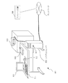
図1は、コンピュータにより実現するシステム構成管理方式101の外観の一例を示す図である。図1において、システム構成管理方式101は、システムユニット830、CRT(Cathode Ray Tube)やLCD(液晶)の表示画面を有する表示装置813、キーボード814(Key Board:K/B)、マウス815、FDD817(Flexible Disk Drive)、コンパクトディスク装置818(CDD:Compact Disk Drive)、プリンタ装置819などのハードウェア資源を備え、これらはケーブルや信号線で接続されている。
FIG. 1 is a diagram showing an example of the appearance of a system
システムユニット830は、コンピュータであり、また、ネットワークに接続されている。ネットワークには、ストレージ装置500に接続されている。後述するCIテーブル記憶部、対応テーブル記憶部、関係モデル登録部などは、ネットワークに接続されたストレージ装置500により実現しても構わないし、また、システムユニット830に内蔵された磁気ディスク装置により実現されても構わない。システム構成管理方式101は、ネットワークを介してストレージ装置500と通信可能である。
The system unit 830 is a computer and is connected to a network. The network is connected to the
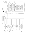
図2は、実施の形態1におけるシステム構成管理方式101のハードウェア資源の一例を示す図である。実施の形態2〜実施の形態4のシステム構成管理方式も同様の構成である。図2において、システム構成管理方式101は、プログラムを実行するCPU810(中央処理装置、処理装置、演算装置、マイクロプロセッサ、マイクロコンピュータ、プロセッサともいう)を備えている。CPU810は、バス825を介してROM(Read Only Memory)811、RAM(Random Access Memory)812、表示装置813、キーボード814、マウス815、通信ボード816、FDD817、CDD818、プリンタ装置819、磁気ディスク装置820と接続され、これらのハードウェアデバイスを制御する。磁気ディスク装置820の代わりに、光ディスク装置、メモリカード読み書き装置などの記憶装置でもよい。
FIG. 2 is a diagram illustrating an example of hardware resources of the system
RAM812は、揮発性メモリの一例である。ROM811、FDD817、CDD818、磁気ディスク装置820等の記憶媒体は、不揮発性メモリの一例である。これらは、記憶装置あるいは記憶部、格納部の一例である。通信ボード816、キーボード814、FDD817などは、入力部、入力装置の一例である。また、通信ボード816、表示装置813、プリンタ装置819などは、出力部、出力装置の一例である。
The
通信ボード816は、ネットワークに接続されている。通信ボード816は、インターネット、ISDN等のWAN(ワイドエリアネットワーク)などに接続されていても構わない。
The
磁気ディスク装置820には、オペレーティングシステム821(OS)、ウィンドウシステム822、プログラム群823、ファイル群824が記憶されている。プログラム群823のプログラムは、CPU810、オペレーティングシステム821、ウィンドウシステム822により実行される。
The
上記プログラム群823には、以下に述べる実施の形態の説明において「〜部」として説明する機能を実行するプログラムが記憶されている。プログラムは、CPU810により読み出され実行される。
The
ファイル群824には、以下に述べる実施の形態の説明において、「〜の生成結果」、「〜の変更結果」、「〜の処理結果」として説明する情報や、データや信号値や変数値やパラメータなど、あるいは「CIテーブル」、「対応テーブル」、「関係モデル」、「関係情報」などが、「〜ファイル」や「〜データベース」の各項目として記憶されている。「〜ファイル」や「〜データベース」は、ディスクやメモリなどの記録媒体に記憶される。ディスクやメモリなどの記憶媒体に記憶された情報やデータや信号値や変数値やパラメータは、読み書き回路を介してCPU810によりメインメモリやキャッシュメモリに読み出され、抽出・検索・参照・比較・演算・計算・処理・出力・印刷・表示などのCPUの動作に用いられる。抽出・検索・参照・比較・演算・計算・処理・出力・印刷・表示のCPUの動作の間、情報やデータや信号値や変数値やパラメータは、メインメモリやキャッシュメモリやバッファメモリに一時的に記憶される。
The
また、以下に述べる実施の形態の説明においては、データや信号値は、RAM812のメモリ、FDD817のフレキシブルディスク、CDD818のコンパクトディスク、磁気ディスク装置820の磁気ディスク、その他光ディスク、ミニディスク、DVD(Digital Versatile Disk)等の記録媒体に記録される。また、データや信号は、バス825や信号線やケーブルその他の伝送媒体によりオンライン伝送される。
In the description of the embodiments described below, data and signal values are stored in the memory of
また、以下に述べる実施の形態の説明において「〜部」として説明するものは、「〜回路」、「〜装置」、「〜機器」、「手段」であってもよく、また、「〜ステップ」、「〜手順」、「〜処理」であってもよい。すなわち、「〜部」として説明するものは、ROM811に記憶されたファームウェアで実現されていても構わない。或いは、ソフトウェアのみ、或いは、素子・デバイス・基板・配線などのハードウェアのみ、或いは、ソフトウェアとハードウェアとの組み合わせ、さらには、ファームウェアとの組み合わせで実施されても構わない。ファームウェアとソフトウェアは、プログラムとして、磁気ディスク、フレキシブルディスク、光ディスク、コンパクトディスク、ミニディスク、DVD等の記録媒体に記憶される。プログラムはCPU810により読み出され、CPU810により実行される。すなわち、プログラムは、以下に述べる「〜部」としてコンピュータを機能させるものである。あるいは、以下に述べる「〜部」の手順や方法をコンピュータに実行させるものである。
In addition, what is described as “to part” in the description of the embodiment described below may be “to circuit”, “to device”, “to device”, “means”, and “to step”. ”,“ ˜procedure ”, or“ ˜processing ”. That is, what is described as “˜unit” may be realized by firmware stored in the
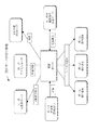
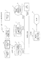
図3は、実施の形態1におけるシステム構成管理方式101の構成を示すブロック図である。システム構成管理方式101は、構成要素情報登録部1、CIと関係モデルの対応付け部2(対応関係生成部)、関係モデル作成部3、CIテーブル記憶部4(構成要素情報記憶部)、CIと関係モデルの対応テーブル記憶部5(対応情報記憶部)、関係モデル登録部6、関係情報生成部7、生成指示部8、構成管理データベース9(関係情報記憶部)、表示部10とを備える。
FIG. 3 is a block diagram illustrating a configuration of the system
CIテーブル記憶部4は、CIテーブル41(構成要素情報)を格納する。「CIテーブル41」は、システムに存在するCI(Configuration Item:構成要素)を列挙するテーブルであり、「構成要素情報登録部1」により登録される。「CIテーブル41」により、システムに存在する構成要素の個々を特定可能である。以下では構成要素を「CI」と表記する場合がある。
The CI
「CIと関係モデルの対応テーブル記憶部5」は、「CIと関係モデルの対応テーブル51」(以下、対応テーブルという)を格納する。
The “CI and relational model correspondence
関係モデル登録部6は、関係モデルを記憶する関係モデル記憶部61を備える。
The relationship
各構成要素の機能を説明する。
(1)構成要素情報登録部1は、構成要素をCIテーブル記憶部4のCIテーブル41に登録する。
(2)CIテーブル記憶部4は、CIテーブル41を記憶しており、CIテーブル41に所定のシステムに存在する複数の構成要素を記憶する。
(3)関係モデル作成部3は、後述の「関係モデル」を作成する。ここで、「関係モデル」とは、管理の対象となるシステムに存在する構成要素の種別ごとに定義され、かつ、前記種別に係る構成要素が他の構要素とどのような関係を持つのかを表すモデルである。図9のS12で後述するが、関係モデル作成部3がユーザによる操作を介して関係モデルを作成する。
(4)関係モデル登録部6は、関係モデル作成部3により作成された関係モデルの登録を受け付け、関係モデルを関係モデル記憶部61に記憶する。
(5)「CIと関係モデルの対応付け部2」は、CIテーブル記憶部4のCIテーブル41に記憶された複数の構成要素のそれぞれに関係モデル記憶部61が記憶した関係モデルのいずれかを対応付けることにより対応関係を生成する。そして、生成した対応関係を「CIと関係モデルの対応テーブル記憶部5」に対応テーブル(対応情報)51として記憶させる。
(6)「CIと関係モデルの対応テーブル記憶部5」は、対応テーブル51を記憶している。対応テーブル51は、個々のCIがどの「関係クラス」に対応するかの情報を保持するテーブルであり「CIと関係モデルの対応付け部2」により登録される。
(7)関係情報生成部7は、CIテーブル41と、関係モデル記憶部61に登録された複数の関係モデルと、対応テーブル51とを参照することにより、「関係情報」を生成する。
「関係情報」とは、システムに存在する複数の構成要素のそれぞれを特定可能であるとともに前記システムに存在する複数の構成要素のそれぞれが他の構成要素とどのような関係を持つのかを示す情報である。関係情報生成部7は、生成した関係情報を「構成管理データベース9」に登録する。関係情報生成部7は、「生成指示部8」からの生成指示信号により動作する。
(8)構成管理データベース9は、関係情報生成部7が生成した関係情報を保管する。
The function of each component will be described.
(1) The component element
(2) The CI
(3) The relation
(4) The relation
(5) The “CI and relational
(6) The “CI and relation model correspondence
(7) The relationship
"Relational information" is information that can identify each of a plurality of components existing in the system and indicates what relationship each of the plurality of components existing in the system has with other components. It is. The relationship
(8) The
次に、図4〜図9を用いて、システム構成管理方式101の動作を説明する。
Next, the operation of the system
図4は、「支店サーバ」というサーバが持つ他の構成要素との間の関係を示す情報の例である。図4は、関係情報生成部7が生成する関係情報の元となる概念的な関係を示す図である。これに対して後述の図10は、関係情報生成部7が電子データとして生成する具体的な情報である。
FIG. 4 is an example of information indicating a relationship between other components of the “branch server” server. FIG. 4 is a diagram illustrating a conceptual relationship that is a source of the relationship information generated by the relationship
図5は、図4の「支店サーバ」について表した「関係モデル」の例である。図4の「支店サーバ」についての「関係モデル」のモデルIDは「Model−01」である。図5では、「支店サーバ」と他のCI(構成要素)との間の関係線を「関係クラス」として表現し、
メソッド「関係CI( )」
に具体的な支店サーバの情報を与えることにより、具体的な関係相手のCIが何であるかを得ることができる。
メソッド「関係CI( )」
の実装方法は任意の方法を採用してよい。
FIG. 5 is an example of a “relationship model” representing the “branch server” in FIG. The model ID of “Relational Model” for “Branch Server” in FIG. 4 is “Model-01”. In FIG. 5, the relationship line between the “branch server” and another CI (component) is expressed as a “relation class”.
Method "Relationship CI ()"
By giving specific branch server information to, it is possible to obtain what is the CI of the specific related party.
Method "Relationship CI ()"
Any method may be adopted as the mounting method.
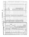
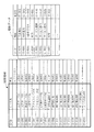
図6は、「CIテーブル41」へのデータ登録の例を示す図である。「CIテーブル41」は、「CI−ID」、「CI名称」及び「属性」を含む。なお、図6におけるUNIX(登録商標)、Linux(登録商標)、WINDOWS(登録商標)は、OS(オペレーティングシステム)を示す。 FIG. 6 is a diagram illustrating an example of data registration in the “CI table 41”. The “CI table 41” includes “CI-ID”, “CI name”, and “attribute”. Note that UNIX (registered trademark), Linux (registered trademark), and WINDOWS (registered trademark) in FIG. 6 indicate OS (operating system).
ここで、図5、図6を参照して、「関係モデル」及び「関係情報」を更に詳しく説明する。 Here, with reference to FIGS. 5 and 6, the “relation model” and the “relation information” will be described in more detail.
(1.関係モデル)
「関係モデル」は、個々の実物(現物)を特定せずに「○○というものは、△△というものと□□の関係を持っている」のような関係を示しているモデルである。図5に示す関係モデルでは、例えば、各支店の「支店サーバ」というものは、「同じ支店に設置されているアクセスルータというもの」と「外部通信で(支店サーバがアクセスルータを)利用する」という関係を持っていること、を示している。「関係モデル」では、個々の現物を識別していない。関係モデルでは、例えば、「丸の内支店の支店サーバ」か「横浜支店の支店サーバ」かを区別せず、どこの支店であれ「支店サーバというものは××である」ということを示している。
(1. Relational model)
The “relationship model” is a model that shows a relationship such as “the thing of XX has a relation of △△ and □□” without specifying each actual thing (actual thing). In the relationship model shown in FIG. 5, for example, “branch server” of each branch is “access router installed in the same branch” and “external communication (branch server uses access router)” It has shown that it has the relationship. The “relationship model” does not identify individual objects. In the relational model, for example, “branch server is xx” regardless of the branch, without distinguishing between “branch server of Marunouchi branch” and “branch server of Yokohama branch”.
(2.関係情報)
これに対して図10で後述する「関係情報」は、個々の現物に関する関係の情報である。例えば、図6のCIテーブル41において
「CI−ID=CI−0001」
を持つ丸の内支店サーバ(図6のロケーションの支店001を丸の内支店と仮定した)は、
「CI−ID=CI−0012」
を持つ
「丸の内支店に設置のアクセスルータ」
と、外部通信で利用、という関係を持つ」という具体情報である。
(2. Related information)
On the other hand, “relation information”, which will be described later with reference to FIG. For example, “CI-ID = CI-0001” in the CI table 41 of FIG.
The Marunouchi branch server (assuming that the branch 001 in the location of FIG. 6 is a Marunouchi branch)
“CI-ID = CI-0012”
"Access router installed in Marunouchi branch"
And is used in external communication.
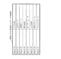
図7は、「関係モデル登録部6」へのデータ登録例である。図5と図7との内容が「関係モデル登録部6」の関係モデル記憶部61に記憶される。
FIG. 7 shows an example of data registration in the “relationship
図8は、「対応テーブル51」へのデータ登録例を示す図である。 FIG. 8 is a diagram illustrating an example of data registration in the “correspondence table 51”.
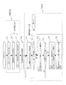
図9は、システム構成管理方式101による処理フローを示している。フロー内の「丸囲み番号」は、図3の「丸囲み番号」に対応する。
FIG. 9 shows a processing flow according to the system
次に、図9を参照してシステム構成管理方式101の動作を説明する。
Next, the operation of the system
(準備作業)
まず、ユーザが準備作業を行う(S11〜S13)。
(1)ユーザが構成要素情報登録部1により管理対象であるシステム内に存在するCIをCIテーブル41に登録する(S11、丸1)。
(2)次に、ユーザが「関係モデル作成部3」によりCIの種別毎に「関係モデル」を作成し、「関係モデル」を関係モデル記憶部61に登録する(S12、丸2)。
(3)次に、ユーザは、「CIと関係モデルの対応付け部2」により「CIテーブル41」に登録されている個々のCIについて「関係モデル」を対応付け、対応テーブル51を生成する(S13、丸3)。ここまでが準備作業となる。
(preparation work)
First, the user performs preparatory work (S11 to S13).
(1) The user registers the CI existing in the system to be managed by the component
(2) Next, the user creates a “relation model” for each CI type using the “relation
(3) Next, the user associates the “related model” with each CI registered in the “CI table 41” by the “CI and related
(関係情報生成部7による関係情報の生成:自動化)
関係情報生成部7は、生成指示部8が出力する生成指示信号を入力することより関係情報を生成する処理を開始する(S14、丸4)。
(Generation of relationship information by the relationship information generation unit 7: automation)
The relationship
まず、関係情報生成部7は、図6に示す「対応テーブル51」からCIと関係モデルの対を1つ取得する(S15、丸5−1)。
例えば、
「CI−ID=CI−0001」と「Model−ID=Model−01」
の対を一つ取得する。
First, the relationship
For example,
“CI-ID = CI-0001” and “Model-ID = Model-01”
Get one pair.
次に、CI−0001(丸の内支店サーバであるとする)は、「他のCI」とどのような関係を持っているのかを具体化する必要がある。関係情報生成部7は、取得した対における関係モデルが定義している関係クラスを1つ特定する(S17、丸5−2)。例えば、関係情報生成部7は、支店サーバの「関係モデル」を参照し、「支店サーバ」という箱は、「アクセスルータ」という箱と線が繋がっているので、「丸の内支店サーバ」は「アクセスルータ」というものと関係があることを確認する。次に、関係情報生成部7は、CI−0001(丸の内支店サーバ)が具体的にどのアクセスルータとどのような関係があるかを特定する必要がある。それを特定するために、関係情報生成部7は、「関係モデル」において「支店サーバ」の箱と「アクセルルータ」の箱とを繋いでいる線にひもづいている「関係クラス」を利用する。この関係クラスは、「どういう関係か」の情報と、「相手を具体的に特定するメソッド(関数)」とを持っている。「どういう関係か」については「関係モデル」により、「外部通信(で利用)」という関係であることがわかる。ここで、関係情報生成部7は、「具体的な関係相手」については、メソッドを使って情報を得る。関係クラスが持っているメソッド「関係CI( )」に「丸の内支店の支店サーバ」の情報(CI−ID=CI−0001)を与えると、メソッドは、「丸の内支店のアクセスルータ」が具体的な相手であることを返す。「〜メソッド」の実装については言及していない。例えば、この例で言えば、
(a)与えられたCI−IDの設置場所(ロケーション)を「CIテーブル」表から検索する。
(b)同じ設置場所のアクセスルータを「CIテーブルから」検索する。
(c)そのアクセスルータのCI−IDを取得してメソッドの返り値とする、のような処理が実行される。
(S19、丸5−3)。
Next, CI-0001 (assuming it is a Marunouchi branch server) needs to specify what kind of relationship it has with “another CI”. The relationship
(A) The installation location (location) of the given CI-ID is searched from the “CI table” table.
(B) Search the access router at the same installation location “from the CI table”.
(C) Processing such as acquiring the CI-ID of the access router and using it as the return value of the method is executed.
(S19, circle 5-3).
関係相手CIとの間に図10で後述する「関係データ」を設定し、この「関係データ」を「構成管理データベース9」に登録する(S20、丸5−4)。
“Relational data” described later in FIG. 10 is set with the related party CI, and this “relational data” is registered in the “
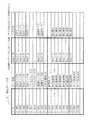
関係情報生成部7は、この処理を関係モデル記憶部61が記憶する「関係モデル」が定義している全関係クラスについて実行し、さらに「対応テーブル51」に登録される全CIについて処理を終えるまで繰り返す。図10は、関係情報生成部7の処理により生成される「関係情報」の例である。図10では、「CI−0001」(支点サーバ01)に関する8個の「関係データ」を生成し登録している場合を示している。
The relationship
実施の形態1のシステム構成管理方式101は関係情報生成部7を備えたので、システム構成管理における「関係情報」の作成を行う際に、管理者(ユーザ)が手作業で個々のCIを選定して関係情報を登録する必要がなく、関係情報を自動的に生成し登録することができる。このため、作業負荷を軽減できるとともに、作業ミスによる誤登録を削減することができる。
Since the system
実施の形態2.
次に図11を用いて実施の形態2を説明する。実施の形態1では、「関連情報」の初期登録のケースを示した。実施の形態2では、CIを新たに追加したり削除したりする変更があった場合の、「関係情報」の更新に関する実施形態を示す。
Next,
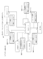
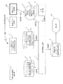
図11は、実施の形態2におけるシステム構成管理方式102のブロック構成図である。システム構成管理方式102は、図3のシステム構成管理方式101の構成に対して、「構成要素情報変更部201」を加えた構成である。構成要素情報変更部201は、CIテーブル41を参照し、CIを追加したり削除したり変更したりする機能を持つ。
FIG. 11 is a block configuration diagram of the system configuration management method 102 according to the second embodiment. The system configuration management method 102 is a configuration obtained by adding a “configuration element
動作の概要を説明する。
(1)構成要素情報変更部201は、CIテーブル41を変更する。
(2)生成指示部8は、関係情報生成部7に対して関係情報の再生成を指示する再生成指示信号を出力する。
(3)関係情報生成部7は、構成要素情報変更部201によりCIテーブルが変更された場合において生成指示部8から再生成指示信号を入力すると、変更後のCIテーブルに基づいて関係情報を再生成し、構成管理データベースに登録する。
An outline of the operation will be described.
(1) The component element
(2) The
(3) When the reconfiguration instruction signal is input from the
実際のシステムでのCIの変更に伴い、構成管理データベース9内の関係情報を含む構成情報を更新する必要があるが、実施の形態2のシステム構成管理方式102は、構成要素情報変更部201を備えたので、CIテーブル41の更新を行い、生成指示部8から関係情報生成部7に再生成指示信号を送信するのみで、関係情報の更新を行うことができる。このため、個々のCIを選定してのデータ更新作業は必要無く、作業負荷を軽減できるとともに、作業ミスによる誤更新を削減できる。
With the change of the CI in the actual system, it is necessary to update the configuration information including the relationship information in the
実施の形態3.
図12を用いて実施の形態3を説明する。実施の形態1では、「関連情報」の初期登録のケースを示した。実施の形態3では、業務システムの内部構成が変わった等の「モデル変更」があった場合の、関係情報の更新に関する実施形態を示す。
The third embodiment will be described with reference to FIG. In the first embodiment, the case of initial registration of “related information” is shown. In the third embodiment, an embodiment relating to the update of relation information when there is a “model change” such as a change in the internal configuration of the business system will be described.
図12は、実施の形態3におけるシステム構成管理方式103のブロック構成図である。システム構成管理方式103は、図3のシステム構成管理方式101の構成に対して「関係モデル変更部301」を設けた構成である。「関係モデル変更部301」は、「関係モデル登録部6」の関係モデル記憶部61を参照し、関係モデルを変更する機能を持つ。
FIG. 12 is a block configuration diagram of the system configuration management method 103 according to the third embodiment. The system configuration management method 103 is a configuration in which a “relationship
動作の概要を説明する。
(1)関係モデル変更部301が、関係モデル記憶部61に記憶された関係モデルを変更する。
(2)生成指示部8は、関係情報生成部7に対して関係情報の再生成を指示する再生成指示信号を出力する。
(3)関係情報生成部7は、関係モデル変更部301により関係モデルのいずれかが変更された場合において生成指示部8から再生成指示信号を入力すると、変更後の関係モデルに基づいて関係情報を再生成する。
An outline of the operation will be described.
(1) The relation
(2) The
(3) The relationship
関係モデルの変更に伴い、構成管理データベース9内の関係情報を含む構成情報を更新する必要があるが、実施の形態3のシステム構成管理方式103は、関係モデル変更部301を備えたので、関係モデル記憶部61に記憶された関係モデルの更新を可能とし、生成指示部8から関係情報生成部7に再生成指示信号を送信するのみで関係情報の更新を行うことができる。このため、個々のCIを選定してのデータ更新作業は必要無く、作業負荷を軽減できるとともに、作業ミスによる誤更新を削減できる。
With the change of the relationship model, it is necessary to update the configuration information including the relationship information in the
実施の形態4.
次に図13を用いて実施の形態4を説明する。実施の形態1では、「関連情報」の初期登録のケースを示した。実施の形態4では、既存のサーバの用途を変更したり、あるいは新たな機能を導入した場合等、「CIと関係モデルの対応」に変更があった場合の、関係情報の更新に関する実施形態を示す。
Next,
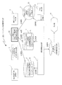
図13は、実施の形態4におけるシステム構成管理方式104のブロック構成図である。システム構成管理方式104は、図3のシステム構成管理方式101の構成に対して、「CIと関係モデルの対応付け変更部401」(対応情報変更部)を加えた構成である。「CIと関係モデルの対応付け変更部401」は、対応テーブル51を参照し、「CIと関係モデルの対応関係」を変更する機能を持つ。
FIG. 13 is a block configuration diagram of the system configuration management method 104 according to the fourth embodiment. The system configuration management method 104 is a configuration obtained by adding a “CI and relationship model
動作の概要を説明する。
(1)「CIと関係モデルの対応付け変更部401」は、対応テーブルを変更する。
(2)生成指示部8は、関係情報生成部7に対して関係情報の再生成を指示する再生成指示信号を出力する。
(3)関係情報生成部7は、「CIと関係モデルの対応付け変更部401」により対応テーブル51が変更された場合において生成指示部8から再生成指示信号を入力すると、変更後の対応テーブルに基づいて関係情報を再生成する。
An outline of the operation will be described.
(1) The “CI and relational model
(2) The
(3) When the correspondence table 51 is changed by the “CI and relational model
なお、実施の形態2〜実施の形態4で述べたように、システムの変更には様々なケースがある。
(1)CI自体の属性が変わるケースでは、「CIテーブル」を変更する(実施の形態2)。例えば、サーバの役割も接続形態も何も変わらないけれども、OS(オペレーションシステム)のバージョンアップをしたような場合である。
(2)関係モデルが変わるケースでは、「関係モデル」の定義を変更する(実施の形態3)。例えば、全部支店の「支店サーバ」が(サーバの属性等は何も変わらないけれども)、それまでは「アクセスルータ」を経由して回線Aで繋がっていたが、「ブロードバンドルータ」に接続して回線Bに繋ぐように変えたような場合である。
(3)CIと関係モデルの対応が変わるケースでは、「対応テーブル」を変更する(実施の形態4)。例えば、丸の内支店の「支店サーバ」を(サーバの名前やCI−IDを変えないけれども)使い方を全く変更して、支店内の「プリンターサーバ」に変更する場合には、それまでCI−0001は「支店サーバ」と対応づいていたところを、CI−0001は「プリンターサーバ」という関係モデルに対応づくように変更する必要がある。「プリンターサーバ」モデルは既に定義されていたと想定)。このケースでは、CIテーブルも、関係モデルも変更がない。
As described in
(1) In the case where the attribute of the CI itself changes, the “CI table” is changed (second embodiment). For example, the role of the server and the connection form are not changed, but the OS (operation system) is upgraded.
(2) In the case where the relational model changes, the definition of “relational model” is changed (third embodiment). For example, the “branch server” of all branches (although the server attributes etc. do not change anything), until then it was connected by the line A via the “access router”, but connected to the “broadband router” This is a case where the connection is changed to connect to the line B.
(3) In the case where the correspondence between the CI and the relational model changes, the “correspondence table” is changed (Embodiment 4). For example, if the usage of the “branch server” of the Marunouchi branch is changed completely (although the server name and the CI-ID are not changed) and changed to the “printer server” in the branch, then the CI-0001 The CI-0001 needs to be changed so as to correspond to the relation model of “printer server” where it corresponds to the “branch server”. It is assumed that the “Printer Server” model has already been defined). In this case, neither the CI table nor the relational model is changed.
「CIと関係モデルの対応」の変更に伴い、構成管理データベース9内の関係情報を含む構成情報を更新する必要があるが、実施の形態4のシステム構成管理方式104は、「CIと関係モデルの対応付け変更部401」を備えたので、「CIと関係モデルの対応」の更新を行い、生成指示部8から関係情報生成部7に再生成指示信号を送信するのみで、関係情報の更新を行うことができる。このため、個々のCIを選定してのデータ更新作業は必要無く、作業負荷を軽減できるとともに、作業ミスによる誤更新を削減できる。
With the change of “correspondence between CI and relationship model”, it is necessary to update the configuration information including the relationship information in the
実施の形態5.
実施の形態5は、実施の形態1で説明したシステム構成管理方式をコンピュータに実行させる実施形態である。図3におけるシステム構成管理方式101の各構成要素の動作は互いに関連しており、各構成要素の動作を、コンピュータに実行させるシステム管理プログラムとして把握することができる。
すなわち、図3におけるシステム構成管理方式101の各構成要素の動作は、
所定のシステムに存在する複数の構成要素の個々を特定可能な構成要素情報を記憶する処理と、
前記システムに存在する構成要素の種別ごとに定義され、かつ、前記種別に係る構成要素が他の構成要素とどのような関係を持つのかを表す関係モデルを種別ごとに記憶する処理と、
構成要素情報として記憶した複数の構成要素のそれぞれに記憶した関係モデルのいずれかが対応付けられている対応情報を記憶する処理と、
記憶した構成要素情報と、記憶した種別ごとの関係モデルと、記憶した対応情報とを参照することにより、前記システムに存在する複数の構成要素のそれぞれを特定可能であるとともに前記システムに存在する複数の構成要素のそれぞれが他の構成要素とどのような関係を持つのかを示す関係情報を生成する処理と、
生成した関係情報を記憶する処理と
をコンピュータに実行させるシステム構成管理プログラムとして把握することができる。
The fifth embodiment is an embodiment in which a computer executes the system configuration management method described in the first embodiment. The operations of the components of the system
That is, the operation of each component of the system
A process of storing component information that can identify each of a plurality of components existing in a predetermined system;
A process for storing, for each type, a relational model that is defined for each type of component existing in the system and that expresses what kind of relationship the component related to the type has with other components;
A process of storing correspondence information associated with any of the relational models stored in each of the plurality of constituent elements stored as the constituent element information;
By referring to the stored component information, the stored relationship model for each type, and the stored correspondence information, each of a plurality of components existing in the system can be specified and a plurality of existing in the system Processing to generate relationship information indicating how each of the components has a relationship with other components;
It can be grasped as a system configuration management program for causing a computer to execute processing for storing the generated relationship information.
以上の実施の形態では、以下の手段を備えたシステム構成情報管理方式であって、
(a)システム構成要素情報(以降CIと表示する場合あり=Configuration Item)を保管する手段
(b)個々の構成要素種別毎の「構成要素間の関係情報モデル」(以降「関係モデル」)
を保管する手段
(c)個々の構成要素と関係モデルを対応づける手段(対応づけ結果は(a)に保管)
(d)構成要素情報と関係モデルを利用して個々の構成要素についての関係情報を
生成する手段
(e)(d)で生成した関係情報を含む構成情報を保管する手段
(f)(e)の構成情報を表示する手段
(b)の関係モデルを利用して構成要素間の関係情報を生成するシステム構成管理方式を説明した。
In the above embodiment, a system configuration information management method comprising the following means,
(A) Means for storing system component information (hereinafter may be displayed as CI = Configuration Item) (b) “Relationship information model between configuration elements” for each component type (hereinafter “relation model”)
(C) means for associating individual components with relational models (correspondence results are stored in (a))
(D) Means for generating relation information for each constituent element using the constituent element information and the relation model (e) Means for storing the constituent information including the relation information generated in (d) (f) (e) The system configuration management method for generating the relationship information between the components using the relationship model of the means (b) for displaying the configuration information has been described.
以上の実施の形態では、以下の手段をあわせもつシステム構成管理方式であって、
(g)構成要素の情報を参照し編集できる手段
(h)関係情報生成処理を再実行させる手段
システム構成要素の追加設置、撤去等の変更時に、構成情報の中の関係情報を更新できるシステム構成管理方式を説明した。
In the above embodiment, the system configuration management method has the following means,
(G) Means capable of referencing and editing information on component elements (h) Means for re-executing relation information generation processing System configuration capable of updating relation information in configuration information upon change of addition / removal of system component elements Explained the management method.
以上の実施の形態では、以下の手段をあわせもつシステム構成管理方式であって、
(j)関係モデルの情報を表示し編集できる手段
(k)関係情報生成処理を再実行させる手段
システム構成要素の機能変更や業務システムの連携サーバの変更等の関係情報の変更時に、構成情報の中の関係情報を更新できるシステム構成管理方式を説明した。
In the above embodiment, the system configuration management method has the following means,
(J) Means for displaying and editing relation model information (k) Means for re-executing relation information generation processing When changing relation information such as a function change of a system component or a change of a linkage server of a business system, Explained the system configuration management method that can update the related information.
以上の実施の形態では、以下の手段をあわせもつシステム構成管理方式であって、
(m)関係モデルと構成要素の対応情報を参照し編集できる手段
(n)関係情報生成処理を再実行させる手段
システム構成要素の役割変更の場合等に、構成情報の中の関係情報を更新できるシステム構成管理方式を説明した。
In the above embodiment, the system configuration management method has the following means,
(M) Means capable of referencing and editing correspondence information between relation model and constituent element (n) Means for re-executing relation information generation processing Relation information in the constituent information can be updated in the case of a role change of the system constituent element The system configuration management method was explained.
1 構成要素情報登録部、2 CIと関係モデルの対応付け部、3 関係モデル作成部、4 CIテーブル記憶部、5 CIと関係モデルの対応テーブル記憶部、6 関係モデル登録部、7 関係情報生成部、8 生成指示部、9 構成管理データベース、10 表示部、41 CIテーブル、51 対応テーブル、61 関係モデル記憶部、101,102,103,104 システム構成管理方式、201 構成要素情報変更部、301 関係モデル変更部、401 CIと関係モデルの対応付け変更部、500 ストレージ装置、810 CPU、811 ROM、812 RAM、813 表示装置、814 K/B、815 マウス、816 通信ボード、817 FDD、818 CDD、819 プリンタ装置、820 磁気ディスク装置、821 OS、822 ウィンドウシステム、823 プログラム群、824 ファイル群、825 バス、830 システムユニット。
DESCRIPTION OF
Claims (6)
前記システムに存在する構成要素の種別ごとに定義され、かつ、前記種別に係る構成要素が他の構成要素とどのような関係を持つのかを表す関係モデルを種別ごとに記憶する関係モデル記憶部と、
前記構成要素情報記憶部が構成要素情報として記憶した複数の構成要素のそれぞれに前記関係モデル記憶部が記憶した関係モデルのいずれかが対応付けられている対応情報を記憶する対応情報記憶部と、
前記構成要素情報記憶部が記憶した構成要素情報と、前記関係モデル記憶部が記憶した種別ごとの関係モデルと、前記対応情報記憶部が記憶した対応情報とを参照することにより、前記システムに存在する複数の構成要素のそれぞれを特定可能であるとともに前記システムに存在する複数の構成要素のそれぞれが他の構成要素とどのような関係を持つのかを示す関係情報を生成する関係情報生成部と、
前記関係情報生成部が生成した関係情報を記憶する関係情報記憶部と
を備えたことを特徴とするシステム構成管理方式。 A component information storage unit that stores component information capable of specifying each of a plurality of components existing in a predetermined system;
A relational model storage unit that is defined for each type of component existing in the system and stores a relational model for each type indicating a relationship between the component related to the type and another component; ,
A correspondence information storage unit that stores correspondence information in which any of the relational models stored by the relational model storage unit is associated with each of a plurality of constituent elements stored as the constituent element information by the constituent element information storage unit;
By referring to the component element information stored in the component element information storage unit, the relationship model for each type stored in the relationship model storage unit, and the correspondence information stored in the correspondence information storage unit, the system exists. Each of a plurality of constituent elements that can be identified and a relation information generation unit that generates relation information indicating how each of the plurality of constituent elements existing in the system has other constituent elements;
A system configuration management system comprising: a relationship information storage unit that stores the relationship information generated by the relationship information generation unit.
前記構成要素情報記憶部が構成要素情報として記憶した複数の構成要素のそれぞれに前記関係モデル記憶部が記憶した関係モデルのいずれかを対応付けることにより対応関係を生成し、生成した対応関係を前記対応情報記憶部に対応情報として記憶させる対応関係生成部を備えたことを特徴とする請求項1記載のシステム構成管理方式。 The system configuration management method further includes:
A correspondence relationship is generated by associating one of the relationship models stored in the relationship model storage unit with each of the plurality of component elements stored as the component element information in the component element information storage unit, and the generated correspondence relationship is the correspondence The system configuration management system according to claim 1, further comprising a correspondence generation unit that is stored as correspondence information in the information storage unit.
前記構成要素情報記憶部が記憶した構成要素情報を変更する構成要素情報変更部を備え、
前記関係情報生成部は、
前記構成要素情報変更部により前記構成要素情報が変更された場合には、変更後の構成要素情報に基づいて関係情報を再生成することを特徴とする請求項1記載のシステム構成管理方式。 The system configuration management method further includes:
A component information changing unit that changes the component information stored in the component information storage unit;
The relationship information generation unit
The system configuration management method according to claim 1, wherein when the component element information is changed by the component element information changing unit, the relationship information is regenerated based on the changed component element information.
前記関係モデル記憶部が記憶した関係モデルを変更する関係モデル変更部を備え、
前記関係情報生成部は、
前記関係モデル変更部により関係モデルのいずれかが変更された場合には、変更後の関係モデルに基づいて関係情報を再生成することを特徴とする請求項1記載のシステム構成管理方式。 The system configuration management method further includes:
A relational model changing unit for changing the relational model stored in the relational model storage unit;
The relationship information generation unit
2. The system configuration management system according to claim 1, wherein when any of the relational models is changed by the relational model changing unit, the relation information is regenerated based on the changed relation model.
前記対応情報記憶部が記憶した対応情報を変更する対応情報変更部を備え、
前記関係情報生成部は、
前記対応情報変更部により対応情報が変更された場合には、変更後の対応情報に基づいて関係情報を再生成することを特徴とする請求項1記載のシステム構成管理方式。 The system configuration management method further includes:
A correspondence information changing unit for changing the correspondence information stored in the correspondence information storage unit;
The relationship information generation unit
2. The system configuration management system according to claim 1, wherein when the correspondence information is changed by the correspondence information changing unit, the relationship information is regenerated based on the changed correspondence information.
前記システムに存在する構成要素の種別ごとに定義され、かつ、前記種別に係る構成要素が他の構成要素とどのような関係を持つのかを表す関係モデルを種別ごとに記憶する処理と、
構成要素情報として記憶した複数の構成要素のそれぞれに記憶した関係モデルのいずれかが対応付けられている対応情報を記憶する処理と、
記憶した構成要素情報と、記憶した種別ごとの関係モデルと、記憶した対応情報とを参照することにより、前記システムに存在する複数の構成要素のそれぞれを特定可能であるとともに前記システムに存在する複数の構成要素のそれぞれが他の構成要素とどのような関係を持つのかを示す関係情報を生成する処理と、
生成した関係情報を記憶する処理と
をコンピュータに実行させることを特徴とするシステム構成管理プログラム。 A process of storing component information that can identify each of a plurality of components existing in a predetermined system;
A process for storing, for each type, a relational model that is defined for each type of component existing in the system and that expresses what kind of relationship the component related to the type has with other components;
A process of storing correspondence information associated with any of the relational models stored in each of the plurality of constituent elements stored as the constituent element information;
By referring to the stored component information, the stored relationship model for each type, and the stored correspondence information, each of a plurality of components existing in the system can be specified and a plurality of existing in the system Processing to generate relationship information indicating how each of the components has a relationship with other components;
A system configuration management program that causes a computer to execute processing for storing generated relational information.
Priority Applications (1)
| Application Number | Priority Date | Filing Date | Title |
|---|---|---|---|
| JP2006181519A JP2008009861A (en) | 2006-06-30 | 2006-06-30 | System configuration management method |
Applications Claiming Priority (1)
| Application Number | Priority Date | Filing Date | Title |
|---|---|---|---|
| JP2006181519A JP2008009861A (en) | 2006-06-30 | 2006-06-30 | System configuration management method |
Publications (1)
| Publication Number | Publication Date |
|---|---|
| JP2008009861A true JP2008009861A (en) | 2008-01-17 |
Family
ID=39067986
Family Applications (1)
| Application Number | Title | Priority Date | Filing Date |
|---|---|---|---|
| JP2006181519A Pending JP2008009861A (en) | 2006-06-30 | 2006-06-30 | System configuration management method |
Country Status (1)
| Country | Link |
|---|---|
| JP (1) | JP2008009861A (en) |
Cited By (7)
| Publication number | Priority date | Publication date | Assignee | Title |
|---|---|---|---|---|
| JP2009217463A (en) * | 2008-03-10 | 2009-09-24 | Fujitsu Ltd | Information processor, information processing program, and method |
| WO2009157062A1 (en) * | 2008-06-25 | 2009-12-30 | 富士通株式会社 | Configuration management device, configuration management program, and configuration management method |
| JP2011197808A (en) * | 2010-03-17 | 2011-10-06 | Fujitsu Ltd | Configuration information management apparatus, configuration information management program and configuration information management method |
| US8321549B2 (en) | 2008-08-26 | 2012-11-27 | International Business Machines Corporation | Action execution management for service configuration items |
| JP2012242909A (en) * | 2011-05-16 | 2012-12-10 | Fujitsu Ltd | Determination program, determination method and determination device |
| CN109964183A (en) * | 2016-11-25 | 2019-07-02 | 三菱电机株式会社 | Monitoring system, data model management device, and display data generation method |
| DE112017005971T5 (en) | 2016-11-25 | 2019-08-01 | Mitsubishi Electric Corporation | Monitoring system, data model management device and method for generating display data |
Citations (1)
| Publication number | Priority date | Publication date | Assignee | Title |
|---|---|---|---|---|
| JP2005275533A (en) * | 2004-03-23 | 2005-10-06 | Nec Corp | Computer network management system, computer network management method and program |
-
2006
- 2006-06-30 JP JP2006181519A patent/JP2008009861A/en active Pending
Patent Citations (1)
| Publication number | Priority date | Publication date | Assignee | Title |
|---|---|---|---|---|
| JP2005275533A (en) * | 2004-03-23 | 2005-10-06 | Nec Corp | Computer network management system, computer network management method and program |
Cited By (12)
| Publication number | Priority date | Publication date | Assignee | Title |
|---|---|---|---|---|
| JP2009217463A (en) * | 2008-03-10 | 2009-09-24 | Fujitsu Ltd | Information processor, information processing program, and method |
| WO2009157062A1 (en) * | 2008-06-25 | 2009-12-30 | 富士通株式会社 | Configuration management device, configuration management program, and configuration management method |
| GB2478376A (en) * | 2008-06-25 | 2011-09-07 | Fujitsu Ltd | Configuration management device configuration managemant program and configuration management method |
| JP5083408B2 (en) * | 2008-06-25 | 2012-11-28 | 富士通株式会社 | Configuration management apparatus, configuration management program, and configuration management method |
| GB2478376B (en) * | 2008-06-25 | 2013-04-10 | Fujitsu Ltd | Configuration management apparatus, configuration management program, and configuration management method |
| US8321549B2 (en) | 2008-08-26 | 2012-11-27 | International Business Machines Corporation | Action execution management for service configuration items |
| JP2011197808A (en) * | 2010-03-17 | 2011-10-06 | Fujitsu Ltd | Configuration information management apparatus, configuration information management program and configuration information management method |
| JP2012242909A (en) * | 2011-05-16 | 2012-12-10 | Fujitsu Ltd | Determination program, determination method and determination device |
| CN109964183A (en) * | 2016-11-25 | 2019-07-02 | 三菱电机株式会社 | Monitoring system, data model management device, and display data generation method |
| DE112017005971T5 (en) | 2016-11-25 | 2019-08-01 | Mitsubishi Electric Corporation | Monitoring system, data model management device and method for generating display data |
| US11062681B2 (en) | 2016-11-25 | 2021-07-13 | Mitsubishi Electric Corporation | Monitoring system, data model management device, and method of generating display data |
| CN109964183B (en) * | 2016-11-25 | 2022-02-22 | 三菱电机株式会社 | Monitoring system, data model management device, and display data generation method |
Similar Documents
| Publication | Publication Date | Title |
|---|---|---|
| CN113971037A (en) | Application processing method and device, electronic equipment and storage medium | |
| JP5159571B2 (en) | ACCESS CONTROL DEVICE, ACCESS CONTROL DEVICE ACCESS CONTROL METHOD, AND ACCESS CONTROL PROGRAM | |
| US11741002B2 (en) | Test automation systems and methods using logical identifiers | |
| US20040205509A1 (en) | System and method for comparing parsed XML files | |
| JP5426938B2 (en) | Information processing apparatus and information processing method | |
| JP6996629B2 (en) | Verification automation equipment, verification automation methods, and programs | |
| US9703848B2 (en) | Caching linked queries for optimized compliance management | |
| US20080104080A1 (en) | Method and apparatus to access heterogeneous configuration management database repositories | |
| JP2008009861A (en) | System configuration management method | |
| JP2008210073A (en) | Log data size reduction device and log data size reduction method of log data size reduction device | |
| US20070245112A1 (en) | Mapping between a file system and logical log volume | |
| CN115293605B (en) | A data processing method, apparatus, device and medium | |
| CN118349385A (en) | Log information analysis method, device, computer equipment, medium and program product | |
| WO2024090463A1 (en) | Software configuration management data structure, software configuration management data creation assistance device, and software configuration management data creation assistance method | |
| US20210397635A1 (en) | Information processing device, information processing system, and computer-readable recording medium storing information processing program | |
| CN116051056A (en) | Front-end project management method, device, computer equipment and storage medium | |
| JP2009122985A (en) | Sub-process execution system and sub-process execution program | |
| JP2019003549A (en) | Test scenario execution system and test scenario execution method | |
| JP7086873B2 (en) | Management equipment, methods and programs | |
| JP5281029B2 (en) | Confirmation system and method | |
| CN112348554A (en) | Computer-aided resource delivery management method and platform based on material maintenance | |
| US20090106322A1 (en) | Two-set method for avoiding data loss when multiple users simultaneously edit the same data | |
| JP5855989B2 (en) | Data processing apparatus, data processing method, and data processing program | |
| JP7839047B2 (en) | Computer system and system update support method | |
| JP2011227789A (en) | Information processor and program |
Legal Events
| Date | Code | Title | Description |
|---|---|---|---|
| A621 | Written request for application examination |
Free format text: JAPANESE INTERMEDIATE CODE: A621 Effective date: 20090409 |
|
| A131 | Notification of reasons for refusal |
Free format text: JAPANESE INTERMEDIATE CODE: A131 Effective date: 20110524 |
|
| A977 | Report on retrieval |
Free format text: JAPANESE INTERMEDIATE CODE: A971007 Effective date: 20110525 |
|
| A02 | Decision of refusal |
Free format text: JAPANESE INTERMEDIATE CODE: A02 Effective date: 20110927 |