JP2008009852A - Load distribution control system and method, and server device - Google Patents
Load distribution control system and method, and server device Download PDFInfo
- Publication number
- JP2008009852A JP2008009852A JP2006181428A JP2006181428A JP2008009852A JP 2008009852 A JP2008009852 A JP 2008009852A JP 2006181428 A JP2006181428 A JP 2006181428A JP 2006181428 A JP2006181428 A JP 2006181428A JP 2008009852 A JP2008009852 A JP 2008009852A
- Authority
- JP
- Japan
- Prior art keywords
- processing
- load
- server device
- command
- health check
- Prior art date
- Legal status (The legal status is an assumption and is not a legal conclusion. Google has not performed a legal analysis and makes no representation as to the accuracy of the status listed.)
- Pending
Links
- 238000000034 method Methods 0.000 title claims description 30
- 238000012545 processing Methods 0.000 claims abstract description 305
- 230000005540 biological transmission Effects 0.000 claims abstract description 96
- 230000004044 response Effects 0.000 claims abstract description 18
- 238000012546 transfer Methods 0.000 claims description 36
- 238000012544 monitoring process Methods 0.000 description 18
- 239000000872 buffer Substances 0.000 description 15
- 238000010586 diagram Methods 0.000 description 12
- 238000012217 deletion Methods 0.000 description 5
- 230000037430 deletion Effects 0.000 description 5
- 238000005259 measurement Methods 0.000 description 2
- 238000004891 communication Methods 0.000 description 1
- 230000001360 synchronised effect Effects 0.000 description 1
Images
Landscapes
- Computer And Data Communications (AREA)
Abstract
Description
本発明は、負荷分散の制御に関し、特に冗長構成のサーバ群の負荷分散の制御に関する。 The present invention relates to load balancing control, and more particularly to load balancing control of a redundant server group.
従来、冗長構成のサーバ群の負荷分散において、各サーバ装置は自己の負荷状況を測定して測定結果を相互に通知し、サーバ装置間でその測定結果を比較している。そして、比較した結果から負荷の最も軽いサーバ装置を選択して処理が割り当てられる。 Conventionally, in load distribution of a server group having a redundant configuration, each server device measures its own load status, notifies each other of the measurement results, and compares the measurement results between the server devices. Then, the server device with the lightest load is selected from the comparison result, and processing is assigned.
特許文献1は、CPU負荷の軽いサーバ装置を動的に選択する負荷分散の技術を開示している。特許文献1では、クライアントは、ある特定のサーバ装置(以下「要求サーバ先装置」という)に対してデータベースへのアクセスを要求すると同時に他の全てのサーバ装置にCPU負荷情報を要求先サーバ装置に通知するように要求する。データベースへのアクセスの要求を受けた要求先サーバ装置は、他のサーバ装置から現在のCPU負荷情報を受信して、他のサーバ装置のCPUと自己のCPU負荷とを比較する。自己のCPU負荷が最も軽ければ、要求先サーバ装置自身がデータベースにアクセスする。他のサーバ装置のCPU負荷の方が軽ければ、要求先サーバ装置から最もCPU負荷の軽いサーバ装置に制御を移し、移動先サーバ装置がデータベースにアクセスする。
特許文献1に開示されている技術では、クライアントが要求先サーバ装置にデータベースのアクセスを要求し、他のサーバ装置にCPU負荷情報の通知を要求すると、他の各サーバ装置はCPU負荷情報を生成し、要求先サーバ装置に通知する。要求先サーバ装置は、自身のCPU負荷と他のサーバ装置から通知されたCPU負荷情報に基づいて、データベースにアクセスするサーバ装置を決定し、決定されたサーバ装置がデータベースへのアクセスを開始していた。
In the technique disclosed in
負荷分散を行う目的の1つにクライアントからのアクセスに対する応答の即時性の確保があるが、クライアントがアクセスを要求してから応答が変えるまでの時間を決める要因はCPU負荷だけではない。移動先サーバ装置のCPU負荷が軽くても、クライアントと移動先サーバ装置の間の伝送路が輻輳していれば、クライアントに応答が返るまでの時間が長くなることがあった。 One of the purposes of load distribution is to ensure the immediacy of responses to accesses from clients, but the CPU load is not the only factor that determines the time from when a client requests access until the response changes. Even if the CPU load on the destination server device is light, if the transmission path between the client and the destination server device is congested, it may take a long time to return a response to the client.
本発明の目的は、実処理だけでなく伝送路の負荷をも考慮してネットワークに接続された負荷を分散することができ、応答の即時性を向上させることができる負荷分散制御システムを提供することにある。 An object of the present invention is to provide a load distribution control system capable of distributing a load connected to a network in consideration of not only actual processing but also a load on a transmission path, and improving immediacy of response. There is.
上記目的を達成するために、本発明の負荷分散制御システムは、
負荷を分散して処理を実行する負荷分散制御システムであって、
伝送路を介して相互に接続され、それぞれがコマンドの実処理を実行する複数のサーバ装置を有し、前記複数のサーバ装置の少なくとも1つが、
割り当てられたコマンドの実処理を実行する処理部と、
前記処理部の実処理の負荷および他サーバ装置の実処理の負荷と、前記他サーバ装置との間の前記伝送路の負荷を監視しており、処理要求のコマンドを受けると、前記処理部の実処理の負荷と前記他サーバ装置の実処理の負荷と前記伝送路の負荷とに基づいて前記コマンドの割り当て先を決め、該コマンドを該割り当て先に転送する転送部と、を有する。
In order to achieve the above object, the load balancing control system of the present invention provides:
A load balancing control system that distributes loads and executes processes,
Each of the plurality of server devices includes a plurality of server devices that are connected to each other via a transmission line and that execute actual processing of a command.
A processing unit for executing the actual processing of the assigned command;
The actual processing load of the processing unit and the actual processing load of the other server device, and the load of the transmission path between the other server device are monitored. A transfer unit that determines an assignment destination of the command based on an actual processing load, an actual processing load of the other server device, and a load on the transmission path, and transfers the command to the assignment destination.
本発明によれば、転送部が処理部の実処理の負荷および他サーバ装置の実処理の負荷に加えて、他サーバ装置との間の伝送路の負荷を監視し、それら実処理の負荷と伝送路の負荷に基づいてコマンド・データの割り当て先を決定する。そのため、実処理だけでなく伝送路の負荷をも考慮してネットワークに接続された負荷を分散することができ、応答の即時性を向上させることができる。 According to the present invention, in addition to the actual processing load of the processing unit and the actual processing load of the other server device, the transfer unit monitors the load on the transmission path with the other server device, The command / data allocation destination is determined based on the load on the transmission path. Therefore, it is possible to distribute the load connected to the network in consideration of not only the actual processing but also the load on the transmission path, and the immediacy of response can be improved.
本発明によれば、実処理だけでなく伝送路の負荷をも考慮してネットワークに接続された負荷を分散することができ、応答の即時性を向上させることができる。 According to the present invention, it is possible to distribute the load connected to the network in consideration of not only the actual processing but also the load on the transmission path, and the immediacy of the response can be improved.
本発明を実施するための形態について図面を参照して詳細に説明する。 Embodiments for carrying out the present invention will be described in detail with reference to the drawings.
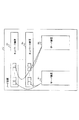
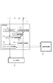
図1は、本実施形態における負荷分散制御システムの構成を示すブロック図である。本実施形態の負荷分散制御システムは、ノード装置1内にネットワーク装置21〜2nとサーバ装置31,32を有している。なお、ここでは一例としてサーバ装置が2つの構成を示しているが、3つ以上のサーバ装置が相互に接続された構成であってもよい。
FIG. 1 is a block diagram showing a configuration of a load distribution control system in the present embodiment. The load distribution control system of the present embodiment includes
ネットワーク装置21〜2nは、複数のサーバ装置31,32を相互に接続し、サーバ装置31,32間の通信を可能にする。
The
各サーバ装置31,32は、ネットワーク装置21〜2nを介して相互に接続され、冗長構成となっている。
The
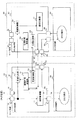
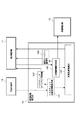
図2は、本実施形態のサーバ装置31,32の冗長構成を示すブロック図である。サーバ装置31は、タスク転送部41およびタスク処理部51を有している。サーバ装置32は、タスク転送部42およびタスク処理部52を有している。サーバ装置31において、タスク転送部41は、順序制御部11、同期制御部12、冗長制御部13、処理時間管理部14、およびインタフェース71,72,73,74,75,76を有している。サーバ装置32において、タスク転送部42は、順序制御部61、同期制御部62、冗長制御部63、処理時間管理部64、およびインタフェース81,82,83,84,85,86を有している。
FIG. 2 is a block diagram showing a redundant configuration of the
サーバ装置31は、外部装置(不図示)からコマンド・データを受信して、自身で実処理を行うか、あるいは伝送路を介して接続されているサーバ装置32にコマンド・データを転送する。
The
サーバ装置32は、サーバ装置31から転送されたコマンド・データを受信し、受信したコマンド・データの実処理を行い、処理結果の応答をサーバ装置31に返す。
The
サーバ装置31とサーバ装置32は、同一の構成を有しており、外部装置からのコマンド・データをサーバ装置32で受信することも可能である。例えば、サーバ装置31が故障したとき、サーバ装置32はサーバ装置31と同様の処理を行うことができる。
The
順序制御部11は、外部装置から受信したコマンド・データに対して処理の順序性を保証する制御を行う。順序制御部11は、外部装置から外部インタフェース71を経由して受信したコマンド・データをキューイングおよびバッファリングする。
The
そして、順序制御部11は、処理時間管理部14から他のサーバ装置32が送信先として指定されていなければ、バッファリングしたコマンド・データを、インタフェース75を経由してタスク処理部51に送る。コマンド・データをタスク処理部51に送信した後、順序制御部11は処理開始通知情報を処理時間管理部14に送る。処理開始通知情報は、タスク処理部51,52に実処理を要求したことを示す情報である。
Then, the
また、順序制御部11は、タスク処理部51からインタフェース76を経由して処理結果を受け取る。タスク処理部51から処理結果を受けると、順序制御部11は、処理終了通知情報を処理時間管理部14に送るとともに、処理結果をインタフェース72を介して外部装置に送る。処理終了通知情報は、タスク処理部51,52が実処理を終了したことを示す情報である。
Further, the
順序制御部11は、処理時間管理部14から他のサーバ装置32が送信先として指定されていれば、インタフェース74を経由してサーバ装置32のタスク転送部42にコマンド・データを転送する。そして、順序制御部11は、サーバ装置32のタスク転送部42からインタフェース73を経由してコマンド・データの処理結果を受けると、サーバ装置32の処理終了通知情報を処理時間管理部14に送るとともに、処理結果をインタフェース72を介して外部装置に返送する。
The
その際、サーバ装置31とサーバ装置32はそれぞれ独立に処理を実行するので、順序制御部11の入力で見ると、サーバ装置31の処理結果とサーバ装置32の処理結果の順序性は保証されていない。そこで、順序制御部11は、サーバ装置31の処理結果とサーバ装置32の処理結果の順序を正常にして外部装置に返送する。
At this time, since the
同期制御部12は、冗長構成のサーバ装置31とサーバ装置32の間の処理の同期をとる。同期制御部12は、インタフェース71からのコマンド・データを受信する。また、同期制御部12は、処理時間管理部14から処理開始情報と各サーバ装置31,32の処理終了通知情報を受信する。同期制御部12は、インタフェース71からのコマンド・データと処理時間管理部14からの処理開始通知情報とを他のサーバ装置32の同期制御部62に送信する。サーバ装置32の同期制御部62は、サーバ装置31の同期制御部12からコマンド・データと処理開始通知情報を受信すると、受信したコマンド・データと処理開始通知情報を同期情報として蓄積する。
The
また、同期制御部12は、処理時間管理部14からの処理終了通知情報を他のサーバ装置32の同期制御部62に送信する。サーバ装置32の同期制御部62は、処理終了通知情報を受信すると、同期情報として蓄積したコマンド・データおよび処理開始情報を同期制御部62から消去する。
In addition, the
冗長制御部13は、ヘルスチェックによって他サーバ装置32の正常性および他サーバ装置32との伝送路の正常性を監視する。冗長制御部13は、伝送路を介して他のサーバ装置32の冗長制御部63に定期的にヘルスチェックデータを送信し、そのサーバ装置32の冗長制御部63からヘルスチェックデータを受信することによって、伝送路の状態を監視する。冗長制御部13は、監視結果からヘルスチェック送受信情報を生成して処理時間管理部14に送信する。ヘルスチェック送受信情報は、ヘルスチェックデータを送信した時刻とヘルスチェックデータを受信した時刻を含む情報である。
The
また、冗長制御部13は、自装置の動作状態およびインタフェースのリンク状態を監視する。冗長制御部13は、自装置で処理を継続できない障害を検出すると、他のサーバ装置32の冗長制御部63に障害情報を通知する。障害情報は、サーバ装置31の故障を他のサーバ装置32の冗長制御部63に通知するための情報である。同期制御部62は、冗長制御部63が障害情報を受信したことを検知すると、蓄積している同期情報を順序制御部61に送信する。順序制御部61は、同期制御部62から同期情報を受信すると、サーバ装置31の順序制御部11が行っていた処理を、同期情報を用いて引き継ぎ、その後の処理を開始する。
Further, the
処理時間管理部14は、伝送路の負荷状態とコマンド・データの処理時間を管理する。処理時間管理部14は、冗長制御部13からヘルスチェック送受信情報を受信すると、そのヘルスチェック送受信情報に含まれるヘルスチェックデータの送信時刻と受信時刻からヘルスチェックの所要時間を算出する。また、処理時間管理部14は、ヘルスチェックデータが送信された後、一定時間内に応答のヘルスチェックデータが受信されていなければ、そのサーバ装置32をコマンド・データの送信先から除外するよう順序制御部11に要求する。
The processing
また、処理時間管理部14は、順序制御部11から処理開始通知情報と処理終了通知情報を受信し、それらを受信した時刻を記憶する。そして、処理時間管理部14は、処理開始通知情報を受信した時刻と、処理終了通知情報を受信した時刻とから実処理の所要時間を算出し、算出した実処理の所要時間によって、サーバ装置31,32の負荷状態を監視する。
In addition, the processing
処理時間監視部14は、コマンド・データの送信先から除外されていないサーバ装置31,32の中から、ヘルスチェックの所要時間および実処理の所要時間を用いて、送信先とするサーバ装置を決定し、順序制御部11に通知する。また、処理開始通知情報を受信した後、それに対応する処理終了通知情報を所定時間内に受信できなければ、処理時間管理部14は順序制御部11にコマンド・データの再送を要求する。
The processing
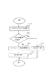
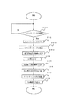
図3は、本実施形態のサーバ装置31,32におけるヘルスチェックを行う際の動作を示すフローチャートである。冗長制御部13は、伝送路を介して接続されている他のサーバ装置32の冗長制御部63にヘルスチェックデータを送信する(ステップ100)。処理時間管理部14は、そのサーバ装置32の冗長制御部63から所定の時間内にヘルスチェックデータを受信したか否かを判定する(ステップ101)。
FIG. 3 is a flowchart illustrating an operation when performing a health check in the
サーバ装置32の冗長制御部63からヘルスチェックデータを所定の時間内に受信すると、処理時間管理部14は、ヘルスチェックの所要時間を算出する(ステップ102)。処理時間管理部14は算出したヘルスチェックの所要時間に基づいて送信先となるサーバ装置を指定する(ステップ103)。サーバ装置32の冗長制御部63からヘルスチェックデータを所定の時間内に受信しないと、所要時間管理部14は、サーバ装置32を送信先から除外する(ステップ104)。
When the health check data is received from the
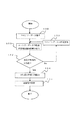
図4は、本実施形態のサーバ装置31,32における実処理を行う際の動作を示すフローチャートである。順序制御部11は、コマンド・データを受信する(ステップ150)。順序制御部11は、受信したコマンド・データを自装置のタスク処理部51または送信先となるサーバ装置32のタスク転送部42に転送し、その後、処理開始通知情報を処理時間管理部14に送信する(ステップ151)。
FIG. 4 is a flowchart showing an operation when performing actual processing in the
処理時間管理部14は、対応する処理終了通知情報を所定の時間内に受信したか否かを判定する(ステップ152)。対応する処理終了通知情報を所定の時間内に受信できなければ、処理時間管理部14は順序制御部11にコマンド・データの再送を要求する(ステップ153)。対応する処理終了通知情報を所定の時間内に受信すれば、処理時間管理部14は実処理の所要時間を算出する(ステップ154)。処理時間管理部14は、新たに算出した実処理の所要時間に基づいて送信先を指定する(ステップ155)。
The processing
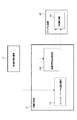
図5は、本実施形態の順序制御部11の構成を示すブロック図である。本順序制御部11は、バッファ格納処理部111、次コマンド・データ設定処理部112、コマンド・データ送信処理部113、処理結果受信処理部114、バッファ削除処理部115、および処理結果送信処理部116を有している。
FIG. 5 is a block diagram illustrating a configuration of the
バッファ格納処理部111は、外部装置から受信したコマンド・データをメモリ上(不図示)に格納し、処理順序キューに登録する。 The buffer storage processing unit 111 stores command data received from an external device on a memory (not shown) and registers it in a processing order queue.
次コマンド・データ設定処理部112は、処理結果受信処理部114から次の処理が実行可能となった旨の通知を受け取ると、バッファ格納処理111に登録されたコマンド・データを読み込んで、コマンド・データ送信処理部113に送る。
When the next command / data setting
コマンド・データ送信処理部113は、処理時間管理部14から他のサーバ装置32が送信先として指定されていなければ、コマンド・データ設定処理部112からのコマンド・データをタスク処理部51に送る。また、コマンド・データ送信処理部113は、処理時間管理部14から他のサーバ装置32が送信先として指定されていれば、コマンド・データ設定処理部112からのコマンド・データを自装置のタスク処理部51または送信先となるサーバ装置32のタスク転送部42にコマンド・データを転送する。コマンド・データを転送した後、コマンド・データ送信処理部113は処理開始通知情報を処理時間管理部14に送る。
The command / data
処理結果受信処理部114は、タスク処理部51から処理結果を受け取ると、その処理結果を処理結果送信処理部116に送るとともに、処理終了通知情報を処理時間管理部14に送る。また、それとともに、処理結果受信処理部114は、次コマンド・データ設定処理部112に次の処理が実行可能となった旨を通知し、バッファ削除処理部115に処理が完了した旨を通知する。
When the processing result
バッファ削除処理部115は、処理結果受信処理部114から処理の完了を通知されると、その処理が完了したコマンド・データをバッファから削除する。
When the completion of processing is notified from the processing result
処理結果送信処理部116は、処理結果受信処理部114から処理結果を受けると、処理結果の順序を正常にして、外部装置に処理結果を返送する。
When receiving the processing results from the processing result
図6は、本実施形態の順序制御部11の動作を示すフローチャートである。バッファ格納処理部111は、外部装置から受信したコマンド・データをメモリ上に格納するとともに、処理順序キューに登録する。
FIG. 6 is a flowchart showing the operation of the
次コマンド・データ設定処理部112は、バッファ格納処理部111の処理順序キューにコマンド・データが登録されているか否かを判定する(ステップ200)。バッファ格納処理部111に次のコマンド・データが登録されていると、次コマンド・データ設定処理部112は、バッファ格納処理部111のメモリ上からコマンド・データを読み込む(ステップ201)。
The next command / data setting
コマンド・データ送信処理部113は、処理時間管理部14から他のサーバ装置32が送信先として指定されていなければ、読み込まれたコマンド・データを自装置のタスク処理部51に送る(ステップ202)。コマンド・データをタスク処理部51に送信した後、コマンド・データ送信処理部113は処理開始通知情報を処理時間管理部14に送る(ステップ203)。タスク処理部51は、処理が完了すると、処理結果を処理結果受信処理部114に送る(ステップ204)。
The command / data
処理結果受信処理部114は、タスク処理部51から処理結果を受け取ると、処理終了通知情報を処理時間管理部14に送る(ステップ205)。
When receiving the processing result from the
また、処理結果受信処理部114は、次コマンド・データ設定処理部112に次の処理が実行可能となった旨を通知する(ステップ206)。
Further, the processing result
さらに、処理結果受信処理部114は、バッファ削除処理部115に処理が完了した旨を通知する。バッファ削除処理部115は、処理結果受信処理部114から処理が完了した旨を通知されると、その処理が完了したコマンド・データをバッファから削除する(ステップ207)。
Furthermore, the processing result
次に、処理結果受信処理部114は、処理結果送信処理部116に処理結果を送信する。処理結果送信処理部116は、処理結果受信処理部114から処理結果を受け取ると、順序を正常にして処理結果を外部装置に返送する(ステップ208)。
Next, the processing result
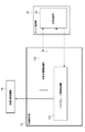
図7は、本実施形態の同期制御部12の構成を示すブロック図である。同期制御部12は、コマンド・データ転送処理部121および処理状態転送処理部122を有している。
FIG. 7 is a block diagram showing a configuration of the
コマンド・データ転送処理部121は、コマンド・データを他のサーバ装置32のタスク転送部42内にある同期制御部62に送信する。
The command / data
処理状態転送処理部122は、処理時間管理部14から処理開始通知情報と処理終了通知情報とを受信し、受信した処理開始通知情報と処理終了通知情報を同期制御部62に送信する。
The processing state
他のサーバ装置32では、タスク転送部42内の同期制御部62がコマンド・データ転送処理121と処理状態転送処理部122からコマンド・データおよび処理開始通知情報を受信して同期情報として蓄積する。また、タスク転送部42内の同期制御部62は、処理状態転送処理部122からの処理終了通知情報を受信すると、同期情報として蓄積したコマンド・データおよび処理開始通知情報を同期制御部62から消去する。
In the
図8は、本実施形態の冗長制御部13の構成を示すブロック図である。冗長制御部13は、ヘルスチェック監視処理部131および外部IF監視処理部132を有している。
FIG. 8 is a block diagram showing the configuration of the
ヘルスチェック監視処理部131は、伝送路を介して他のサーバ装置32の冗長制御部63にヘルスチェックデータを送信し、そのサーバ装置32の冗長制御部63から応答のヘルスチェックデータを受信する。ヘルスチェック監視処理部131は、ヘルスチェックデータの送受信を示すヘルスチェック送受信情報を生成して処理時間管理部14に送信する。
The health check
外部IF監視処理部132は、自装置(サーバ装置31)の動作状態およびインタフェースのリンク状態を監視する。外部IF監視処理部132は、物理レイヤレベルの状態を監視してサーバ装置31の故障を検出する。サーバ装置31の故障を検出すると、外部IF監視処理部132は障害情報を冗長制御部63に通知する。
The external IF
図9は、本実施形態の処理時間管理部14の構成を示すブロック図である。処理時間管理部14は、ヘルスチェック送受信情報受信部141、ヘルスチェックタイムアウト監視部142、送受信情報受信部143、送信タイムアウト監視部144、および処理負荷演算部145を有している。
FIG. 9 is a block diagram illustrating a configuration of the processing
ヘルスチェック送受信情報受信部141は、冗長制御部13からヘルスチェック送受信情報を受信すると、ヘルスチェックタイムアウト監視部142と処理負荷演算部145にヘルスチェック送受信情報を送信する。
When receiving the health check transmission / reception information from the
ヘルスチェックタイムアウト監視部142は、ヘルスチェック送受信情報受信部141からヘルスチェックデータの送信を示すヘルスチェック送受信情報を受信した後、所定時間内にヘルスチェックデータの受信を示すヘルスチェック送受信情報を受信できたか否かを判定する。ヘルスチェックタイムアウト監視部142は、ヘルスチェックが所定時間内に完了しなければ、そのサーバ装置32を送信先から除外するよう順序制御部11に要求する。
The health check
送受信情報受信部143は、順序制御部11から処理開始通知情報または処理終了通知情報を受信すると、送信タイムアウト監視144、処理負荷演算部145、および同期制御部12に処理開始通知情報または処理終了通知情報を送信する。
When the transmission / reception information reception unit 143 receives the processing start notification information or the processing end notification information from the
送信タイムアウト監視部144は、処理開始通知情報を受信した時刻から所定時間内に処理終了通知情報を受信したか否かを判定する。送信タイムアウト監視部144は、所定時間内に処理終了通知情報を受信できなければ、順序制御部11にコマンド・データを再送するように要求する。
The transmission
処理負荷演算部145は、ヘルスチェック送受信情報受信部141からヘルスチェック送受信情報を受信すると、そのヘルスチェック送受信情報に含まれる送信時刻と受信時刻からヘルスチェックの所要時間を算出する。
When receiving the health check transmission / reception information from the health check transmission / reception
また、処理負荷演算部145は、送受信情報受信部143から処理開始通知情報と処理終了通知情報を受信すると、それらを受信した時刻を記憶する。そして、処理負荷演算部145は、処理開始通知情報を受信した時刻と、処理終了通知情報を受信した時刻とから処理開始から処理完了までの実処理の所要時間を算出する。なお、送受信情報受信部143から処理負荷分散演算部145へは自装置の処理開始通知情報および処理終了通知情報と、他のサーバ装置32の処理開始通知情報および処理終了通知情報とが通知される。そのため、処理負荷演算部145は、自装置の実処理の所要時間と他のサーバ装置32の実処理の所要時間とを算出することとなる。
Further, when the processing
処理負荷演算部145は、算出したヘルスチェックの所要時間と実処理の所要時間とから、送信先とするサーバ装置を決定し、順序制御部11に通知する。例えば、処理負荷演算部145は、ヘルスチェックの所要時間が最も短いサーバ装置を送信先として順序制御部11に通知する。順序制御部11は、送信先とされたサーバ装置にコマンド・データを転送する。また、処理負荷演算部145は、実処理の所要時間を算出し、算出した実処理の所要時間が最も短いサーバ装置を送信先として順序制御部11に通知する。
The processing
以上説明したように、本実施形態によれば、サーバ装置31のタスク転送部41がタスク処理部51の実処理の負荷および他サーバ装置32の実処理の負荷に加えて、他サーバ装置32との間の伝送路の負荷を監視し、それら実処理の負荷と伝送路の負荷に基づいてコマンド・データの割り当て先を決定する。そのため、実処理だけでなく伝送路の負荷をも考慮してネットワークに接続された負荷を分散することができ、応答の即時性を向上させることができる。
As described above, according to the present embodiment, the
なお、本実施形態ではコマンド・データを一旦転送した後に、そのコマンド・データの転送先を変更することはないが、本発明はこれに限定されるものではない。他の例として、サーバ装置31は、サーバ装置32にコマンド・データを転送してから一定時間内にサーバ装置32から受け付けを通知する応答が無ければ、このコマンド・データをサーバ装置32以外のサーバ装置(不図示)に転送して処理を行わせることにしてもよい。
In this embodiment, the command / data transfer destination is not changed after the command / data is once transferred, but the present invention is not limited to this. As another example, if there is no response for notification of acceptance from the
1 ノード装置
2 伝送路装置
3 サーバ装置
4 タスク転送部
5 タスク処理部
11 順序制御部
12 同期制御部
13 冗長制御部
14 処理時間管理部
100〜104、150〜155、200〜209 ステップ
DESCRIPTION OF
Claims (9)
伝送路を介して相互に接続され、それぞれがコマンドの実処理を実行する複数のサーバ装置を有し、前記複数のサーバ装置の少なくとも1つが、
割り当てられたコマンドの実処理を実行する処理部と、
前記処理部の実処理の負荷および他サーバ装置の実処理の負荷と、前記他サーバ装置との間の前記伝送路の負荷を監視しており、処理要求のコマンドを受けると、前記処理部の実処理の負荷と前記他サーバ装置の実処理の負荷と前記伝送路の負荷とに基づいて前記コマンドの割り当て先を決め、該コマンドを該割り当て先に転送する転送部と、を有する負荷分散制御システム。 A load balancing control system that distributes loads and executes processes,
Each of the plurality of server devices includes a plurality of server devices that are connected to each other via a transmission line and that execute actual processing of a command.
A processing unit for executing the actual processing of the assigned command;
The actual processing load of the processing unit and the actual processing load of the other server device, and the load of the transmission path between the other server device are monitored. A load distribution control comprising: a transfer unit that determines an assignment destination of the command based on an actual processing load, an actual processing load of the other server device, and a load of the transmission path, and transfers the command to the assignment destination system.
伝送路を介して相互に接続され、それぞれがコマンドの実処理を実行する複数のサーバ装置を有し、前記複数のサーバ装置の少なくとも1つが、
割り当てられたコマンドの実処理を実行し、
前記実処理の負荷および他サーバ装置の実処理の負荷と、前記他サーバ装置との間の前記伝送路の負荷を監視し、処理要求のコマンドを受けると、前記実処理の負荷と前記他サーバ装置の実処理の負荷と前記伝送路の負荷とに基づいて前記コマンドの割り当て先を決め、該コマンドを該割り当て先に転送する負荷分散制御方法。 A load balancing control method for executing processing by distributing a load,
Each of the plurality of server devices includes a plurality of server devices that are connected to each other via a transmission line and that execute actual processing of a command.
Execute the actual processing of the assigned command,
The load of the actual process and the load of the actual process of the other server apparatus and the load of the transmission path between the other server apparatus are monitored, and upon receiving a process request command, the load of the actual process and the other server A load distribution control method for determining an assignment destination of the command based on an actual processing load of the apparatus and a load on the transmission path, and transferring the command to the assignment destination.
割り当てられたコマンドの実処理を実行する処理部と、
前記処理部の実処理の負荷および他のサーバ装置の実処理の負荷と、前記他サーバ装置との間の前記伝送路の負荷を監視しており、処理要求のコマンドを受けると、前記処理部の実処理の負荷と前記他サーバ装置の実処理の負荷と前記伝送路の負荷とに基づいて前記コマンドの割り当てを決め、該コマンドを該割り当て先に転送する転送部と、を有するサーバ装置。 A server device constituting a load balancing control system in which a plurality of server devices are connected via a transmission line,
A processing unit for executing the actual processing of the assigned command;
The processing unit monitors the actual processing load of the processing unit, the actual processing load of the other server device, and the load of the transmission path between the other server device, and receives the processing request command, the processing unit And a transfer unit that determines allocation of the command based on the actual processing load of the other server device, the actual processing load of the other server device, and the load of the transmission path, and transfers the command to the allocation destination.
Priority Applications (1)
| Application Number | Priority Date | Filing Date | Title |
|---|---|---|---|
| JP2006181428A JP2008009852A (en) | 2006-06-30 | 2006-06-30 | Load distribution control system and method, and server device |
Applications Claiming Priority (1)
| Application Number | Priority Date | Filing Date | Title |
|---|---|---|---|
| JP2006181428A JP2008009852A (en) | 2006-06-30 | 2006-06-30 | Load distribution control system and method, and server device |
Publications (1)
| Publication Number | Publication Date |
|---|---|
| JP2008009852A true JP2008009852A (en) | 2008-01-17 |
Family
ID=39067977
Family Applications (1)
| Application Number | Title | Priority Date | Filing Date |
|---|---|---|---|
| JP2006181428A Pending JP2008009852A (en) | 2006-06-30 | 2006-06-30 | Load distribution control system and method, and server device |
Country Status (1)
| Country | Link |
|---|---|
| JP (1) | JP2008009852A (en) |
Cited By (2)
| Publication number | Priority date | Publication date | Assignee | Title |
|---|---|---|---|---|
| JP2013069075A (en) * | 2011-09-21 | 2013-04-18 | Toshiba Tec Corp | Computer system and job control method |
| JP5218548B2 (en) * | 2008-03-13 | 2013-06-26 | 富士通株式会社 | Job allocation apparatus, control program and control method for job allocation apparatus |
Citations (5)
| Publication number | Priority date | Publication date | Assignee | Title |
|---|---|---|---|---|
| JPH07168790A (en) * | 1993-12-15 | 1995-07-04 | Oki Electric Ind Co Ltd | Information processor |
| JPH09160884A (en) * | 1995-12-04 | 1997-06-20 | Mitsubishi Electric Corp | Dynamic load balancing parallel computer |
| JPH1139175A (en) * | 1997-07-22 | 1999-02-12 | Mitsubishi Electric Corp | Network queuing system |
| JP2003208414A (en) * | 2002-01-11 | 2003-07-25 | Hitachi Ltd | Server and client with load balancing function |
| JP2005031736A (en) * | 2003-07-07 | 2005-02-03 | Hitachi Information Systems Ltd | Server load balancing apparatus, server load balancing method, and client server system |
-
2006
- 2006-06-30 JP JP2006181428A patent/JP2008009852A/en active Pending
Patent Citations (5)
| Publication number | Priority date | Publication date | Assignee | Title |
|---|---|---|---|---|
| JPH07168790A (en) * | 1993-12-15 | 1995-07-04 | Oki Electric Ind Co Ltd | Information processor |
| JPH09160884A (en) * | 1995-12-04 | 1997-06-20 | Mitsubishi Electric Corp | Dynamic load balancing parallel computer |
| JPH1139175A (en) * | 1997-07-22 | 1999-02-12 | Mitsubishi Electric Corp | Network queuing system |
| JP2003208414A (en) * | 2002-01-11 | 2003-07-25 | Hitachi Ltd | Server and client with load balancing function |
| JP2005031736A (en) * | 2003-07-07 | 2005-02-03 | Hitachi Information Systems Ltd | Server load balancing apparatus, server load balancing method, and client server system |
Cited By (2)
| Publication number | Priority date | Publication date | Assignee | Title |
|---|---|---|---|---|
| JP5218548B2 (en) * | 2008-03-13 | 2013-06-26 | 富士通株式会社 | Job allocation apparatus, control program and control method for job allocation apparatus |
| JP2013069075A (en) * | 2011-09-21 | 2013-04-18 | Toshiba Tec Corp | Computer system and job control method |
Similar Documents
| Publication | Publication Date | Title |
|---|---|---|
| CN109274707B (en) | Load scheduling method and device | |
| KR101781063B1 (en) | Two-level resource management method and appratus for dynamic resource management | |
| US20200104170A1 (en) | Systems and methods for scheduling tasks | |
| US9172646B2 (en) | Dynamic reconfiguration of network devices for outage prediction | |
| CN102571568B (en) | Task processing method and device | |
| JP2012103879A (en) | Session management method, session management system, and program | |
| JP5757325B2 (en) | Virtual desktop system, network processing apparatus, management method, and management program | |
| CN105933408A (en) | Implementation method and device of Redis universal middleware | |
| KR20200080458A (en) | Cloud multi-cluster apparatus | |
| WO2016135919A1 (en) | Storage device | |
| JP4612714B2 (en) | Data processing method, cluster system, and data processing program | |
| CN106603692A (en) | Data storage method in distributed storage system and apparatus thereof | |
| US8854977B2 (en) | Relay node | |
| CN103001787B (en) | System and method for data processing centre's disaster-tolerant backup | |
| JP4309321B2 (en) | Network system operation management method and storage apparatus | |
| JP2008283608A (en) | Computer, program and method for switching redundant communication paths | |
| JP5526780B2 (en) | Load distribution system, service processing server, load distribution method, and load distribution program | |
| TWM432075U (en) | Monitoring device and monitoring system applicable to cloud algorithm | |
| JP5876425B2 (en) | Virtual machine live migration scheduling method and virtual machine system | |
| CN120631662A (en) | Data transmission method, device, storage medium and computer program product | |
| JP2016177324A (en) | Information processing apparatus, information processing system, information processing method, and program | |
| JP2009237835A (en) | Web server system and load distribution method | |
| JP2000200245A (en) | Information use system and information use method | |
| JP5691248B2 (en) | Task takeover program, processing device, and computer system | |
| JP2008060971A (en) | Information processing system, information processing apparatus, information processing method, and program |
Legal Events
| Date | Code | Title | Description |
|---|---|---|---|
| A621 | Written request for application examination |
Free format text: JAPANESE INTERMEDIATE CODE: A621 Effective date: 20090519 |
|
| A977 | Report on retrieval |
Free format text: JAPANESE INTERMEDIATE CODE: A971007 Effective date: 20100921 |
|
| A131 | Notification of reasons for refusal |
Free format text: JAPANESE INTERMEDIATE CODE: A131 Effective date: 20100929 |
|
| A02 | Decision of refusal |
Free format text: JAPANESE INTERMEDIATE CODE: A02 Effective date: 20110208 |