JP2007535865A - Hybrid dot line halftone synthesis screen - Google Patents
Hybrid dot line halftone synthesis screen Download PDFInfo
- Publication number
- JP2007535865A JP2007535865A JP2007510803A JP2007510803A JP2007535865A JP 2007535865 A JP2007535865 A JP 2007535865A JP 2007510803 A JP2007510803 A JP 2007510803A JP 2007510803 A JP2007510803 A JP 2007510803A JP 2007535865 A JP2007535865 A JP 2007535865A
- Authority
- JP
- Japan
- Prior art keywords
- halftone
- image
- dot
- screen
- cell
- Prior art date
- Legal status (The legal status is an assumption and is not a legal conclusion. Google has not performed a legal analysis and makes no representation as to the accuracy of the status listed.)
- Pending
Links
Images


Classifications
-
- H—ELECTRICITY
- H04—ELECTRIC COMMUNICATION TECHNIQUE
- H04N—PICTORIAL COMMUNICATION, e.g. TELEVISION
- H04N1/00—Scanning, transmission or reproduction of documents or the like, e.g. facsimile transmission; Details thereof
- H04N1/46—Colour picture communication systems
- H04N1/52—Circuits or arrangements for halftone screening
Abstract
ハーフトーン・スクリーンを用いて多色画像を生成する方法および装置は、1種類以上の色のドット構造ドット成長パターンおよび少なくとも2種類の他のライン構造ドット成長パターンを用いる。 A method and apparatus for generating a multicolor image using a halftone screen uses one or more color dot structure dot growth patterns and at least two other line structure dot growth patterns.
Description
本発明は、ディスプレイまたは印刷システム上にカラー再現を形成するための画像情報のデジタル符号化の分野に関する。 The present invention relates to the field of digital encoding of image information to form a color reproduction on a display or printing system.
デジタル技術を使用した印刷の出現に伴ない、画像をピクセルの組で表現することにより、当該画像を印刷することができる。完全な2値プリンタでは、ピクセルはオン(黒)またはオフ(白)のいずれかである。シンボルを形成する個々のピクセルの大きさが当該シンボルよりも極めて小さいため、このような技術はテキストの再現に良く適している。従って、それらが近接したドットの集合であるにもかかわらず、人間の目にはテキストが連続した画像に見える。 With the advent of printing using digital technology, an image can be printed by representing the image with a set of pixels. In a complete binary printer, the pixels are either on (black) or off (white). Such techniques are well suited for text reproduction because the size of the individual pixels forming a symbol is much smaller than that symbol. Therefore, even though they are a collection of adjacent dots, the human eye sees a continuous image of text.
しかし、大多数の2値印刷エンジン、および特に電子写真印刷エンジンでは他の画像、例えば写真等において許容できるグレーレベルが得られない。当業者は、連続トーンを有する画像を再現すべくハーフトーン・ドットを用いて擬似的にグレースケールを表わしていた。その理由の一つは、たとえ印刷システムが極めて小さい2値ピクセルの印刷に適していても、印刷ドットの形成に用いる粒子が望ましい大きさを超える場合があるためである。 However, the majority of binary print engines, and especially electrophotographic print engines, do not provide acceptable gray levels in other images, such as photographs. Those skilled in the art have simulated grayscale using halftone dots to reproduce an image having continuous tones. One reason is that even if the printing system is suitable for printing very small binary pixels, the particles used to form the printed dots may exceed the desired size.
デジタル印刷(以下「印刷」という用語は、印刷と表示の両方を含むように用いる)において、多くの異なる方法によりグレーレベルが実現されてきた。2値ディスプレイおよびプリンタによる色の濃さ、すなわちグレーレベルの表現が各種のアルゴリズムの目的であった。2値ディスプレイおよびプリンタはマークの印字を、通常はドット形式で、所与の均一サイズおよび、単位長当たりのマーク数、通常は1インチ(2.54センチメートル)当たりのドット数、の解像度で行なうことができる。一群のマークを肉眼で見た際に背景(通常は白い用紙)色と完全な塗りつぶし、すなわち中実密度色との間の中間色調が合成されるように、各種の幾何学的なパターンに従いマークを配置する方法は広く知られていた。その効果は、肉眼で見た際に、ドットおよびドットが存在しない空白点のグループにより、中間色調、すなわち通常は白い印字前の用紙と、インクによる完全塗りつぶし、あるいは中実密度のハーフトーン・ドットの間の中間色調または密度が合成されることである。ドットを行に並べて、行間隔として知られる行間の距離が1インチ当たり行数(lpi)を決定する方式が便利である。以下の段落において、白色用紙に関して述べる。但し白色用紙は説明用であって本発明を限定するものではなく、プラスチック、織物、コーティング用紙、金属、木材、食用品等の他の媒体を用いてもよいことを理解されたい。 In digital printing (hereinafter the term “printing” is used to include both printing and display), gray levels have been achieved in many different ways. Representation of color strength, i.e., gray level, by binary displays and printers was the purpose of various algorithms. Binary displays and printers print marks at a resolution of a given uniform size and number of marks per unit length, usually dots per inch (typically 2.54 centimeters), usually in dot format. Can be done. Marks according to various geometric patterns so that when a group of marks is viewed with the naked eye, a halftone between the background (usually white paper) color and a full fill, ie a solid density color, is synthesized. The method of arranging was widely known. The effect is that when viewed with the naked eye, dots and groups of blank points where no dots are present make it possible to achieve neutral tones, i.e. normally white preprinted paper and full ink or solid density halftone dots. An intermediate tone or density in between is to be synthesized. It is convenient to arrange dots in rows and determine the number of rows per inch (lpi) as the distance between rows known as row spacing. In the following paragraphs, white paper will be described. However, it should be understood that white paper is illustrative and does not limit the present invention, and other media such as plastic, fabric, coated paper, metal, wood, edible food, etc. may be used.
連続階調画像は、見かけ上連続したグレーレベルを含んでいる。いくつかのシーンでは、人間が見た際に、ある陰影から別の陰影へ移る連続したグレーレベルの見かけを与えるために各々の色について256以上の離散的なグレーレベルが必要となる場合がある。ハーフトーンのピクトリアルまたはグラフィカル画像は、用紙と階調画像との間の高いコントラストを下げることにより、視覚的により快適な画像を生成する。連続階調画像の近似として、2値ハーフトーン技術を用いてピクトリアル画像を表現していた。ハーフトーン画像を記録または表示すべく、記録または表示面の1個の画素はj×kマトリクスまたは部分画素のセルで構成され、ここにjおよびkは正整数である。ハーフトーン画像は、各々の部分画素(ピクセルまたはペル)を印刷するか、または空白のまま残すことにより、すなわち、印刷されたマークを各セル内に最適に分散することにより再現される。 A continuous tone image includes apparently continuous gray levels. Some scenes may require more than 256 discrete gray levels for each color to give the appearance of a continuous gray level from one shadow to another when viewed by humans. . Halftone pictorial or graphical images produce a visually more comfortable image by reducing the high contrast between the paper and the tonal image. As an approximation of a continuous tone image, a pictorial image is expressed using a binary halftone technique. In order to record or display a halftone image, one pixel on the recording or display surface is composed of a j × k matrix or a cell of partial pixels, where j and k are positive integers. A halftone image is reproduced by printing each partial pixel (pixel or pel) or leaving it blank, i.e. optimally distributing the printed marks within each cell.
グレーレベルを生成する別の方法が、グレーレベル印刷により提供される。そのような方法では、各ピクセルはいくつかの異なるドットサイズを合成することが可能である。例えば、ある種の電子写真印刷システムにおいて、ピクセルのドットサイズは、当該ピクセルに対応するLED素子に提供される露光時間の関数である。露光時間が長いほど、より多くのトナーが当該特定ピクセルに引き寄せられる。 Another way of generating gray levels is provided by gray level printing. In such a way, each pixel can synthesize several different dot sizes. For example, in certain electrophotographic printing systems, the dot size of a pixel is a function of the exposure time provided to the LED element corresponding to that pixel. The longer the exposure time, the more toner is drawn to the specific pixel.
印刷用の連続階調画像を合成する際に二つの主要な関心事がある。すなわち(1)画像の詳細部分の解像度、および(2)グレースケールの再現である。2値表現方式においてこれら二つの基本要素は互いに競合する。合成するグレーレベルが多いほど、ハーフトーン・セルがより大きくなる。その結果、得られるハーフトーン・ライン・スクリーンは粗く、これに伴ない画像の見栄えが悪くなる。従って、グレースケールにおけるライン解像度の選択と2値ハーフトーン印刷との間で妥協がなされてきた。しかし、グレーレベル・ハーフトーン印刷の場合、一方が解像度とグレーレベル要件の両方を満たすことができる。グレーレベル印刷において、同数のアドレス指定可能なドットが存在し、1ビット/ピクセルの1種類ドットサイズから、例えば8ビット/ピクセルの255種類の異なるドットサイズまで、ドットサイズの選択が可能である。ライン解像度および階調スケールに関してより高い画質を提供するにもかかわらず、グレーレベル・ハーフトーンは自身のドット合成に問題がある。 There are two major concerns when compositing continuous tone images for printing. That is, (1) the resolution of the detailed portion of the image, and (2) the reproduction of gray scale. In the binary representation scheme, these two basic elements compete with each other. The more gray levels that are combined, the larger the halftone cell. As a result, the resulting halftone line screen is rough, which results in a poor looking image. Thus, a compromise has been made between the choice of line resolution in grayscale and binary halftone printing. However, for gray level halftone printing, one can meet both resolution and gray level requirements. In gray level printing, there are the same number of addressable dots, and dot sizes can be selected from a single dot size of 1 bit / pixel to 255 different dot sizes of 8 bits / pixel, for example. Despite providing higher image quality with respect to line resolution and tone scale, gray level halftones have problems with their dot composition.
セルテンプレートからグレーレベル・ドットを構築するために多くの異なるドット・レイアウトが可能である。これらのグレーレベル・ドットは、グレーレベル・スクリーニングのデジタル表現であって、印刷プロセスを介して実現されなければならない。グレーレベル・スクリーニングにおいて、ドットの見栄えが肉眼に快適であるように、すなわち、粒度が細かく、安定していて、アーチファクトが少なく、テクスチャ(すなわち可視的なスクリーンおよびその微細構造)が少なくなるように、内部に印刷プロセスの特徴が取り込まれたドットを配置することが望ましい。 Many different dot layouts are possible to build gray level dots from a cell template. These gray level dots are digital representations of gray level screening and must be realized through a printing process. In gray level screening, so that the appearance of the dots is comfortable to the naked eye, that is, the granularity is fine and stable, there are few artifacts, and the texture (ie the visible screen and its microstructure) is small It is desirable to arrange dots that incorporate the features of the printing process inside.
グレースケール合成用に設計されたライン・スクリーンの例が、米国特許第5,258,850号に開示されている。ハーフトーン・セル内でのピクセルの配置は、ピクセルを成長ラインに沿って配置することにより密度の増加を表現するセル内の成長が実現されるようになされている。ハーフトーン・セルの別の例が米国特許第5,258,849号に示されており、これはセル内で中心領域の周囲に段階的に拡大していくことによりハーフトーン・セル内で密度を成長させることを特徴とするものである。上記2件の特許に開示されたハーフトーン・セルは、各セル内で必要とするピクセルの密度が異なっていてよい点が特徴的である。これにより、ピクセルを2値表現(白または黒のいずれかでサイズに関する区別は無い)でしか合成できないセルよりも、ハーフトーン・セル全体により表現することができるグレーレベルの個数が大幅に増える。セルの組合せがハーフトーン・スクリーンを表現する。 An example of a line screen designed for gray scale composition is disclosed in US Pat. No. 5,258,850. The placement of the pixels within the halftone cell is such that growth within the cell that represents an increase in density is achieved by placing the pixels along the growth line. Another example of a halftone cell is shown in U.S. Pat. No. 5,258,849, which increases density within a halftone cell by gradually expanding around the central region within the cell. It is characterized by growing. The halftone cells disclosed in the above two patents are characterized in that the required density of pixels in each cell may be different. This greatly increases the number of gray levels that can be represented by the entire halftone cell, compared to cells where the pixel can only be synthesized in binary representation (either white or black, with no distinction in size). The combination of cells represents a halftone screen.
ハーフトーン・プリンタでのカラー印刷は、各々の色に対するハーフトーン・スクリーンとして色分解の形成を伴ない、これを用いてカラー画像を形成する。ハーフトーン・スクリーンは、所定の互いに重なり合う関係に配置され、その結果所望のカラー画像が生成される。2個以上のハーフトーン・スクリーンを重ね合わせる際に良く知られた問題として、スクリーンが適切に配置されていない場合にモアレパターンその他の干渉が生じる可能性がある。モアレその他の望ましくないパターンを避けるべく、スクリーンを正確な角度で組合せることが必要である。2個の重ね合わされたドットスクリーンの角度の差異が増せば結果的にパターンが小さくなってパターンが不鮮明になることが知られている。しかし、従来技術の教示すところ、例えば米国特許第6,307,645号では、2個の重ね合わされたスクリーンに許される最大の角度差異は45°以下でなければならないとしている。その理由は、非対称のドットによりモアレの減少を試みる場合であっても、正に135°のスクリーンが45°スクリーンと同じであるように、90°のスクリーンは本質的に0°と同じであるからである。 Color printing on a halftone printer involves the formation of color separations as a halftone screen for each color, which is used to form a color image. The halftone screens are placed in a predetermined overlapping relationship, resulting in the desired color image. A well-known problem when overlaying two or more halftone screens is that moiré patterns and other interference can occur when the screens are not properly positioned. It is necessary to combine the screens at the correct angles to avoid moiré and other undesirable patterns. It is known that if the difference in angle between two superimposed dot screens increases, the pattern will eventually become smaller and the pattern will become unclear. However, according to the teachings of the prior art, US Pat. No. 6,307,645, for example, states that the maximum angular difference allowed for two superimposed screens must be 45 ° or less. The reason is that a 90 ° screen is essentially the same as 0 °, just as a 135 ° screen is the same as a 45 ° screen, even when attempting to reduce moiré with asymmetric dots. Because.
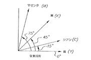
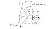
カラー画像印刷において、少なくとも3種類のプロセス色を用いるのが一般的であり、より多くの場合3種類のプロセス色と黒色を用いていた。4色印刷の場合、印刷業界では4個のハーフトーン角の標準化された組合せを開発した。特に、また図1を参照するに、シアン・ハーフトーン・スクリーンが15°、黒色ハーフトーン・スクリーンが45°、マゼンタ・ハーフトーン・スクリーンが75°、および黄色ハーフトーン・スクリーンが0°で配置されている。黄色が最も明るく且つ最も目立たない色であるため、たとえ0°が極めて目立つ角度であって最も近い隣から15°しか離れていないにもかかわらず、0°で設定することができる。いくつかの実施形態ではシアン・ハーフトーン・スクリーンを105°で配置することが知られているが、対称なドットの場合これは実質的に15°に等しく、従来技術では非対称ドットでさえ大きな違いをもたらさないことが認識されている。 In color image printing, at least three kinds of process colors are generally used, and in many cases, three kinds of process colors and black are used. For four-color printing, the printing industry has developed a standardized combination of four halftone angles. In particular, and referring also to FIG. 1, the cyan halftone screen is 15 °, the black halftone screen is 45 °, the magenta halftone screen is 75 °, and the yellow halftone screen is 0 °. Has been. Since yellow is the brightest and least noticeable color, it can be set at 0 ° even though 0 ° is a very noticeable angle and is only 15 ° away from the nearest neighbor. Although it is known in some embodiments to place the cyan halftone screen at 105 °, this is substantially equal to 15 ° for symmetric dots, and even the asymmetric dot is a significant difference in the prior art. It is recognized that it will not bring about.
上述のハーフトーン・スクリーン角の組合せを用いた4種のプロセス色が重ね合わされた場合、結果的に生じるモアレその他の干渉パターンは可能な限り小さい。個々のドット粒子の向きが30°離されている場合に、視覚的に快適なロゼット構造が形成される。従来のグラフィックス技術による印刷は、この15°/45°/75°の角度スクリーン設計を用いてバランスの取れたロゼット構造を形成することにより行なわれてきた。CMYK4色の印刷プロセスにおいて、黄色スクリーンは通常、0°または45°で設計される。しかし、見当ずれによる黄色スクリーンと他の3個の個々のスクリーンとの間の相互作用から生じるモアレパターンは、30°のモアレパターン(ロゼット構造)ほどには視覚的に快適ではない。黄色は明るい色であるため、この追加的なモアレは通常許容できて、大多数のCMYK4色印刷システムにおいてさほど目立たない。しかし、印刷結果を注意深く調べると、この黄色モアレパターンが特定の合成色に見られることがわかる。高忠実色(例えば5色)印刷システムにおけるように、追加的な色を用いる場合、元のバランスの取れたCMYKスクリーン組の上に第5のスクリーンを設計する必要がある。これは、第5のカラースクリーンが青色、すなわち黄色の補色である場合に特にそうであり、青色カラースクリーンは黄色カラースクリーンと同じスクリーン角およびスクリーン線数で配置される。黄色では目立たなかった不快なモアレが、この場合青色に現れる。 When the four process colors using the halftone screen angle combination described above are superimposed, the resulting moire and other interference patterns are as small as possible. A visually comfortable rosette structure is formed when the orientation of the individual dot particles is 30 ° apart. Printing by conventional graphics technology has been performed by using this 15 ° / 45 ° / 75 ° angle screen design to form a balanced rosette structure. In the CMYK four color printing process, the yellow screen is usually designed at 0 ° or 45 °. However, the moiré pattern resulting from the interaction between the yellow screen due to misregistration and the other three individual screens is not as visually comfortable as the 30 ° moiré pattern (rosette structure). Since yellow is a light color, this additional moiré is usually acceptable and is less noticeable in the majority of CMYK four-color printing systems. However, careful examination of the print results reveals that this yellow moiré pattern can be found in certain composite colors. When using additional colors, as in a high fidelity color (e.g., 5 color) printing system, it is necessary to design a fifth screen over the original balanced CMYK screen set. This is especially true when the fifth color screen is blue, i.e., a complementary color of yellow, where the blue color screen is arranged with the same screen angle and number of screen lines as the yellow color screen. An unpleasant moire that was not noticeable in yellow appears in blue in this case.
このように、多くのカラー印刷システムが、異なる色の顔料を用いる5個以上の印刷装置を含んでいることが知られている。これらの追加的な色を組み込む試みは、特に各々の色が一意なハーフトーン角のハーフトーン・スクリーンを備える必要がある場合に、困難であることがわかっている。特に、スクリーン角を伴なうスクリーンが4個より多くあって、これらを配置しなければならない場合、上述のパターニング問題は極めて深刻になる。従って、黄色スクリーンの相互作用により生じるものを含む、不快なモアレパターンの形成を最小限に抑える印刷用カラースクリーン・セットを提供することが望まれる。 Thus, it is known that many color printing systems include five or more printing devices that use different color pigments. Attempts to incorporate these additional colors have proven difficult, especially when each color needs to have a halftone screen with a unique halftone angle. In particular, if there are more than four screens with screen angles and these have to be placed, the above patterning problem becomes very serious. Accordingly, it would be desirable to provide a printing color screen set that minimizes the formation of unpleasant moire patterns, including those caused by yellow screen interaction.
上述の目的は、画像アーチファクトが減少し、且つグレーレベルの数が増したハーフトーン画像を生成する装置および方法を提供する本発明により達成される。本発明の第1の態様に従い、少なくとも3種類の異なる色を有する画像を印刷するための画像情報を設定する装置を提供する。当該装置は、第1の所定のハーフトーン・スクリーン角で第1のハーフトーン・セルを生成することにより、画像の第1の色分解画像を表現する情報を生成する第1のハーフトーン・スクリーン・ジェネレータにおいて、第1のハーフトーン・セル内のピクセルがライン構造に配向されていて、第1のハーフトーン・セルのセル密度が逐次増大して、より濃いライン構造として識別される、第1のハーフトーン・スクリーン・ジェネレータと、第1のハーフトーン・スクリーン角とは異なる第2の所定のハーフトーン・スクリーン角で第2のハーフトーン・セルを生成することにより、画像の第2の色分解画像を表現する情報を生成する第2のハーフトーン・スクリーン・ジェネレータにおいて、第2のハーフトーン・セル内のピクセルがライン構造で表現されていて、第2のハーフトーン・セルのセル密度が逐次増大して、より濃いライン構造として識別され、第2のハーフトーン・セル内に形成されたライン構造が第1のハーフトーン・セル内に形成されたライン構造とは異なる角度である、第2のハーフトーン・スクリーン・ジェネレータと、第3の所定のハーフトーン・スクリーン角で第3のハーフトーン・セルを生成することにより、画像の第3の色分解画像を表現する情報を生成する第3のハーフトーン・スクリーン・ジェネレータにおいて、第3のハーフトーン・セル内のピクセルがドットで表現されていて、第3のハーフトーン・セルのセル密度が逐次増大して、より濃いライン構造として識別され、第3のハーフトーン・セル画像のドット構造が、一連の平行な第3のラインに沿って並んでいて、当該一連の平行な第3のラインが、第1および第2のハーフトーン・セル内に形成されたライン構造とは異なる角度にある、第3のハーフトーン・スクリーン・ジェネレータとを含んでいる。 The above objective is accomplished by the present invention which provides an apparatus and method for generating a halftone image with reduced image artifacts and increased number of gray levels. According to a first aspect of the present invention, there is provided an apparatus for setting image information for printing an image having at least three different colors. The apparatus generates a first halftone cell at a first predetermined halftone screen angle to generate information representing a first color separation image of the image. In the generator, the pixels in the first halftone cell are oriented in a line structure and the cell density of the first halftone cell is sequentially increased to be identified as a darker line structure. Generating a second halftone cell at a second predetermined halftone screen angle different from the first halftone screen angle and a second color of the image In a second halftone screen generator that generates information representing the decomposed image, the pixels in the second halftone cell are labeled. The cell structure of the second halftone cell is sequentially increased to be identified as a darker line structure, and the line structure formed in the second halftone cell is the first structure. Generating a second halftone screen generator at a different angle from the line structure formed in the halftone cell and a third halftone cell at a third predetermined halftone screen angle Thus, in the third halftone screen generator for generating information representing the third color separation image of the image, the pixels in the third halftone cell are represented by dots, The cell density of the halftone cells is sequentially increased and identified as a darker line structure, and the dot structure of the third halftone cell image becomes a series of parallel A third halftone, lined up along three lines, wherein the series of parallel third lines is at a different angle than the line structure formed in the first and second halftone cells -Includes a screen generator.
本発明の第2の態様に従い、少なくとも3種類の異なる色を有する画像を印刷するための画像情報を設定する方法を提供する。当該方法は、第1の所定のハーフトーン・スクリーン角で第1のハーフトーン・セルを生成することにより、画像の第1の色分解画像を表現する情報を生成するステップであって、第1のハーフトーン・セル内のピクセルをライン構造に配向し、第1のハーフトーン・セルのセル密度が逐次増大して、より濃いライン構造として識別されるようにするステップと、第1のハーフトーン・スクリーン角とは異なる第2の所定のハーフトーン・スクリーン角で第2のハーフトーン・セルを生成することにより、画像の第2の色分解画像を表現する情報を生成するステップであって、第2のハーフトーン・セル内のピクセルをライン構造で表現し、第2のハーフトーン・セルのセル密度が逐次増大して、より濃いライン構造として識別されるようにして、第2のハーフトーン・セル内に形成されたライン構造が第1のハーフトーン・セル内に形成されたライン構造とは異なる角度にあるようにするステップと、第3の所定のハーフトーン・スクリーン角で第3のハーフトーン・セルを生成することにより、画像の第3の色分解画像を表現する情報を生成するステップであって、第3のハーフトーン・セル内のピクセルをドットで表現し、第3のハーフトーン・セルのセル密度が逐次増大して、より濃いライン構造として識別されるようにして、第3のハーフトーン・セル画像のドット構造が、一連の平行な第3のラインに沿って配列されていて、当該一連の平行な第3のラインが、第1および第2のハーフトーン・セル内に形成されたライン構造とは異なる角度にあるようにするステップとを含んでいる。 According to a second aspect of the present invention, there is provided a method for setting image information for printing an image having at least three different colors. The method includes generating information representing a first color separation image of an image by generating a first halftone cell at a first predetermined halftone screen angle, the method comprising: Orienting pixels in a halftone cell to a line structure so that the cell density of the first halftone cell is sequentially increased to be identified as a darker line structure; Generating information representing a second color separation image of the image by generating a second halftone cell with a second predetermined halftone screen angle different from the screen angle, The pixels in the second halftone cell are represented by a line structure, and the cell density of the second halftone cell is sequentially increased to be identified as a darker line structure. The line structure formed in the second halftone cell is at a different angle than the line structure formed in the first halftone cell; and a third predetermined halftone Generating information representing a third color separation image of the image by generating a third halftone cell at a screen angle, wherein the pixels in the third halftone cell are represented by dots And the dot structure of the third halftone cell image is a series of parallel thirds so that the cell density of the third halftone cell is sequentially increased and identified as a darker line structure. The series of parallel third lines is at a different angle than the line structure formed in the first and second halftone cells. It contains.
本発明の第3の態様に従い、少なくとも3種類の異なる色を有する画像を印刷するための画像情報を設定する装置を提供する。当該装置は、少なくとも3種類の異なる色の各々に対してハーフトーン・スクリーン色分解画像データを生成するスクリーン・ジェネレータまたはジェネレータ群を含んでいて、当該スクリーン・ジェネレータまたはジェネレータ群は所定の各スクリーン角において当該画像を表現するハーフトーン・スクリーンの形式で画像データを生成し、当該3色のうち少なくとも2色の各々に対して第1の種類のドット成長パターンが提供されて異なる密度のハーフトーン・セルを生成すべく動作し、当該3色の第3の色に対して第1の種類のドット成長パターンとは異なる第2の種類のドット成長パターンが提供されて当該3色のうち前記少なくとも2色に対して共通に用いられ、第1の種類の成長パターンはドット構造ドット成長パターンおよびライン構造ドット成長パターンからなるグループから選択され、第2の種類の成長パターンはドット構造ドット成長パターンおよびライン構造ドット成長パターンからなるグループから選択され、更に当該3色の当該少なくとも2色に対するスクリーン角と、当該3色の第3の色に対するスクリーン角の各々が互いに全て異なる。 According to a third aspect of the present invention, there is provided an apparatus for setting image information for printing an image having at least three different colors. The apparatus includes a screen generator or generator group that generates halftone screen color separation image data for each of at least three different colors, the screen generator or generator group having a predetermined screen angle. Image data is generated in the form of a halftone screen representing the image, and a first type of dot growth pattern is provided for each of at least two of the three colors to provide halftones of different densities. A second type of dot growth pattern that operates to generate a cell and that is different from the first type of dot growth pattern for the third color of the three colors is provided and said at least two of the three colors. Commonly used for colors, the first type of growth pattern is a dot structure dot growth pattern and The second type of growth pattern is selected from the group consisting of the dot structure dot growth pattern and the line structure dot growth pattern, and the screen angle of the three colors with respect to the at least two colors And the screen angles for the three third colors are all different from each other.
本発明の第4の態様に従い、少なくとも3種類の異なる色を有する画像を印刷するための画像情報を設定する方法を提供する。当該方法は、少なくとも3種類の異なる色の各々に対してハーフトーン・スクリーン色分解画像データを、所定の各スクリーン角において当該画像を表現するハーフトーン・スクリーンの形式で生成するステップを含んでいて、当該3色のうち少なくとも2色の各々に対して第1の種類のドット成長パターンが提供されて異なる密度のハーフトーン・セルを生成すべく動作し、当該3色の第3の色に対して第1の種類のドット成長パターンとは異なる第2の種類のドット成長パターンが提供されて当該3色のうち前記少なくとも2色に対して共通に用いられ、第1の種類の成長パターンはドット構造ドット成長パターンおよびライン構造ドット成長パターンからなるグループから選択され、第2の種類の成長パターンはドット構造ドット成長パターンおよびライン構造ドット成長パターンからなるグループから選択され、更に当該3色の当該少なくとも2色に対するスクリーン角と、当該3色の第3の色に対するスクリーン角の各々が互いに全て異なる。 According to a fourth aspect of the present invention, there is provided a method for setting image information for printing an image having at least three different colors. The method includes generating halftone screen color separation image data for each of at least three different colors in the form of a halftone screen representing the image at each predetermined screen angle. , A first type of dot growth pattern is provided for each of at least two of the three colors to operate to generate different density halftone cells, and for the third of the three colors A second type of dot growth pattern different from the first type of dot growth pattern is provided and used in common for the at least two of the three colors. The first type of growth pattern is a dot The second type of growth pattern is selected from the group consisting of a structural dot growth pattern and a line structure dot growth pattern, and the dot structure dot growth It is selected from the turn and the group consisting of the line structure dot growth pattern, further a screen angle with respect to the three colors of the at least two colors, each of the screen angle for the third color of the three colors are all different from each other.
本発明の第5の態様に従い、ハーフトーン・スクリーンを用いて多色画像を生成する方法を提供する。当該方法は、1種類以上の色のハーフトーン・セル用のドット構造ドット成長パターンを用いてハーフトーン・ドットを形成するステップと、他の色のうち少なくとも2色のハーフトーン・セル用のライン構造ドット成長パターンを用いてハーフトーン・ラインを形成するステップとを含んでいる。 In accordance with a fifth aspect of the present invention, a method for generating a multicolor image using a halftone screen is provided. The method includes the steps of forming a halftone dot using a dot structure dot growth pattern for one or more colors of halftone cells, and a line for at least two other halftone cells of the other colors Forming halftone lines using the structural dot growth pattern.
本発明の他の目的、利点、および新規な特徴は、本発明に関する以下の詳細説明を添付の図面と合わせて精査することにより明らかになる。 Other objects, advantages and novel features of the invention will become apparent from the following detailed description of the invention when considered in conjunction with the accompanying drawings.
図2は、フルカラー画像の印刷および本発明による改良を組み込むのに適した電子写真エンジンの基本部分を示す立面図である。本発明の一実施形態は、単一のカラー画像生成機構の組が反復的にいわゆるタンデム型に配置された電子写真エンジンを用いる印刷処理を含んでいるが、インクジェット、リソグラフィー等を含む他の種類のカラー印刷システムだけでなく、他の静電記録式カラー再現装置も本発明を利用することができる。 FIG. 2 is an elevational view showing the basic parts of an electrophotographic engine suitable for incorporating full color image printing and improvements according to the present invention. One embodiment of the present invention includes a printing process using an electrophotographic engine in which a set of single color image generation mechanisms are repeatedly arranged in a so-called tandem configuration, but other types including ink jet, lithography, etc. In addition to the color printing system of the present invention, other electrostatic recording type color reproduction apparatuses can utilize the present invention.
ここで図2を参照するに、タンデム式に配置された多数の静電記録式画像形成モジュールを備えたプリンタ装置500を示す。5個のモジュールが示しているが、本発明が少なくとも更に3色印刷可能なプリンタ装置に適用できることを理解されたい。プリンタの各モジュールは、単一の色階調画像を生成する複数の電子写真画像形成サブシステムを含んでいる。各画像形成サブシステムには、感光画像形成部材を帯電させる帯電サブシステムと、感光画像形成部材を画像毎に露光させて各々の色で色分解潜像を形成する露光システムと、画像毎に露光された感光画像形成部材を各々の色のトナーで色調を与える現像サブシステムと、各々の色分解画像を、感光画像形成部材から中間転写部材へ、更に中間転写部材から、各々の現像された色分解画像を重ね合せて受像して合成多色画像を形成する受像部材へ転写する中間転写サブシステムとが含まれている。各々のサブシステムからの各々の色分解画像が転写されたのに続いて、受像部材が融着サブシステムへ転写されて多色トナー画像を受像部材に融着させる。プリンタ500に関する更なる詳細はまた、米国特許第6,608,641号に記述されており、その内容を本明細書に引用している。
Referring now to FIG. 2, a
プリンタ装置500の5個の例証的な色モジュールは、黒色、シアン、マゼンタ、黄色および青色カラー・トナー分離画像を好適に形成するものである。第5の色として青色が好適であるように示されているが、第5の色として赤色、緑色、オレンジ、バイオレットその他の主調色(ドミナントカラー)であってよく、また5種より多くの色を印刷すべくモジュールの個数を増加させてもよいことを理解されたい。モジュール同士が類似している図2の構成要素は類似の参照番号を有し、下付き添え字B、C、M、Y、およびBEは各々が関連付けられた色モジュール、すなわち黒色(B)、シアン(C)、マゼンタ(M)、黄色(Y)および青色(BE)を示す。各モジュール(591B、591C、591M、591のY、および591BE)は、図に示すように無限ベルト形式の受像体移送ウェブ(RTW)516が全てのモジュールと共に動作し、受像部材はRTW516によりモジュールからモジュールへ移送される点を除いて構造が類似している。受像部材は給紙装置から供給され、その後で、第1のモジュールを入力する前に矢印Aで示す方向へ用紙調整ユニット(図示せず)を好適に通過する。受像部材は、よく知られている通り静電式またはグリッパー等の機械式装置によりモジュールを通過する間にRTW516に接着される。好適には、受像部材は、例えばタックダウン・コロナ帯電装置526を用いて、帯電装置から静電荷を帯電させることにより静電的にRTW516に接着される。5個の受像部材またはシート512a、512b、512c、512dおよび512eが、モジュール591BE、591B、591C、591Mおよび591Yから(同時に)画像を受像する様子を示す。上で述べたように、各々の受像部材は各モジュールから1色の画像を受像し、本例で最大5色の画像を各受像部材が受像できることを理解されたい。RTW516に伴なう受像部材の移動において、各モジュールの転写ニップ510B、510C、510M、510Yおよび510BEにおいて各々のカラー画像が受像部材へ転写される際に、受像部材の上に形成された5色画像が、受像部材の被転写面上に見当を合わせて色が重なり合うように、前段の色転写と見当を合わせた転写を行なう。受像部材は次いで、RTW516から連続的に剥がされて、矢印Bで示す方向へ送られて融着機構(図示せず)に入り、乾燥トナー像を受像部材に融着すなわち固定する。RTWは、両面を、例えば、RTWの両面の電荷を中和させるコロナ帯電装置522、523を用いて帯電させることにより再利用のために再調整される。
The five exemplary color modules of the
各カラー・モジュールは主画像形成部材、例えば、各々503B、503C、503M、503Y、および503BEとラベル付けられたドラムまたは主画像形成ローラー(PIFR)を含んでいる。各PIFR503B、503C、503M、503Y、および503BEは、各々感光面構造507B、507C、507M、507Y、および507BEを有し、各構造が有する1個以上の層の上に着色されたマーキング粒子画像またはそのような画像の異なるものが連続的に形成される(PIFRの個々の層は図示せず)。階調画像を形成すべく、PIFRの外側の面をコロナ帯電装置505B、505C、505M、505Y、および505BE等の主帯電装置、あるいははローラー・帯電装置、ブラシ・帯電装置等の他の適切な帯電装置により一様に帯電させる。一様に帯電された表面は、好適に各々の電子画像ライターにより露光される。露光装置は好適にはLEDまたは他の電気光学露光装置、例えばPIFRの表面上の帯電を選択的に変化させるレーザーである。露光装置は、再現または生成される画像に対応する静電画像を生成する。現像機構は好適にはよく知られた放電領域現像技術を用いて、各々現像機構581B、581C、581M、581Y、および581BEにより潜像受像感光ドラムへ着色されたマーキング粒子を塗布することにより現像される、これらの現像機構は好適にはいわゆる「SPD(微小粒子現像)現像剤を使用する。各々の現像機構581B、581C、581M、581Y、および581BEには、各潜像を現像すべく各々適切な電圧により電気的にバイアスが掛けられていて、その電圧は電源、例えば電源552により、または個々の電源(図示せず)により供給することができる。各々の現像剤は、トナー・マーキング粒子および磁気担体粒子を含んでいる。各々の現像機構には、色調を与える特定の色の着色トナー・マーキング粒子が関連付けられている。このように、各モジュールは、各々の感光ドラムに一連の異なるカラーマーキング粒子画像を生成する。好適である感光ドラムに代えて、感光ベルトを用いてもよい。あるいは、画像情報に応答して絶縁面上に帯電した各ピクセルを直接形成する静電帯電装置により画像を生成してもよい。
Each color module includes a main imaging member, eg, a drum or main imaging roller (PIFR) labeled 503B, 503C, 503M, 503Y, and 503BE, respectively. Each
各PIFR上に形成された各々のマーキング粒子画像は、各々の第2または中間の画像転写部材、例えば508B、508C、508M、508Y、および508BEとラベル付けられた中間転写ローラー(ITR)の各々の柔軟な面へ転写される。転写の後、適切な洗浄装置504B5、504C、504M、504Y、および504BEの各々により残留トナー画像を感光ドラムの表面から除去して、後続のトナー像の形成に再利用すべく表面を準備する。 Each marking particle image formed on each PIFR is a respective second or intermediate image transfer member, eg, each of the intermediate transfer rollers (ITR) labeled 508B, 508C, 508M, 508Y, and 508BE. Transferred to a flexible surface. After transfer, the residual toner image is removed from the surface of the photosensitive drum by each of the appropriate cleaning devices 504B5, 504C, 504M, 504Y, and 504BE to prepare the surface for reuse in subsequent toner image formation.
論理および制御装置(LCU)は、各種の部材の動作とそのタイミングを制御する各種の制御信号を、各々のトナー像の各種の転写を行なうための適当な電気バイアスと共に提供する。タイミング信号もまたモーター(M)へ供給されて、RTW516を駆動するドライブローラ513を駆動する。次いでRTWを用いて他の構成要素を駆動しても、および/または他のドライバ用いて各々のモジュール内のローラーの動作を制御してよい。プリンタ装置500に書かれる画像データを、色分解スクリーン・ジェネレータまたはジェネレータ群を含むラスター画像プロセッサ(RIP)501により処理してもよい。単一の装置を連続的に動作させて、各々の異なるスクリーンに対して異なる動作を行なうようにプログラムまたは調整することができるため、本明細書で「ジェネレータ」または「ジェネレータ群」という用語は同義に用いられる。RIPの出力は、LEDライター506BE、506B、506C、506M、および506Yの各々へ色分解印刷データを送信すべくフレームまたはラインバッファ502に保存することができる。RIPおよび/または色分解スクリーン・ジェネレータはプリンタ装置の一部であっても、あるいはそれとは遠隔にある装置であってもよい。RIPにより処理される画像データは、カラー文書スキャナまたはデジタル・カメラから取得されても、あるいはコンピュータにより生成されても、またはメモリやネットワークから取得されてもよい。RIPは所望のカラープリントを取得すべく、色補正等を含む画像処理を実行することができる。カラー画像データはRIPにより各々の色に分解されて、所望のスクリーン角およびスクリーン規則を含む閾値マトリクスを用いて各色でのハーフトーン・ドット画像データに変換される。RIPは、適切にプログラムされたコンピュータおよび/または論理装置であってよく、保存または生成された閾値マトリクスおよびテンプレートを用いて、分解カラー画像データを処理して印刷に適したハーフトーン情報の形式で合成画像データに変換すべく適合されている。
The logic and control unit (LCU) provides various control signals that control the operation and timing of various members, along with appropriate electrical biases for performing various transfers of each toner image. The timing signal is also supplied to the motor (M) to drive the
ここで図3を参照し、写真的な画像(テキスト画像とは対照的に)に対する印刷ジョブ要求があったと仮定するに、プリンタ装置500の各モジュールは、各々の分解色でハーフトーン網掛け画像を生成すべく指示される。ここに、ハーフトーン・スクリーンのセルは図3に示す角度をなしている。スクリーンの各々の角度も示すことに加えて、図3はまた、各色について、当該色に関連付けられた各々の種類のドットパターン構造を識別する。例えば、黄色ハーフトーン・スクリーンは0°であることを示し、且つドット構造ドット成長パターンが、黄色の色分解ハーフトーン・スクリーンの一部を形成するハーフトーン・セル内におけるピクセル位置で生成されるドットの種別である。そのようなドット構造ドット成長パターンの例として、図4、5および6に示す完全タイプのドット構造である。シアンの色分解成分ハーフトーン・スクリーンは、黄色のカラー・ハーフトーン分離スクリーンに対して15°の角度をなしている。シアンのカラー画像は、黄色で用いたのと同様のドットタイプ構造に従って生成される。黒色の分解成分ハーフトーン・スクリーンは、黄色のカラー・ハーフトーン分離スクリーンに対して45°の角度をなしている。スクリーン角は名目値であって、引用された数から±0.5°変化する場合があることに注意されたい。黒色で画像を形成するために用いるドット構造は、図7に関してより詳しく記述するように、ライン構造ドット成長パターンタイプのドット成長である。マゼンタの色分解成分ハーフトーン・スクリーンは、黄色のカラー・ハーフトーン分離スクリーンに対して75°の角度をなしている。マゼンタのカラー画像は、黄色で用いたのと同様のドット構造ドット成長パターンタイプに従って生成される。青色の色分解成分ハーフトーン・スクリーンは、黄色のカラー・ハーフトーン分離スクリーンに対して135°の角度をなしている。青色カラー画像は、黒色で用いたのと同様のライン構造ドット成長パターンタイプに従って生成される。青色の色分解ハーフトーン・スクリーンは、黒色の分解ハーフトーン・スクリーンに対して90°の角度をなしていることに注意されたい。各々の色分解画像上の各々のドットを再現するために青色および黒色の各スクリーンが同じ種類の成長パターンを用いるため、これらのドットのライン構造は互いに直交する傾向がある。すなわち、青色分解画像内のドットのライン構造は、黒色分解画像内のドットのライン構造に直交する傾向がある。これによりモアレ・アーチファクトの発生を大幅に減少させることが分かっている。黄色、シアンおよびマゼンタのハーフトーン・スクリーンは標準角度に配置されているが、ライン構造ドット成長パターンではなく、ドット構造ドット成長パターンを用いており、モアレ・アーチファクトはこれら各色の標準角度を遵守するために減少する。図3の実施形態において、5個のスクリーン・パターンにおけるライン線数は、ほぼ同じ名目スクリーン線数、例えば約155ライン/インチである。あるいは、各々約133ライン/インチであってもよい。従来技術では、4色タンデム型プリンタにおいて、第1の2色分解画像の各々のハーフトーン・スクリーン・パターンが互いに90°の角度をなし、第2の2色分解画像の各々のハーフトーン・スクリーン・パターンが互いに90°の角度をなすスクリーン・パターンを用いることが知られているが、このような4個のスクリーンの全てがラインタイプ成長パターンを用いている。このように、第5の色のハーフトーン・スクリーンを用いることが必要とされる場合、全てのハーフトーン・スクリーン・パターンがライン構造ドット成長パターンを使用した場合にモアレ・アーチファクトの発生が問題となる。
Referring now to FIG. 3, assuming that there is a print job request for a photographic image (as opposed to a text image), each module of the
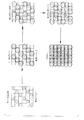
ここで図4〜6を参照するに、ドット構造ドット成長パターンについて述べ、図7に関する議論で以下に述べるライン構造ドット成長パターンの記述とは区別する。本明細書で記述している好適な実施形態は、各々のピクセル位置でグレーレベル・ドットを印刷すべく適合されたグレーレベル印刷ヘッドを用いているが、本発明が各種のスクリーン角およびドットタイプの利用に関して、ハーフトーン・セル内の特定のピクセル位置においてドットを配置する、またはドットを配置しない2値印刷ヘッドにも適していることを理解されたい。上述のように、ピクセル位置はセル・グレーレベルを有するセルにグループ化される。セル内のドットは、セル・グレーレベルが増加する毎に、セル内の少なくとも1個のピクセル、すなわち中核ピクセルにおける1個のドットが、より大きいドットサイズ(またはドット密度)を形成するように形成される。あるタイプの成長パターンの一例において、ドットは所定の順序でセル内のピクセルにおいて逐次形成される。すなわち、下位のセル・グレーレベルにおいてドットが、セル内の第1または中核ピクセル位置に形成されて、セル内で隣接するピクセル位置でドットの形成が始まる前に、セル密度が所望の程度に増大しつつ当該ドットの大きさ(または密度)が最大ドットサイズに達するまで増大するように形成される。その後、セル・グレーレベルを増大させるべく、ピクセル位置において最大ドットサイズに達するまで、隣接するピクセル位置でドットサイズが増大する。セル密度の更なる増大は、隣接するピクセル位置を用いて、ドット成長が中心または中核ピクセル位置から外側へ徐々に進んで中心ピクセル位置を囲むように、ドットの積み重ねと同様に行なわれる。 4 to 6, the dot structure dot growth pattern is described, and is distinguished from the description of the line structure dot growth pattern described below in the discussion regarding FIG. 7. Although the preferred embodiment described herein uses a gray level printhead adapted to print gray level dots at each pixel location, the present invention provides various screen angles and dot types. It should be understood that the present invention is also suitable for binary printheads that place or do not place dots at specific pixel locations within a halftone cell. As described above, pixel locations are grouped into cells having cell gray levels. The dots in a cell are formed so that each time the cell gray level increases, at least one pixel in the cell, that is, one dot in the core pixel, forms a larger dot size (or dot density) Is done. In one example of one type of growth pattern, dots are sequentially formed in pixels within a cell in a predetermined order. That is, at the lower cell gray level, dots are formed at the first or core pixel location in the cell, and the cell density increases to the desired degree before dot formation begins at adjacent pixel locations in the cell. However, the dot size (or density) is formed to increase until the maximum dot size is reached. Thereafter, to increase the cell gray level, the dot size is increased at adjacent pixel locations until the maximum dot size is reached at the pixel location. A further increase in cell density is performed, similar to dot stacking, using adjacent pixel locations so that dot growth progresses outward from the center or core pixel location and surrounds the center pixel location.
あるいは、ハーフトーン・セルのドットの成長パターンは、本明細書にその内容を引用している米国特許第5,258,849号にも記載されている「部分ドット」ドット構造ドット成長パターンであってもよい。 Alternatively, the halftone cell dot growth pattern is the “partial dot” dot structure dot growth pattern described in US Pat. No. 5,258,849, the contents of which are incorporated herein by reference. May be.
米国特許第5,258,849および上に述べた「完全ドット」成長パターンおよび「部分ドット」成長パターンの代わりに、成長パターンは「混合ドット」ドット構造ドット成長パターンとして知られるものであってよい。この場合、中核ピクセル位置におけるドットは、中核ピクセルの1個隣のピクセル位置で成長を開始する前に、最大値より小さい所定のレベルまで成長する。後続するドットの成長は、隣接する1個以上のピクセル位置と共に、中核ピクセルへの追加により行なわれる。 Instead of US Pat. No. 5,258,849 and the “full dot” growth pattern and “partial dot” growth pattern described above, the growth pattern may be what is known as a “mixed dot” dot structure dot growth pattern. . In this case, the dot at the core pixel position grows to a predetermined level below the maximum value before starting to grow at the pixel position next to the core pixel. Subsequent dot growth is done by adding to the core pixel along with one or more adjacent pixel locations.
図4を参照するに、完全ドットタイプの成長パターンの場合における3ビット/ピクセル・グレーハーフトーン・ドット・レイアウトの例が示されている。また、個々のピクセルドットがなり得る大きさに対応する7個の異なるピクセル・ドットサイズを示す。ここに示す例証的な8要素セル30に対して57個の可能なグレーレベルが存在する。グレーレベル12であるセルの形成の例を以下に示す。
Referring to FIG. 4, an example of a 3 bit / pixel gray halftone dot layout in the case of a full dot type growth pattern is shown. Also shown are seven different pixel dot sizes corresponding to the size that an individual pixel dot can be. There are 57 possible gray levels for the illustrative 8-
レベル1において丸で囲まれたピクセルすなわち参照番号1は、レベル1においてドットサイズ1に形成される。1個のセルについてのみ記述するが、他のセル内ピクセルも図4に示すように同じレイアウトまたは成長パターンに従い変更される。セル・グレーレベルがレベル1からレベル2へ増大するにつれて、当該ピクセルのドットがセル・グレーレベル7まで次第に大きくなる。セル・グレーレベルが増大するにつれて、丸で囲まれたピクセルの値がピクセル・サイズ(または密度)1から7まで増大することがわかる。セル30の所望のグレーレベルが7である場合、丸で囲まれたピクセルのドットサイズが7に達すればドットの形成が完了する。しかし、本例ではセル30に対する所望のグレーレベルは12である。グレーレベル7において、丸で囲まれたピクセルは自身の最大ドットサイズに達したことにより、この時点でセル内の他のピクセル位置におけるドットの形成を開始しなければならない。このドットの形成は、レベル1において正方形で囲まれた、参照番号8の隣接ピクセルにおいて開始される。
Pixels circled at
ドット形成処理は継続され、レベルが再びレベル1からレベル5まで増大するにつれて第2のピクセルにおけるドットがより大きく成長する。ピクセルが現在値12に達しているため、形成処理はレベル5で停止する。図5に示すように、ハーフトーン・セル30は現在、ドットサイズ7のドットおよびドットサイズ5のドットを含んでいる。本例から見て、当該形成処理を57個のグレーレベルへ拡張することは容易である。本例は、3ビット/ピクセルに従いドットを形成するプリンタを用いて説明しているが、本発明は、2ビット/ピクセル以上でピクセルを形成可能な任意のグレーレベル印刷ヘッド、並びにドット成長パターンが中央または中核ピクセル位置の周辺にある2値印刷ヘッドでの利用に適している。
The dot formation process continues and the dots at the second pixel grow larger as the level increases from
完全ドットタイプの処理はこのように、優先度が次に高いピクセルについてドットの形成を開始する前に、優先度が最も高いピクセルにおけるドットをそれらの最大許容ドットサイズまで形成するステップを含んでいる。ピクセル優先度が示されている例証的なハーフトーン・ドットマスク32を図6に示す。セルに対して、図4に示すものとは異なるマトリクス・サイズ、セル形状、および優先度を用いることができる。セルの平均が整数である必要がないことを理解した上で、約4×4ピクセルのハーフトーン・セルが知られている。
Full dot type processing thus includes forming dots in the highest priority pixels to their maximum allowable dot size before starting to form dots for the next highest priority pixels. . An illustrative
電子写真処理において、安定したドットを形成し、現れる粒度(ハーフトーン印刷ノイズ)が少ないため、完全ドットタイプ構造処理が好まれている。部分ドットタイプは、完全ドットタイプより多くの詳細情報を含んでいるが、電子写真処理において安定なドットが少ない短所があることが知られている。混合ドットタイプは、グレーレベル・ハーフトーン処理において完全ドットと部分ドットはタイプの両方の利点を組み合わせる。3ビット/ピクセル印刷ヘッドの場合における上述の説明を、より高次のグレーレベルに容易に拡張することができる。4ビット/ピクセルの印刷ヘッドの例において、セル内の各ピクセル位置のグレーレベルは0〜15であってよい。また、8ビット/ピクセル印刷ヘッドの例において、セル内の各ピクセル位置のグレーレベルが0〜255であってよく、またピクセルを印刷するプリンタの解像度が300dpi以上、図2の例は600dpiプリンタの場合、であってよい。 In electrophotographic processing, since a stable dot is formed and the appearing granularity (halftone printing noise) is small, a complete dot type structure processing is preferred. The partial dot type includes more detailed information than the complete dot type, but is known to have a disadvantage in that there are few stable dots in electrophotographic processing. The mixed dot type combines the advantages of both full and partial dots in gray level halftone processing. The above description in the case of a 3 bit / pixel printhead can easily be extended to higher gray levels. In the 4 bit / pixel printhead example, the gray level at each pixel location in the cell may be 0-15. Further, in the example of the 8-bit / pixel print head, the gray level of each pixel position in the cell may be 0 to 255, and the resolution of the printer that prints the pixels is 300 dpi or more, and the example of FIG. If so.
ここで図7を参照し、更に米国特許第5,258,850号を参照するに、セル内のドットの成長パターンが、中心または中核ドットの周囲にドットを成長させるのではなく、ラインまたはライン群に沿って発展または生成していくものであるハーフトーン・セルが示されている。より低いセル密度、例えばセル密度1からセル密度5におけるライン構造ドット成長パターンでは、ドットを有する全てのピクセル位置が露光されて、ドットのラインまたは一連のドットライン(3ドットのラインを図7に示す)が形成される。隣接するドットが重なり合うことでラインが実線ドットラインになるにつれて、図7に示すように実線ラインの各々に隣接する第2のラインを形成することによりセル密度が更に増大する。このように、ライン構造ドット成長パターンは、安定的なドット成長に重点を置く完全または部分ドットあるいは混合タイプ成長構造とは異なり、安定的なライン構造の生成に重点を置くことが分かる。
Referring now to FIG. 7, and further to U.S. Pat. No. 5,258,850, the dot growth pattern in the cell is a line or line rather than a dot growing around the center or core dot. A halftone cell is shown that evolves or generates along the group. In a line-structured dot growth pattern at a lower cell density, eg,
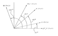
ここで図8を参照するに、本発明の第2の実施形態が示されている。本実施形態では、青色、黒色、および黄色ハーフトーン・スクリーンが、各々75°、45°および0°のスクリーン角を有するドット構造ドット成長パターンを特徴とする。マゼンタおよびシアンのハーフトーン・スクリーンは互いに直交するように配置されていて、シアン・ハーフトーン・スクリーンは15°、マゼンタ・ハーフトーン・スクリーンが105°の角度にある。マゼンタおよびシアンのハーフトーン・スクリーンは共に、各セル内におけるライン構造ドット成長パターンを特徴とするものであり、従ってマゼンタ・スクリーンのハーフトーン・セル内で生成されたラインのパターンは、シアン・スクリーンのハーフトーン・セル内での生成されたラインと直交する。従って、ドット構造ドット成長パターンを使用したハーフトーン・スクリーンの間隔は30°〜45°の範囲であり、ライン構造ドット成長パターンを使用したハーフトーン・スクリーンの間隔は90°であるため、モアレ・アーチファクトも減少して当該スクリーン系では目立たなくなる傾向がある。 Referring now to FIG. 8, a second embodiment of the present invention is shown. In this embodiment, the blue, black, and yellow halftone screens are characterized by a dot structure dot growth pattern having screen angles of 75 °, 45 °, and 0 °, respectively. The magenta and cyan halftone screens are arranged perpendicular to each other, with the cyan halftone screen at an angle of 15 ° and the magenta halftone screen at an angle of 105 °. Both magenta and cyan halftone screens are characterized by a line-structured dot growth pattern within each cell, so the pattern of lines generated within a magenta screen halftone cell is the cyan screen. Orthogonal to the generated line in the halftone cell. Accordingly, the interval of the halftone screen using the dot structure dot growth pattern is in the range of 30 ° to 45 °, and the interval of the halftone screen using the line structure dot growth pattern is 90 °. Artifacts also decrease and tend to be inconspicuous in the screen system.
ここで図9を参照するに、本発明の第3の実施形態が示されている。本実施形態は、4種の原色シアン、マゼンタ、黄色および黒色だけを用い、各々にハーフトーン・スクリーンが関連付けられている。黄色、シアン、黒色、およびマゼンタのハーフトーン・スクリーンは、0°(または45°)、15°、45°および75°の各々既知の角度に配置されている。本実施形態が従来技術と異なるのは、いくつかのハーフトーン・スクリーン、例えば黄色と黒色がドット構造ドット成長パターンにより形成され、他の色、例えばシアンとマゼンタがライン構造ドット成長パターンを特徴とすることである。本例では、シアンおよびマゼンタのハーフトーン・スクリーンにライン構造スクリーンが与えられることにより、これらのラインの2方向の間隔が60°開いて「複ライン」スクリーンを形成し、その白色孔がダイヤモンド形状を有している。この様子は図10に示すダイヤモンド・スクリーンのパターンを参照されたい。図11に、ダイヤモンド構造をなすシアンおよびマゼンタを組み合わせたスクリーンの密度ランプを示す。図9のハーフトーン・スクリーン系は、不快なモアレパターンを最小限に抑えながら、自身を高忠実5色印刷へ拡張する。 Referring now to FIG. 9, a third embodiment of the present invention is shown. This embodiment uses only the four primary colors cyan, magenta, yellow and black, each associated with a halftone screen. The yellow, cyan, black, and magenta halftone screens are arranged at known angles of 0 ° (or 45 °), 15 °, 45 °, and 75 °, respectively. This embodiment differs from the prior art in that some halftone screens, such as yellow and black, are formed by a dot structure dot growth pattern, and other colors, such as cyan and magenta, feature a line structure dot growth pattern. It is to be. In this example, a line structure screen is applied to the cyan and magenta halftone screens, so that the two-way spacing of these lines is 60 ° apart to form a “double line” screen, with the white holes in the diamond shape have. Refer to the diamond screen pattern shown in FIG. FIG. 11 shows a screen density lamp combining cyan and magenta in a diamond structure. The halftone screen system of FIG. 9 expands itself to high fidelity five-color printing while minimizing unpleasant moire patterns.
ここで図12A、12Bを参照するに、5色を用いる本発明の第4および第5の実施形態が示されている。これらの実施形態において、マゼンタ、青色、シアンおよび黒色の4色は各々、例えば図12Aに示すように自身の各ハーフトーン・セル内のライン構造ドット成長パターンを特徴としており、スクリーン角は約22.5°、67.5、°、−22.5°、および−67.5°(より一般的には45°の間隔を開けて)であって、第5のスクリーンである黄色スクリーンは45°に配置されたドットスクリーンであって線数がライン・スクリーンの1.31倍あり、図12Bの実施形態の場合、スクリーン角は、8.13°、45°、98.13°、および135°であって、第5のスクリーンである黄色スクリーンは71.57°に配置されたドットスクリーンで線数がライン・スクリーンの1.12倍である。黄色ハーフトーン・セルは、ライン構造ドット成長パターンを有するスクリーンを備えた2個のハーフトーン・セルの中間の角度を向いている。例えば、図12Aに示すように、黄色ハーフトーン・スクリーンの角度は、マゼンタおよび青色ハーフトーン・スクリーンの角度の中間にある。また、黄色ハーフトーン・スクリーンは、ドット構造ドット成長パターン、および最小のハーフトーン・スクリーンのライン線数の少なくとも1.1倍、好適にはそれ以上のライン線数を特徴とする。ドット構造ドット成長パターンを用いている場合であっても、各セル内のドットは当該色用の各々のスクリーンのスクリーン角に従いラインに沿って整列する傾向があることを理解されたい。更に、「中間に」という用語は、実際の中点から±1°の範囲内にあることを示唆することを理解されたい。典型的なスクリーン線数は、130ライン/インチ(lpi)〜220lpiの範囲にある。 Referring now to FIGS. 12A and 12B, fourth and fifth embodiments of the present invention using five colors are shown. In these embodiments, each of the four colors, magenta, blue, cyan, and black, is characterized by a line-structured dot growth pattern in each of its halftone cells, for example as shown in FIG. 12A, with a screen angle of approximately 22 .5 °, 67.5, °, −22.5 °, and −67.5 ° (more generally at 45 ° intervals), the yellow screen being the fifth screen is 45 For dot screens arranged at ° and 1.31 times as many lines as the line screen, for the embodiment of FIG. 12B, the screen angles are 8.13 °, 45 °, 98.13 °, and 135. The yellow screen, which is the fifth screen, is a dot screen arranged at 71.57 ° and has a line count of 1.12 times that of the line screen. The yellow halftone cell is oriented at an intermediate angle between two halftone cells with a screen having a line structure dot growth pattern. For example, as shown in FIG. 12A, the angle of the yellow halftone screen is halfway between the angles of the magenta and blue halftone screens. The yellow halftone screen is also characterized by a dot structure dot growth pattern and a line number of lines of at least 1.1 times, preferably more than the minimum halftone screen. It should be understood that even when using a dot-structured dot growth pattern, the dots in each cell tend to align along the line according to the screen angle of each screen for that color. Further, it should be understood that the term “in the middle” implies being within ± 1 ° of the actual midpoint. Typical screen line numbers are in the range of 130 lines / inch (lpi) to 220 lpi.
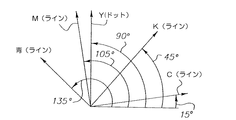
ここで図13を参照するに、5色を用いる本発明の第6の実施形態が示されている。本実施形態において、シアン、黒色、マゼンタおよび青色の各色は、各々のハーフトーン・セル内のライン構造ドット成長パターンを特徴としており、ハーフトーン・セルは各々15°、45°、105°、および135°の角度に配置されている。青色ハーフトーン・セル内に形成されたライン構造が黒色ハーフトーン・セル内に形成されたライン構造と直交することに注意されたい。更に、マゼンタのハーフトーン・セル内に形成されたライン構造は、シアンのハーフトーン・セル内に形成されたライン構造と直交する。従って、不要なモアレパターン・アーチファクトが最小限に抑えられる傾向がある。黄色は、ハーフトーン・セルを90°の角度で用いて、且つドット構造ドット成長パターンを用いて形成される。黄色が主調色(ドミナントカラー)でないため、不要なモアレ・アーチファクト生成の主因とはならない傾向にある。 Referring now to FIG. 13, a sixth embodiment of the present invention using five colors is shown. In this embodiment, each color of cyan, black, magenta and blue is characterized by a line structure dot growth pattern within each halftone cell, where each halftone cell is 15 °, 45 °, 105 °, and It is arranged at an angle of 135 °. Note that the line structure formed in the blue halftone cell is orthogonal to the line structure formed in the black halftone cell. Furthermore, the line structure formed in the magenta halftone cell is orthogonal to the line structure formed in the cyan halftone cell. Therefore, unnecessary moire pattern artifacts tend to be minimized. The yellow color is formed using halftone cells at a 90 ° angle and using a dot structure dot growth pattern. Since yellow is not the main color (dominant color), it tends not to be a main cause of unnecessary moire artifact generation.
ここで図14を参照するに、5色を用いる本発明の第7の実施形態が示されている。黄色および黒色分離用のハーフトーン・スクリーンは各々0°および45°に配置されていて、これらのスクリーンは各々ドット構造ドット成長パターンを用いている。シアンおよびマゼンタの色分解画像は各々15°および75°の角度に自身の各ハーフトーン・スクリーンを有し、これらのハーフトーン・スクリーンは各々ライン構造ドット成長パターンを用いている。シアンおよびマゼンタの色分解画像により60°のライン構造がこのように形成され、この60°のロゼットまたはダイヤモンド・ライン構造は比較的快適である。青色分解画像は、2個のスクリーン間を60°離すべく一方を105°、他方を165°に配置した2個のハーフトーン・スクリーンを用いて形成される。これらの青色分解ハーフトーン・スクリーンの両方ともライン構造を用いている。 Referring now to FIG. 14, a seventh embodiment of the present invention using five colors is shown. The halftone screens for yellow and black separation are arranged at 0 ° and 45 °, respectively, and these screens each use a dot structure dot growth pattern. The cyan and magenta color separation images have their own halftone screens at 15 ° and 75 ° angles, respectively, each of which uses a line structure dot growth pattern. The 60 ° line structure is thus formed by the cyan and magenta color separation images, and this 60 ° rosette or diamond line structure is relatively comfortable. The blue separation image is formed using two halftone screens, one at 105 ° and the other at 165 °, with a 60 ° separation between the two screens. Both of these blue separation halftone screens use line structures.
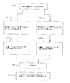
図16のフロー図を参照するに、青色分解用に印刷される実際の画像は、これら2個の青色分解スクリーンの各々における対応ピクセル位置の合成和である。従って図16のフロー図で分かるように、青色分解画像のカラー画像データはカラースキャナ、デジタル・カメラ、メモリまたはコンピュータから入力されても、あるいは他の何らかの色の組合せから生成されてもよく、通常は連続画像情報であって、ステップ100において画像データ・カラーをプリンタの特徴に依存するよう色補正その他の補正を施すことができる。補正された青色分解画像データは、ステップ101、102において2個の異なるハーフトーン・スクリーン角の各々でスクリーン・ジェネレータにより処理される。これを行なうべく、各々のハーフトーン・セルに閾値が割り当てられて各スクリーンに関連付けられ、ライン線数に依存するようにする。入力される青色画像データは閾値と比較されて、特定のピクセル位置i、j(2値印刷の場合)でドットを印刷するか否か、または特定のピクセル位置i、j(グレーレベル印刷の場合)におけるドットのグレーレベルを決定する。各々のピクセル位置i、jについてアルゴリズム的に求められたグレーの値には次いで、ステップ103、104において所定の重み付け値が乗算され、次いで重み付けされた積がステップ105において合算される。ステップ105における合算値は、合成されたピクセル値が受像体シート上のピクセル位置i、jに当該色モジュールにより印刷すべくプリンタへ送られる(ステップ106)。ピクセル値は、当分野で公知のように均一性補正その他のために更に変更することができる。結果的に得られた生成画像は両方のスクリーンの影響を受けており、1個のスクリーン角をなすラインに沿って印刷されたように見える一連のドットまたはライン構造が存在するように、また第2のスクリーン角をなすラインに沿って印刷されたように見える別の一連のドットまたはライン構造が存在する。あるいは、単色の分解や統合を、異なるスクリーン角で別々に処理し、且つ受像体シートに別々印刷して単色でダイヤモンド構造またはロゼット構造の組み合わせを形成することができる。
Referring to the flow diagram of FIG. 16, the actual image printed for the blue separation is the combined sum of the corresponding pixel positions in each of these two blue separation screens. Thus, as can be seen in the flow diagram of FIG. 16, the color image data of the blue separation image may be input from a color scanner, digital camera, memory or computer, or generated from some other color combination, Is continuous image information, and color correction and other corrections can be performed in
ハーフトーン・スクリーンを構成するハーフトーン・セルは画像データに応答して、各ハーフトーン・スクリーン上のさまざまな位置で、ドットを成長させる。その際に、ハーフトーン・スクリーンが互いに60°の角度で形成されているため、互いに60°をなし、各々異なる角度を有するラインに沿ってドットが配置されているように見える。各セルは複数のピクセル位置を含んでいるが、受像部材上の領域に印刷されるグレーレベルを表現するのは当該セル自身であることに注意されたい。各々のハーフトーン・スクリーン101、102は、受像体上のピクセル位置i、jにピクセルを印刷するために通常用いる相手側ピクセル位置を有する。各々のハーフトーン・スクリーンにおける相手側ピクセルは、各スクリーンに関連付けられた重み付け係数が乗算され、次いで合算されて、受像部材上のピクセル位置i、jに印刷すべくプリンタへ送られる。このように青色分解用に形成された合成画像は、青色1色のみである点を除いて図11の密度ランプに関して示したのと同様のダイヤモンド構造を有するロゼットまたはダイヤモンド格子を実質的に表示する二つのライン方向に沿って配置されたピクセルを表わす。
The halftone cells that make up the halftone screen are responsive to the image data to grow dots at various locations on each halftone screen. At this time, since the halftone screens are formed at an angle of 60 ° with respect to each other, the dots appear to be arranged along lines having an angle of 60 ° with each other and different angles. Note that each cell contains multiple pixel locations, but it is the cell itself that represents the gray level that is printed in the area on the image receiving member. Each
この60°のダイヤモンド格子は比較的快適な外観を有することが分かっている。ハーフトーン・スクリーン101、102を合成する際に付与される重みは通常、図17に見られるようなライン構造ドット成長パターンを各々有するハーフトーン・スクリーンの場合に各々0.5であり、好適にはこれらのスクリーンの各々は同じスクリーン線数を有している。しかし、この重み付け係数は一方のスクリーンに他方よりも多くの重みを付与して、一方のスクリーン角またはスクリーン線数を他方より強調することにより調整可能である。図18に示す例を参照されたい。ライン構造ドット成長パターンのスクリーンの場合、各スクリーンに対する重み付け係数は0.4〜0.6の範囲にあって、重み付け係数の和が1.0に等しい。青色または高忠実色分解画像の処理では、互いに上述の60°の角度をなす2個のハーフトーン・スクリーンを使用して、2個のハーフトーン・スクリーンの各々に対してライン構造ドット成長パターンを用いて色分解画像を処理することが好適であるが、ダイヤモンド構造を形成すべく色分解画像を処理する各々の2個のハーフトーン・スクリーン間の適切な角度の範囲は53°〜64°である。 This 60 ° diamond lattice has been found to have a relatively comfortable appearance. The weight given when synthesizing the halftone screens 101, 102 is typically 0.5 for each halftone screen each having a line structure dot growth pattern as seen in FIG. Each of these screens has the same number of screen lines. However, this weighting factor can be adjusted by giving more weight to one screen than the other and emphasizing one screen angle or number of screen lines over the other. See the example shown in FIG. In the case of a screen having a line structure dot growth pattern, the weighting coefficient for each screen is in the range of 0.4 to 0.6, and the sum of the weighting coefficients is equal to 1.0. For the processing of blue or high fidelity color separation images, the two halftone screens that are at the 60 ° angles described above are used to produce a line structure dot growth pattern for each of the two halftone screens. It is preferred to process color separation images using, but a suitable angle range between each two halftone screens processing the color separation images to form a diamond structure is 53 ° to 64 °. is there.
図15を参照するに、5色を用いる本発明の第8の実施形態が示されている。黄色および黒色ハーフトーン・スクリーンの両方が45°に配置されていて、これらのスクリーンの両方共にドット構造ドット成長パターンを用いている。シアンおよびマゼンタのハーフトーン・スクリーンは各々18°および72°に配置されていて、これらのスクリーンの両方がライン構造ドット成長パターンを用いている。青色分解画像は、一方が−18°、他方が−72°に配置された2個のハーフトーン・スクリーンの合成物を用いて、図16のフロー図に示す処理に従って形成され、各々のスクリーンが、図10、11に示すダイヤモンド型ライン構造を形成すべくライン構造ドット成長パターンを用いている。図16のフロー図は、色分解画像の処理にライン構造ドット成長パターンタイプを用いるように記述されているが、相互参照する出願により詳しく述べているように、色分解画像の処理にドット構造ドット成長パターンタイプを用いるために本処理を利用することも可能である。 Referring to FIG. 15, an eighth embodiment of the present invention using five colors is shown. Both yellow and black halftone screens are positioned at 45 °, and both of these screens use a dot structure dot growth pattern. The cyan and magenta halftone screens are arranged at 18 ° and 72 °, respectively, both of which use a line structure dot growth pattern. A blue separation image is formed according to the process shown in the flow diagram of FIG. 16, using a composite of two halftone screens, one placed at −18 ° and the other at −72 °. The line structure dot growth pattern is used to form the diamond type line structure shown in FIGS. The flow diagram of FIG. 16 is described as using the line structure dot growth pattern type for color separation image processing, but as described in more detail in cross-referenced applications, dot structure dots are used for color separation image processing. It is also possible to use this process to use the growth pattern type.
改良されたプリンタおよび印刷方法、並びに画像データを符号化する方法を提示してきた。すなわち、ハーフトーン・セル内で特定の色分解画像をライン構造ドット成長パターン・フォーマットでの表現し、他の色の色分解画像は各々のハーフトーン・セル内でドット構造ドット成長パターンを用いて表現することにより、アーチファクトを最小限に抑えてカラー画像を印刷することができる。本発明は、より広い態様において、少なくとも3種類の異なる色を印刷するために少なくとも3個のハーフトーン・スクリーン・パターンの提供を意図しており、ハーフトーン・スクリーン・パターンのうち2個がドット成長の類似した成長パターンを使用し、ドットの成長がライン構造ドット成長パターン、あるいはドットの成長がドット構造ドット成長パターンのいずれかに従い、第3のハーフトーン・スクリーン・パターンが、前述の2個のハーフトーン・スクリーン・パターンとは異なるドット成長パターンを用いる。各種のハーフトーン・スクリーン・パターンにより形成されて、受像体上に置かれたドットが、同じピクセル位置で互いに重ね合わされて、他の色の多様な陰影を形成することができる。 Improved printers and printing methods, and methods for encoding image data have been presented. That is, a specific color separation image is expressed in a line structure dot growth pattern format in a halftone cell, and color separation images of other colors are displayed using a dot structure dot growth pattern in each halftone cell. By expressing it, it is possible to print a color image with minimal artifacts. The present invention, in a broader aspect, contemplates providing at least three halftone screen patterns for printing at least three different colors, two of the halftone screen patterns being dots. Using a similar growth pattern, the dot growth is either a line structure dot growth pattern or the dot growth is a dot structure dot growth pattern, and the third halftone screen pattern is A dot growth pattern different from the halftone screen pattern is used. Dots formed by various halftone screen patterns and placed on the receiver can be superimposed on each other at the same pixel location to form various shades of other colors.
上述のように、個々のピクセル位置におけるグレーレベル・ドットの生成を好適な実施形態として記述してきたが、本発明はまた、より広い態様において、ハーフトーン・セル内でのライン構造ドット成長パターンおよび/またはハーフトーン・セル内でのドット構造ドット成長パターンの形成に2値ピクセルを利用することも意図している。 As described above, the generation of gray level dots at individual pixel locations has been described as a preferred embodiment, but the present invention, in a broader aspect, also provides line-structured dot growth patterns in halftone cells and It is also contemplated to use binary pixels to form a dot-structured dot growth pattern within a halftone cell.
Claims (47)
第1の所定のハーフトーン・スクリーン角で第1のハーフトーン・セルを生成することにより、画像の第1の色分解画像を表現する情報を生成する第1のハーフトーン・スクリーン・ジェネレータにおいて、第1のハーフトーン・セル内のピクセルがライン構造に配向されていて、第1のハーフトーン・セルのセル密度が逐次増大して、より濃いライン構造として識別される、第1のハーフトーン・スクリーン・ジェネレータと、
第1のハーフトーン・スクリーン角とは異なる第2の所定のハーフトーン・スクリーン角で第2のハーフトーン・セルを生成することにより、画像の第2の色分解画像を表現する情報を生成する第2のハーフトーン・スクリーン・ジェネレータにおいて、第2のハーフトーン・セル内のピクセルがライン構造で表現されていて、第2のハーフトーン・セルのセル密度が逐次増大して、より濃いライン構造として識別され、第2のハーフトーン・セル内に形成されたライン構造が第1のハーフトーン・セル内に形成されたライン構造とは異なる角度である、第2のハーフトーン・スクリーン・ジェネレータと、
第3の所定のハーフトーン・スクリーン角で第3のハーフトーン・セルを生成することにより、画像の第3の色分解画像を表現する情報を生成する第3のハーフトーン・スクリーン・ジェネレータにおいて、第3のハーフトーン・セル内のピクセルがドットで表現されていて、第3のハーフトーン・セルのセル密度が逐次増大して、より濃いライン構造として識別され、第3のハーフトーン・セル画像のドット構造が、一連の平行な第3のラインに沿って並んでいて、前記一連の平行な第3のラインが、第1および第2のハーフトーン・セル内に形成されたライン構造とは異なる角度にある、第3のハーフトーン・スクリーン・ジェネレータとを含む装置。 An apparatus for setting image information for printing an image having at least three different colors,
In a first halftone screen generator that generates information representing a first color separation image of an image by generating a first halftone cell at a first predetermined halftone screen angle; A first halftone cell in which the pixels in the first halftone cell are oriented in a line structure and the cell density of the first halftone cell is sequentially increased to be identified as a darker line structure; A screen generator,
Generating information representing a second color separation image of the image by generating a second halftone cell with a second predetermined halftone screen angle different from the first halftone screen angle. In the second halftone screen generator, the pixels in the second halftone cell are represented by a line structure, and the cell density of the second halftone cell is sequentially increased, resulting in a darker line structure. A second halftone screen generator, wherein the line structure formed in the second halftone cell is at a different angle than the line structure formed in the first halftone cell; ,
In a third halftone screen generator that generates information representing a third color separation image of the image by generating a third halftone cell at a third predetermined halftone screen angle; The pixels in the third halftone cell are represented by dots, and the cell density of the third halftone cell is sequentially increased to be identified as a darker line structure, and the third halftone cell image Are arranged along a series of parallel third lines, and the series of parallel third lines is a line structure formed in the first and second halftone cells. A device comprising a third halftone screen generator at a different angle.
第1の所定のハーフトーン・スクリーン角で第1のハーフトーン・セルを生成することにより、画像の第1の色分解画像を表現する情報を生成するステップであって、第1のハーフトーン・セル内のピクセルをライン構造に配向し、第1のハーフトーン・セルのセル密度が逐次増大して、より濃いライン構造として識別されるようにするステップと、
第1のハーフトーン・スクリーン角とは異なる第2の所定のハーフトーン・スクリーン角で第2のハーフトーン・セルを生成することにより、画像の第2の色分解画像を表現する情報を生成するステップであって、第2のハーフトーン・セル内のピクセルをライン構造で表現し、第2のハーフトーン・セルのセル密度が逐次増大して、より濃いライン構造として識別されるようにして、第2のハーフトーン・セル内に形成されたライン構造が第1のハーフトーン・セル内に形成されたライン構造とは異なる角度にあるようにするステップと、
第3の所定のハーフトーン・スクリーン角で第3のハーフトーン・セルを生成することにより、画像の第3の色分解画像を表現する情報を生成するステップであって、第3のハーフトーン・セル内のピクセルをドットで表現し、第3のハーフトーン・セルのセル密度が逐次増大して、より濃いライン構造として識別されるようにして、第3のハーフトーン・セル画像のドット構造が、一連の平行な第3のラインに沿って配列されていて、前記一連の平行な第3のラインが、第1および第2のハーフトーン・セル内に形成されたライン構造とは異なる角度にあるようにするステップとを含む方法。 A method of setting image information for printing an image having at least three different colors,
Generating information representing a first color separation image of the image by generating a first halftone cell at a first predetermined halftone screen angle comprising: Orienting pixels within the cell into a line structure so that the cell density of the first halftone cell is sequentially increased to be identified as a darker line structure;
Generating information representing a second color separation image of the image by generating a second halftone cell with a second predetermined halftone screen angle different from the first halftone screen angle. A step of representing the pixels in the second halftone cell in a line structure so that the cell density of the second halftone cell is sequentially increased to be identified as a darker line structure; Ensuring that the line structure formed in the second halftone cell is at a different angle than the line structure formed in the first halftone cell;
Generating information representing a third color separation image of the image by generating a third halftone cell at a third predetermined halftone screen angle, the method comprising: The dot structure of the third halftone cell image is represented such that the pixels in the cell are represented by dots and the cell density of the third halftone cell is sequentially increased to be identified as a darker line structure. Arranged along a series of parallel third lines, wherein the series of parallel third lines is at a different angle than the line structure formed in the first and second halftone cells. And a step of making it exist.
少なくとも3種類の異なる色の各々に対してハーフトーン・スクリーン色分解画像データを生成するスクリーン・ジェネレータまたはジェネレータ群を含んでいて、前記スクリーン・ジェネレータまたはジェネレータ群は、所定の各スクリーン角において前記画像を表現するハーフトーン・スクリーンの形式で画像データを生成し、前記3色のうち少なくとも2色の各々に対して第1の種類のドット成長パターンが提供されて異なる密度のハーフトーン・セルを生成すべく動作し、前記3色の第3の色に対して第1の種類のドット成長パターンとは異なる第2の種類のドット成長パターンが提供されて前記3色のうち前記少なくとも2色に対して共通に用いられ、第1の種類の成長パターンはドット構造ドット成長パターンおよびライン構造ドット成長パターンからなるグループから選択され、第2の種類の成長パターンはドット構造ドット成長パターンおよびライン構造ドット成長パターンからなるグループから選択され、更に前記3色の前記少なくとも2色に対するスクリーン角と、前記3色の第3の色に対するスクリーン角の各々が互いに全て異なる装置。 An apparatus for setting image information for printing an image having at least three different colors,
A screen generator or generator group for generating halftone screen color separation image data for each of at least three different colors, wherein the screen generator or generator group includes the image at each predetermined screen angle; The image data is generated in the form of a halftone screen representing the image, and a first type of dot growth pattern is provided for each of at least two of the three colors to generate halftone cells of different densities And a second type of dot growth pattern different from the first type of dot growth pattern is provided for the third color of the three colors, and for the at least two of the three colors. The first type of growth pattern is the dot structure dot growth pattern and line structure. A second growth pattern selected from the group consisting of a dot structure dot growth pattern and a line structure dot growth pattern, and a screen angle for the at least two colors of the three colors; The screen angles for the three third colors are all different from each other.
少なくとも3色の第3の色がドット構造ドット成長パターンにより生成される、請求項22に記載の装置。 23. The apparatus of claim 22, wherein at least two of the three colors are generated by a line structure dot growth pattern and the at least three third colors are generated by a dot structure dot growth pattern.
少なくとも3種類の異なる色の各々に対してハーフトーン・スクリーン色分解画像データを、所定の各スクリーン角において当該画像を表現するハーフトーン・スクリーンの形式で生成するステップを含んでいて、当該3色のうち少なくとも2色の各々に対して第1の種類のドット成長パターンが提供されて異なる密度のハーフトーン・セルを生成すべく動作し、当該3色の第3の色に対して第1の種類のドット成長パターンとは異なる第2の種類のドット成長パターンが提供されて当該3色のうち前記少なくとも2色に対して共通に用いられ、第1の種類の成長パターンはドット構造ドット成長パターンおよびライン構造ドット成長パターンからなるグループから選択され、第2の種類の成長パターンはドット構造ドット成長パターンおよびライン構造ドット成長パターンからなるグループから選択され、更に当該3色の当該少なくとも2色に対するスクリーン角と、当該3色の第3の色に対するスクリーン角の各々が互いに全て異なる方法。 A method of setting image information for printing an image having at least three different colors,
Generating halftone screen color separation image data for each of at least three different colors in the form of a halftone screen representing the image at each predetermined screen angle; A first type of dot growth pattern is provided for each of at least two of the colors to operate to generate different density halftone cells, the first for the third of the three colors A second type of dot growth pattern different from the type of dot growth pattern is provided and used in common for the at least two of the three colors. The first type of growth pattern is a dot structure dot growth pattern. And the second type of growth pattern is a dot structure dot growth pattern and a line structure dot growth pattern. Is selected from the group consisting of the line structure dot growth pattern, further a screen angle with respect to the three colors of the at least two colors, each are all different from each other method of screen angle for the third color of the three colors.
少なくとも3色の第3の色がドット構造ドット成長パターンにより生成される、請求項35に記載の方法。 36. The method of claim 35, wherein at least two of the three colors are generated by a line structure dot growth pattern and the at least three third colors are generated by a dot structure dot growth pattern.
1種類以上の色のハーフトーン・セル用のドット構造ドット成長パターンを用いてハーフトーン・ドットを形成するステップと、
他の色のうち少なくとも2色のハーフトーン・セル用のライン構造ドット成長パターンを用いてハーフトーン・ラインを形成するステップとを含む方法。 A method of generating a multicolor image using a halftone screen,
Forming a halftone dot using a dot growth dot growth pattern for one or more colors of halftone cells;
Forming a halftone line using a line structure dot growth pattern for at least two of the other colors.
Applications Claiming Priority (2)
| Application Number | Priority Date | Filing Date | Title |
|---|---|---|---|
| US10/837,518 US7508549B2 (en) | 2004-04-30 | 2004-04-30 | Method and apparatus for multi-color printing using hybrid dot-line halftone composite screens |
| PCT/US2005/013531 WO2005112431A1 (en) | 2004-04-30 | 2005-04-20 | Hybrid dot-line halftone composite screens |
Publications (2)
| Publication Number | Publication Date |
|---|---|
| JP2007535865A true JP2007535865A (en) | 2007-12-06 |
| JP2007535865A5 JP2007535865A5 (en) | 2008-04-17 |
Family
ID=34966571
Family Applications (1)
| Application Number | Title | Priority Date | Filing Date |
|---|---|---|---|
| JP2007510803A Pending JP2007535865A (en) | 2004-04-30 | 2005-04-20 | Hybrid dot line halftone synthesis screen |
Country Status (5)
| Country | Link |
|---|---|
| US (2) | US7508549B2 (en) |
| EP (1) | EP1741284A1 (en) |
| JP (1) | JP2007535865A (en) |
| IL (1) | IL178357A0 (en) |
| WO (1) | WO2005112431A1 (en) |
Cited By (3)
| Publication number | Priority date | Publication date | Assignee | Title |
|---|---|---|---|---|
| JP2012147236A (en) * | 2011-01-12 | 2012-08-02 | Ricoh Co Ltd | Image processing system and image forming device |
| JP2015521297A (en) * | 2012-04-25 | 2015-07-27 | ヒューマンアイズ テクノロジーズ リミテッド | Method and system for making lenticular articles using a printing blanket |
| US10183182B2 (en) | 2010-08-02 | 2019-01-22 | Guided Therapy Systems, Llc | Methods and systems for treating plantar fascia |
Families Citing this family (13)
| Publication number | Priority date | Publication date | Assignee | Title |
|---|---|---|---|---|
| US7130084B2 (en) * | 2001-01-29 | 2006-10-31 | Seiko Epson Corporation | Electrophotographic apparatus and image processing program |
| US7839537B2 (en) * | 2004-04-30 | 2010-11-23 | Eastman Kodak Company | Method and apparatus for multi-color printing using a rosette or diamond halftone screen for one or more of the colors |
| JP4514132B2 (en) * | 2004-05-28 | 2010-07-28 | 大日本スクリーン製造株式会社 | Threshold matrix generation method for halftone image generation, halftone image generation method and apparatus, and threshold matrix |
| JP2006069123A (en) * | 2004-09-03 | 2006-03-16 | Fuji Photo Film Co Ltd | Ink discharge method, ink discharge device, and image forming device provided with ink discharge device |
| TWI368116B (en) * | 2007-04-04 | 2012-07-11 | Primax Electronics Ltd | Method for generating basic template utilized to form screening mask |
| WO2008132528A1 (en) * | 2007-04-26 | 2008-11-06 | Kodak Graphic Communications Canada Company | Registering patterns of features by adjusting the pitch of image swaths |
| JP4975663B2 (en) * | 2008-03-12 | 2012-07-11 | 大日本スクリーン製造株式会社 | Threshold matrix generation method, halftone image generation method, and halftone image generation apparatus |
| KR101219434B1 (en) * | 2008-04-24 | 2013-01-11 | 삼성전자주식회사 | Image processing apparatus and image processing method |
| US20100027074A1 (en) * | 2008-07-31 | 2010-02-04 | Sharp Laboratories Of America, Inc. | Partition halftone for multi-tone level output device |
| JP4840614B2 (en) * | 2008-09-26 | 2011-12-21 | 富士ゼロックス株式会社 | Image processing apparatus and image processing program |
| JP4962591B2 (en) * | 2010-04-12 | 2012-06-27 | コニカミノルタビジネステクノロジーズ株式会社 | Image forming apparatus |
| EP2773508A4 (en) * | 2011-10-31 | 2015-01-07 | Hewlett Packard Development Co | Method and system for halftone printing |
| JP6102281B2 (en) * | 2013-01-28 | 2017-03-29 | 株式会社リコー | Electrophotographic image output device |
Citations (2)
| Publication number | Priority date | Publication date | Assignee | Title |
|---|---|---|---|---|
| JPH10257336A (en) * | 1997-03-12 | 1998-09-25 | Minolta Co Ltd | Gradation reproducing method and image-forming device |
| JP2002158882A (en) * | 2000-10-30 | 2002-05-31 | Xerox Corp | Method for generating plural non-orthogonal halftone screens |
Family Cites Families (22)
| Publication number | Priority date | Publication date | Assignee | Title |
|---|---|---|---|---|
| EP0079974B1 (en) | 1981-11-20 | 1987-02-04 | DR.-ING. RUDOLF HELL GmbH | Screen system for multicolour printing |
| US4812899A (en) | 1985-01-29 | 1989-03-14 | Harald Kueppers | Printing process where each incremental area is divided into a chromatic area and an achromatic area and wherein the achromatic areas are printed in black and white and the chromatic areas are printed in color sub-sections |
| JPH0413780Y2 (en) * | 1985-03-28 | 1992-03-30 | ||
| DE3537008A1 (en) | 1985-10-17 | 1987-04-23 | Harald Kueppers | METHOD FOR PRODUCING SYSTEMATIC COLOR TABLES OR COLORBOARDS FOR THE SEVEN-COLOR PRINTING AND TABLES OR TABLES PRODUCED BY THIS PROCESS PANEL |
| JPH0691621B2 (en) | 1988-11-24 | 1994-11-14 | 大日本スクリーン製造株式会社 | Halftone image recording method and apparatus |
| JPH0722348B2 (en) | 1989-09-14 | 1995-03-08 | 大日本スクリーン製造株式会社 | Halftone image recording method |
| US5258849A (en) | 1992-06-05 | 1993-11-02 | Eastman Kodak Company | Halftone dot arrangement in gray level halftone printing |
| US5258850A (en) | 1992-06-05 | 1993-11-02 | Eastman Kodak Company | Line screen design for gray scale rendering |
| WO1993026116A2 (en) | 1992-06-05 | 1993-12-23 | Eastman Kodak Company | Method and apparatus for reproducing an image with gray level printing |
| EP0680193B1 (en) | 1994-04-27 | 2000-07-12 | Agfa-Gevaert N.V. | Tone dependent rosette structures in multi layer screening by phase modulation |
| US5734800A (en) | 1994-11-29 | 1998-03-31 | Pantone, Inc. | Six-color process system |
| US5953988A (en) | 1995-09-12 | 1999-09-21 | Agfa Gevaert, N.V. | Screen printing process using rotated screens |
| JP3426851B2 (en) * | 1996-04-30 | 2003-07-14 | 大日本スクリーン製造株式会社 | Dot forming method for multicolor printing |
| US6404508B1 (en) | 1997-03-12 | 2002-06-11 | Minolta Co., Ltd. | Gradation reproduction |
| JPH11308455A (en) | 1998-04-22 | 1999-11-05 | Brother Ind Ltd | Image forming method, image forming device and recording medium |
| US6917443B1 (en) * | 1998-11-18 | 2005-07-12 | Xerox Corporation | Composite halftone screens with stochastically distributed clusters or lines |
| US6307645B1 (en) * | 1998-12-22 | 2001-10-23 | Xerox Corporation | Halftoning for hi-fi color inks |
| US6346993B1 (en) * | 1999-02-05 | 2002-02-12 | Xerox Corporation | Tone-variation-resistant phase-shiftable halftone screen system and method of using |
| US6538677B1 (en) | 2000-05-17 | 2003-03-25 | Heidelberger Druckmaschinen Ag | Apparatus and method for gray level printing |
| US6608641B1 (en) | 2002-06-27 | 2003-08-19 | Nexpress Solutions Llc | Electrophotographic apparatus and method for using textured receivers |
| JP4127628B2 (en) | 2002-07-05 | 2008-07-30 | 富士フイルム株式会社 | Proof image forming method and apparatus |
| US7375866B2 (en) | 2002-09-30 | 2008-05-20 | Kabushiki Kaisha Toshiba | Image processing system and method for screening |
-
2004
- 2004-04-30 US US10/837,518 patent/US7508549B2/en not_active Expired - Fee Related
-
2005
- 2005-04-20 WO PCT/US2005/013531 patent/WO2005112431A1/en not_active Application Discontinuation
- 2005-04-20 JP JP2007510803A patent/JP2007535865A/en active Pending
- 2005-04-20 EP EP05737515A patent/EP1741284A1/en not_active Withdrawn
-
2006
- 2006-09-28 IL IL178357A patent/IL178357A0/en unknown
-
2009
- 2009-02-05 US US12/366,158 patent/US20090141311A1/en not_active Abandoned
Patent Citations (2)
| Publication number | Priority date | Publication date | Assignee | Title |
|---|---|---|---|---|
| JPH10257336A (en) * | 1997-03-12 | 1998-09-25 | Minolta Co Ltd | Gradation reproducing method and image-forming device |
| JP2002158882A (en) * | 2000-10-30 | 2002-05-31 | Xerox Corp | Method for generating plural non-orthogonal halftone screens |
Cited By (4)
| Publication number | Priority date | Publication date | Assignee | Title |
|---|---|---|---|---|
| US10183182B2 (en) | 2010-08-02 | 2019-01-22 | Guided Therapy Systems, Llc | Methods and systems for treating plantar fascia |
| JP2012147236A (en) * | 2011-01-12 | 2012-08-02 | Ricoh Co Ltd | Image processing system and image forming device |
| JP2015521297A (en) * | 2012-04-25 | 2015-07-27 | ヒューマンアイズ テクノロジーズ リミテッド | Method and system for making lenticular articles using a printing blanket |
| US9641702B2 (en) | 2012-04-25 | 2017-05-02 | Humaneyes Technologies Ltd. | Methods and systems of generating a lenticular article using a printing blanket |
Also Published As
| Publication number | Publication date |
|---|---|
| IL178357A0 (en) | 2007-02-11 |
| WO2005112431A1 (en) | 2005-11-24 |
| US20090141311A1 (en) | 2009-06-04 |
| EP1741284A1 (en) | 2007-01-10 |
| US20050243344A1 (en) | 2005-11-03 |
| US7508549B2 (en) | 2009-03-24 |
Similar Documents
| Publication | Publication Date | Title |
|---|---|---|
| JP4827979B2 (en) | How to print a multicolor image | |
| JP2007535865A (en) | Hybrid dot line halftone synthesis screen | |
| US20070046961A1 (en) | Image processing apparatus and method therefor | |
| JP2002082508A (en) | Image forming device | |
| JP4620948B2 (en) | Multicolor image processing system and method | |
| JP2004077940A (en) | Image forming apparatus, image processing apparatus, image forming method and image processing method | |
| US7508557B2 (en) | System and method for processing a multi-colour image | |
| JP4138576B2 (en) | Method and system for processing multicolor images | |
| US20060279788A1 (en) | Automatic generation of supercell halftoning threshold arrays for high addressability devices | |
| US7529005B2 (en) | Method for processing a multi-colour image | |
| JP3733983B2 (en) | Image forming apparatus | |
| US7394572B2 (en) | Method and apparatus for processing of half-tone image | |
| EP1571828B1 (en) | System and method for processing a multi-colour image | |
| EP1571827B1 (en) | Method for processing a multi-colour image | |
| EP1370067B1 (en) | Method and system for processing a multi-colour image | |
| JP2006239879A (en) | Gray-scale representation method and image forming apparatus | |
| JP2008546351A (en) | Method and system for inter-channel clock frequency selection with periodic halftoning | |
| JP2004282245A (en) | Printer adopting tandem system having screen processing section | |
| JP2001028693A (en) | Color image gradation processing system and image processing unit using the same | |
| JPH10243222A (en) | Image processor and image-processing method |
Legal Events
| Date | Code | Title | Description |
|---|---|---|---|
| A521 | Request for written amendment filed |
Free format text: JAPANESE INTERMEDIATE CODE: A523 Effective date: 20080225 |
|
| A621 | Written request for application examination |
Free format text: JAPANESE INTERMEDIATE CODE: A621 Effective date: 20080225 |
|
| A977 | Report on retrieval |
Free format text: JAPANESE INTERMEDIATE CODE: A971007 Effective date: 20100122 |
|
| A131 | Notification of reasons for refusal |
Free format text: JAPANESE INTERMEDIATE CODE: A131 Effective date: 20100202 |
|
| A02 | Decision of refusal |
Free format text: JAPANESE INTERMEDIATE CODE: A02 Effective date: 20100629 |