JP2007532297A - Method and apparatus for improving immersion membrane throughput and operating life - Google Patents
Method and apparatus for improving immersion membrane throughput and operating life Download PDFInfo
- Publication number
- JP2007532297A JP2007532297A JP2007507377A JP2007507377A JP2007532297A JP 2007532297 A JP2007532297 A JP 2007532297A JP 2007507377 A JP2007507377 A JP 2007507377A JP 2007507377 A JP2007507377 A JP 2007507377A JP 2007532297 A JP2007532297 A JP 2007532297A
- Authority
- JP
- Japan
- Prior art keywords
- membrane
- fluid
- gas
- specific gravity
- liquid
- Prior art date
- Legal status (The legal status is an assumption and is not a legal conclusion. Google has not performed a legal analysis and makes no representation as to the accuracy of the status listed.)
- Pending
Links
- 239000012528 membrane Substances 0.000 title claims abstract description 760
- 238000000034 method Methods 0.000 title claims description 166
- 238000007654 immersion Methods 0.000 title claims description 18
- 239000012530 fluid Substances 0.000 claims abstract description 259
- 230000005484 gravity Effects 0.000 claims abstract description 157
- 238000004891 communication Methods 0.000 claims abstract description 91
- 239000007788 liquid Substances 0.000 claims description 500
- XLYOFNOQVPJJNP-UHFFFAOYSA-N water Substances O XLYOFNOQVPJJNP-UHFFFAOYSA-N 0.000 claims description 318
- 229910001868 water Inorganic materials 0.000 claims description 295
- 238000005273 aeration Methods 0.000 claims description 74
- 238000011282 treatment Methods 0.000 claims description 73
- 239000007787 solid Substances 0.000 claims description 70
- 238000004065 wastewater treatment Methods 0.000 claims description 65
- 239000002351 wastewater Substances 0.000 claims description 63
- 239000012466 permeate Substances 0.000 claims description 61
- 238000012545 processing Methods 0.000 claims description 55
- 230000001976 improved effect Effects 0.000 claims description 47
- 238000000926 separation method Methods 0.000 claims description 44
- 230000000630 rising effect Effects 0.000 claims description 36
- 230000008859 change Effects 0.000 claims description 22
- 238000004140 cleaning Methods 0.000 claims description 22
- 230000002776 aggregation Effects 0.000 claims description 21
- 230000009471 action Effects 0.000 claims description 19
- 239000002245 particle Substances 0.000 claims description 17
- 230000006872 improvement Effects 0.000 claims description 16
- 238000005054 agglomeration Methods 0.000 claims description 12
- 239000000463 material Substances 0.000 claims description 11
- 238000003860 storage Methods 0.000 claims description 11
- 239000012510 hollow fiber Substances 0.000 claims description 9
- 230000004044 response Effects 0.000 claims description 9
- 230000000712 assembly Effects 0.000 claims description 7
- 238000000429 assembly Methods 0.000 claims description 7
- 230000001105 regulatory effect Effects 0.000 claims description 5
- 230000003068 static effect Effects 0.000 claims description 4
- 230000004931 aggregating effect Effects 0.000 claims 1
- 239000007789 gas Substances 0.000 description 258
- QGZKDVFQNNGYKY-UHFFFAOYSA-N Ammonia Chemical compound N QGZKDVFQNNGYKY-UHFFFAOYSA-N 0.000 description 112
- QVGXLLKOCUKJST-UHFFFAOYSA-N atomic oxygen Chemical compound [O] QVGXLLKOCUKJST-UHFFFAOYSA-N 0.000 description 92
- 239000010802 sludge Substances 0.000 description 89
- 239000001301 oxygen Substances 0.000 description 86
- 229910052760 oxygen Inorganic materials 0.000 description 86
- 239000002028 Biomass Substances 0.000 description 69
- 230000008569 process Effects 0.000 description 69
- IJGRMHOSHXDMSA-UHFFFAOYSA-N Atomic nitrogen Chemical compound N#N IJGRMHOSHXDMSA-UHFFFAOYSA-N 0.000 description 61
- 230000004907 flux Effects 0.000 description 61
- 229910021529 ammonia Inorganic materials 0.000 description 55
- 238000012360 testing method Methods 0.000 description 52
- 230000000694 effects Effects 0.000 description 47
- 239000000203 mixture Substances 0.000 description 47
- CDBYLPFSWZWCQE-UHFFFAOYSA-L Sodium Carbonate Chemical compound [Na+].[Na+].[O-]C([O-])=O CDBYLPFSWZWCQE-UHFFFAOYSA-L 0.000 description 44
- 238000002156 mixing Methods 0.000 description 44
- CURLTUGMZLYLDI-UHFFFAOYSA-N Carbon dioxide Chemical compound O=C=O CURLTUGMZLYLDI-UHFFFAOYSA-N 0.000 description 40
- 241000196324 Embryophyta Species 0.000 description 35
- OAICVXFJPJFONN-UHFFFAOYSA-N Phosphorus Chemical compound [P] OAICVXFJPJFONN-UHFFFAOYSA-N 0.000 description 33
- 229910052698 phosphorus Inorganic materials 0.000 description 33
- 239000011574 phosphorus Substances 0.000 description 33
- 239000010865 sewage Substances 0.000 description 32
- 238000013461 design Methods 0.000 description 30
- 229910052757 nitrogen Inorganic materials 0.000 description 27
- 238000010586 diagram Methods 0.000 description 26
- 239000008399 tap water Substances 0.000 description 26
- 235000020679 tap water Nutrition 0.000 description 26
- 239000010408 film Substances 0.000 description 25
- 230000007246 mechanism Effects 0.000 description 24
- 238000005498 polishing Methods 0.000 description 23
- 239000008213 purified water Substances 0.000 description 23
- 235000015097 nutrients Nutrition 0.000 description 22
- 230000006870 function Effects 0.000 description 21
- 239000001569 carbon dioxide Substances 0.000 description 20
- 229910002092 carbon dioxide Inorganic materials 0.000 description 20
- 238000000605 extraction Methods 0.000 description 20
- 238000011144 upstream manufacturing Methods 0.000 description 20
- 241000894006 Bacteria Species 0.000 description 19
- 238000006243 chemical reaction Methods 0.000 description 19
- 230000002950 deficient Effects 0.000 description 19
- 244000005700 microbiome Species 0.000 description 19
- ATRRKUHOCOJYRX-UHFFFAOYSA-N Ammonium bicarbonate Chemical compound [NH4+].OC([O-])=O ATRRKUHOCOJYRX-UHFFFAOYSA-N 0.000 description 17
- 229910000013 Ammonium bicarbonate Inorganic materials 0.000 description 17
- 229910002651 NO3 Inorganic materials 0.000 description 17
- NHNBFGGVMKEFGY-UHFFFAOYSA-N Nitrate Chemical compound [O-][N+]([O-])=O NHNBFGGVMKEFGY-UHFFFAOYSA-N 0.000 description 17
- 235000012538 ammonium bicarbonate Nutrition 0.000 description 17
- 239000001099 ammonium carbonate Substances 0.000 description 17
- 230000015572 biosynthetic process Effects 0.000 description 15
- 229920000642 polymer Polymers 0.000 description 15
- 101000916532 Rattus norvegicus Zinc finger and BTB domain-containing protein 38 Proteins 0.000 description 14
- 239000011148 porous material Substances 0.000 description 14
- 239000000047 product Substances 0.000 description 13
- 238000000746 purification Methods 0.000 description 13
- 238000011084 recovery Methods 0.000 description 13
- 229910000831 Steel Inorganic materials 0.000 description 12
- 230000008901 benefit Effects 0.000 description 12
- 230000015556 catabolic process Effects 0.000 description 12
- 238000000354 decomposition reaction Methods 0.000 description 12
- 238000006731 degradation reaction Methods 0.000 description 12
- 230000001546 nitrifying effect Effects 0.000 description 12
- 230000002829 reductive effect Effects 0.000 description 12
- 239000010959 steel Substances 0.000 description 12
- 238000009825 accumulation Methods 0.000 description 11
- 230000001174 ascending effect Effects 0.000 description 11
- 230000012010 growth Effects 0.000 description 11
- 238000005516 engineering process Methods 0.000 description 10
- 229910052751 metal Inorganic materials 0.000 description 10
- 239000002184 metal Substances 0.000 description 10
- 239000000243 solution Substances 0.000 description 10
- OKTJSMMVPCPJKN-UHFFFAOYSA-N Carbon Chemical compound [C] OKTJSMMVPCPJKN-UHFFFAOYSA-N 0.000 description 9
- 238000004220 aggregation Methods 0.000 description 9
- 229910052799 carbon Inorganic materials 0.000 description 9
- 230000007423 decrease Effects 0.000 description 9
- 239000006185 dispersion Substances 0.000 description 9
- 230000007613 environmental effect Effects 0.000 description 9
- 238000005192 partition Methods 0.000 description 9
- 238000004659 sterilization and disinfection Methods 0.000 description 9
- 239000000126 substance Substances 0.000 description 9
- 238000002347 injection Methods 0.000 description 8
- 239000007924 injection Substances 0.000 description 8
- 238000009434 installation Methods 0.000 description 8
- 238000004519 manufacturing process Methods 0.000 description 8
- 230000009467 reduction Effects 0.000 description 8
- 239000002699 waste material Substances 0.000 description 8
- 230000018044 dehydration Effects 0.000 description 7
- 238000006297 dehydration reaction Methods 0.000 description 7
- 238000009826 distribution Methods 0.000 description 7
- 239000006260 foam Substances 0.000 description 7
- 230000033001 locomotion Effects 0.000 description 7
- -1 polyethylene Polymers 0.000 description 7
- 238000012546 transfer Methods 0.000 description 7
- 239000004593 Epoxy Substances 0.000 description 6
- 238000005260 corrosion Methods 0.000 description 6
- 230000007797 corrosion Effects 0.000 description 6
- 238000007872 degassing Methods 0.000 description 6
- 238000011161 development Methods 0.000 description 6
- 235000014113 dietary fatty acids Nutrition 0.000 description 6
- 229910001873 dinitrogen Inorganic materials 0.000 description 6
- 229920001971 elastomer Polymers 0.000 description 6
- 239000000194 fatty acid Substances 0.000 description 6
- 229930195729 fatty acid Natural products 0.000 description 6
- 150000004665 fatty acids Chemical class 0.000 description 6
- 230000000813 microbial effect Effects 0.000 description 6
- 125000001477 organic nitrogen group Chemical group 0.000 description 6
- 230000036961 partial effect Effects 0.000 description 6
- 239000000523 sample Substances 0.000 description 6
- 239000000725 suspension Substances 0.000 description 6
- IOVCWXUNBOPUCH-UHFFFAOYSA-M Nitrite anion Chemical compound [O-]N=O IOVCWXUNBOPUCH-UHFFFAOYSA-M 0.000 description 5
- 239000002253 acid Substances 0.000 description 5
- 239000013078 crystal Substances 0.000 description 5
- 238000006392 deoxygenation reaction Methods 0.000 description 5
- 238000004090 dissolution Methods 0.000 description 5
- 239000010840 domestic wastewater Substances 0.000 description 5
- 238000001914 filtration Methods 0.000 description 5
- 238000005187 foaming Methods 0.000 description 5
- 238000005339 levitation Methods 0.000 description 5
- 238000012423 maintenance Methods 0.000 description 5
- 238000005374 membrane filtration Methods 0.000 description 5
- 239000012071 phase Substances 0.000 description 5
- 150000003839 salts Chemical class 0.000 description 5
- 230000001464 adherent effect Effects 0.000 description 4
- 239000011248 coating agent Substances 0.000 description 4
- 238000000576 coating method Methods 0.000 description 4
- 230000000875 corresponding effect Effects 0.000 description 4
- 238000009792 diffusion process Methods 0.000 description 4
- 235000020188 drinking water Nutrition 0.000 description 4
- 239000003651 drinking water Substances 0.000 description 4
- 238000000855 fermentation Methods 0.000 description 4
- 238000007667 floating Methods 0.000 description 4
- 238000005188 flotation Methods 0.000 description 4
- 239000003365 glass fiber Substances 0.000 description 4
- 230000002706 hydrostatic effect Effects 0.000 description 4
- 239000010842 industrial wastewater Substances 0.000 description 4
- 238000001471 micro-filtration Methods 0.000 description 4
- 230000020477 pH reduction Effects 0.000 description 4
- 150000003904 phospholipids Chemical class 0.000 description 4
- 238000001223 reverse osmosis Methods 0.000 description 4
- 238000004062 sedimentation Methods 0.000 description 4
- 238000009491 slugging Methods 0.000 description 4
- 229920003048 styrene butadiene rubber Polymers 0.000 description 4
- 230000007704 transition Effects 0.000 description 4
- 230000032258 transport Effects 0.000 description 4
- 239000011800 void material Substances 0.000 description 4
- QGZKDVFQNNGYKY-OUBTZVSYSA-N Ammonia-15N Chemical compound [15NH3] QGZKDVFQNNGYKY-OUBTZVSYSA-N 0.000 description 3
- 206010019233 Headaches Diseases 0.000 description 3
- 241000605159 Nitrobacter Species 0.000 description 3
- 241000276498 Pollachius virens Species 0.000 description 3
- 241000700605 Viruses Species 0.000 description 3
- 239000000654 additive Substances 0.000 description 3
- 238000005276 aerator Methods 0.000 description 3
- 229940037003 alum Drugs 0.000 description 3
- 239000012298 atmosphere Substances 0.000 description 3
- 230000033228 biological regulation Effects 0.000 description 3
- 238000004364 calculation method Methods 0.000 description 3
- KRKNYBCHXYNGOX-UHFFFAOYSA-N citric acid Chemical compound OC(=O)CC(O)(C(O)=O)CC(O)=O KRKNYBCHXYNGOX-UHFFFAOYSA-N 0.000 description 3
- 238000005352 clarification Methods 0.000 description 3
- 238000010276 construction Methods 0.000 description 3
- 239000000356 contaminant Substances 0.000 description 3
- 230000001276 controlling effect Effects 0.000 description 3
- 230000003247 decreasing effect Effects 0.000 description 3
- 230000029087 digestion Effects 0.000 description 3
- 229920006334 epoxy coating Polymers 0.000 description 3
- 230000004151 fermentation Effects 0.000 description 3
- 238000005189 flocculation Methods 0.000 description 3
- 230000016615 flocculation Effects 0.000 description 3
- 238000007689 inspection Methods 0.000 description 3
- 230000002262 irrigation Effects 0.000 description 3
- 238000003973 irrigation Methods 0.000 description 3
- 230000014759 maintenance of location Effects 0.000 description 3
- VNWKTOKETHGBQD-UHFFFAOYSA-N methane Chemical compound C VNWKTOKETHGBQD-UHFFFAOYSA-N 0.000 description 3
- 239000010841 municipal wastewater Substances 0.000 description 3
- 238000001728 nano-filtration Methods 0.000 description 3
- 235000016709 nutrition Nutrition 0.000 description 3
- 238000005457 optimization Methods 0.000 description 3
- 239000005416 organic matter Substances 0.000 description 3
- 238000006213 oxygenation reaction Methods 0.000 description 3
- 230000000737 periodic effect Effects 0.000 description 3
- 230000035699 permeability Effects 0.000 description 3
- 230000000704 physical effect Effects 0.000 description 3
- 239000002244 precipitate Substances 0.000 description 3
- 238000003825 pressing Methods 0.000 description 3
- 108090000623 proteins and genes Proteins 0.000 description 3
- 102000004169 proteins and genes Human genes 0.000 description 3
- 230000003134 recirculating effect Effects 0.000 description 3
- 238000000518 rheometry Methods 0.000 description 3
- 238000010008 shearing Methods 0.000 description 3
- 238000003786 synthesis reaction Methods 0.000 description 3
- 238000012384 transportation and delivery Methods 0.000 description 3
- 238000000108 ultra-filtration Methods 0.000 description 3
- QTBSBXVTEAMEQO-UHFFFAOYSA-M Acetate Chemical compound CC([O-])=O QTBSBXVTEAMEQO-UHFFFAOYSA-M 0.000 description 2
- 241000589291 Acinetobacter Species 0.000 description 2
- ZAMOUSCENKQFHK-UHFFFAOYSA-N Chlorine atom Chemical compound [Cl] ZAMOUSCENKQFHK-UHFFFAOYSA-N 0.000 description 2
- 206010021143 Hypoxia Diseases 0.000 description 2
- DGAQECJNVWCQMB-PUAWFVPOSA-M Ilexoside XXIX Chemical compound C[C@@H]1CC[C@@]2(CC[C@@]3(C(=CC[C@H]4[C@]3(CC[C@@H]5[C@@]4(CC[C@@H](C5(C)C)OS(=O)(=O)[O-])C)C)[C@@H]2[C@]1(C)O)C)C(=O)O[C@H]6[C@@H]([C@H]([C@@H]([C@H](O6)CO)O)O)O.[Na+] DGAQECJNVWCQMB-PUAWFVPOSA-M 0.000 description 2
- 229910021578 Iron(III) chloride Inorganic materials 0.000 description 2
- 241000605122 Nitrosomonas Species 0.000 description 2
- GQPLMRYTRLFLPF-UHFFFAOYSA-N Nitrous Oxide Chemical compound [O-][N+]#N GQPLMRYTRLFLPF-UHFFFAOYSA-N 0.000 description 2
- NBIIXXVUZAFLBC-UHFFFAOYSA-N Phosphoric acid Chemical compound OP(O)(O)=O NBIIXXVUZAFLBC-UHFFFAOYSA-N 0.000 description 2
- 208000035415 Reinfection Diseases 0.000 description 2
- 241000607142 Salmonella Species 0.000 description 2
- UIIMBOGNXHQVGW-UHFFFAOYSA-M Sodium bicarbonate Chemical compound [Na+].OC([O-])=O UIIMBOGNXHQVGW-UHFFFAOYSA-M 0.000 description 2
- QAOWNCQODCNURD-UHFFFAOYSA-N Sulfuric acid Chemical compound OS(O)(=O)=O QAOWNCQODCNURD-UHFFFAOYSA-N 0.000 description 2
- 230000000996 additive effect Effects 0.000 description 2
- BFNBIHQBYMNNAN-UHFFFAOYSA-N ammonium sulfate Chemical compound N.N.OS(O)(=O)=O BFNBIHQBYMNNAN-UHFFFAOYSA-N 0.000 description 2
- 229910052921 ammonium sulfate Inorganic materials 0.000 description 2
- 235000011130 ammonium sulphate Nutrition 0.000 description 2
- 230000009286 beneficial effect Effects 0.000 description 2
- 229920001222 biopolymer Polymers 0.000 description 2
- 239000008280 blood Substances 0.000 description 2
- 210000004369 blood Anatomy 0.000 description 2
- 229920002678 cellulose Polymers 0.000 description 2
- 239000001913 cellulose Substances 0.000 description 2
- 238000001311 chemical methods and process Methods 0.000 description 2
- 238000005660 chlorination reaction Methods 0.000 description 2
- 239000000460 chlorine Substances 0.000 description 2
- 229910052801 chlorine Inorganic materials 0.000 description 2
- 238000001816 cooling Methods 0.000 description 2
- 230000002596 correlated effect Effects 0.000 description 2
- 238000012864 cross contamination Methods 0.000 description 2
- 238000002425 crystallisation Methods 0.000 description 2
- 230000008025 crystallization Effects 0.000 description 2
- 238000005202 decontamination Methods 0.000 description 2
- 230000003588 decontaminative effect Effects 0.000 description 2
- 239000001064 degrader Substances 0.000 description 2
- 238000010612 desalination reaction Methods 0.000 description 2
- 238000005553 drilling Methods 0.000 description 2
- 238000001035 drying Methods 0.000 description 2
- 238000000909 electrodialysis Methods 0.000 description 2
- 239000000835 fiber Substances 0.000 description 2
- 235000013305 food Nutrition 0.000 description 2
- 238000005194 fractionation Methods 0.000 description 2
- 239000013505 freshwater Substances 0.000 description 2
- 238000010348 incorporation Methods 0.000 description 2
- 239000011261 inert gas Substances 0.000 description 2
- 150000002500 ions Chemical class 0.000 description 2
- RBTARNINKXHZNM-UHFFFAOYSA-K iron trichloride Chemical compound Cl[Fe](Cl)Cl RBTARNINKXHZNM-UHFFFAOYSA-K 0.000 description 2
- 230000004060 metabolic process Effects 0.000 description 2
- VUZPPFZMUPKLLV-UHFFFAOYSA-N methane;hydrate Chemical compound C.O VUZPPFZMUPKLLV-UHFFFAOYSA-N 0.000 description 2
- 230000004048 modification Effects 0.000 description 2
- 238000012986 modification Methods 0.000 description 2
- 229910017464 nitrogen compound Inorganic materials 0.000 description 2
- 150000002830 nitrogen compounds Chemical class 0.000 description 2
- 230000003647 oxidation Effects 0.000 description 2
- 238000007254 oxidation reaction Methods 0.000 description 2
- 150000002926 oxygen Chemical class 0.000 description 2
- 150000003018 phosphorus compounds Chemical class 0.000 description 2
- 229920002492 poly(sulfone) Polymers 0.000 description 2
- 229920002239 polyacrylonitrile Polymers 0.000 description 2
- 229920000515 polycarbonate Polymers 0.000 description 2
- 239000004417 polycarbonate Substances 0.000 description 2
- 239000004800 polyvinyl chloride Substances 0.000 description 2
- 229920000915 polyvinyl chloride Polymers 0.000 description 2
- 238000001556 precipitation Methods 0.000 description 2
- 238000003672 processing method Methods 0.000 description 2
- 238000005086 pumping Methods 0.000 description 2
- 239000000700 radioactive tracer Substances 0.000 description 2
- 238000011160 research Methods 0.000 description 2
- 230000002441 reversible effect Effects 0.000 description 2
- 229920006395 saturated elastomer Polymers 0.000 description 2
- 238000012216 screening Methods 0.000 description 2
- 239000011734 sodium Substances 0.000 description 2
- 229910052708 sodium Inorganic materials 0.000 description 2
- 239000002689 soil Substances 0.000 description 2
- 239000002910 solid waste Substances 0.000 description 2
- 229910052567 struvite Inorganic materials 0.000 description 2
- 230000008719 thickening Effects 0.000 description 2
- 125000000391 vinyl group Chemical group [H]C([*])=C([H])[H] 0.000 description 2
- 229920002554 vinyl polymer Polymers 0.000 description 2
- 238000004075 wastewater filtration Methods 0.000 description 2
- 241000251468 Actinopterygii Species 0.000 description 1
- QGZKDVFQNNGYKY-UHFFFAOYSA-O Ammonium Chemical compound [NH4+] QGZKDVFQNNGYKY-UHFFFAOYSA-O 0.000 description 1
- KZBUYRJDOAKODT-UHFFFAOYSA-N Chlorine Chemical compound ClCl KZBUYRJDOAKODT-UHFFFAOYSA-N 0.000 description 1
- MYMOFIZGZYHOMD-UHFFFAOYSA-N Dioxygen Chemical compound O=O MYMOFIZGZYHOMD-UHFFFAOYSA-N 0.000 description 1
- 241000588724 Escherichia coli Species 0.000 description 1
- 241000233866 Fungi Species 0.000 description 1
- 229910019142 PO4 Inorganic materials 0.000 description 1
- 229920005372 Plexiglas® Polymers 0.000 description 1
- 239000004698 Polyethylene Substances 0.000 description 1
- ZLMJMSJWJFRBEC-UHFFFAOYSA-N Potassium Chemical compound [K] ZLMJMSJWJFRBEC-UHFFFAOYSA-N 0.000 description 1
- CZMRCDWAGMRECN-UGDNZRGBSA-N Sucrose Chemical compound O[C@H]1[C@H](O)[C@@H](CO)O[C@@]1(CO)O[C@@H]1[C@H](O)[C@@H](O)[C@H](O)[C@@H](CO)O1 CZMRCDWAGMRECN-UGDNZRGBSA-N 0.000 description 1
- 229930006000 Sucrose Natural products 0.000 description 1
- MMDJDBSEMBIJBB-UHFFFAOYSA-N [O-][N+]([O-])=O.[O-][N+]([O-])=O.[O-][N+]([O-])=O.[NH6+3] Chemical compound [O-][N+]([O-])=O.[O-][N+]([O-])=O.[O-][N+]([O-])=O.[NH6+3] MMDJDBSEMBIJBB-UHFFFAOYSA-N 0.000 description 1
- 230000005856 abnormality Effects 0.000 description 1
- 238000005299 abrasion Methods 0.000 description 1
- 229910000147 aluminium phosphate Inorganic materials 0.000 description 1
- 150000001413 amino acids Chemical class 0.000 description 1
- MXZRMHIULZDAKC-UHFFFAOYSA-L ammonium magnesium phosphate Chemical compound [NH4+].[Mg+2].[O-]P([O-])([O-])=O MXZRMHIULZDAKC-UHFFFAOYSA-L 0.000 description 1
- CKMXBZGNNVIXHC-UHFFFAOYSA-L ammonium magnesium phosphate hexahydrate Chemical compound [NH4+].O.O.O.O.O.O.[Mg+2].[O-]P([O-])([O-])=O CKMXBZGNNVIXHC-UHFFFAOYSA-L 0.000 description 1
- 230000003466 anti-cipated effect Effects 0.000 description 1
- 238000013459 approach Methods 0.000 description 1
- 244000062766 autotrophic organism Species 0.000 description 1
- 238000011001 backwashing Methods 0.000 description 1
- 230000001580 bacterial effect Effects 0.000 description 1
- 235000013405 beer Nutrition 0.000 description 1
- 230000004071 biological effect Effects 0.000 description 1
- 230000031018 biological processes and functions Effects 0.000 description 1
- 239000007844 bleaching agent Substances 0.000 description 1
- 230000000903 blocking effect Effects 0.000 description 1
- 238000007664 blowing Methods 0.000 description 1
- 210000001124 body fluid Anatomy 0.000 description 1
- 239000010839 body fluid Substances 0.000 description 1
- 239000006227 byproduct Substances 0.000 description 1
- 150000001722 carbon compounds Chemical class 0.000 description 1
- 238000005266 casting Methods 0.000 description 1
- 230000006037 cell lysis Effects 0.000 description 1
- 230000005465 channeling Effects 0.000 description 1
- 238000009388 chemical precipitation Methods 0.000 description 1
- 239000007795 chemical reaction product Substances 0.000 description 1
- 230000000295 complement effect Effects 0.000 description 1
- 239000012141 concentrate Substances 0.000 description 1
- 230000003750 conditioning effect Effects 0.000 description 1
- 230000000593 degrading effect Effects 0.000 description 1
- 230000001934 delay Effects 0.000 description 1
- 230000001419 dependent effect Effects 0.000 description 1
- 230000008021 deposition Effects 0.000 description 1
- 238000011033 desalting Methods 0.000 description 1
- 238000003795 desorption Methods 0.000 description 1
- 230000001627 detrimental effect Effects 0.000 description 1
- 238000000502 dialysis Methods 0.000 description 1
- 230000009699 differential effect Effects 0.000 description 1
- 238000007865 diluting Methods 0.000 description 1
- 229910001882 dioxygen Inorganic materials 0.000 description 1
- 238000004821 distillation Methods 0.000 description 1
- 230000001614 effect on membrane Effects 0.000 description 1
- 238000011043 electrofiltration Methods 0.000 description 1
- 230000003628 erosive effect Effects 0.000 description 1
- 238000012851 eutrophication Methods 0.000 description 1
- 230000002349 favourable effect Effects 0.000 description 1
- 210000003608 fece Anatomy 0.000 description 1
- 235000003891 ferrous sulphate Nutrition 0.000 description 1
- 239000011790 ferrous sulphate Substances 0.000 description 1
- 239000000706 filtrate Substances 0.000 description 1
- 239000012467 final product Substances 0.000 description 1
- 239000004088 foaming agent Substances 0.000 description 1
- 239000012634 fragment Substances 0.000 description 1
- 239000000446 fuel Substances 0.000 description 1
- 150000004676 glycans Chemical class 0.000 description 1
- PCHJSUWPFVWCPO-UHFFFAOYSA-N gold Chemical compound [Au] PCHJSUWPFVWCPO-UHFFFAOYSA-N 0.000 description 1
- 239000010931 gold Substances 0.000 description 1
- 229910052737 gold Inorganic materials 0.000 description 1
- 239000008187 granular material Substances 0.000 description 1
- JEGUKCSWCFPDGT-UHFFFAOYSA-N h2o hydrate Chemical compound O.O JEGUKCSWCFPDGT-UHFFFAOYSA-N 0.000 description 1
- 230000009931 harmful effect Effects 0.000 description 1
- 230000036541 health Effects 0.000 description 1
- 230000020169 heat generation Effects 0.000 description 1
- 238000010438 heat treatment Methods 0.000 description 1
- 244000059217 heterotrophic organism Species 0.000 description 1
- 238000011065 in-situ storage Methods 0.000 description 1
- 238000012994 industrial processing Methods 0.000 description 1
- 238000011221 initial treatment Methods 0.000 description 1
- 229910052500 inorganic mineral Inorganic materials 0.000 description 1
- 238000003780 insertion Methods 0.000 description 1
- 230000037431 insertion Effects 0.000 description 1
- 238000009413 insulation Methods 0.000 description 1
- 230000003993 interaction Effects 0.000 description 1
- 230000002452 interceptive effect Effects 0.000 description 1
- BAUYGSIQEAFULO-UHFFFAOYSA-L iron(2+) sulfate (anhydrous) Chemical compound [Fe+2].[O-]S([O-])(=O)=O BAUYGSIQEAFULO-UHFFFAOYSA-L 0.000 description 1
- 229910000359 iron(II) sulfate Inorganic materials 0.000 description 1
- JEIPFZHSYJVQDO-UHFFFAOYSA-N iron(III) oxide Inorganic materials O=[Fe]O[Fe]=O JEIPFZHSYJVQDO-UHFFFAOYSA-N 0.000 description 1
- 238000010030 laminating Methods 0.000 description 1
- 230000000670 limiting effect Effects 0.000 description 1
- 239000007791 liquid phase Substances 0.000 description 1
- 238000011068 loading method Methods 0.000 description 1
- 230000007774 longterm Effects 0.000 description 1
- 239000000314 lubricant Substances 0.000 description 1
- 238000007726 management method Methods 0.000 description 1
- 238000005259 measurement Methods 0.000 description 1
- 238000000409 membrane extraction Methods 0.000 description 1
- 238000009285 membrane fouling Methods 0.000 description 1
- 230000002503 metabolic effect Effects 0.000 description 1
- 150000002739 metals Chemical class 0.000 description 1
- 239000011707 mineral Substances 0.000 description 1
- 235000010755 mineral Nutrition 0.000 description 1
- 238000005065 mining Methods 0.000 description 1
- 238000012544 monitoring process Methods 0.000 description 1
- 239000008239 natural water Substances 0.000 description 1
- 238000005121 nitriding Methods 0.000 description 1
- JCXJVPUVTGWSNB-UHFFFAOYSA-N nitrogen dioxide Inorganic materials O=[N]=O JCXJVPUVTGWSNB-UHFFFAOYSA-N 0.000 description 1
- 229910000069 nitrogen hydride Inorganic materials 0.000 description 1
- 239000001272 nitrous oxide Substances 0.000 description 1
- 238000010606 normalization Methods 0.000 description 1
- 230000009965 odorless effect Effects 0.000 description 1
- 238000011022 operating instruction Methods 0.000 description 1
- 150000002894 organic compounds Chemical class 0.000 description 1
- 230000036284 oxygen consumption Effects 0.000 description 1
- 238000006385 ozonation reaction Methods 0.000 description 1
- 238000002161 passivation Methods 0.000 description 1
- 244000052769 pathogen Species 0.000 description 1
- 230000002085 persistent effect Effects 0.000 description 1
- 238000005373 pervaporation Methods 0.000 description 1
- 239000003208 petroleum Substances 0.000 description 1
- 229920003023 plastic Polymers 0.000 description 1
- 239000004033 plastic Substances 0.000 description 1
- 229920000573 polyethylene Polymers 0.000 description 1
- 229920005597 polymer membrane Polymers 0.000 description 1
- 239000004926 polymethyl methacrylate Substances 0.000 description 1
- 229920000098 polyolefin Polymers 0.000 description 1
- 229920001282 polysaccharide Polymers 0.000 description 1
- 239000005017 polysaccharide Substances 0.000 description 1
- 239000011591 potassium Substances 0.000 description 1
- 229910052700 potassium Inorganic materials 0.000 description 1
- 230000001376 precipitating effect Effects 0.000 description 1
- 238000002360 preparation method Methods 0.000 description 1
- 238000002203 pretreatment Methods 0.000 description 1
- 239000011253 protective coating Substances 0.000 description 1
- 238000010926 purge Methods 0.000 description 1
- 239000000376 reactant Substances 0.000 description 1
- 238000007670 refining Methods 0.000 description 1
- 239000012783 reinforcing fiber Substances 0.000 description 1
- 230000008439 repair process Effects 0.000 description 1
- 238000012827 research and development Methods 0.000 description 1
- 239000011347 resin Substances 0.000 description 1
- 229920005989 resin Polymers 0.000 description 1
- 230000036387 respiratory rate Effects 0.000 description 1
- 230000000717 retained effect Effects 0.000 description 1
- 238000005096 rolling process Methods 0.000 description 1
- 239000004576 sand Substances 0.000 description 1
- 238000009287 sand filtration Methods 0.000 description 1
- 239000011555 saturated liquid Substances 0.000 description 1
- 239000013535 sea water Substances 0.000 description 1
- 230000001932 seasonal effect Effects 0.000 description 1
- 239000013049 sediment Substances 0.000 description 1
- 238000012163 sequencing technique Methods 0.000 description 1
- 239000010801 sewage sludge Substances 0.000 description 1
- 108010027322 single cell proteins Proteins 0.000 description 1
- 238000002791 soaking Methods 0.000 description 1
- 239000000344 soap Substances 0.000 description 1
- 235000017557 sodium bicarbonate Nutrition 0.000 description 1
- 229910000030 sodium bicarbonate Inorganic materials 0.000 description 1
- 239000002904 solvent Substances 0.000 description 1
- 230000002269 spontaneous effect Effects 0.000 description 1
- 239000007921 spray Substances 0.000 description 1
- 239000000758 substrate Substances 0.000 description 1
- 239000006228 supernatant Substances 0.000 description 1
- 239000010409 thin film Substances 0.000 description 1
- 230000036962 time dependent Effects 0.000 description 1
- 230000014616 translation Effects 0.000 description 1
- 230000001960 triggered effect Effects 0.000 description 1
- 238000009966 trimming Methods 0.000 description 1
- 241001148471 unidentified anaerobic bacterium Species 0.000 description 1
- 238000004148 unit process Methods 0.000 description 1
- 238000009423 ventilation Methods 0.000 description 1
- 238000012800 visualization Methods 0.000 description 1
- 239000003039 volatile agent Substances 0.000 description 1
- 239000002918 waste heat Substances 0.000 description 1
- 238000003809 water extraction Methods 0.000 description 1
- 238000004804 winding Methods 0.000 description 1
Images


Classifications
-
- B—PERFORMING OPERATIONS; TRANSPORTING
- B01—PHYSICAL OR CHEMICAL PROCESSES OR APPARATUS IN GENERAL
- B01D—SEPARATION
- B01D61/00—Processes of separation using semi-permeable membranes, e.g. dialysis, osmosis or ultrafiltration; Apparatus, accessories or auxiliary operations specially adapted therefor
- B01D61/14—Ultrafiltration; Microfiltration
- B01D61/18—Apparatus therefor
-
- C—CHEMISTRY; METALLURGY
- C02—TREATMENT OF WATER, WASTE WATER, SEWAGE, OR SLUDGE
- C02F—TREATMENT OF WATER, WASTE WATER, SEWAGE, OR SLUDGE
- C02F3/00—Biological treatment of water, waste water, or sewage
- C02F3/02—Aerobic processes
- C02F3/12—Activated sludge processes
- C02F3/1236—Particular type of activated sludge installations
- C02F3/1268—Membrane bioreactor systems
- C02F3/1273—Submerged membrane bioreactors
-
- B—PERFORMING OPERATIONS; TRANSPORTING
- B01—PHYSICAL OR CHEMICAL PROCESSES OR APPARATUS IN GENERAL
- B01D—SEPARATION
- B01D2313/00—Details relating to membrane modules or apparatus
- B01D2313/24—Specific pressurizing or depressurizing means
-
- B—PERFORMING OPERATIONS; TRANSPORTING
- B01—PHYSICAL OR CHEMICAL PROCESSES OR APPARATUS IN GENERAL
- B01D—SEPARATION
- B01D2315/00—Details relating to the membrane module operation
- B01D2315/06—Submerged-type; Immersion type
-
- B—PERFORMING OPERATIONS; TRANSPORTING
- B01—PHYSICAL OR CHEMICAL PROCESSES OR APPARATUS IN GENERAL
- B01D—SEPARATION
- B01D2325/00—Details relating to properties of membranes
- B01D2325/28—Degradation or stability over time
-
- Y—GENERAL TAGGING OF NEW TECHNOLOGICAL DEVELOPMENTS; GENERAL TAGGING OF CROSS-SECTIONAL TECHNOLOGIES SPANNING OVER SEVERAL SECTIONS OF THE IPC; TECHNICAL SUBJECTS COVERED BY FORMER USPC CROSS-REFERENCE ART COLLECTIONS [XRACs] AND DIGESTS
- Y02—TECHNOLOGIES OR APPLICATIONS FOR MITIGATION OR ADAPTATION AGAINST CLIMATE CHANGE
- Y02W—CLIMATE CHANGE MITIGATION TECHNOLOGIES RELATED TO WASTEWATER TREATMENT OR WASTE MANAGEMENT
- Y02W10/00—Technologies for wastewater treatment
- Y02W10/10—Biological treatment of water, waste water, or sewage
Landscapes
- Engineering & Computer Science (AREA)
- Water Supply & Treatment (AREA)
- Chemical & Material Sciences (AREA)
- Chemical Kinetics & Catalysis (AREA)
- Life Sciences & Earth Sciences (AREA)
- Hydrology & Water Resources (AREA)
- Environmental & Geological Engineering (AREA)
- Microbiology (AREA)
- Biodiversity & Conservation Biology (AREA)
- Organic Chemistry (AREA)
- Separation Using Semi-Permeable Membranes (AREA)
- Purification Treatments By Anaerobic Or Anaerobic And Aerobic Bacteria Or Animals (AREA)
- Activated Sludge Processes (AREA)
Abstract
第1面、第2面及び垂直軸とを有する膜であって、所定サイズ未満の分子は第1面と第2面との間を透過可能な膜を含浸漬膜組立体。該膜の第1面と流体連通して、第1比重を有する第1流体を収容する、第1流体コンパートメントと、前記膜の第2面と流体連通して、第2比重を有する第2流体を収容する、第2流体コンパートメントと、第1流体コンパートメントに収容された第1流体と、第2流体コンパートメントに収容された第2流体との間に水頭差を課するための手段と、第2比重を変更するための手段。第2カラム高は、変更された第2比重で前記垂直軸に沿って前記膜の前後で選択された圧力差を発生するために第1カラム高に対して選択される。 A submerged membrane assembly comprising a membrane having a first surface, a second surface, and a vertical axis, wherein molecules having a size less than a predetermined size can pass between the first surface and the second surface. A first fluid compartment in fluid communication with the first surface of the membrane and containing a first fluid having a first specific gravity; and a second fluid in fluid communication with the second surface of the membrane and having a second specific gravity. Means for imposing a head differential between a second fluid compartment, a first fluid contained in the first fluid compartment, and a second fluid contained in the second fluid compartment; Means for changing the specific gravity. The second column height is selected with respect to the first column height to generate a selected pressure difference across the membrane along the vertical axis with a modified second specific gravity.
Description
本発明は、液組成の加工、浄化及び/又は処理(processing, refining, and/or treating liquid compositions)のための方法及び装置に関する。より具体的には、本発明は、選択的、半透性、微孔性その他の分配膜を液組成の加工、浄化及び/又は処理のために利用する膜分離方法及び装置、例えば、膜廃水浄化方法及び装置に関する。 The present invention relates to a method and apparatus for processing, refining, and / or treating liquid compositions of liquid compositions. More specifically, the present invention relates to a membrane separation method and apparatus utilizing selective, semipermeable, microporous or other distribution membranes for processing, purifying and / or treating liquid compositions, such as membrane wastewater. The present invention relates to a purification method and apparatus.
垂直型バイオリアクタに関する背景技術
効率の高い廃水処理は、世界の人口が増加を続けるのでますます重要になってきた。人間が消費その他の用途で必要な水の量は速いペースで増加するが、天然に利用可能な水の量は不変のままである。使用可能な浄水の需要がますます増加することは、廃水の再生(reclamation)を人口の増加及び発展の必須の要素にしている。
Background Art on Vertical Bioreactors Efficient wastewater treatment has become increasingly important as the world's population continues to grow. While the amount of water that humans need for consumption and other uses increases at a rapid pace, the amount of water that is naturally available remains unchanged. Increasing demand for available water purification makes wastewater reclamation an essential element of population growth and development.
米国その他の先進国では、既存の大都市圏が過密になるにつれて、開発業者はこれまで未開発の地域に新たな住宅を建設することを奨励又は要求されている。これらの未開発地域の多くは、消費、灌漑及びこれらに類する目的に十分な水が不足しており、利用可能な水資源の再生及び再利用の必要がある。したがって、これらの地域における開発を成功させるためには、一般には廃水とよばれる、住民が利用した水に由来する下水が再利用の主な標的である。 In the US and other developed countries, as existing metropolitan areas become overcrowded, developers are encouraged or required to build new homes in previously undeveloped areas. Many of these undeveloped areas lack sufficient water for consumption, irrigation and similar purposes, and there is a need to regenerate and reuse available water resources. Therefore, for successful development in these areas, sewage derived from water used by residents, commonly called wastewater, is the main target for reuse.
生活廃水(residential wastewater)は含水量は高いが、人間の排泄物その他の汚物が混在しているために、再利用できる前に十分な加工を要する。既存の下水処理施設から隔離された多くの新規開発地域において生活廃水の再利用を達成するためには、オンサイト、すなわち、現地での廃水処理及び再利用が非常に有利又は必須である。 Residential wastewater has a high water content, but since human excrement and other filth are mixed, sufficient processing is required before it can be reused. On-site, ie, on-site wastewater treatment and reuse is very advantageous or essential to achieve the reuse of domestic wastewater in many newly developed areas isolated from existing sewage treatment facilities.
広範囲のさまざまな異なる廃水処理システムが生活下水その他の範疇の廃水を再利用するために提唱されてきた。特許文献1に開示される1つのかかるシステムは、固形汚物、あるいは、「汚泥(sludge)」を廃水から分離するための単純な沈殿槽(sedimentation tank)を取り込む。沈殿の後、前記汚泥は消化システムに運ばれ、そので清澄な水様液が前記汚泥から分離するように堆積させられる。清澄化された液体は前記沈殿槽に再導入される。残念なことには、このシステムは、多数の欠点をかかえており、非効率である。特に、前記システムは、比較的粗い沈殿システムを含み、該沈殿システムは単に流入する前記汚泥が分離できるようにするだけで、曝気又はなんらかの他のやり方で前記汚泥の処理を促進することはない。
多数の廃水処理工程は、廃水からCOD、リン及び/又は窒素を除去するために、活性化されたバイオマス又は汚泥に含まれる微生物を利用する「生物学的」システムを含む。これらの処理工程は、複数の処理相又は「ゾーン」、すなわち、(1)予備処理領域、(2)一次処理領域及び(3)二次処理領域を含むのが典型的である。予備処理は、主に、未処理廃水から固形無機物を除去することに関する。典型的には、この予備処理は、前記廃棄物(debris)がスクリーン及び/又は沈殿によって除去される2段階処理工程を含む。有機物は液流にのって次の処理のために運ばれる。一次処理は、糞便、食物粒子等のような懸濁固形物を含む前記有機物の一部が浮遊又は沈殿によって除去される物理的な工程を含む。二次処理は、微生物が残存する有機物、窒素及びリンを前記廃水液流から除去するために利用される、生物学的処理工程を含むのが典型的である。微生物増殖及び代謝活性が、制御された増殖条件の利用を通じて利用及び制御される。 Many wastewater treatment processes include “biological” systems that utilize microorganisms contained in activated biomass or sludge to remove COD, phosphorus and / or nitrogen from wastewater. These processing steps typically include a plurality of processing phases or “zones”: (1) a preliminary processing region, (2) a primary processing region, and (3) a secondary processing region. Pretreatment mainly relates to the removal of solid minerals from untreated wastewater. Typically, this pretreatment comprises a two-stage treatment process in which the debris is removed by screen and / or precipitation. The organic matter is carried in the liquid stream for further processing. Primary treatment includes physical steps in which a portion of the organic matter, including suspended solids such as feces, food particles, etc., is removed by floating or sedimentation. The secondary treatment typically includes a biological treatment step that is utilized to remove organic matter, nitrogen and phosphorus from the microorganisms from the wastewater stream. Microbial growth and metabolic activity is utilized and controlled through the use of controlled growth conditions.
大規模な都市又は工業用途では、生物学的処理工程は、前記廃水がバイオマス/汚泥の懸濁液と混合される貯水区(basin)その他の貯水槽を利用するのが典型的である。前記微生物のその後の増殖及び代謝と、得られた前記廃水の処理とは、好気的及び/又は嫌気的/酸素欠乏的条件下で実施される。たいていの大規模都市又は工業用処理システムでは、前記処理工程のさまざまな要素は別々の貯水区又は反応槽(reactor)内で実行される。そのため、1つの処理ステップから次の処理ステップへという連続的な廃水の流れがある。活性微生物を含むバイオマスは、ある工程ステップから別の工程ステップへとリサイクルされる場合がある。例えば、リンの除去、窒素の除去のような特定のタイプの代謝プロセスを実行する傾向を有する特定された微生物のサブグループの増殖を増強するためのかかるバイオマスの条件付けは、特許文献2−5を含む多数の特許の主題であった。生物学的廃水処理の他の要素又は局面の最適化は、特許文献6−29を含むさまざまな特許をもたらした。
有機炭素、窒素及びリン化合物の廃水からの生物学的除去は、処理設備内の特殊な環境条件への配慮を要する。例えば、細菌その他の微生物が(BODとして測定される)有機炭素化合物を二酸化炭素と水とに変換するためには、よく攪拌された好気的環境が必要である。除去されるBOD1ポンド(454g)あたり約1ポンドの酸素が必要である。窒素化合物を窒素ガスと二酸化炭素とに変換するためには、ニトロソーマ(nitrosomas)菌及びニトロバクター(nitrobacter)菌が無機炭素を消費する好気的環境で活動する。(アルカリ度が十分であるとすると)1ポンドのアンモニアのNを硝酸塩のNに変換するために約4.6ポンドの酸素が必要である。その後、条件的細菌が嫌気的環境で活動して、有機炭素を消費し窒素ガスを放出する。1ポンドの硝酸塩のNが窒素ガスに変換されると約2.6ポンドの酸素が回収される。リンを細胞集団に生物学的に結合させるために、揮発性脂肪酸を産生する嫌気的ステップが必要である。これに、嫌気的環境で前記揮発性脂肪酸を代謝して、前記リンをバイオマス内に集中させるのに必要な大量のリンを消費するポリP微生物が続く(非特許文献1)。
理想的には、これら多くの生物学的工程の組み合わせの結果、時々3次処理とよばれる、生物学的富栄養塩除去(BNR)工程ができる。しかし、よく設計された3次処理活動は、要素、工程及び条件の複雑な組み合わせの協働及び順序立てを必要とする。構成要素の生物学的処理ステップのそれぞれは固有の速度で進行し、特異的な環境パラメータを必要とする。効率的な3次処理は、微生物集団を維持し特異的な処理機能を発揮させるために正しい量の特殊な微生物が必要である。 Ideally, the combination of these many biological processes results in a biological nutrient removal (BNR) process, sometimes referred to as a tertiary treatment. However, well-designed tertiary processing activities require the cooperation and sequencing of complex combinations of elements, processes and conditions. Each of the component biological processing steps proceeds at a unique rate and requires specific environmental parameters. Efficient tertiary treatment requires the correct amount of special microorganisms to maintain the microbial population and perform specific processing functions.
3次処理を提供しようとする従来の廃水処理システムは、上向流汚泥床ろ過法(USBF)、回分式活性汚泥法(SBR)及び膜分離活性汚泥法(MSAS)のシステムを含む。回分式活性汚泥法は、従来の活性汚泥処理法の改良である。特許文献30は、SBR法に用いられる垂直長軸エアレータを開示する。SBR法は、囲い込まれたリアクタ内のバイオマスに廃水を順次注入し、反応させ、沈殿させ、デカンテーションすることを含むのが典型的な、区分可能な多数のステップを利用する。本法の最初のステップでは、廃水はバイオマスを含むリアクタに移され、混合液を形成するために混合される。本処理法の反応ステップでは、前記バイオマスの微生物が廃水中の窒素、リン及び/又は有機栄養源を利用し、代謝及び/又は摂取する。後者の反応は、生物の増殖、群集動態及び汚染物質処理を操作するために、嫌気的条件、酸素欠乏条件、好気的条件又はこれらの組み合わせの条件下で実行される。このステージの長さは、廃水の性質、バイオマス濃度その他の因子に依存する。反応サイクルに続いて、前記混合液中のバイオマスは沈殿させられる。汚泥ブランケットがリアクタの底に沈殿し、処理済みの上清は流出する。処理済みで清澄化された水(すなわち流出した水)は次にデカンテーションされ、放流(discharge)される。リアクタ容器は、その後、再注水され、処理工程サイクルが再開される。このようにして、回分式リアクタの工程は、時間的に区切られた作業に基づくが、他の廃水処理工程は、例えば別々の容器での異なる反応の実行による、空間的に区切られた作業に基づく。
さらなる廃水処理設計の多くはエアリフト(air−lift)リアクタを装備するが、該リアクタは、1組の特別に設計されたチャンネルを介する一定の周回パターンでの液体循環を特徴とする、機械的に単純な気液混合流動装置である。液体の動きは、前記リアクタの上向流(昇流、riser)セクションと下向流(降流、downcomer)セクションの平均密度差による。通常、エアリフトリアクタは、異なる液流パターンを有する区別できるゾーンでできている。昇流は、典型的にはがsμが注入されて液体密度差が生じるゾーンで、液相及び気相の両方の上昇流が起こる。リアクタの頂には、気液セパレータセクションがあり、典型的には、該気液セパレータセクションは気泡が液相から脱離する水平液流及び流向逆転の領域である。降流は、気液分散又は脱気された液体が通常は前記昇流に再循環するゾーンである。前記降流ゾーンは、液体の速度が気泡の自由上昇速度より速いか否かに応じて、単相か、並流(cocurrent)2相か、並流−向流(countercurrent)混合2相かのいずれかの降流を示す。前記容器の下端の底部セクションは、降流の出口と昇流の入口とを連絡する。 Many of the additional wastewater treatment designs are equipped with air-lift reactors, which are mechanically characterized by liquid circulation in a constant circular pattern through a set of specially designed channels. It is a simple gas-liquid mixing flow device. The movement of the liquid is due to the average density difference between the upstream (riser) and downstream (downcomer) sections of the reactor. Typically, an airlift reactor is made up of distinct zones with different liquid flow patterns. Upflow is typically a zone where sμ is injected to create a liquid density difference, and both liquid and gas phase upflow occurs. At the top of the reactor is a gas-liquid separator section, which is typically the region of horizontal liquid flow and flow direction reversal where bubbles desorb from the liquid phase. Downstream is a zone where gas-liquid dispersed or degassed liquid is normally recirculated to the upflow. Depending on whether the liquid velocity is faster than the free rise rate of the bubbles, the downflow zone may be single phase, cocurrent two-phase or cocurrent-countercurrent mixed two-phase. Indicates any downfall. The bottom section of the lower end of the vessel communicates the downflow outlet and the upflow inlet.
エアリフト・リアクタは、ICI単細胞タンパク質産生のような微生物発酵法に優占的に用いられてきた。しかし、エアリフト・リアクタを廃水処理に利用するシステムが多数知られている。これらの例のうちには、Betzリアクタ(非特許文献2)と、処理水(effluent)用のディープ・シャフト型バイオリアクタ(非特許文献3を参照せよ。)とがある。
ディープ・シャフト型バイオリアクタの原型の開発に続いて、近年の努力は、廃水処理用垂直長軸バイオリアクタシステムの改良につながった。これらの改良のうち、Pollockに付与された特許文献31−33は、それぞれ生分解性廃水及び/又は汚泥処理用の改良型垂直長軸バイオリアクタシステムを開示する。一般に、これらの垂直軸バイオリアクタシステムは、バイオリアクタと、固液セパレータと、前記バイオリアクタ及び固液セパレータと連絡する介在装置とを含む。前記バイオリアクタは、降流チャンバー及び昇流チャンバーを含む2個または3個以上の垂直で並列又は同心円状のチャンバーを含む循環システムを含む。これらのチャンバーは上端で表面区(surface basin)を通じて連結し、下端では前記降流チャンバーの下端に隣接する共通の「混合ゾーン」を介して連絡する。
前記混合ゾーンに加え、これらのリアクタは、該混合ゾーンの下に配置され、前記混合ゾーンと連絡する「栓状流(plug flow)」ゾーンを備える。上記のとおり、「栓状流」という用語は、前記混合ゾーンから前記リアクタの下端に配置される処理水排出口に向かう全体として下向きの固体粒子の移動をいう。汚泥分解への1つの応用では、前記全体として下向きの移動は、局所的な逆混合(local back mixing)のみを含むことがGuildら(非特許文献4)によって報告されているが、長時間の運転ではゾーン間混合が生じる。
汚物(waste)を含む液体(混合液体、mixed liquor)は、リアクタの底の近傍(例えば、混合ゾーン及び栓状流ゾーンで)酸素含有ガス、通常は空気を注入することによって、前記循環システムを通過するように(すなわち、降流チャンバーと昇流チャンバーとの間、表面区と混合ゾーンとの間を)駆動される。この循環流の一部は前記栓状流ゾーンに導かれ、該栓状流ゾーンの下端で処理水として除去される。廃水処理リアクタでは、空気は典型的にはリアクタの底から5−10フィート(1.524−3.048メートル)上に注入されるのが典型的で、任意的には降流チャンバーの下端の直下に注入される。最深空気注入点は、栓状流ゾーンを、該最深空気注入点より上部の準栓状流ゾーンと、前記最深空気注入点より下部の完全栓状流ゾーンとに分割し、前者は局所的な逆混合が起こるが、後者は混合が起こらないと報告されている。 Liquid containing waste (mixed liquor) is placed in the circulation system by injecting an oxygen-containing gas, usually air, near the bottom of the reactor (eg, in the mixing zone and plug flow zone). Driven through (ie, between the downflow chamber and the upflow chamber, between the surface zone and the mixing zone). A part of this circulating flow is led to the plug-like flow zone and removed as treated water at the lower end of the plug-like flow zone. In wastewater treatment reactors, air is typically injected 5-10 feet (1.524-3.048 meters) from the bottom of the reactor, optionally at the bottom of the downflow chamber. It is injected directly below. The deepest air injection point divides the plug-like flow zone into a quasi-plug flow zone above the deepest air injection point and a full plug-like flow zone below the deepest air injection point. Although backmixing occurs, the latter is reported to not occur.
前記バイオリアクタの起動時には、空気がエアリフトポンプのように昇流チャンバー内に注入され、液体を昇流チャンバーと降流チャンバーとの間で循環させる。降流チャンバー内の液体は、昇流チャンバーの気液混合物よりも密度が高いので、循環を維持するために十分な上向きの力を提供する。 When the bioreactor starts up, air is injected into the upflow chamber like an air lift pump, and the liquid is circulated between the upflow chamber and the downflow chamber. The liquid in the downflow chamber is denser than the gas-liquid mixture in the upflow chamber, thus providing sufficient upward force to maintain circulation.
このようにしていったんバイオリアクタの循環が開始されると、空気注入の全てが混合ゾーン及び/又は栓状流ゾーンに移行される。これらのゾーンから出て行く気泡は昇流チャンバーに導かれ、混合液の下降流速が気泡の上昇速度を上回る降流チャンバーからは排除される。循環中の混合液中の溶存酸素は、汚物の生化学的分解における主要な反応物である。前記混合液が昇流チャンバー内を上昇して静水圧が低い領域に達すると、酸素その他の溶存気体が分離して気泡を形成する。昇流チャンバーからの気液混合物が表面区に入るとき、気体分離が起こる。この目的を促進するために、前記混合液がさらなる処理のために降流チャンバーに再流入する前に、該混合液が前記表面区の大部分を横断して用済みの気体を放出することを強制するために、通常、前記表面区には昇流チャンバーの頂に水平バッフルが取り付けられている。 Once bioreactor circulation is thus initiated, all of the air injection is transferred to the mixing zone and / or plug flow zone. Bubbles exiting these zones are directed to the ascending chamber and are excluded from the descending chamber where the descending flow rate of the mixture exceeds the ascending rate of the bubbles. Dissolved oxygen in the circulating mixture is a major reactant in biochemical degradation of filth. When the mixed liquid rises in the ascending chamber and reaches a region where the hydrostatic pressure is low, oxygen and other dissolved gases are separated to form bubbles. Gas separation occurs when the gas-liquid mixture from the ascending chamber enters the surface zone. To facilitate this purpose, it is necessary for the mixture to release spent gas across most of the surface area before it re-enters the downflow chamber for further processing. To force it, a horizontal baffle is usually attached to the top of the rising chamber in the surface section.
特許文献34は、流入する廃水が流入導管の上向きに導かれた排出口アームを通して昇流チャンバー内の深部に導入される方法を開示する。前記循環流が降流から昇流に逆転すると、変針する速度ヘッドによって乱流ゾーンが降流チャンバーの下端に発生する。この混合ゾーンは、明確ではないが、典型的には深さ15−25フィート(4.572−7.62メートル)である。前記混合ゾーン内の前記混合液体の一部は、上述した前記栓状流ゾーンの下端から処理水ラインに除去された等量の処理水に反応して、前記栓状流の頂に下向きに流れる。バイオリアクタの運転中、バイオリアクタに流入する混合液体と、バイオリアクタから流出する混合液体との流れは、連絡する上部表面区内の液体レベルの変化に対応して制御される。
汚物、溶存酸素、栄養及び(活性微生物群集を含む)バイオマスの間の反応は、実質的には、前記表面区、昇流チャンバー、降流チャンバー及び混合ゾーンで画定されるバイオリアクタの上部循環ゾーンで起こる。前記混合ゾーンの内容物の大多数は、上向きに循環して前記昇流チャンバーに入る。この昇流チャンバーでは、窒素が大半である非溶存気体が、前記リアクタの上部の混合液体の循環を駆動するために必要な気体揚力(gas lift)を提供するのに役立つように膨張する。使用済みの気体が表面区の水平バッフルを横切るときに該使用済み気体は混合液体から放出される。上部循環ゾーンの下に位置する栓状流ゾーンは、混合ゾーンからリアクタの下端の処理水抽出まで下向きに流れる混合液体の最終処理、すなわち、磨き、すなわち研磨(polish、scour)を提供する。 The reaction between filth, dissolved oxygen, nutrients and biomass (including active microbial communities) is essentially the upper circulation zone of the bioreactor defined by the surface zone, the upflow chamber, the downflow chamber and the mixing zone Happens in. The majority of the contents of the mixing zone circulate upward and enter the upflow chamber. In this upflow chamber, the undissolved gas, mostly nitrogen, expands to help provide the gas lift necessary to drive the circulation of the mixed liquid at the top of the reactor. When the spent gas crosses the horizontal baffle in the surface section, the spent gas is released from the mixed liquid. The plug-like flow zone located below the upper circulation zone provides the final treatment, i.e. polish, polish, of the mixed liquid flowing downward from the mixing zone to the treated water extraction at the lower end of the reactor.
注入された酸素を含む気体は、栓状流ゾーンの混合液体に加圧下で容易に溶解するが、該栓状流ゾーンには、混合液体の緩やかな全体として下向きの動きに起因する局所的な逆混合がある。非溶存気体(気泡)は加圧下で非常に乱流の強い混合ゾーンへと上向きに移動する。このゾーンでの気体から液体への転移は非常に効率が高く、リアクタ全体の酸素転移効率は65%を超える。反応産物は二酸化炭素とさらなるバイオマスで、該バイオマスは流入する廃水中に存在する未反応の固形物とともに汚泥(あるいはバイオソリッドbiosolid)を形成する。 The injected oxygen-containing gas readily dissolves in the plug-like flow zone mixed liquid under pressure, but the plug-like flow zone contains local, localized, due to the slow downward movement of the mixed liquid. There is backmixing. Non-dissolved gas (bubbles) moves upward under pressure to a very turbulent mixing zone. The gas-to-liquid transfer in this zone is very efficient and the overall reactor oxygen transfer efficiency exceeds 65%. The reaction products are carbon dioxide and further biomass, which forms sludge (or biosolid biosolid) with unreacted solids present in the incoming wastewater.
BODの好気的分解に加えて、窒素及びリン化合物の生物学的栄養除去(BNR)を従来の廃水処理と結合することがますます重要になっている。高品質の処理済み液体放出の需要が増大するにつれて、本発明によって提供されるような技術の必要性がますます抗しがたくなった。BOD30mg/L及びTSS30mg/Lという以前の第2次生物学的処理基準はもはや多くの管轄区では十分ではなく、今や窒素及びリンについても限度が設定されることがしばしばある。これらの栄養物の効果的な除去は、天然水の富栄養化とこれに起因する生態系の毀損とを防止することを目標とする既存及び策定中の環境法制の観点からは必須である。
In addition to aerobic degradation of BOD, it is becoming increasingly important to combine biological nutrient removal (BNR) of nitrogen and phosphorus compounds with conventional wastewater treatment. As the demand for high quality processed liquid discharges increased, the need for technology such as that provided by the present invention became increasingly difficult. Previous secondary biological treatment standards of
基本的には、窒素除去は酸素存在下で混合液体中に含まれるアンモニアを亜硝酸塩及び硝酸塩に変換することによって達成され、これは好気的硝酸塩化段階として知られる。アンモニアの亜硝酸塩への変換は、ニトロソモナス(Nitrosomonas)菌として知られる微生物によって実行されるが、亜硝酸塩の硝酸塩への変換はニトロバクター菌によって達成される。硝酸塩の窒素への変換は、溶存酸素の欠如した懸濁増殖環境で進行する酸素欠乏脱窒素化段階で起こる。窒素、二酸化炭素及び水が産生され、気体はシステムから排気される。硝化速度は、温度、溶存酸素レベル(D.O.)、pH、固形物滞留時間(SRT)、アンモニア濃度及びBOD/TKN比(全ケルダール(Kjeldahl)窒素、TKNは有機窒素と、アンモニア及びアンモニア塩由来の窒素との和である。)のような相互に依存する廃水パラメータを調節することによって最適化できる。高温及び高溶存酸素レベルは、7.0ないし8.0の範囲のpHレベルと同様に、硝化速度の増大を促進する傾向がある。3.5から5日、好ましくは5−8日の汚泥滞留時間は硝化速度を劇的に上昇させるが、それ以上の長時間では、効率は一定のままである傾向がある。アンモニア濃度の増加は硝化速度を達成可能な最大レベルまで上昇させるが、それ以上高濃度のアンモニアは硝化速度の上昇にはあまり寄与しない。速度は、1.0未満のBOD/TKN比で最大になることも示されている(例えば非特許文献1を参照せよ。) Basically, nitrogen removal is achieved by converting ammonia contained in the mixed liquid into nitrite and nitrate in the presence of oxygen, which is known as the aerobic nitrate stage. The conversion of ammonia to nitrite is performed by a microorganism known as Nitrosomonas, but the conversion of nitrite to nitrate is accomplished by Nitrobacter. The conversion of nitrate to nitrogen occurs in an oxygen-deprived denitrification stage that proceeds in a suspended growth environment lacking dissolved oxygen. Nitrogen, carbon dioxide and water are produced and the gas is exhausted from the system. Nitrification rate is temperature, dissolved oxygen level (DO), pH, solids residence time (SRT), ammonia concentration and BOD / TKN ratio (total Kjeldahl nitrogen, TKN is organic nitrogen, ammonia and ammonia It can be optimized by adjusting interdependent wastewater parameters such as salt-derived nitrogen). High temperatures and high dissolved oxygen levels tend to promote increased nitrification rates, as well as pH levels in the range of 7.0 to 8.0. A sludge residence time of 3.5 to 5 days, preferably 5-8 days, dramatically increases the nitrification rate, but for longer periods, the efficiency tends to remain constant. Increasing ammonia concentration increases the nitrification rate to the maximum achievable level, but higher concentrations of ammonia do not contribute significantly to the increase in nitrification rate. It has also been shown that the speed is maximized at a BOD / TKN ratio of less than 1.0 (see, for example, Non-Patent Document 1).
物理的/生物化学的リン除去は、システムの最初の嫌気的懸濁増殖ゾーンと、揮発性脂肪酸(VFA’s)をリン分解生物(アシネトバクター菌)のエネルギー需要をまかなうために供給する汚泥発酵槽とを必要とするのが典型的である。最近、嫌気的圧送本管(anaerobic force mains)が実質的な生物学的リン除去を可能するのに十分な揮発性脂肪酸を発生できることが報告された。 Physical / biochemical phosphorus removal is the system's first anaerobic suspension growth zone and a sludge fermenter that supplies volatile fatty acids (VFA's) to meet the energy demands of phosphorus-degrading organisms (Acinetobacter) Is typically required. Recently, it has been reported that anaerobic force mains can generate enough volatile fatty acids to allow substantial biological phosphorus removal.
難分解性処理(refractory treatment)及び磨き段階が最終清澄化段階の下流で前記工程に追加される場合がある。多くの廃水流では、有機化合物の大部分(80%−90%)は容易に生分解される。残りの分画はより緩慢に生分解され、「難分解性」とよばれる。従来技術の生物学的栄養除去設計は、例えば、Narnardに付与された特許文献35のような単一の汚泥及び単一の清澄化槽を取り込むが、この場合には、最も酸化速度の遅い化合物を満足させるためにシステム全体の酸化速度を低くしなければならない。
生物学的栄養除去(BNR)システムはさまざまな工程構成をとる場合がある。かかる実施態様の1つが、Barnardに付与された特許文献35に基づく5段階改良バーデンホ(Bardenpho、商標)法である。この方法は、リン、窒素及び有機炭素の除去のための嫌気的、酸素欠乏的及び好気的段階を提供する。24箇所以上のバーデンホ(商標)処理プラントが稼働しており、大半が、それ以前に設計された4段階工程ではなく5段階工程を用いる。これらの施設の大半は、1.0mg/L未満という処理水のリン濃度制限を満足するために補助てきな化学薬品投入を必要とする。この工程を用いるプラントは、さまざまな曝気法、槽構成、ポンプ設備及び汚泥取り扱い法を利用する。非特許文献5。
垂直バイオリアクタ技術の文脈では、Pollock(特許文献36、1997年7月29日発行、引用により本明細書に取り込まれる)は、浮揚選別器を介して冠水したフィルターに連結された垂直バイオリアクタを利用する革新的な方法を開示する。この設計によると、バイオマスを好気的有機炭素高速除去ステップと、これに続く、別の硝化バイオマスを用いる好気的硝化ステップとに分離することによって、反応速度の改良が達成される。これらのステップの後に、有機炭素源を提供し酸素を消費するためのあのゾーン内に流入する混合液体と返送される混合液体又は処理水とを供給することによって作られた酸素欠乏的環境における脱窒化ステップが続く。
リン除去のための嫌気的処理ステップの取り込みは、揮発性脂肪酸産生に要する長時間の発酵のため、別のリアクタ内で実行されるのが典型的である。さらに、捕捉されたリンを再可溶化するおそれがあるため、前記工程の嫌気的部分で産生されたリンが豊富なバイオマスは嫌気的発酵リアクタ産物と接触させるべきではないから、1回混合液体システムにおけるリン除去は実行が困難である。他の場合には、生物学的リン除去は、塩化第二鉄又はミョウバンのような金属塩の添加によって促進される。これらは、リンと化学的に結合させるためにリアクタの好気的ゾーンに直接添加される場合がある。 Incorporation of anaerobic processing steps for phosphorus removal is typically performed in a separate reactor due to the long fermentation required for volatile fatty acid production. In addition, the biomass rich in phosphorus produced in the anaerobic part of the process should not be contacted with the anaerobic fermentation reactor product because it may re-solubilize the captured phosphorus, so it is a single mixed liquid system Phosphorus removal at is difficult to perform. In other cases, biological phosphorus removal is facilitated by the addition of metal salts such as ferric chloride or alum. These may be added directly to the aerobic zone of the reactor for chemical bonding with phosphorus.
したがって、垂直軸リアクタ及びSBRsの組み合わせを含むさまざまな処理システムが3次廃水処理を提供するために使用されて成功した。しかし、これらの3次処理システムは、1回混合液体工程を含み、該工程に関与する特殊な微生物の全てが一緒に混合される。これらは、無機物由来のエネルギーを利用する独立栄養生物(例えばニトロソモナス菌及びニトロバクター菌)と、有機エネルギー源を利用し、好気的BOD除去菌と、生物学的なリン除去菌であるアシネトバクター菌(バイオ−P生物)とを含む、従属栄養生物とを含む。したがって、これらのタイプのシステムの全てにおいて、処理速度は最も処理が遅い微生物、通常はアンモニアを亜硝酸塩に変換するニトロソーマ菌によって制御される。全体としての処理速度が遅いため、これらの1回混合液体システムは長時間曝気システムと呼ばれ、非常にエネルギー集約的である。 Accordingly, various treatment systems including combinations of vertical axis reactors and SBRs have been successfully used to provide tertiary wastewater treatment. However, these tertiary treatment systems include a single mixed liquid process in which all of the special microorganisms involved in the process are mixed together. These include autotrophic organisms that use inorganic-derived energy (for example, nitrosomonas and nitrobacter), aerobic BOD-removing bacteria, and Acinetobacter that are biological phosphorus-removing bacteria using organic energy sources. And heterotrophic organisms including fungi (bio-P organisms). Thus, in all of these types of systems, the rate of treatment is controlled by the slowest microorganism, usually the nitrosoma that converts ammonia to nitrite. Due to the slow overall processing speed, these once mixed liquid systems are called long-time aeration systems and are very energy intensive.
上述の廃水処理技術の発展及び進歩にもかかわらず、広範囲の用途を満足し、既存の廃水処理システムでは満たされない拡張され増強された機能を実行することができる改良された廃水処理システムの緊急な必要性が本技術分野には残っている。例えば、増強された生物学的栄養除去(BNR)を提供し、一部の実施態様では、無制約の土地用途に必要なクラスAバイオソリッドを産生することができる、単純化された廃水処理工程及び装置には長期にわたって満たされていない必要性が本技術分野に存在する。さらに、従来の廃水処理プラントの設置及び運転に随伴する費用および環境への影響を最小にしつつ、これらの拡張された機能を満たす廃水処理システム及び方法について未だに満たされていない必要性が残っている。 In spite of the development and advancement of the above mentioned wastewater treatment technology, there is an urgent need for an improved wastewater treatment system that satisfies a wide range of applications and can perform expanded and enhanced functions that are not met by existing wastewater treatment systems. There remains a need in the art. For example, a simplified wastewater treatment process that provides enhanced biological nutrient removal (BNR) and, in some embodiments, can produce class A biosolids required for unconstrained land use. And there is a long-standing need in the art for devices. Furthermore, there remains an unmet need for wastewater treatment systems and methods that meet these expanded functions while minimizing the cost and environmental impact associated with the installation and operation of conventional wastewater treatment plants. .
膜分離技術に係る背景と、廃水処理用バイオリアクタにおける膜の使用
選択的、半透性又は分配可能な膜を利用する膜分離は、例えば現代の膜廃水浄化法及び装置に用いられるような、液体組成物を加工、精製及び/又は処理するための工業的分離技術の迅速に進化する局面である。一般的な膜分離装置及び方法では、第1の液体組成物、例えば、流入する液体廃水流が膜の第1の表面に接触して、しばしば1種類または2種類以上の駆動力の結果として、第1液体組成物の1種類または2種類以上の構成成分とが膜を通過して第2の液体組成物、例えば、処理水の流れを該膜の第2の表面で形成するのが典型的であり、これによって、分離され、あるいは、分配された第1の液体組成物の1種類または2種類以上の成分が排除され、あるいは、残留する(すなわち、これらの成分は第1の膜表面に分配され、あるいは、保持されて、第1の液体組成物の溶液又は懸濁液中か、あるいは、第1の液体組成物に接触した状態かで残存する。)。
Background on membrane separation technology and use of membranes in wastewater treatment bioreactors Membrane separations utilizing selective, semi-permeable or distributable membranes, such as those used in modern membrane wastewater purification methods and equipment, This is a rapidly evolving aspect of industrial separation technology for processing, purifying and / or processing liquid compositions. In a typical membrane separation apparatus and method, a first liquid composition, for example, an incoming liquid wastewater stream, contacts the first surface of the membrane, often as a result of one or more driving forces, Typically, one or more components of the first liquid composition pass through the membrane to form a second liquid composition, eg, a stream of treated water, on the second surface of the membrane. This eliminates or remains one or more components of the first liquid composition that has been separated or dispensed (ie, these components remain on the surface of the first membrane). Distributed or retained and remains in solution or suspension of the first liquid composition or in contact with the first liquid composition).
本発明の方法及び装置の範囲内で利用可能な液体組成物の加工、浄化及び処理用膜分離技術は、精密濾過、限外濾過、ナノ濾過、逆浸透、電気透析、電気脱塩、浸透気化、膜抽出、膜蒸留、膜剥離(membrane stripping)、膜通気(membrane aeration)その他の膜を利用する方法を含む。用いる膜分離のタイプに応じて、膜機能を有効にし、増強するためのさまざまな駆動力が、単独で、あるいは、本明細書に開示される他の駆動力との組み合わせで利用される場合がある。加圧膜濾過(pressure-driven membrane filtration)は、膜濾過としても知られているが、精密濾過、限外濾過、ナノ濾過及び逆浸透を含み、圧力を駆動力として用いるが、電気透析及び電気脱塩では電気的な駆動力が用いられる。 The liquid composition processing, purification and processing membrane separation techniques available within the method and apparatus of the present invention include microfiltration, ultrafiltration, nanofiltration, reverse osmosis, electrodialysis, electrodesalting, and pervaporation. Membrane extraction, membrane distillation, membrane stripping, membrane aeration and other methods of utilizing membranes. Depending on the type of membrane separation used, various driving forces to enable and enhance membrane function may be utilized alone or in combination with other driving forces disclosed herein. is there. Pressure-drive membrane filtration, also known as membrane filtration, includes microfiltration, ultrafiltration, nanofiltration and reverse osmosis, using pressure as the driving force, but electrodialysis and electrofiltration. In desalting, an electric driving force is used.
膜スケーリング、膜ファウリング、膜劣化その他これらに類することが水流から溶質を除去する効率に負担を課すという不利な効果のため、歴史的には、水処理用膜分離法又はシステムは費用効果が高いとは考えられていなかった。しかし近年、技術の進歩が、膜分離を産業及び生活廃水処理用に適した水様液組成物を処理するためのより商業的に実施可能な技術にした。 Historically, membrane separation methods or systems for water treatment have been cost-effective due to the detrimental effect that membrane scaling, membrane fouling, membrane degradation and the like imposes a burden on the efficiency of removing solutes from water streams. It was not considered expensive. In recent years, however, technological advances have made membrane separation a more commercially viable technique for treating aqueous-like liquid compositions suitable for industrial and domestic wastewater treatment.
膜を用いる固体−液体の分離技術は、廃水処理業界その他の膜分離の技術分野で急速に進歩してきた。初期の膜廃水処理プラントでは膜の予想使用寿命は約5−7年であった。今では、廃水処理用途の膜の使用寿命は8年以上のことがしばしばある。 Membrane-based solid-liquid separation technology has made rapid progress in the wastewater treatment industry and other membrane separation technology areas. In the early membrane wastewater treatment plant, the expected service life of the membrane was about 5-7 years. Now, the service life of membranes for wastewater treatment applications is often over 8 years.
北米その他の世界各地では、バンクーバー、シアトル及びカルガリーのような普段は良い水源を有する都市であっても、給水制限が段々と一般的になってきた。大平原及び砂漠の州の多くの部分では、給水制限は需要になってきた。一部の地域の土壌含水量は既にいわゆる「ダーティー30台」未満である。給水制限の増大の主要な要因は、既存の上水道処理プラントが生活及び商業的な需要の増大を満たすのに十分な量の浄水を製造することができないためである。この問題に関連して、従来は上水道プラントによってより高価で製造されている灌漑用の中程度の質の水の増産のために廃水処理能力を改良する必要性がある。 In North America and other parts of the world, water restrictions have become increasingly common even in cities with normally good water sources such as Vancouver, Seattle and Calgary. In many parts of the Great Plains and desert states, water supply restrictions have become a demand. The soil moisture content in some areas is already less than the so-called “30 dirty” units. A major factor in the increase in water supply restrictions is that existing water treatment plants cannot produce sufficient quantities of purified water to meet the growing domestic and commercial demand. In connection with this problem, there is a need to improve wastewater treatment capacity to increase production of medium quality water for irrigation, which is conventionally produced more expensively by waterworks plants.
現在のところ、1日当たり800万ガロン(8MGD、3.028万m3)を超える多数の膜バイオリアクタプラントが稼働しており、12MGD(4.542万m3)プラントが欧州では建設中と報道されている。新しいホテルは、飲料水用と水洗トイレのような用途の再利用水という2組の配管を有するように設計されている。 Currently, a number of membrane bioreactor plants are operating in excess of 8 million gallons per day (8 MGD, 3.028 million m 3 ), and 12 MGD (45.42 million m 3 ) plants are under construction in Europe. Has been. The new hotel is designed to have two sets of pipes, one for drinking water and one for reused water such as flush toilets.
成長中の北米の大抵の都市は地表の雨水の配管と汚水の配管とを分離している。既存の地表の雨水の配管があるところではどこでも、掘削と新たな配管配設に伴う高い費用をかけることなく、より太い雨水の配管の内部に直径の細い再利用水の返送配管を設置することが可能である。この開発モデルでは、雨が降るときには再利用水は不要だから、交差汚染は意味のある問題ではない。さらに、再利用水の配管は、雨水よりも品質の高い水で加圧されている。より安価な再利用水は、道路、ゴルフ場、公園、芝農園(sod farm)養樹園(nursery)、芝生当の灌漑及び/又は維持用に市内の大抵の場所に配水することができる。 Most growing cities in North America separate surface rainwater piping from sewage piping. Wherever existing surface stormwater piping is located, install recycled water return pipes with smaller diameter inside thicker stormwater piping without the high costs associated with drilling and new piping installation Is possible. In this development model, cross-contamination is not a significant issue because it does not require reused water when it rains. Furthermore, the reused water piping is pressurized with water of higher quality than rainwater. Less expensive reclaimed water can be distributed to most places in the city for irrigation and / or maintenance of roads, golf courses, parks, sod farms, nurseries, lawns .
代替的には、3次処理を提供する改良型垂直長軸バイオリアクタを使うような小規模の処理プラントが、都市化地区中に戦略的に配置され、民有で市町村の関与なしに運転される場合がある。需要の少ない期間には前記小規模処理プラントは地表の雨水廃水溝に直接放流される場合があり、これによって、市町村営プラントへの負担を実質的に軽減する。 Alternatively, small processing plants, such as using an improved vertical long-axis bioreactor that provides tertiary treatment, are strategically placed in urbanized areas and operated privately and without municipal involvement There is a case. During periods of low demand, the small-scale treatment plant may be discharged directly into the surface stormwater drainage channel, thereby substantially reducing the burden on municipal plants.
前記改良型垂直長軸バイオリアクタは、それぞれが全体の処理の特定の一部に専用の順次的なゾーンを用いる単一の一体型バイオリアクタにおいてBNR処理を達成する。したがって、各ゾーンは個別に最適化される場合がある。 The improved vertical long axis bioreactor achieves BNR processing in a single integrated bioreactor, each using sequential zones dedicated to a specific part of the overall process. Thus, each zone may be optimized individually.
膜分離、加工及び処理技術の技術的進歩は速いペースで起こっている。膜の透過流束(膜表面積平方フィートあたりの流速)が増大する一方で、平方フィートあたりの費用は着実に低下する。さらに、現代の処理加工プラントで使用する膜の費用は低下してきており、今後10年間にわたってより著しく低下するであろう。これらの要因はまとめて他の工程のうちでも再利用廃水の処理における膜の利用を奨励するであろう。例えば、サンディエゴでの最近の膜バイオリアクタ(MBR)パイロットプラントの試みは、1MGD規模及び5MGD規模のプラントで製造するとき、それぞれ1000ガロン(3.785立方メートル)あたり3.05ドル及び1.92ドルかかるであろうことが示される。この費用は、資本の減価償却と、通年運転ベースの運転及び維持の費用とを含む。シアトルの少なくとも1箇所のゴルフ場は季節的需要ベースで飲料水100立方フィート(2.832立方メートル)あたり3.96ドル支払っている。 Technological advances in membrane separation, processing and processing technologies are taking place at a fast pace. While the permeation flux of the membrane (flow rate per square foot of membrane surface area) increases, the cost per square foot decreases steadily. In addition, the cost of membranes used in modern processing plants has declined and will decline significantly over the next decade. These factors together will encourage the use of membranes in the treatment of recycled wastewater, among other processes. For example, recent membrane bioreactor (MBR) pilot plant attempts in San Diego are $ 3.05 and $ 1.92 per 1000 gallons (3.785 cubic meters) when manufactured in 1 MGD and 5 MGD scale plants, respectively. It will be shown that this would be the case. This cost includes capital depreciation and full year operating and maintenance costs. At least one golf course in Seattle pays $ 3.96 per 100 cubic feet of drinking water on a seasonal demand basis.
膜バイオリアクタは、その性能を維持するためには定期的なクリーニングが必要である。クリーニングの頻度は、膜のタイプとその運転環境とに依存するが、典型的には数ヶ月に1回の頻度である。既存のリアクタは膜のクリーニング期間中は運転休止するのが典型的であり、廃水処理能力の一時的で周期的に起こる損失の原因となる。さらに、クリーニングはしばしば高価で特殊な化学薬品の使用を伴い、使用及び廃棄の環境規制を遵守する必要がある。 Membrane bioreactors require periodic cleaning to maintain their performance. The frequency of cleaning depends on the type of membrane and its operating environment, but is typically once every few months. Existing reactors typically shut down during membrane cleaning, causing temporary and periodic loss of wastewater treatment capacity. In addition, cleaning often involves the use of expensive and specialized chemicals and requires compliance with environmental regulations for use and disposal.
改良型垂直長軸バイオリアクタは他のバイオリアクタと比較して独特な利点を提供するが、かかるリアクタに膜を取り込む方法及び装置の必要性がある。 While improved vertical long axis bioreactors offer unique advantages compared to other bioreactors, there is a need for methods and apparatus for incorporating membranes into such reactors.
本発明の諸局面はこれらの必要性を満たし、以下の説明と添付する図面とから明らかになるであろうさらなる目的及び利点を達成する。 Aspects of the present invention meet these needs and achieve additional objects and advantages that will become apparent from the following description and the accompanying drawings.
発明の概要
本発明は、廃水の生物学的処理用の浸漬膜のスループット及び運転寿命が改良され、該膜のクリーニング及び保守の間の期間が延長された方法及び装置を提供する。より具体的には、本発明は、選択的、半透性、微孔性その他の分配膜を液体組成物の加工、浄化及び/又は処理に利用する膜分離法及び装置、例えば、膜廃水浄化方法及び装置に関する。本発明の他の局面は、膜の両側の間で実質的に均一な圧力差を発生させることによって液体中の気体拡散を改善する。
SUMMARY OF THE INVENTION The present invention provides a method and apparatus in which the throughput and operating life of a submerged membrane for biological treatment of wastewater is improved and the period between cleaning and maintenance of the membrane is extended. More specifically, the present invention relates to membrane separation methods and apparatus that utilize selective, semi-permeable, microporous or other distribution membranes for processing, purifying and / or treating liquid compositions, such as membrane wastewater purification. The present invention relates to a method and an apparatus. Another aspect of the invention improves gas diffusion in the liquid by creating a substantially uniform pressure differential between the two sides of the membrane.
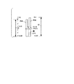
本発明の1つの局面では、浸漬膜組立体と、関連する方法及び装置が提供される。浸漬した前記組立体は、通常平面的な膜の相対する面を含む少なくとも第1面及び第2面を有する膜とを含むのが典型的である。一部の実施態様では、前記膜の相対する表面は正方形又は長方形であり、前記膜は垂直な軸(例えば、正方形の膜の一辺か、長方形の膜の長辺かによって定義される垂直)を有する。前記膜は所定のサイズ未満の分子によって第1面と第2面との間が透過可能である。 In one aspect of the present invention, an immersion membrane assembly and associated methods and apparatus are provided. The submerged assembly typically includes a membrane having at least a first surface and a second surface that include opposing surfaces of a generally planar membrane. In some embodiments, the opposing surfaces of the membrane are square or rectangular, and the membrane has a vertical axis (eg, a vertical defined by one side of a square membrane or the long side of a rectangular membrane). Have. The membrane is permeable between the first surface and the second surface by molecules less than a predetermined size.
本発明の他の局面の範囲内で、前記浸漬膜組立体は、第1液体コンパートメントと含むが、第1液体コンパートメントは前記膜の第1面と液体連通している第1比重を有する第1液体を含む。前記組立体は第2液体コンパートメントも含むが、第2液体コンパートメントは、前記膜の第2面と液体連通している第2比重を有する第2液体を含む。 Within another aspect of the present invention, the submerged membrane assembly includes a first liquid compartment, the first liquid compartment having a first specific gravity in liquid communication with the first surface of the membrane. Contains liquid. The assembly also includes a second liquid compartment, the second liquid compartment including a second liquid having a second specific gravity in liquid communication with the second surface of the membrane.
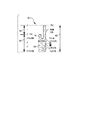
さらに前記膜組立体は、第1コンパートメント内に収容される第1液体と、第2コンパートメントに収容される第2液体との間の水頭(hydraulic head)の差を課するための手段と、第2比重を変化させるための手段とを含むのが典型的である。前記水頭の差を課するための手段は第1液体コンパートメント及び第2液体コンパートメントを含む場合があり、第1液体コンパートメントは第1カラム高を画定し、第2液体コンパートメントは第2カラム高を画定する。第2カラム高は、第1比重と及び変化した第2比重とで前記膜の垂直軸に沿って該膜の両側で選択された圧力差を生じるように、第1カラム高に対して選択される場合がある(すなわち、第2比重は前記第2比重を変化させる手段の動作によって、最初の第2比重値から変化後の第2比重値へと変更される。)。第1及び第2カラム高は、重力と、第1及び第2液体コンパートメントの構成及び設計とによってのみ確立される場合がある(前記膜の垂直軸との関係で第1液体コンパートメントの液体カラム高より低い位置に第2液体コンパートメントのアウトフロー又はオーバーフロー用のポート又は開口を設けることによるのが典型的である。)。代替的には、前記水頭の差を課する手段は、第1液体コンパートメントと第2液体コンパートメントとの間の圧力差を加える手段を含む場合がある。例えば、第1コンパートメント内の第1液体の液圧と比較してより低い圧力を第2液体に発生させるために、陰圧発生手段又は真空が第2コンパートメント又は第2液体に適用される場合がある。代替的には、第2コンパートメント内の第2液体の液圧と比較してより高い圧力を発生させるために、陽圧発生手段又は加圧装置が第1コンパートメント又は第1液体に適用される場合がある。 The membrane assembly further includes means for imposing a hydraulic head difference between the first liquid contained in the first compartment and the second liquid contained in the second compartment; And means for changing the specific gravity. The means for imposing the head differential may include a first liquid compartment and a second liquid compartment, the first liquid compartment defining a first column height and the second liquid compartment defining a second column height. To do. The second column height is selected with respect to the first column height such that the first specific gravity and the changed second specific gravity produce a selected pressure difference across the membrane along the vertical axis of the membrane. (In other words, the second specific gravity is changed from the first second specific gravity value to the second specific gravity value after the change by the operation of the means for changing the second specific gravity). The first and second column heights may only be established by gravity and the configuration and design of the first and second liquid compartments (the liquid column height of the first liquid compartment in relation to the vertical axis of the membrane. (Typically by providing a port or opening for outflow or overflow of the second liquid compartment at a lower location). Alternatively, the means for imposing the water head difference may include means for applying a pressure difference between the first liquid compartment and the second liquid compartment. For example, a negative pressure generating means or vacuum may be applied to the second compartment or the second liquid to generate a lower pressure on the second liquid compared to the hydraulic pressure of the first liquid in the first compartment. is there. Alternatively, a positive pressure generating means or pressurizing device is applied to the first compartment or the first liquid in order to generate a higher pressure compared to the hydraulic pressure of the second liquid in the second compartment. There is.
本発明のさまざまな実施態様のなかには、第2比重を変化させる手段が、第2コンパートメント内の第2液体の中に気体を直接的又は間接的に導入する手段を含む場合がある。例えば、気体は、第2液体に直接溶解されたり、第2液体の中に気泡の形で導入される場合があり、これによって、第2比重を、所望の変化後の第2比重値に減少させる。典型的には、第1液体は溶存気体を含み、液体状態か、あるいは、微小気泡又はより大きな気泡の状態かのいずれかで、第1側から第2側へと前記膜を介して透過することによって、気体が第1液体から第2液体へと導入される。一部の実施態様では、第1液体中の溶存気体(例えば、空気又は酸素)は、前記膜の第1面と第2面との間を透過して、第2面で、あるいは第2面の近傍で凝集して気泡を形成し、該気泡は第2液体に取り込まれる。前記気体を導入する手段が第1液体から第2液体へと溶存気体を転送することを含むとき、前記気体は膜の第2面で、あるいは、第2面の近傍で凝集する場合があり、これは、第1面と第2面との間でか、第2液体コンパートメント内の第2面でかの凝集及び/又は第2液体の中への気体の溶解を含む場合がある。代替的には、前記気体を導入する手段は、気体の溶解及び気泡の形成を伴うことなく第1液体から第2液体へと溶存気体の導入を達成することができるが、これは代替的には気体導入後に起こる場合もあれば、全く起こらない場合もある。さらなる実施態様では、第1液体の溶存気体は前記膜を通過することによって与えられる機械的作用又は前記膜の両側での圧力差に応答して凝集するか、第1液体と第2液体との間の溶存気体レベルの差に応答して第2液体中で凝集するかの場合がある。他の一部の実施態様では、前記第2比重を変化させる手段は、第2液体の中へ気体を導入するために第2液体コンパートメントと結合された気体導入ポートを含む場合がある。気体は、この気体導入ポートを通じて、加圧気体の状態か、他の状態、例えば、第2液体と混合される気体が飽和した液体を導入することによって、第2液体の中に導入される場合がある。 In various embodiments of the present invention, the means for changing the second specific gravity may include means for directly or indirectly introducing a gas into the second liquid in the second compartment. For example, the gas may be dissolved directly in the second liquid or introduced into the second liquid in the form of bubbles, thereby reducing the second specific gravity to the second specific gravity value after the desired change. Let Typically, the first liquid contains dissolved gas and permeates through the membrane from the first side to the second side either in the liquid state or in the form of microbubbles or larger bubbles. As a result, gas is introduced from the first liquid into the second liquid. In some embodiments, dissolved gas (e.g., air or oxygen) in the first liquid permeates between the first and second surfaces of the membrane to form the second surface or the second surface. In the vicinity of to form bubbles to be taken into the second liquid. When the means for introducing the gas includes transferring dissolved gas from the first liquid to the second liquid, the gas may agglomerate at or near the second surface of the membrane, This may include agglomeration and / or dissolution of gas into the second liquid either between the first and second surfaces or at the second surface in the second liquid compartment. Alternatively, the means for introducing the gas can achieve the introduction of dissolved gas from the first liquid to the second liquid without gas dissolution and bubble formation, which is alternatively May occur after gas introduction or may not occur at all. In a further embodiment, the dissolved gas of the first liquid aggregates in response to a mechanical action imparted by passing through the membrane or a pressure difference across the membrane, or between the first and second liquids. In the second liquid in response to the difference in dissolved gas level between them. In some other embodiments, the means for changing the second specific gravity may include a gas inlet port coupled to the second liquid compartment for introducing gas into the second liquid. When the gas is introduced into the second liquid through the gas introduction port by introducing a pressurized gas state or other state, for example, a liquid saturated with a gas mixed with the second liquid. There is.
本発明の別の局面は浸漬膜組立体を提供する。前記浸漬膜組立体は、第1面、第2面及び垂直軸を有する膜を含み、該膜は、所定のサイズ未満の分子が第1面と第2面との間を透過することができる。さらに前記組立体は、第1液体コンパートメントと、第2液体コンパートメントと、第2比重を変化させる手段とを含み、第1液体コンパートメントは、第1カラム高での第1比重を有する第1液体を含み、前記膜の第1面と液体連通しており、第2液体コンパートメントは、第2カラム高での第2比重を有する第2液体を含み、前記膜の第2面と液体連通している。第2カラム高は、第1比重及び変化後の第2比重で前記垂直軸に沿って膜の両側で選択された圧力差を発生させるために、第1カラム高に対して選択される。前記第2比重を変化させる手段は第2液体に添加された気体を含む場合があり、該気体は、第2液体への直接的又は間接的な気体の導入によって(気泡状態が典型的であるが、選択的には最初は溶存した状態で)添加される場合がある。代表的な実施態様では、前記第2比重を変化させる手段は、前記膜を透過して、第2液体の近傍か、あるいは、第2液体の中で凝集する第1液体の溶存気体によって第2液体に添加される気体を含む。前記気体は、前記膜の第2面か、第2面の少なくとも一部の近傍かで凝集する場合があり、選択的には、(凝集が前記膜の内部で起こるときに前記膜の第1面と第2面との間か、あるいはより典型的には、前記膜の第2面又はその近傍かでの)凝集及び/又は第2液体内で上昇する気泡の機械的効果によって前記膜に所望の磨く作用を与える。 Another aspect of the invention provides a submerged membrane assembly. The submerged membrane assembly includes a membrane having a first surface, a second surface, and a vertical axis, wherein the membrane can transmit molecules less than a predetermined size between the first surface and the second surface. . The assembly further includes a first liquid compartment, a second liquid compartment, and means for changing a second specific gravity, wherein the first liquid compartment contains a first liquid having a first specific gravity at a first column height. And includes a second liquid having a second specific gravity at a second column height and in fluid communication with the second surface of the membrane. . The second column height is selected with respect to the first column height to generate a selected pressure difference across the membrane along the vertical axis with a first specific gravity and a second specific gravity after change. The means for changing the second specific gravity may include a gas added to the second liquid, and the gas is typically introduced by direct or indirect gas introduction into the second liquid (a bubble state is typical). May optionally be added at the beginning). In a typical embodiment, the means for changing the second specific gravity is second by the dissolved gas of the first liquid that permeates the membrane and is in the vicinity of the second liquid or aggregates in the second liquid. Contains gas added to the liquid. The gas may agglomerate on the second surface of the membrane or in the vicinity of at least a portion of the second surface, and optionally (first of the membrane when agglomeration occurs inside the membrane). Due to aggregation and / or mechanical effects of bubbles rising in the second liquid (between the surface and the second surface, or more typically at or near the second surface of the membrane). Provides the desired polishing action.
選択的には前記膜組立体は、第2液体に気体を(例えば、液体に溶存した状態か、あるいは、加圧気体の状態かで)直接的に導入するために第2液体コンパートメントに連結される気体入口ポートを含む場合がある。 Optionally, the membrane assembly is coupled to the second liquid compartment for direct introduction of gas into the second liquid (eg, dissolved in the liquid or in a pressurized gas). Gas inlet ports may be included.
前記組立体は、第2コンパートメントからの液体を、例えば、第2液体カラム高あるいはその近傍でオーバーフローポートを通じて、回収する液体コレクタを含む場合がある。一部の実施態様では、第1液体コンパートメントは垂直バイオリアクタその他の廃水処理装置のヘッドタンク又はサドルタンクの場合がある。 The assembly may include a liquid collector that collects liquid from the second compartment, for example through an overflow port at or near the second liquid column height. In some embodiments, the first liquid compartment may be the head tank or saddle tank of a vertical bioreactor or other wastewater treatment device.
廃水処理用途には、本発明の膜組立体は、処理済みの水(処理水)について表示された選択されたサイズより大きいサイズの粒子による第1面と第2面との間の粒子交換(浸透)を排除する半透膜を含むのが典型的である。たいていの処理済みの廃水については、選択された前記膜の孔径は約2ミクロン以下、より典型的には0.5ミクロン以下、しばしば0.1ミクロン以下であろう。前記膜は、例えば平面状の膜又は中空糸膜のような廃水処理用の商業的に入手可能なさまざまな膜のいずれかを含む場合がある。 For wastewater treatment applications, the membrane assembly of the present invention provides particle exchange between the first and second sides with particles of a size larger than the selected size indicated for treated water (treated water). It typically includes a semipermeable membrane that eliminates permeation). For most treated wastewaters, the pore size of the selected membrane will be about 2 microns or less, more typically 0.5 microns or less, often 0.1 microns or less. The membrane may include any of a variety of commercially available membranes for wastewater treatment, such as planar membranes or hollow fiber membranes.
本発明の関連する局面では、前記浸漬膜組立体は、第1面、第2面及び垂直軸を有する膜であって、第1面と第2面との間で所定のサイズ未満の分子が透過可能な膜を含む。前記組立体は、第1カラム高で第1比重を有する第1液体を収容し、前記膜の第1面と液体連通している、第1液体コンパートメントを含む。前記組立体は、第2カラム高で第2比重を有する第2液体を収容し、前記膜の第2面と液体連通している、第2液体コンパートメントも含む。第2液体は、第2比重を第1比重により近づけるように調製するのに十分な量の気体を含むか、あるいは、含むように変更される。代表的な実施態様では、第2液体中に含まれる気体は気泡状態である。液体コレクタが、第2コンパートメントから液体を回収するために、第2液体カラム高で第2コンパートメントと液体連通している。第2カラム高は、前記垂直軸に沿って前記膜の両側の間で選択された圧力差を発生させるように第1カラム高に対して選択される。さらに、第1液体コンパートメントは、第1カラム高に第1液体アウトフローを含む場合がある。第1液体溶存気体を含む場合がある。第2液体中の気体は、第1液体の溶存気体によって形成される気泡を含む場合があり、第1液体の溶存気体は前記膜を透過して(第2液体の内部又は第2液体の近傍で、例えば、前記膜の第2面で、あるいは、第2面の近傍で凝集することによって)凝集する。第2液体中で上昇する気泡は、前記膜の第2面を洗浄する作用を有する場合がある。第2液体コンパートメントは、(第1液体から前記膜の第1面と第2面との間を透過する気体と代替的又は相補的な気体導入手段として)第2液体に気体を直接的に導入するために、気体入口ポートを選択的に含む場合がある。第1カラム高及び第2カラム高は、例えば、重力か、第2液体への陰圧付加又は第1液体への陽圧付加かだけによって決定される場合のように機械的な装置なしで確立される場合がある。 In a related aspect of the present invention, the submerged membrane assembly is a membrane having a first surface, a second surface, and a vertical axis, wherein molecules having a size less than a predetermined size are between the first surface and the second surface. Includes a permeable membrane. The assembly includes a first liquid compartment containing a first liquid having a first column height and a first specific gravity and in liquid communication with the first surface of the membrane. The assembly also includes a second liquid compartment containing a second liquid having a second specific gravity at a second column height and in fluid communication with the second surface of the membrane. The second liquid contains or is modified to contain a sufficient amount of gas to prepare the second specific gravity closer to the first specific gravity. In an exemplary embodiment, the gas contained in the second liquid is in a bubble state. A liquid collector is in liquid communication with the second compartment at the second liquid column height for recovering liquid from the second compartment. The second column height is selected with respect to the first column height so as to generate a selected pressure difference between the two sides of the membrane along the vertical axis. Further, the first liquid compartment may include a first liquid outflow at the first column height. The first liquid dissolved gas may be included. The gas in the second liquid may include bubbles formed by the dissolved gas of the first liquid, and the dissolved gas of the first liquid permeates the membrane (in the vicinity of the second liquid or in the vicinity of the second liquid). Thus, for example, by agglomeration at or near the second surface of the membrane. Bubbles rising in the second liquid may have a function of cleaning the second surface of the film. The second liquid compartment introduces gas directly into the second liquid (as an alternative or complementary gas introduction means from the first liquid and between the first and second surfaces of the membrane). In order to do so, a gas inlet port may optionally be included. The first column height and the second column height are established without mechanical equipment, for example as determined only by gravity, negative pressure applied to the second liquid or positive pressure applied to the first liquid. May be.
本発明の方法及び装置は、広範囲の液体処理方法及び装置に適用可能である。膜を利用し、固体を含む液体が該膜のファウリングを起こす傾向があり、清澄な(clean)液体の透過速度が遅いさまざまな処理工程及び装置では、本発明は実質的な利点を提供する。飲料水の場合には、膜の寿命は第1及び/又は第2液体に二酸化炭素を添加することによって延長できるが、これは水のpH調整のためにも望ましい。産業用フィルター、例えば、冷却したビールから沈殿物及び沈殿したタンパク質を除去するためのフィルターは、瓶詰め前に再炭酸化にも有利である。窒素ガスを用いるガソリンの精製のような不活性ガス濾過も、本発明の方法及び装置を用いて最適化するのに適する。この場合には、気体回収システムが膜の下流に設けられ、再加圧システムも用いられる場合がある。亜酸化窒素(nitrous oxide)も添加気体として(例えば、第2液体に導入される気体として)所望の燃料/添加剤にするために用いられる場合がある。 The method and apparatus of the present invention is applicable to a wide range of liquid processing methods and apparatus. Utilizing membranes, the present invention offers substantial advantages in a variety of processing steps and devices where liquids containing solids tend to foul the membrane and have a slow permeation rate of clean liquids. . In the case of drinking water, the lifetime of the membrane can be extended by adding carbon dioxide to the first and / or second liquid, which is also desirable for adjusting the pH of the water. Industrial filters, such as filters for removing precipitates and precipitated proteins from chilled beer, are also advantageous for recarbonation prior to bottling. Inert gas filtration, such as gasoline purification using nitrogen gas, is also suitable for optimization using the method and apparatus of the present invention. In this case, a gas recovery system may be provided downstream of the membrane and a repressurization system may also be used. Nitrous oxide may also be used as an additive gas (eg, as a gas introduced into the second liquid) to make the desired fuel / additive.
潤滑剤のように粘性のある液体の場合には、特に本発明の方法及び装置の範囲内の不活性ガスを用いることによって、かかる液体の処理も本発明の方法及び装置によって促進されるであろう。メタンのような活性のある気体はほんの少ししか水に溶解しないので、本発明の範囲内ではより限定的な用途しかないであろう。一部の気体はpH変化に敏感である。例えば、炭酸水素ナトリウムは加圧なしで水に溶解するが、pHの変動は圧力変化が起こすのと同じやり方で二酸化炭素を放出させるであろう。 In the case of viscous liquids such as lubricants, treatment of such liquids is also facilitated by the methods and apparatus of the present invention, particularly by using an inert gas within the scope of the present method and apparatus. Let ’s go. An active gas such as methane will only dissolve in water in a small amount, so it will have only a more limited use within the scope of the present invention. Some gases are sensitive to pH changes. For example, sodium bicarbonate dissolves in water without pressure, but a change in pH will cause carbon dioxide to be released in the same way that a pressure change occurs.
本発明の方法及び装置が適用可能な他の液体処理技術は、例えば、脱塩プラント、バイオテクノロジー及び生物医学の分離手順(例えば、血液その他の体液の透析)及び環境除染処理(例えば、海水及び淡水域からの油その他の石油汚染除去)を含む場合がある。 Other liquid treatment techniques to which the methods and apparatus of the present invention can be applied include, for example, desalination plants, biotechnology and biomedical separation procedures (eg, dialysis of blood and other body fluids) and environmental decontamination treatment (eg, sea water). And oil and other petroleum decontamination from freshwater bodies).
本発明のより詳細な局面では、液体組成物を加工、浄化及び/又は処理するため選択的、半透性、微孔性その他の分体する膜を利用する膜分離による液体処理方法、例えば、膜廃水浄化方法及び装置が提供される。これらの方法は、第1比重を有する第1液体を収容すること、第2比重を有する第2液体を収容すること、及び、第1液体と液体連通している第1面と、第2液体と液体連通している第2面と、垂直軸とを有する半透膜であって、所定サイズ未満の分子が第1面と第2面との間を透過することができる膜を用いて第1液体を第2液体から分離することを含む。前記方法は、(例えば、重力及びチャンバーのオーバーフロー水位の差によって受動的にか、本明細書に説明されるとおり陽圧又は陰圧を加えることによって能動的にか)第1液体と第2液体との間に水頭差を課すること、(典型的には気体を導入することによって)第2比重を調整すること、及び、第2液体を回収することをさらに含む。水頭差を課することは、第1カラム高で第1液体を収容すること、及び、第2カラム高で第2液体を収容することをさらに含み、第2カラム高は、第1比重及び調整後の台に比重で前記膜の垂直軸に沿って前記膜の第1面と第2面との間で選択された圧力差が発生するように第1カラム高に対して選択される。 In a more detailed aspect of the present invention, a liquid treatment method by membrane separation utilizing a selective, semi-permeable, microporous or other parting membrane to process, purify and / or treat the liquid composition, for example, A membrane wastewater purification method and apparatus are provided. These methods contain a first liquid having a first specific gravity, contain a second liquid having a second specific gravity, a first surface in fluid communication with the first liquid, and a second liquid. A semipermeable membrane having a second surface in fluid communication with the first surface and a vertical axis, wherein a molecule having a size less than a predetermined size can pass between the first surface and the second surface. Separating one liquid from the second liquid. The method may include a first liquid and a second liquid (e.g., passively by a difference in gravity and chamber overflow water level, or actively by applying positive or negative pressure as described herein). And adjusting the second specific gravity (typically by introducing gas) and recovering the second liquid. Imposing the head differential further includes containing a first liquid at a first column height and containing a second liquid at a second column height, wherein the second column height is a first specific gravity and adjustment. The first column height is selected such that a selected pressure difference occurs between the first and second surfaces of the membrane along the vertical axis of the membrane with a specific gravity on the rear platform.
本発明の別の局面は、液体組成物を加工、浄化及び/又は処理するために選択的、半透性、微孔性その他の分配膜を利用する膜分離によって液体を処理する方法、例えば、膜廃水浄化方法及び装置を提供する。前記方法は、第1カラム高で第1比重を有する第1液体を収容すること、及び、第2カラム高で第2液体を収容収容することを含む。前記方法は、第1液体と液体連通している第1面と、第2液体と液体連通している第2面とを有する透過性のある膜で第1液体を第2液体から分離することを含む。前記膜は、垂直軸を有し、所定サイズ未満の分子が第1面と第2面との間を透過することができる。前記膜は、第1比重の数値により近似するように第2比重を調整することを含む。第1液体と第2液体との間の比重の代替的な正規化は、他のやり方、例えば、第1液体に気体でない溶質を第1液体に導入することによって達成可能である。一部の実施態様では、第2比重は第1比重の約±5%以内(すなわち、第1比重の値の95%の値まで)に調整される。別の実施態様では、第2比重は第1比重の約±2.5%以内に調整される。前記方法は、例えば、第1カラム高とは異なる第2カラム高を提供又は選択することによって、調整後の第2比重で前記膜の垂直軸に沿って前記膜の第1面と第2面との間に選択された圧力差を発生させることも含む。より詳細な実施態様では前記方法は、例えば、第2液体を処理済みの水としてオーバーフロー又は排水(off-draining)させることによって第2液体を回収することをさらに含む。 Another aspect of the present invention is a method of treating a liquid by membrane separation utilizing selective, semi-permeable, microporous or other distribution membranes to process, purify and / or treat the liquid composition, for example, A membrane wastewater purification method and apparatus are provided. The method includes containing a first liquid having a first specific gravity at a first column height and containing a second liquid at a second column height. The method separates the first liquid from the second liquid with a permeable membrane having a first surface in liquid communication with the first liquid and a second surface in liquid communication with the second liquid. including. The membrane has a vertical axis and allows molecules less than a predetermined size to pass between the first surface and the second surface. The membrane includes adjusting the second specific gravity to approximate the numerical value of the first specific gravity. Alternative normalization of the specific gravity between the first liquid and the second liquid can be achieved in other ways, for example by introducing a non-gaseous solute into the first liquid. In some embodiments, the second specific gravity is adjusted to within about ± 5% of the first specific gravity (ie, up to a value of 95% of the first specific gravity value). In another embodiment, the second specific gravity is adjusted to within about ± 2.5% of the first specific gravity. The method includes, for example, providing or selecting a second column height that is different from the first column height, thereby adjusting the first and second surfaces of the membrane along the vertical axis of the membrane with an adjusted second specific gravity. And generating a selected pressure difference between. In a more detailed embodiment, the method further includes recovering the second liquid, for example, by overflowing or draining the second liquid as treated water.
本発明の別の局面は、廃水処理用改良型垂直シャフトバイオリアクタ及びこれに関連する方法を提供する。前記垂直バイオリアクタ及びこれに関連する方法は本明細書で上記説明されるとおりである。前記バイオリアクタは、処理のために生分解性物を含む流入廃水(influent of wastewater)を受け入れて、本発明の浸漬膜組立体に導かれる処理水流(effluent flow)を生じる。前記バイオリアクタの改良点は、正常な垂直シャフトバイオリアクタヘッドタンクとして機能するが、前記処理水流を受け入れて収容し、前記浸漬した膜を着脱可能に受け入れるように改造された膜適合ヘッドタンクを含む。前記浸漬した膜は、第1面、第2面及び垂直軸を有する透過性膜で、所定サイズ未満の分子が第1面と第2面との間を透過することができる膜を含む。前記膜の第1面は前記ヘッドタンク内の処理水流と液体連通しており、第2面は第2比重を有し第2液体コンパートメント内に収容される第2液体と液体連通している。前記改良点は、前記タンクに収容される前記処理水流と、第2液体コンパートメント内に収容される第2液体との間に水頭差を課するための手段と、第2比重を調整するための手段とを含む。より詳細な実施態様では、前記改良点は、第2液体を回収する液体コレクタも含む。 Another aspect of the present invention provides an improved vertical shaft bioreactor and associated methods for wastewater treatment. The vertical bioreactor and associated methods are as described herein above. The bioreactor accepts an influent wastewater containing biodegradable materials for processing and produces an treated flow that is directed to the submerged membrane assembly of the present invention. The bioreactor improvements include a membrane compatible head tank that functions as a normal vertical shaft bioreactor head tank, but is adapted to receive and contain the treated water stream and removably receive the submerged membrane. . The immersed film includes a permeable film having a first surface, a second surface, and a vertical axis, and a film that allows molecules having a size less than a predetermined size to pass between the first surface and the second surface. The first surface of the membrane is in fluid communication with the treated water flow in the head tank, and the second surface is in fluid communication with a second liquid having a second specific gravity and contained in the second liquid compartment. The improvement includes a means for imposing a head difference between the treated water stream contained in the tank and a second liquid contained in a second liquid compartment, and for adjusting a second specific gravity. Means. In a more detailed embodiment, the improvement also includes a liquid collector that recovers the second liquid.
他の詳細な局面では本発明は、生分解性物を含む流入廃水を処理のために受け入れて、第1比重を有する流出処理水を製造する、廃水処理用改良型イオリアクタを提供する。改良点はタンクを含むことであって、該タンクは、第1カラム高で流出処理水を受け入れて収容し、浸漬膜組立体と第2液体を回収する液体コレクタとが着脱可能に取り付けられている。前記浸漬膜組立体は、第1面、第2面及び垂直軸を有する透過性のある膜を含み、該膜は所定のサイズ未満の分子が第1面と第2面との間を透過することができる。膜の第1面は前記流出処理水と液体連通している。(前記ヘッドタンクから前記膜で隔てられている)第2液体コンパートメントは第2カラム高での第2比重を有する第2液体を収容し、前記膜の第2面は第2液体と液体連通している。改良点は、第2比重を調整するための手段をさらに含む。第2カラム高は、変更後の第2比重で前記垂直軸に沿って第1面と第2面との間の選択された圧力差を発生させるように、第1カラム高に対して選択される。収容されたぜ流出処理水の一部は正常な大気圧に曝露される。 In another detailed aspect, the present invention provides an improved ioreactor for wastewater treatment that accepts influent wastewater containing biodegradable material for treatment to produce effluent treated water having a first specific gravity. The improvement is to include a tank, which receives and stores the effluent treated water at the first column height, and is detachably mounted with a submerged membrane assembly and a liquid collector for collecting the second liquid. Yes. The submerged membrane assembly includes a permeable membrane having a first surface, a second surface, and a vertical axis, wherein the membrane transmits molecules less than a predetermined size between the first surface and the second surface. be able to. The first surface of the membrane is in liquid communication with the effluent treated water. A second liquid compartment (separated from the head tank by the membrane) contains a second liquid having a second specific gravity at a second column height, and the second surface of the membrane is in fluid communication with the second liquid. ing. The improvement further includes means for adjusting the second specific gravity. The second column height is selected with respect to the first column height so as to generate a selected pressure difference between the first surface and the second surface along the vertical axis at the modified second specific gravity. The Part of the stored spilled effluent is exposed to normal atmospheric pressure.
さらに別の詳細な局面では、本発明は浸漬した膜散気装置(submerged membrane gas diffusion apparatus)を提供する。前記装置は、第1面、第2面及び垂直軸を有する膜を含み、該膜は所定サイズ未満の分子が第1面と第2面との間を透過することができる。前記装置は、管状の収容部材であることが典型的な第1収容部材を含み、第1収容部材は、気泡捕捉開口と、前記膜の第1面と液体連通している第1膜取付部と、第1膜取付部及び前記気泡捕捉開口と液体連通している第1チャンバーとを有し、第1チャンバーは、前記気泡捕捉開口の近傍にあり、第1垂直長を有する、上昇気泡捕捉部を含む。前記装置は、管状収容部材であることが典型的な第2収容部材をを更に含み、第2収容部材は、気体放出開口と、前記膜の第1面と液体連通している第2膜取付部と、第2膜取付部及び前記気体放出開口と液体連通している第2チャンバーとを有し、第2チャンバーは、前記気体放出開口の近傍にあり、第1垂直長より短い第2垂直長を有する、気体貯蔵部を含む。特に、第1及び第2収容部材は、本明細書で以下に開示されるやり方で機能するようなさまざまなデザインに従って構築され、該デザインに従う寸法を有し、本明細書に説明される管状のデザインは単に例示の目的のためだけに提供される。 In yet another detailed aspect, the present invention provides a submerged membrane gas diffusion apparatus. The apparatus includes a membrane having a first surface, a second surface, and a vertical axis, wherein the membrane allows molecules less than a predetermined size to pass between the first surface and the second surface. The device includes a first housing member, which is typically a tubular housing member, the first housing member being in fluid communication with a bubble capture opening and a first surface of the membrane. And a first chamber in fluid communication with the first membrane attachment portion and the bubble trapping opening, the first chamber being in the vicinity of the bubble trapping opening and having a first vertical length Part. The apparatus further includes a second housing member, which is typically a tubular housing member, the second housing member being in fluid communication with the gas discharge opening and the first surface of the membrane. And a second chamber in fluid communication with the gas discharge opening, the second chamber being in the vicinity of the gas discharge opening and having a second vertical length shorter than the first vertical length. Includes a gas reservoir having a length. In particular, the first and second receiving members are constructed according to various designs and function in the manner disclosed herein below, have dimensions according to the designs, and are tubular as described herein. The design is provided for illustration purposes only.
本発明の別の局面は、浸漬した膜散気組立体を提供する。前記組立体は、第1面、第2面及び垂直軸を有する膜を含み、該膜は、所定サイズ未満の分離が第1面と第2面との間を透過することができる。前記組立体は、第1液体及び上昇する気泡を収容する曝気コンパートメントと、第2液体を収容する静止液体コンパートメントと、前記膜の第2面と液体連通している処理前の液体を収容する液体処理コンパートメントとを含む。前記組立体は、前記曝気コンパートメント内に配置される気泡捕捉開口と、前記膜の第1面と液体連通している第1膜取付部と、第1膜取付部及び前記気泡捕捉開口と液体連通している第1チャンバーをも含み、第1チャンバーは、前記気泡捕捉開口の近傍にあって第1垂直長を有する上昇気泡捕捉部を含む。前記組立体は、前記静止液体コンパートメント内に配置される気体放出開口を有する第2管状部材と、前記膜の第1面と液体連通している第2膜取付部と、第2膜取付部及び前記気体放出開口と液体連通している第2チャンバーとを含み、第2チャンバーは、前記気体放出開口の近傍に気体貯蔵部を含み、第1垂直長より短い第2垂直長を有する。 Another aspect of the invention provides an immersed membrane diffuser assembly. The assembly includes a membrane having a first surface, a second surface, and a vertical axis, wherein the membrane can transmit a separation of less than a predetermined size between the first surface and the second surface. The assembly includes an aeration compartment containing a first liquid and rising bubbles, a stationary liquid compartment containing a second liquid, and a liquid containing a pre-treatment liquid in fluid communication with the second surface of the membrane. Processing compartment. The assembly includes a bubble capture opening disposed in the aeration compartment, a first membrane attachment portion in fluid communication with the first surface of the membrane, a first membrane attachment portion and a fluid communication with the bubble capture opening. A first chamber that includes a rising bubble trapping portion in the vicinity of the bubble trapping opening and having a first vertical length. The assembly includes a second tubular member having a gas discharge opening disposed in the stationary liquid compartment, a second membrane attachment portion in fluid communication with the first surface of the membrane, a second membrane attachment portion, A second chamber in liquid communication with the gas discharge opening, wherein the second chamber includes a gas reservoir in the vicinity of the gas discharge opening and has a second vertical length shorter than the first vertical length.
本発明のさらなる局面は、標的液体内に散気する方法を提供する。前記方法は、膜を用いて前記標的液体を気体から透過可能に分離することを含み、前記膜は、前記気体と接触している第1面と、前記標的液体と接触している第2面とを有し、所定サイズ未満の分子が第1面と第2面との間を透過することができる。前記方法は、前記気体の上昇する気泡を含む第1液体を第1チャンバーの気泡捕捉開口内に受け入れることによって前記気体を捕捉することをも含み、第1チャンバーは、前記気泡捕捉開口の近傍にある上昇する気泡捕捉部を含み、第1垂直長を有する。前記方法は、第1液体を前記気泡捕捉部から変位させるために第1液体中の気体の浮力を利用して第1チャンバー内の気体に水頭を課することをさらに含む。前記水頭を課することは、前記気体が第1チャンバーの前記気泡捕捉部と、第1チャンバーの第1膜取付部との間を流動することを強制するが、第1チャンバーは前記膜の第1面と液体連通している。前記方法は、前記水頭を課することに応じて、前記気体の少なくとも一部が前記膜を通じて前記標的液体内に透過することをさらに含む。さらに前記気体は、前記膜の第1面と液体連通している第2膜取付部と、第2チャンバーとの間を流動する。第2チャンバーは、気体放出開口の近傍の気体貯蔵部と、第1垂直長より短い第2垂直長とを有する。前記方法は、前記水頭が前記き耐貯蔵部から第2液体を変位させるとき、前記気体を前記気体放出開口から自動的に放出する。 A further aspect of the invention provides a method for aeration in a target liquid. The method includes using a membrane to permeable the target liquid from a gas, the membrane being in contact with the gas and a second surface in contact with the target liquid. And molecules less than a predetermined size can pass between the first surface and the second surface. The method also includes capturing the gas by receiving a first liquid containing rising bubbles of the gas into a bubble capture opening of the first chamber, the first chamber being proximate to the bubble capture opening. It includes a rising bubble trap and has a first vertical length. The method further includes imposing a head on the gas in the first chamber using buoyancy of the gas in the first liquid to displace the first liquid from the bubble trap. Imposing the water head forces the gas to flow between the bubble capture portion of the first chamber and the first membrane attachment portion of the first chamber, but the first chamber is the first of the membrane. It is in fluid communication with one surface. The method further includes allowing at least a portion of the gas to permeate through the membrane and into the target liquid in response to imposing the water head. Further, the gas flows between the second chamber attachment portion that is in fluid communication with the first surface of the membrane and the second chamber. The second chamber has a gas storage part in the vicinity of the gas discharge opening and a second vertical length shorter than the first vertical length. The method automatically discharges the gas from the gas discharge opening when the water head displaces the second liquid from the storage tank.
本発明の追加の局面は以下の説明及び添付する図面に詳細に列挙される。 Additional aspects of the invention are listed in detail in the following description and accompanying drawings.
具体的な実施態様の説明
添付する図面に示されるとおり、本発明は廃水処理用の垂直長シャフトバイオリアクタ10を提供する。本発明のバイオリアクタは、多数の構造及び機能上の特徴を過去に記載された垂直シャフトバイオリアクタシステムと共有するが(例えば、引用により本明細書に取り込まれる、Pollockに付与された米国特許第4,279,754、5,645,726及び5,650,070号明細書を参照せよ。)、これらとは複数の重要かつ新規な局面で異なる。
DESCRIPTION OF SPECIFIC EMBODIMENTS As shown in the accompanying drawings, the present invention provides a vertical
図1を参照して、本発明の垂直シャフトバイオリアクタ10は、少なくとも1個の昇流チャンネル14と、回り道をするか、開放的又は閉鎖的な経路かで液体連通している少なくとも1個の降流チャンネル12とを含む、2個または3個以上の実質的に垂直なチャンネルを含む廃水循環システムを特徴とする。前記降流及び昇流チャンネルは、表面区又はヘッドタンク16を介して前記チャンネルの上端で連絡しているのが典型的であり、ヘッドタンク16は、前記降流チャンネルの下部のポート又は開口20より下に配置される混合ゾーン18に対応する下部ジャンクションで開放されていても閉鎖されていてもかまわない。
Referring to FIG. 1, a
降流チャンネル12及び昇流チャンネル14は、別々の導管、例えば、別々の円筒状の壁を有するパイプによって画定されるのが典型的である。代替的には、降流チャンネル12及び昇流チャンネル14は、1個または2個以上の壁を共有する相互に連絡したコンパートメント又はチャンネルとして、例えば、細長い、区画化されたリアクタ容器又はフレーム内の仕切り構造(例えば半径方向のパーティション又は隔壁)によって隔てられた平行なチャンネルとして、画定される場合がある。前記降流及び昇流チャンネルは、互いに実質的に平行に、例えば、並列又は同軸状の配置で配向されるのが好ましい。
The
典型的には、降流チャンネル12及び昇流チャンネル14は、その全長の少なくとも一部が別々の導管として定義される。一例として、前記降流チャンネルは分離された円筒状の壁を有する降流導管(例えば鋼管)22で、該降流導管はより直径がより大きい円筒状の壁を有する昇流導管24の中に同軸状に内蔵され、前記昇流導管はバイオリアクタ組立体全体の外壁又はキャスティングに対応することがしばしばある。したがって前記添付図面は一般的には模式図として解釈されるべきであり、図示の便宜のために、前記昇流導管に対して側方に変位する降流導管を示す図面は、より大きな昇流導管の中に降流導管が並列又は同軸状に内蔵される代替的な配置を模式図として示す意図がある。
Typically, the
住宅用に適合された本発明の1つの実施態様では、本発明の廃水処理バイオリアクタ10は、人口約5000人の小さな居住地域共同体用に建設される。典型的には、2基の並列したバイオリアクタが、EPA重複要件に従って、従来の掘削技術を用いて掘削される垂直な地中シャフトの中に設置される。さまざまな実施態様では、本発明のバイオリアクタは二次的な特徴を備えるか、以下に列記される二次的及び/又は3次的なレベルの処理を提供するように調整されて建設される場合がある。
(a)二次的処理(BOD及びTSS除去)のみ
(b)二次的処理と、アンモニアの硝化(アンモニアの硝酸塩への変換)
(c)二次的処理と、硝化及び脱窒化(アンモニア及び硝酸塩の除去)
(d)二次的処理と、硝化、脱窒化及び化学的脱リン(三次処理)。なんらかの生物学的脱リンが小負荷で起こる。
(e)クラスAバイオソリッドを生成するための下水汚泥の好熱好気性分解及び消毒。
In one embodiment of the present invention adapted for residential use, the
(A) Only secondary treatment (BOD and TSS removal) (b) Secondary treatment and nitrification of ammonia (conversion of ammonia to nitrate)
(C) Secondary treatment and nitrification and denitrification (removal of ammonia and nitrate)
(D) Secondary treatment and nitrification, denitrification and chemical dephosphorization (tertiary treatment). Some biological dephosphorization occurs at low loads.
(E) Thermophilic and aerobic decomposition and disinfection of sewage sludge to produce class A biosolids.
以下の説明の簡単な参考として、前記(a)の二次的処理は、ゾーン1ヘッドタンク16及びゾーン1の降流チャンネル12と、ゾーン2昇流チャンネル82及びヘッドタンク15との両方で、完全に好気的な場合がある。この構成は、直径約30インチ(0.762m)、深さ250フィート(76.2m)のシャフトと、直径約6フィート(1.829m)、深さ10フィート(3.048m)のゾーン1ヘッドタンクと、直径約12フィート(3.658m)、深さ10フィートの同心状のゾーン2ヘッドタンクとを必要とする。同心状クラリファイアは、直径約28フィート(8.534m)、深さ10フィートで、汚泥除去を補助するためのレーキ機構を備える。より詳細な実施態様では、このリアクタは少なくとも人口2500人からの生活排水を処理し、<30mg/L TBOD及び<30mg/L TSSの処理水を製造する。
As a simple reference for the following description, the secondary process of (a) is performed in both the
(b)の二次的処理工程も完全に好気的で、前記ゾーン2ヘッドタンクの直径が約16フィート(4.877m)である点を除いて(a)と同じ概略寸法である。ゾーン1の底から生じる空気の大部分は分流機構84を用いてゾーン2に分流される。前記(c)の処理システムは、ゾーン1のヘッドタンク及び降流チャンネル内の酸素欠乏条件用に設計される。一部の実施態様では、このリアクタは、少なくとも人口2500人からの生活排水を処理し、<1mg/Lのアンモニア−N、<15mg/L TBOD及び<15mg/L TSSの処理水を製造する。
The secondary processing step of (b) is also completely aerobic and has the same general dimensions as (a) except that the
ゾーン1の下部からの空気のほんの少しの分画しかゾーン1昇流チャンネル40に分流されない。ゾーン1の上端に供給される未処理の流入廃水に加えて、再循環される硝化処理水か、前記クラリファイア、あるいは代替的に、ゾーン2ヘッドタンク由来の再活性化汚泥かが酸素欠乏条件を作出するために前記未処理の流入廃水に添加される。
Only a small fraction of the air from the bottom of
この処理工程では、リアクタは直径約36インチに拡張され、ゾーン1ヘッドタンクは直径約8フィートに増加し、ゾーン2ヘッドタンクは直径約16フィートに増加する。前記同心状クラリファイアは、外径が約30’で、レーキ機構を備える。より詳細な実施態様では、この工程は人口2500人以上からの生活排水を処理して、<5mg/L TKN、<10mg/L TBOD及び<10mg/L TSSの処理水を製造する。
In this process step, the reactor is expanded to about 36 inches in diameter, the
前記(d)の処理システムは、(c)とほぼ同じ寸法である。(d)の処理工程内では、塩化第2鉄のミョウバンがリンの化学的沈殿のためにゾーン2内部に添加される場合がある。揮発性脂肪酸(VFA)を産生する前発酵ステップが必要な場合があるため、小さなプラントで高度のリン除去(例えば残量2−3mg/L)を達成するために生物学的リン除去工程のみを用いることは通常は経済的ではない。このプラントからの処理水の典型的な特性は、TBOD<10mg/L、TSS<10mg/L、TN<5mg/L、PO4<1mg/Lである。
The processing system of (d) has almost the same dimensions as (c). Within the processing step (d), ferric chloride alum may be added inside
汚泥処理(e)の場合には、リアクタは、ゾーン1がゾーンを取り巻くか、ゾーン1が前記リアクタの長さの大部分にわたってゾーン2の近傍にあってもよいか、ゾーン2のヘッドタンク15’がゾーン1のヘッドタンク16’を取り巻く。ゾーン1及び2は、ゾーン1の内容物がゾーン2に入るのを防ぎ少なくとも津各バッチを処理する自動バッチ処理(self batching)空気ロック装置を通じてゾーン2の底で水力学的に連絡している。構成(e)の好熱性好気分解槽(digester)の体積は、バイオマスを生産する廃水処理リアクタの体積の約半分である。汚泥貯蔵施設(provision)はリアクタ内に重複するよりもより経済的に建設できるため、2基の処理リアクタあたり1個必要である。したがって、人口約5000人の小さい町は同じサイズの処理リアクタ2基と汚泥分解槽1基を必要とする。前記の例は人口約5000人の小さな共同体用の典型的なデザインである。
In the case of sludge treatment (e), the reactor may be
空隙(空気上昇)の約80%はいかなるエアリフト型リアクタでの頂80−100フィート(24.88−30.48m)で発生するため、より上部のチャンネルは深さが、150ないし50フィート(45.72ないし15.24m)で、好ましくは、長さがランダムな二重のパイプの2個の接合部の標準的な長さである、80ないし88フィート(24.38ないし26.82m)で効果的な場合がある。既製品の空気圧縮機は、シャフトの深さ200、250及び300フィートに対応する、100、125及び150psiのモデルで容易に入手可能である。エアリフト型リアクタは深さが60ないし500フィートで建設されてきたが、より一般的な範囲は深さ150ないし350フィートで、200ないし300フィートの範囲が今や最も一般的である。 Since about 80% of the air gap (air rise) occurs at the top 80-100 feet (24.88-30.48 m) in any airlift reactor, the upper channel is 150-50 feet (45 to 45 inches) deep. .72 to 15.24 m), preferably 80 to 88 feet (24.38 to 26.82 m), which is the standard length of two joints of random double pipes May be effective. Off-the-shelf air compressors are readily available in 100, 125, and 150 psi models that correspond to shaft depths of 200, 250, and 300 feet. Airlift reactors have been constructed at a depth of 60 to 500 feet, but a more general range is 150 to 350 feet deep, and a range of 200 to 300 feet is now the most common.
従来の水井リグ(water well rig)は約48インチ(1.219m)までの穴を掘削することができ、深井戸設備(deep foundation equipment)は直径約10フィートまでの穴を掘削できる。(地理的に許される場所では)オーガ(auger)は直径が約20フィートまで掘削できるが、深さは約200フィートに限られる。掘削された(mined)シャフトは、直径は30フィートまでであるが、深さは事実上いなかる深さでも可能である。 Conventional water well rigs can drill holes up to about 48 inches (1.219 m), and deep foundation equipment can drill holes up to about 10 feet in diameter. An auger can drill up to about 20 feet in diameter (where geographically permitted), but is limited to a depth of about 200 feet. The mined shaft is up to 30 feet in diameter, but the depth can be virtually any depth.
小さい都市用プラントリアクタ(人口5000人)は従来の水井リグとともに設置されることが典型的で、直径が約24ないし48インチであることが好ましい。 Small urban plant reactors (population 5000) are typically installed with conventional well rigs, preferably about 24 to 48 inches in diameter.
より大きな共同体(人口10,000−50,000人)では、深基礎くい打ち機及びオーガによって設けられる、直径5ないし10フィートx深さ200フィートのシャフトを必要とし、非常に大きな産業用プラント(例えば製紙工場)は掘削(mining)法によって設けられるシャフトを必要とする場合がある。 Larger communities (population 10,000-50,000) require shafts 5-10 feet in diameter x 200 feet deep, provided by deep foundation piles and augers, and are very large industrial plants ( For example, a paper mill) may require a shaft provided by a mining method.
本発明の垂直長シャフトバイオリアクタ10は、流入物、典型的には廃水又は汚泥を該流入物を流入チャンネル32の中に導入する流入導管30を通じて受け入れる。前記流入物は前記流入チャンネルの底へ下向きに流れ、底で遮蔽された流入ポート34を通じて出て、前記流入ポートによって下端で区切られたゾーン1の昇流チャンネル40内の昇流と混合される。前記流入ポートは上下ひっくり返るかその他で下のゾーン1昇流チャンネルからの気泡が前記流入チャンネルに入らないように遮蔽される。
The vertical
本発明の代替的な実施態様では、流入チャンネル32は、バイオリアクタ10のゾーン1のヘッドタンク16部分からの液体の再循環流を選択的に受け入れる場合がある。この流れは、ゾーン1再循環流レギュレータ50、例えば、手動又はモータ駆動式バッフル、バルブその他の流量調節装置によって調節される。この文脈では、ゾーン1再循環レギュレータ50を通る前記流入量は、通常は、流入スロットル制御機構を通じてスロットル制御される。これは、例えば、バルブ又はバッフルアクチュエータ52と、流入及び/又はゾーン再循環流を決定するための任意的な流量センサー53又は53’とか、代替的には、酸素レベルを監視する溶存酸素DOプローブかに操作可能に連結されたシステム制御ユニット51(例えば、システム制御マイクロプロセッサ)を含む場合がある。前記レギュレータを通じての流入量制御は、ゾーン1昇流チャンネル40内のエアリフトを調整して重力流入量を促進することで部分的には機能する。前記ゾーン1昇流チャンネル内の混合流は少量の酸素が欠乏した気泡(以下を参照せよ)を含むので、流入チャンネル32内の液体より軽いので上昇する。酸素が欠乏した気泡とは、利用可能な酸素以外の気体を優占的に含む気泡を意味する。ゾーン1昇流チャンネル40内の流れは、脱気プレート54を横切り、含有気泡を実質的に含まずに重力で降流チャンネル12内を下降して、混合ゾーン18の近傍で主昇流チャンネル14に入るが、前記混合ゾーンは協力に曝気されている。
In an alternative embodiment of the present invention, the
バイオリアクタ10の酸素化(oxygenation)源として役立つ圧縮空気その他の酸素含有気体又は液体は、圧縮空気は移管62であることが典型的な1個または2個以上の専用酸素化配管を通じて送達されるのが典型的である。専用圧縮空気配管は、表面で圧縮空気供給源に接続され、前記昇流チャンネルと平行に(例えば昇流導管24に内蔵されて)下向きに通じて、酸素化ポート、典型的には、昇流チャンネル14と液体連通して開口する送気ポート64に伸びる。送気ポート64は、上述のとおり前記圧縮空気を送気ヘッダ60によって散気するために放出するために、前記送気ヘッダの下に配置されるのが一般的である。本発明の一部の実施態様では、圧縮空気(又はその他の酸素含有気体又は液体)は、任意的又は追加的に、両用曝気/固形物抽出配管66によって前記バイオリアクタ内に送達される。この配管の機能は、例えば上述のシステム制御ユニット51によって、圧縮空気その他の酸素含有気体又は液体を任意的に送達するように制御され、そして、第2動作モードでは、前記昇流チャンネルの底に配置される前記リアクタの汚水溜め67部分から汚物固形物を除去ための汚物固形物抽出配管66としての役割を果たす。前記汚物固形物抽出配管は、表面から(例えば、表面に配置される汚物固形物抽出/浮遊貯液槽から)前記汚水溜めと液体連通して開口している曝気/固形物抽出ポートまで伸びる。前記汚水溜めに堆積する固体粒子は稼働期間中に蓄積する。前記バイオリアクタの稼働時間の大半では、前記曝気/固形物抽出配管は圧縮空気の流れによって連続的に洗浄されるので、汚水溜め67は実質的に混合され曝気されて混合ゾーン18の機能的な部分を形成する場合がある。定期的に前記曝気/固形物抽出配管の加圧を止めることによって、前記汚水溜め内の堆積した固形物が洗浄されるべき前記リアクタの頂に集まる。これらの固形物は高度に曝気され、十分に安定化され(悪臭が消え)、気体含量が高いために、粘稠な汚泥に自発的に浮動するであろう。
Compressed air or other oxygen-containing gas or liquid that serves as an oxygenation source for the
本発明の関連する実施態様では、改良型垂直シャフトバイオリアクタ10は、上昇流を発生させ、該バーチャル・リアリティ内に処理用空気を供給するために小さくて拡散した気泡の形成を増強する、同時に作動する2本の曝気配管又はポートを特徴とする。2本の曝気配管を使用することは、専用の圧縮空気配管62と、2つの機能を有する曝気/固形物抽出配管66とによって具体化され、圧縮空気配管62及び曝気/固形物抽出配管66はそれぞれ少なくとも前記バイオリアクタの工程時間の大半の間圧縮空気送気モードで作動する。このモードでは、前記2本の配管がいっしょになって、複数の供給源に由来して協働する本発明の圧縮空気注入機構を提供し、該機構は混合ゾーン18内の乱流及び小気泡形成能力を増強し、混合ゾーン18は複数の圧縮空気配管又はポートの協働によって拡大する。この増強された混合/気泡形成機構の1つの局面では、第1曝気配管開口は、散気ヘッダ60より下で第2配管開口の上に配置されるが、第1曝気配管開口は専用空気配管62の送気ポート64によって具体化され、第2曝気配管開口は2つの機能を有する曝気/固形物抽出ポート68によって具体化される。この下部の曝気ポートから放出される圧縮空気は、第1循環経路又はベクトルを形成する昇流チャンネル14の底の近傍での液体混合及び気泡形成を刺激する。その結果循環する液体−気泡混合物は、上部の第1空気配管62からの圧縮空気の導入によって発生した液体と気泡の混合物に対して上向き及び/又は横向きに衝突する。この結果単一の曝気配管の動作で達成される結果に比べると、拡大した混合ゾーン内の剪断力が増大し、より小さな気泡ができる(図1を参照せよ。)。
In a related embodiment of the invention, the improved
協働的な複数の供給源の圧縮空気循環方式を上述の通り利用することと関連して、本発明の一部の実施態様は、複数の相互作用する曝気供給源によって提供される増強された混合/気泡形成機構を強化するために、改良型(典型的には、階段状(stepped)、チャンバー付き(chambered)又はバッフル付き(baffled))のヘッダか、複数のコンポーネントからなるヘッダ複合体かを取り込む。1つの局面では、協働する第2剪断ヘッダ70が、主気泡分散ヘッダ60の下の昇流チャンバー14内に取り付けられ、上述のとおり一般的に説明された2個の垂直に段状になった曝気供給源と連係して作動する。前記剪断ヘッダは、(曝気/固形物抽出ポート68として具体化される)下部に配置された第2曝気供給源によって発生する混合ゾーン内の上向き及び/又は横向きか、放射状かに流れる成分を増強する、いずれかの分流装置(flow diverting or channeling device)の場合がある。1つの代表的な実施態様では、前記剪断ヘッダは、散気ヘッダの下側に垂直な支柱によって取り付けられた、内側が階段状のドラフト管(draught tube)を含む。曝気/固形物抽出配管66に供給された圧縮空気は、前記階段状のドラフト管内にエアリフト効果を生じるので、図1に示すとおり前記混合ゾーンの下部に別個の循環パターン又はベクトルを確立する。この上向き及び/又は横向きか、放射状かの循環流は、前記散気ヘッダの辺縁近傍の上部の第1空気配管62からの圧縮空気の導入によって発生する混合液体及び気泡と衝突するが、この相互作用は前記曝気/固形物抽出ポートを通じて送られる空気によって部分的に調節さる一方、処理用空気のバランスは専用送気ポート64を通じて送られる。これが気泡をより小さなサイズに剪断することを実質的に補助する、散気ヘッダ延々で増大する剪断力における前記鋸歯状スカート内部に非常に速い流速を生む。従来のバイオリアクタは直径約2分の1インチないし4分の3インチ(1.27ないし1.905cm)の範囲内の分布部位に気泡を生成するのが典型的であるのに対し、本発明の新規な相互作用する流れの機構及び協働的なヘッダのデザインは、直径が約4分の1ないし2分の1インチ(0.635ないし1.27cm)であることが典型的で、しばしば4分の1インチ未満で、5分の1ないし8分の1インチ、又はそれ以下の直径の実質的により小さな気泡を生成する。例えば、Water Environment Research誌、1999年5/6月号、307−315頁(引用により本明細書に取り込まれる)に発表された研究は、約2mmの気泡が混合及び酸素運搬に最適な直径であることを決定した。しかし、このサイズの気泡は、気泡を剪断するためのなんらかの機構なしではオリフィスで自然に形成されることはない。気泡サイズは、浮力がオリフィスでの引力に等しいときに決定され、気泡サイズはオリフィスのサイズと必ずしも相関しない。このサイズ範囲の気泡は水中での上昇速度が約0.8−1.0フィート/秒で、鋸歯状スカート60近傍の1フィート/秒を超える下向きの循環速度が前記気泡を前記オリフィスから剪断させる。前記循環速度は配管68に注入される空気の量によって調節され、オリフィス64に適用される空気で独立に調整できる。配管66で定期的に抽出されるサンプルが溶存酸素について測定される場合がある。曝気エレメント60及び70の間の循環速度は酸素運搬を最大によるように調整される場合がある。この新規なデザインは、クロッギングという受け入れがたいリスクなしに混合及び気泡分散の増強を提供する。前記曝気/固形物抽出配管がバイオマス廃棄に用いられるとき、前記専用空気配管内の気流がリアクタ循環を維持する。この時点で、前記剪断ヘッダの曝気バレル(aerator barrel)が加圧停止(depressurized)されるとき、新たなバッチの廃棄バイオマスが混合ゾーン18から前記貯留槽(sump)に転送され、前記剪断ヘッダの曝気バレルが再開する。
In connection with utilizing a cooperative multi-source compressed air circulation scheme as described above, some embodiments of the present invention are enhanced by the provision of multiple interacting aeration sources. To enhance the mixing / bubble formation mechanism, whether it is an improved (typically stepped, chambered or baffled) header or a multi-component header complex Capture. In one aspect, a cooperating
さらに追加的な本発明の実施態様は、リアクタ10内の液体、気体及び/又はバイオマスの分流、循環及び分離のための新規な特徴のために区別される。これらの特徴は、代替的なリアクタの構成において変更及び組み合わせ可能か、及び/又は、本発明の追加的な局面の範囲内で調整可能であり、異なる廃水処理用途及び結果のための前記リアクタの使用又は改造を可能にする。一般的な局面では、本発明のバイオリアクタは、ゾーン1と名付けられる第1の処理又は加工「ゾーン」を特徴とし、該ゾーンで、廃棄物、溶存酸素、栄養物及び(活性微生物群集を含む)バイオマスの間の主反応の大部分(例えば、80%を超えるか、90−95%までか、それ以上か)が起こる。一部の実施態様では、このゾーンは、表面区又はヘッドタンク16を含む前記バイオリアクタの上部循環ゾーンと、昇流チャンネル14、降流チャンネル12及び混合ゾーン18の中心的な体積を含む主反応チャンバー80とを含むように定義される。
Further additional embodiments of the present invention are distinguished because of novel features for the diversion, circulation and separation of liquid, gas and / or biomass in the
混合ゾーン18の内容物の大半は、降流チャンネル12内の液体より密度が軽い液体−気泡混合物を表すので、前記混合ゾーンから主反応チャンバー80へと上向きに循環する。非溶存気体、主に、窒素は、図面を通じて矢印によって示されるパターンでリアクタ10の上部の液体の循環を駆動するのに必要な気体浮揚を提供するのに役立つように膨張する。この主反応の産物は二酸化炭素及び追加的なバイオマスで、これらは、流入する廃水中に存在する未反応の固形物とともに汚泥(又はバイオソリッド)を形成する。
Most of the contents of the mixing
図1に示されるとおり、本発明の一部の実施態様では、主リアクタチャンネル80内の液体の上昇流は、バイオリアクタ10の上部セクションで複数の小さな上昇流のチャンネルに分離される。1つの代表的な実施態様では、前記主リアクタチャンネルからの上昇流は、図1に示されるゾーン1の昇流チャンネル40及び(典型的には磨くゾーンとして作動する)ゾーン2の昇流チャンネル82によって具体化される、少なくとも2個の別々の上部昇流チャンネルに分岐される。1つの代表的な構成のデザインでは、前記主リアクタチャンネルから複数の上部チャンネルへの分流は、前記主リアクタチャンネルの頂近傍に繋止される、固定式又は調整可能な分流プレート84かこれに類する流れを分岐する装置を用いることによって達成される。
As shown in FIG. 1, in some embodiments of the present invention, the liquid upflow in the
分流プレート84は、主リアクタチャンネル80の上昇流を複数の上部チャンネルに分離するような構成及び寸法を有する。前記分流プレートは、以下により詳細に説明されるとおり、バイオリアクタ10の所望の動作モードに応じて、前記主リアクタチャンネルからの前記液体−気泡混合物の全上昇流体積を遮って、より多くの分画を選択された「好気的な」昇流チャンネル内に分流するような構成及び寸法を有するのが典型的である。図1に示される代表的な実施態様では、前記分流プレートは、垂直バッフル86を特徴とし、該バッフルは、前記主リアクタチャンネルからの液体及び気泡の全上昇流体積のより多くの分画を、ゾーン1昇流チャンネル40又はゾーン2昇流チャンネル82のうちの一方又は他方に分流する分流プレートの上向きに角度がついていて横向き又は放射状に伸びる分流延長配管88に向けて、前記主リアクタチャンネル内を上向きに流れる前記液体−気泡混合物の分離及び分流を促進する。したがって、液体及び気泡の全上昇龍体積のより少ない分画が残りの上部昇流チャンネル40の中に流入することが許され、それによって、主要な工程決定因子として、所望の場合にこのチャンネル内に酸素欠乏条件を発生させるのに貢献するように、この残りのチャンネル内への曝気された液体の通過を制限する。
The
前記分流機構の選択、配置及び調整は、バイオリアクタ10の選択された動作モードに依存する。代替的な実施態様では、分流プレート84は、前記選択されたチャンネルでより好気性の高い環境条件を達成する一方で、(特に高濃度酸素を含む液体の)上昇流を、好気性が低く、酸素欠乏的でさえある、環境条件のために選択された1個または2個以上の上部チャンネル内に制限するように、前記液体−気泡混合物の上昇流を主リアクタチャンネル80から1個または2個以上の上部チャンネルにチャンネルを切り替えるための配置、形状及び/又は寸法を有するか、及び/又は調整される場合がある。実施例により、調整可能なバッフル86及び84の以下の定常状態の機能が説明される。図1では、10個の気泡が、バッフル86の直下のゾーン1の頂に一様に上昇する様子が描かれる。前記バッフルは、3個の気泡が領域39に分離され、7個は領域81に分離されるように、調整される。しかし、領域81への流れは、流入/流出流量Q+窒化再循環流量1.75Q=2.75Qにほぼ等しい。この代表的なデザインでは、領域39への流用は5Qに制御される。したがって、領域39における気泡あたりの流量は、気泡1個あたり5/3、すなわち1.7Qで、領域81では気泡1個あたり2.75/7=0.4Qである。同様に、上部チャンネル及びヘッドタンク内の酸素要求量及び供給量が計算できる。典型的には、領域39及び81における平均BODは約10mg/Lで、除去されるべき平均アンモニア−N濃度は(細胞合成に用いられた後)15mg/Lで、脱窒化再循環流量は1.75Qである。したがって、平均アンモニア濃度は15/1.75=8.57mg/Lであろう。このレベルのアンモニア−Nは8.75mg/L−Nx4.6#酸素/#N=39mg/LのBOD相当量に等しい。したがってゾーン2への全負荷は2.75Q(10+39)=134Q酸素単位である。気泡酸素単位は7であるから、気泡あたり負荷は134/7=19要求酸素単位/気泡である。同様に、領域39への負荷は5Qx10mg/LBOD=50Q要求酸素単位である。しかし、ポート34の上のチャンネル40では、前記負荷は、(流入BODが200mg/Lとして)全負荷250Q要求酸素単位について50Q単位+Qx200単位に増大する。利用可能な気泡酸素単位は3しかないため、気泡あたりの要求酸素は250/3=83酸素単位である。したがって、気泡酸素単位あたりの要求酸素量は、ヘッドタンク15よりヘッドタンク16のほうが83/19=4.3倍高い。その結果、ヘッドタンク16内に測定可能な溶存酸素がある場合には、ヘッドタンク15内に余剰DOがあり、ヘッドタンク16内に余剰DOがある場合には、バッフル86から下、混合ゾーン18までのいずれのレベルでも実質的により多くのDOがある。したがって、バッフル86は広範囲の負荷及び流量の基準を満たすように調整可能である。
The selection, placement and adjustment of the diversion mechanism depends on the selected operating mode of the
したがって、本発明の1つの局面では、改良型垂直長シャフトバイオリアクタは、BODの好気的分解を提供する多目的廃水処理用と、単一混合液体処理BNR処理用とに機能する。図2を参照すると、分流器84は、前記液体−気泡混合物の全上昇流体積の大半の分画を、前記主リアクタチャンネルからゾーン2昇流チャンネル82の中へ分流する一方で、液体及び気泡の前記上昇流体積を主リアクタチャンネル80からゾーン昇流チャンネル40へと制限するために、(破線90で示される代替的な分流器の構成/設定を対比して)図示されるとおりの構成を有するように建造される。流入チャンネル32への流量と、(前記主リアクタチャンネルからの気泡のほんの少しの分画だけを遮る)ゾーン1昇流チャンネル内への流量との体積比は微細な制御が可能である。したがって、この分流器の構成におけるゾーン2昇流チャンネルでのリフト及び循環と比較して比較的少量のエアリフトと遅い循環速度とが、ゾーン1昇流チャンネルに提供される場合がある。したがって、ゾーン1昇流チャンネル40内の前記液体混合物の滞留時間が増大し、ゾーン1昇流チャンネル40の酸素運搬能力は気泡昇流のために低下する。注目すべきことに、酸素は、(特に、混合ゾーン18と、前記分流器の下の主リアクタチャンネル80とを含む)ゾーン1の下部及び中間部で大きく消費されるため、ゾーン1昇流チャンネル内の気泡は大部分窒素である。
Thus, in one aspect of the present invention, the improved vertical long shaft bioreactor functions for multipurpose wastewater treatment that provides aerobic degradation of BOD and for single mixed liquid treatment BNR treatment. Referring to FIG. 2, the
この実施態様と、バイオリアクタ10の調整/動作モードとの範囲内で、ゾーン1昇流チャンネル40として言及される上部チャンネルは、部分的には、酸素欠乏環境を提供するように選択でき、未処理の流入液流の低い酸素相対流入量及び高い酸素要求量とによって達成できる。この酸素欠乏ゾーンは、図2の矢印によって概略的に示されるとおり、ゾーン1昇流チャンネルと降流チャンネル12との間の循環経路を通じて継続する。この酸素欠乏ゾーン内では、BNR処理の最終ステップである、ゾーン1昇流チャンネル内の液体混合物に最初含まれた窒素の脱窒化が起こる。図示された経路に従って、この混合物が混合ゾーン18に到達するとき下部降流ポート20を出て行く酸素欠乏した液流の再曝気が起こり、前記酸素欠乏ゾーンで除去されなかった残存BODが(混合ゾーン及び主リアクタチャンネル80を含む)ゾーン1の下部で酸素化される。その後、前記主リアクタチャンネル内の昇流の一部はゾーン1昇流チャンネル40内に上向きに流れて、このゾーン1の頂が酸素欠乏するようにデザインされているため、生分解に要する気泡の数が減少する。前記リアクタのこの部分での上昇流を遅くするために前記エアリフト効果も大きく低下する。さらに、ゾーン1再循環流レギュレータ50を通じて流入流量を制御する能力も、ゾーン1昇流チャンネル内のエアリフト及び流量の調整を可能にする。
Within this embodiment and the regulation / operational mode of the
バイオリアクタ10の以上の動作モードの範囲内で、主リアクタチャンネル80内の上昇する空気の流量の主要部分は上向きに移動して、ゾーン2昇流チャンネル82で具体化される他の上部昇流チャンネル内に流入する。このように分離された相対的に下の液体の上昇流の分画は、(例えば、気泡分散ヘッダ60と、剪断ヘッダ70によって具体化される任意的な剪断増強機構とともに機能する、専用空気配管62及び任意的な多目的曝気/廃棄固形物抽出配管66によって発生する気泡のように)ゾーン1の下端を起源とする気泡の大半を含む。この、分流器84の動作によってゾーン2内に分離された活性の液体−気泡混合物は、ゾーン2昇流チャンネルに入り、(液体をゾーン2ヘッドタンク15から液体を再循環する)ゾーン2再循環チャンネル110を通じてゾーン2に入る活性のある再循環流と混合する。この再循環流は、例えば手動式又はモーター駆動式のバッフル、バルブその他の流量調節装置のような、ゾーン2再循環流レギュレータ112によって任意的に調節される。この再循環流レギュレータは、任意的に、バルブ又はバッフルアクチュエータ52と、ゾーン2再循環流量を決定するための任意的な流量センサー53とに動作可能に接続されたシステム制御ユニット51(例えば、システム制御マイクロプロセッサ)によっても制御される。
Within the above operating modes of the
バイオリアクタ10がこのように構成されるか、及び/又は、BNR除去用に調整されるとき、混合液体の硝化は、上記の構成及び動作の詳細にしたがって、前記バイオリアクタのゾーン2の中で効率的に実施及び制御できる。ゾーン2からの混合液体の一部は、分離型固形物−液体分離器(清澄器(clarifier))120又は一体型固形物−液体分離器(清澄器(clarifier))120’に放出される場合がある(例えば、図2−4及び6を参照せよ。)。ゾーン2からの混合液体の一部は、流入チャンネル32に帰還される場合があるが、流入チャンネル32では、上記のとおり脱窒化が行われ循環サイクルが繰り返される。任意的には、一部の清澄化された処理水が流量の少ない帰還にはチャンネル32に帰還されて、全体としてより多くの窒素化合物を除去する場合がある。
When the
本発明のより詳細な実施態様では、流入水と、(例えば、分離された清澄器120又は一体型清澄器120’から再循環された)清澄化された帰還処理水と、帰還活性化汚泥とは、バイオリアクタ10の運転を促進するために、予め選択された比率で組み合わされる。これは、本発明のさまざまな流量制御構成を資料して達成でき、ゾーン1活性化汚泥帰還チャンネル122と、ゾーン2活性化汚泥帰還チャンネル124との取り込み及び制御された動作によって部分的に促進されるが、ゾーン1活性化汚泥帰還チャンネル122及びゾーン2活性化汚泥帰還チャンネル124は、(例えば、前記清澄器に接続された汚泥抽出器配管126を通じて)活性化汚泥を受け入れて、該汚泥をそれぞれ、ゾーン1流入チャンネル32か、ゾーン2再循環チャンネル110に導く(例えば図2−4及び8を参照せよ。)。添付された図面を通じて、図示された供給、通水及び排水用配管及びポートのそれぞれの内部及びそれぞれの間の流量制御は、バルブ又はバッフルアクチュエータ52及び又は流量センサーと動作可能に相互に接続された流量レギュレータ50を利用して容易に達成できるが、これらの全ては1個または2個以上のシステム制御ユニット52によって動作可能に一体化され制御される。
In a more detailed embodiment of the invention, influent water, clarified return treatment water (eg, recycled from separated
典型的な都市排水の流入体積あたりの選択された混合比率は、清澄化処理水3体積対帰還活性化汚泥1体積の高いものから、清澄化処理水1体積対帰還活性化汚泥1体積の低いものまでの場合がある。全チッソの約85%は流入水の体積あたり1.75体積の清澄化処理水又は混合液体でN2に変換される(例えば、引用によって本明細書に取り込まれる、ナオヒロ・タニグチら、硝化及び脱窒化用のエアリフト再循環に関する報告書、日本下水処理庁(Japan sewage works agency)研究開発部門、1987年を参照せよ。)。しかし、一部の産業廃水は、流入水体積あたり100倍以上の体積の再循環水を必要とする場合があることに留意すべきである。 The selected mixing ratio per inflow volume of typical municipal wastewater is as high as 3 volumes of clarified treated water vs. 1 volume of return activated sludge, and as low as 1 volume of clarified treated water vs. 1 volume of returned activated sludge. There are cases up to things. About 85% of the total nitrogen is converted to N 2 with 1.75 volumes of clarified treated water or mixed liquid per volume of influent (eg, Naohiro Taniguchi et al., Incorporated herein by reference, nitrification and (See Report on Air Lift Recirculation for Denitrification, Japan Sewage Treatment Agency Research and Development Department, 1987). However, it should be noted that some industrial wastewaters may require 100 times more volume of recirculated water per influent water volume.
バイオリアクタ10の硝化工程機能に関して、これは上記のさまざまなリアクタの構成及び動作パラメータを選択又は調整することによってさらに改造又は増強できる。さらに、前記システムはBNR工程機能を増強するために追加のシステム構成又は構成要素を容易に取り込み、あるいは、結合できる。BODはゾーン2では低く、BODを除去する生物はほぼ最少になっており、硝化細菌がバイオマスで優占的になることができる。この利点に加えて、アンモニアの亜硝酸塩及び硝酸塩への変換速度の実質的な向上は、硝化細菌の濃度を増大することによって実現できる。硝化生物は付着生物なので、混合液体中の付着部位を、スポンジボール、懸濁メディア、小径プラスチック又はゴム(弾性体)ポリエチレンチュービングの小片(bits)、多孔性繊維の液体中に懸濁された糸等の形状で提供することは、本発明の装置及び方法の範囲内で非常に効果的に利用できる(例えば、引用によって本明細書に取り込まれる、Keith Ganze “Moving Bed Aerobic Treatment” Industrial Waste Water Nov/Dec 1998を参照せよ。)。例えば、図4を参照して、前記バイオリアクタのBNR工程は、ゾーン2の再循環経路内の硝化細菌を包み込むか、あるいは、該硝化細菌の基質を提供する懸濁メディア130を含むことによって実質的に改良でき(また、引用によって本明細書にとりこまれる、T Lesselら、"Erfahrungen mit getauchten Festbettreaktorn fur die Nitrifikation" 38.Jahrgang, Heft 12/1991, 1652−1665頁も参照せよ。)、この改造は、新規な相対的配置と、ゾーン1とゾーン2との間のゾーン間分離とによって容易になる。移動するベッドメディアは、例えば単純なスクリーンによって処理水中に流出することを防止できる。代替的に、固定メディア132が、BNR処理用に適合された微生物のバイオマスを増大するために前記ヘッドタンク内に固定される場合がある。これらの改造は優秀なBNR性能をもたらす。例えば、BODを除去する細菌を最少にするゾーン2の管理方法と、硝化細菌(例えば、15−20g/L等価の硝化生物)の付着増殖で増加したバイオマスとの組み合わせが、本発明のバイオリアクタの範囲内で非常に効果的なBNR処理を提供する。単一汚泥長期曝気処理は、(重量又は汚泥バイオマスの群集百分率で)硝化細菌の15−20%を含むのが典型的である。しかし、付着メディアが本発明の範囲内で使用されるとき、硝化生物のバイオマスは、システムの群集のうちの30%を超えるまで、しばしば60−70%まで、75−85%以上の多数にまで増大できる。これは、前記システムのうちのこの工程ステージ及びゾーンにおけるBODの相対的消尽と、ゾーン2内での固定されるか循環するかの付着メディアの効果的な使用とに関係する。これらの新規な構成及び特徴が、本発明の改良型単一汚泥システムを他の単一汚泥工程から区別する。
Regarding the nitrification process function of the
本発明の追加的な局面の範囲内で、新規な硝化工程が提供されるが、該工程を駆動する酸素の供給源としてゾーン1の底近傍を起源とする残存溶存酸素に実質的又は完全に依存する。このやり方でゾーン1からの未利用期待を用いることによって生じるさらに別の利益及び特質は、高レベルの利用可能なCO2で、これは、硝化細菌に無機炭素の供給源として必要である。他の硝化システムでは、主要な無機炭素の供給源は、廃水のアルカリ性に依存し、典型的にはCaCO3の存在によって決定される。したがって、本発明のバイオリアクタ処理システムは、従来の長時間曝気システムよりもコンパクトで必要エネルギーが少ない。本発明にしたがって建造され運転されるバイオリアクタは、母液体からの分離が容易な(所望の場合にはクラスAバイオソリッドを含む)より高品質のバイオマスを産生する。
Within the scope of additional aspects of the present invention, a novel nitrification process is provided, but substantially or completely in residual dissolved oxygen originating near the bottom of
本発明のバイオリアクタ10の機能及び動作をさらに増強するために、さまざまな連結又は一体式の構成を廃水処理の強化のために該バイオリアクタに取り込むことができる。図2に示すとおり、廃水処理用の本発明のバイオリアクタは、従来のスタンドアロン式の沈降清澄器120を取り込む場合がある。前記バイオリアクタは、曝気で磨かれるバイオフィルター133及び/又は紫外光消毒チャンバー134及び/又は逆洗タンクに任意的に液体連通される。一部の実施態様では、配管136が逆洗水を流入水に帰還する。
To further enhance the function and operation of the
代替的には、図3及び8(それぞれ概念図及び部分断面透視図)は、円形のゾーン1ヘッドタンクを取り囲む円形のゾーン2ヘッドタンク15をさらに取り囲む一体型円形沈殿清澄器120’(この垂直リアクタでは3個のタンクは全て同心円状である)を特徴とする、本発明のバイオリアクタ10の追加の実施態様を示す。これらの実施態様では、堆積した活性汚泥は引力によってゾーン1又はゾーン2のいずれかに帰還される。
Alternatively, FIGS. 3 and 8 (conceptual view and partial cross-sectional perspective view, respectively) show an integrated
図4に示されるバイオリアクタ10の代替的な実施態様は、ゾーン2内を循環する可動ベッドメディア130と、追加的又は代替的に、ゾーン2のヘッドタンク15内に懸濁された固定メディア132とを特徴とする。図5に示される別の実施態様は、加圧ヘッドタンク135と、例えば、排気がヘッドタンク圧を克服するのに必要なエアリフト流入ポンプ137を駆動する、任意的な排気コレクタ136(off-gas collector、例えば引用によって本明細書に取り込まれるPollockに付与された米国特許第4,272,379号明細書を参照せよ。)と、加圧下で液体からバイオマスを分離するために作動する任意的な膜濾過カートリッジ138(例えば、引用によって本明細書にとりこまれるGeorge Heinerら、"Membrane Bioreactors" Pollution Engineering、1999年12月を参照せよ。)と、膜逆洗用の逆洗水貯留槽としても役立つ、清浄水の紫外線消毒チャンバー139とを取り込む。図6に示されるさらに別の実施態様は、曝気されて磨かれるバイオフィルター133と液体連通している一体型清澄器120’と、紫外光消毒チャンバー134と、フィルター逆洗タンクとを特徴とする。
An alternative embodiment of the
典型的には、垂直長シャフトバイオリアクタについて、生物酸化処理に必要な最適な生物学的空気供給速度は、ゾーン1昇流チャンネル40及びゾーン2昇流チャンネル82によって具体化される上部昇流チャンネルと本件では対比できる、前記リアクタの頂での過剰な「空隙率(voidage)」を起こす。過剰な空隙率は、振動に起因するリアクタの損傷を起こすことがある望ましくないスラッギング(slugging、ウォータハンマ)を発生する。スラッギングする気体空隙の発生は、循環する液体内での酸素運搬特性が悪いことを意味する。本発明は、これらの課題に、循環速度を調節し、リアクタの選択された部分又はチャンネル内の気体含量を変調するための新規な手段を提供することを含む多数の方法で対処する。
Typically, for a vertical long shaft bioreactor, the optimal biological air feed rate required for the biooxidation process is the upper rise channel embodied by
酸素運搬速度及び酸素利用度はリアクタ10内の上向きの液体の速度より相対的に遅いため、速度の増加はリアクタの運転効率を低下するだけである。流量の増大は気泡接触時間を短縮し、酸素運搬を遅らせて、工程を最適化するためにもっと曝気が必要になる。同様に、曝気の減少はリアクタの容量を低減する。空気空隙及びこれに関連する問題を解決するために提唱された方法の1つは、VerTreatII」バイオリアクタを説明する(引用によって本明細書に取り込まれる)2000年5月11日出願の米国特許出願第09/570,162号明細書に提供される。この開示には、昇流チャンネルの下部セクションのオリフィスプレートを取り込むことによって有利なやり方で流速が低減される。しかし、この解決はスラッギングの問題を実質的に解決するわけではく、前記オリフィスプレートは、特に小規模の都市用プラントにおいて、ファウリング(fouling)及び液流異常のリスクを含むさらなる問題を起こす。
Since the oxygen carrying rate and oxygen utilization are relatively slower than the upward liquid velocity in the
本発明のバイオリアクタ10は、ゾーン1及びゾーン2の新規な相対的構成を取り込むことによって部分的にこれらの問題を解決する。ゾーン2がゾーン1の下にあって、ゾーン2における空隙制御が可能ではない、前記「VerTreatI」バイオリアクタ(例えば引用によって本明細書に取り込まれる1997年7月22日発行の米国特許第5,650,070号明細書を参照せよ。)とは異なり、本発明は、各ゾーンの流量及び気体含量を独立に制御することができる。従来の先行技術の「ディープシャフト」型リアクタは、毎秒約2フィートの上向き速度でスラッギングが開始する。上記のオリフィスプレート付きVerTreatIIリアクタは、毎秒約1.25フィートまで下げて運転できる。本発明の範囲内で、この数値は、昇流チャンネルの下部で毎秒0.25ないし0.5フィートまで低下できる。昇流速度がもっと低いときには、一部のより重い固形粒子が汚水溜め67内に沈殿するであろう。これらの固形物は、(例えば、剪断ヘッダ70及び周囲の混合ゾーン18を循環する)余分なバイオマスとともに、所望のときに、両用曝気/固形物抽出配管66をパージすることによって都合良く抽出される。
The
本発明は、速度を落とすための新規な構成及び方法であって、先行技術の方法よりも実質的により効率的な構成及び方法を提供し、該構成及び方法は、上記のとおり、リアクタの1個または2個以上の上部昇流チャンネルにおけるエアリフト流を気泡を含まない液体で希釈する能力を含む。これらの構成及び方法の前記VerTreatII技術に対する利点は、直径が小さいリアクタで特に問題の多い、前記昇流チャンネルの下部のアクセスできないセクションのオリフィスプレートが詰まる可能性を除去することを含む。 The present invention provides a novel configuration and method for slowing down, and provides a substantially more efficient configuration and method than prior art methods, which, as described above, include one of the reactors. Including the ability to dilute the airlift flow in one or more upper riser channels with bubble-free liquid. The advantages of these configurations and methods to the VerTreet II technology include eliminating the possibility of clogging the orifice plate in the inaccessible section below the upflow channel, which is particularly problematic in small diameter reactors.
液体/気体混合物は垂直チャンネル内を循環させられる本発明のバイオリアクタ10のような垂直長シャフトエアリフト式リアクタでは、一定体積の液体中の気体の体積が圧力とともに変化する(気体の法則)。その結果、前記リアクタの底では、液体中の気体の体積(空隙)は小さいが、前記リアクタの頂では、同一の液体の体積に対する膨張した気体の体積は数倍大きい。34フィートの水柱は約1気圧に等しいから、表面での1立方フィート(1scf)は深さ34フィートでは0.5立方フィートになり、68フィートの深さでは0.33立方フィートになり、深さ102フィートでは0.25立方フィートになることが容易に計算できる。したがって、体積対深さのグラフにおける曲線の下の面積積分は、リアクタの頂102フィートで気体体積空隙率が78%であることを示す。
In a vertical long shaft airlift reactor such as the
エアリフト式ポンプその他の気泡/水柱に関する多くの研究が、水のスラッギングが11−14%の空隙率で起こることを示す。スラッギングが望ましくないのは、気泡が合体して大きなエアポケットになってリアクタ内で振動を起こし、最も重要なことには、大きな気泡は酸素運搬特性が非常に悪いことである。これらの効果を改善するために提唱された空隙の制御は、少なくとも2つの異なるやり方で試みられてきた。1つの提唱された制御は、気体を気体/液体混合物から引き離すことができるよう十分にリアクタの断面積を増大させることである。代替的には、リアクタ頂での気体/液体混合物の残存圧力を維持する努力がなされてきた。これらの提唱された制御のそれぞれは、本発明のバイオリアクタの範囲内で利用することが望ましくない欠点を有する。例えば、一部のエアリフト式リアクタのヘッドタンクのデザインは、2分の1気圧の液体深度(17フィート)が使用されるように提供される。これは、最大空隙を17%減少するが、17フィートよりももっと深いヘッドタンクは建設困難である。さらに、地上で高いヘッドタンクは著しい水頭に抗して流入水をポンプで揚水することを必要とし、かなりのエネルギーを無駄にする。 Many studies on airlift pumps and other bubbles / water columns show that water slugging occurs with a porosity of 11-14%. What makes slagging undesirable is that the bubbles coalesce into large air pockets and vibrate in the reactor, most importantly, the large bubbles have very poor oxygen carrying properties. Control of voids proposed to improve these effects has been attempted in at least two different ways. One proposed control is to increase the cross-sectional area of the reactor sufficiently to allow the gas to be pulled away from the gas / liquid mixture. Alternatively, efforts have been made to maintain the residual pressure of the gas / liquid mixture at the top of the reactor. Each of these proposed controls has disadvantages that are undesirable to utilize within the bioreactor of the present invention. For example, some airlift reactor head tank designs are provided such that a liquid pressure of 1/2 atm (17 feet) is used. This reduces the maximum air gap by 17%, but head tanks deeper than 17 feet are difficult to construct. In addition, a high head tank on the ground requires pumping the incoming water against significant heads, wasting considerable energy.
本発明は、空隙を制御し、スラッギングの有害な効果を改善するための新規な構成及び方法を提供する。簡単には、これらの構成及び方法は、より多くの液体を追加するか、気体を減少するかのいずれかによって、リアクタ10の1個または2個以上の選択されたチャンネル又はチャンバーの中の液体の単位あたりの気泡の量を減少させる。より詳細な局面では、前記リアクタの1個または2個以上の上部昇流チャンネルでの液体流量は、脱気ステップを通じて、前記リアクタの上部セグメント(例えば60−90’)から該上部セグメントの底部近傍(例えば、表面から60−90フィート下)の下部の再循環流入ポイントへ液体を再循環することによって増加される。全気体流量(空気流量)は生物学的な最適化要件によって決定されると一般には考えられているが、しかし、この全気体流量は、本明細書に説明される新規な流量制御機構を用いてリアクタの上部部分の選択された上部昇流チャンネルに割り当てることもできる。
The present invention provides a novel arrangement and method for controlling air gaps and improving the harmful effects of slagging. Briefly, these configurations and methods can be used to add liquid in one or more selected channels or chambers of
前記空隙の約75−80%はリアクタの頂60−90フィートで起こるため、(任意的に入れ子にさって、ゾーン1再循環インプットをゾーン1再循環ポート140と、ゾーン2再循環チャンネル110とから受け入れる流入チャンネルねえL−32によって具体化される)再循環チャンネルは典型的なバイオリアクタの深さ全体の約25−35%しかなく、リアクタ断面積及び体積のほんの少しの分画しか占めない。実際には、リアクタのゾーン1及びゾーン2は、ゾーン2ヘッドタンク15の直径を増大することによって硝化のために体積が膨張する。ゾーン2再循環チャンネルの空隙は、ゾーン2再循環レギュレータ112によって調節されるようにゾーン2ヘッドタンク15からの脱気液体の十分な、調整可能な再循環流量をデザインすることによって、広範囲の動作条件で容易に制御できる。したがって、ゾーン1昇流チャンネル40内の気泡体積は、やや制限された流入液量の最大及び最小値の受け入れ可能な範囲によって制限される程度まで、脱気液体によって希釈できる。この制限を解消するために、調節された量の液体が、(システム制御ユニット51の動作によってもたらされる)ゾーン1再循環流量レギュレータ50の調整によってゾーン1再循環ポートを通じて分流される場合がある。この協調的なやり方で前記ヘッドタンクからの流量を制御することは、処理水の引力供給(gravity feed)を維持するために必要である。
Since approximately 75-80% of the void occurs at the top 60-90 feet of the reactor (optionally nested, the
したがって本発明は、バイオリアクタ10の流速が低いときのスラッギングの問題を軽減するための多数の別々で任意的な協働的機構及び方法を提供する。別の局面ではこの問題は、固定式又は調整可能な分流機構84によって具体化される調整可能な分流器又はバッフル装置の選択を提供することによって軽減される。この代表的な分流器プレートの(サイズ、形状、場所及び配向を含む)構成は、リアクタの建設及び設置の時点で固定できる。代替的には、これらその他の分流器のパラメータは、例えば、システム制御器51によって(例えば、位置及び配向のパラメータを制御するために)手動式又はモーター駆動式分流プレート調整機構を利用することによって選択可能に変更できる。前記分流器の動作は、主リアクタチャンネル80からの昇流中の気泡のより多くの分画又はより少ない分画を1個または2個以上の選択された上部チャンネル内に導くため、例えば、前記液体−気泡混合物のより多くの分画をゾーン2昇流チャンネル82に向けて分流して、より少ない分画を上向きにゾーン1昇流チャンネル40へ通過させるために役立つ。
The present invention thus provides a number of separate and optional collaborative mechanisms and methods to alleviate the problem of slagging when the flow rate of the
いったん所望の分画の気泡がこのようにゾーン2昇流チャンネル82に分流されると、このチャンネルの空隙率は、ゾーン2再循環流量レギュレータ112の調整を通じてゾーン2再循環流量を変化させることによって容易に修正できる。(ゾーン2昇流チャンネル82から、ゾーン2脱気プレート150、ゾーン2再循環流量レギュレータ112、ゾーン2再循環チャンネル110を経て、ゾーン2遮蔽再循環ポート152への矢印に従う)循環ループは、頂の表面区又はゾーン2ヘッドタンク15とともに、ゾーン2を構成し、ゾーン1からの排気によって駆動されるバイオリアクタを磨く工程と、任意的な硝化構成とを表す。前記上部昇流チャンネルへの流れを分離する分流器の構成は、液体及び空気の両方のゾーン2昇流チャンネル82における流れが上向きに一方向であるため、ゾーン2からゾーン1への液体の運搬を防止する。この点で、上記のとおり、ゾーン2循環特性は固定式メディア132(図4)と、代替的又は協働的に、膜分離コンポーネント(図5)との適用に理想的である。可動式ベッドメディア130(図4)も利用可能であるが、これは、ゾーン2がゾーン1とは完全に分離して循環して、リアクタの代替的な工程モードの範囲内で硝化を増強するからである。
Once the desired fractional bubbles are thus diverted to
水力学的には、バイオリアクタ10のゾーン1に流入する流れのいずれか(と、清澄器120又はゾーン2ヘッドタンク15からの必要な外部再循環流のいずれかと)は、ゾーン2の底に入ることによってゾーン1から出なければならない。ゾーン1は閉鎖ループ、特に、ゾーン1昇流チャンネル40、ゾーン1ヘッドタンク16、降流チャンネル12及び主リアクタチャンネル80であるため、このループの再循環回数と、液体の流速とは、分流プレート84によってゾーン1昇流チャンネル40に分流される気泡の体積に直接依存する。例えば、200mg/LのBODという典型的な都市処理水では、内部再循環回数は、リアクタ内のO2ポテンシャルと、酸素運搬効率とでmg/L単位のBODを割った商にほぼ等しい。250フィートの深さのリアクタでは、酸素は約7。3気圧で注入される。1気圧20°CでのO2の水への溶解度は約8mg/Lである。これは、7。3気圧での溶存酸素ポテンシャルが7.3x8=59mg/L又は酸素運搬効率70%で約40mg/Lであることを意味する。したがって、最小再循環回数は200÷59x0.70=約5である。実際には、6又は7回の再循環が安全因子として用いられるかもしれない。水圧損失の計算が、6又は7回の内部再循環に必要な空気の分画を決定する、例えば、ゾーン1の底に適用される空気の30%である。プラントへの有機物負荷が増大又は減少するにつれて、空気の割合は調整され、BODの要件を満たすために内部再循環回数は増加又は減少される。しかし、適用された空気の30%は分流プレート84の配置によって決定されるとおり、一貫性があり、一定である。フィールドトリミング(field trimming)は、例えばレギュレータバルブ50を調整することによって達成されるが、レギュレータバルブ50は、ゾーン1昇流チャンネル40でのエアリフトセクション内の再循環流量を変化させて、そのエアリフト能力を低減又は増強する。
Hydrodynamically, any of the streams entering the
同様に、ゾーン2に入るいかなるゾーン1からの流れもゾーン2からの処理水として出なければならない。昇流チャンネル82と、隣接する降流チャンネル110とを含むゾーン2の下部部分は、ゾーン1との内部再循環連通がないのが典型的であるため、ゾーン1からゾーン2へ分流されるいかなる空気でも、ゾーン1の循環速度に変化を起こすことなく、ゾーン2の上部チャンネルに循環を単純に起こす(しかし、ゾーン1の空気の割合の変化はゾーン2の循環速度に影響を与えるが、逆は起こらない)。
Similarly, any flow from
しかし、本発明の一部の局面では、例えばゾーン1の底が起源の空気の70%をゾーン2に分流することはゾーン2の循環に影響を与えるだけであり、ゾーン2の循環はゾーン2再循環流量レギュレータ112によって容易に制御できる。水力学的には、ゾーン1昇流からゾーン2への流入流量と、リアクタ10内部でゾーン2からの処理水流量とは量的に等しい、すなわち、ゾーン1でリアクタに流入する流れはゾーン2を通って出て行く。都市廃水を処理する先行技術の垂直バイオリアクタに関して、内部再循環流量は、流入量又は流出量の約10ないし12倍である。上記のとおり新規なエアリフト制御を特徴とする本発明の工程は、この流量を、2−3倍、しばしば、5−6倍かそれ以上に低減することができる。
However, in some aspects of the invention, for example, diverting 70% of the air originating from the bottom of
(主リアクタチャンネル80からの流れを複数の上部昇流チャンネル内へと分離するためにいずれかの分流装置を一般的に指す)前記分流器の構成を調整することによって、主リアクタチャンネルの選択された気泡分画だけが、(典型的には液体流分画とは同じではない)いずれかの所望の数のチャンネル(典型的には、リアクタのサイズ及び目的に応じて2、4又は6)の間で、ゾーン1及びゾーン2の最適な動作を達成するように選択されたいずれかの比率で分離できる(図8に示される各上部チャンネルは、対になるチャンネルが反対側にあり、これは2個または3個以上の清澄器を用いる大型リアクタについて典型的なレイアウトであることに留意せよ。小型リアクタは図7に示すとおり、4個のチャンネルと中央の降流チャンバーだけしかない。)。例えば、ゾーン1昇流チャンネル40内の典型的な流量の数値は、分流プレート84のレベルでゾーン1の頂(ゾーン2昇流チャンネル82の直下)でゾーン2に流入する流量の6−8倍(代替的には、BNRで2−3倍)になるように選択される場合があるが、スラッギングを起こさないエアリフト効果を発生するためには空気量の20−30%だけしか必要ではない。代替的には、BNRを使用しないときには、ゾーン2昇流チャンネル内への流量は、ゾーン1昇流チャンネル内の流量の約6分の1になるが、逆に、前記空気の約75−85%を受け取るように選択される場合がある。したがって、ゾーン2昇流チャンネル内への空気流量設定値は、例えば、10−15%、20−30%、30−50%、50−75%、75−90%又はそれ以上という広範囲の流量設定値に設定される場合がある。
The main reactor channel is selected by adjusting the configuration of the flow divider (generally refers to any of the diverters to separate the flow from the
例えばゾーン2ヘッドタンク15からゾーン2再循環流量レギュレータ112を通じての再循環流量の8ないし10倍を用いて、前記ゾーン2昇流を希釈した後で、ゾーン2昇流チャンネル内でのエアリフト効果は容易に制御できる。この影響魚は、曝気され流動する垂直カラム内で流れを分離するための上記に列挙された新規な機構及び方法であって、2個または3個以上の他の上部垂直カラム内に異なる配分比率で流れのチャンネルを選択可能に切り替える一方で、気泡はこれらの垂直カラムの間で完全に異なる比率で分配されることを提供する機構及び方法に依存する。エアリフト制御のこの新規な能力は、(酸素を溶解する圧力で利用可能な時間に依存し、該時間は流速に相関する)酸素供給と、(存在する気泡の量には主に依存しないが溶存酸素には依存する)呼吸率と相関する酸素利用との間のよりよい生物学的適合を可能にする。
For example, after diluting the
本発明のさらに別の局面では、バイオリアクタ10処理工程からの副産物汚泥及び/又は余剰のバイオソリッドの廃棄に関する挑戦を解決するための新規な構成及び方法が提供される。これらのバイオソリッドの栄養的価値を認識して、米国の環境保護庁(EPA)は1993年に、土壌添加剤として無制限に使用するためのクラスAバイオソリッドを達成するさまざまな工程基準を定めた連邦規則40CFR503を採用した。可能な限りバイオソリッドの有益な再利用が奨励される。クラスAバイオソリッドの基準の1組は、最小比揮発性固形物の削減と、時間−温度の相関、例えば、60°C、5時間で38%の揮発性固形物の減少がクラスA製品として認定されることを要求する。図12。
In yet another aspect of the present invention, novel configurations and methods are provided for solving the challenges associated with disposal of byproduct sludge and / or surplus biosolids from the
本発明の変更された実施態様の範囲内で、図7を参照して、バイオリアクタ10は、代替的には、廃棄汚泥分解器として機能して、クラスAバイオソリッド生産用の最小揮発性固形物削減と時間−温度相関とを具備するようにデザインされる。この点では、前記リアクタは、58−65°C、典型的には58−62°C、しばしば60°Cで機能する好熱細菌を使って、5−6日、しばしば3−4日以下の短期間でクラスAバイオソリッドを生産するために提供される、ユニークな流量及びゾーン分離処方を用いて特別に設計され運転される。前記38%の揮発性固形物の削減は、前記バイオマスの安定性の目安、あるいは、ベクトル吸引削減(vector attraction reduction、VAR)である一方、高温は大腸菌を制御し、サルモネラ菌をほとんど除去するために前記製品を消毒する。38%の前記揮発性物質を消費することは、悪臭の可能性を最小限にし、リアクタの温度を外界から加熱することなく60°Cを超える温度まで好熱細菌が上昇させるのに十分あるいは食物エネルギーを提供する。
Within the scope of a modified embodiment of the present invention and referring to FIG. 7, the
公表されたデータは、クラスAバイオソリッド生産を試みる既存の垂直シャフトバイオリアクタについて2つの領域の懸念があることを示す(例えば、引用によって本明細書に取り込まれるReport on VerTad operations King County WA, project 30900 May 20001を参照)。第1に、小規模の垂直バイオリアクタ、例えば、引用によって本明細書に取り込まれる2000年5月11日出願の米国特許出願第09/570,162号明細書に説明されるような「VerTadリアクタ」は、ゾーン1の下にゾーン2(磨くゾーン)が相対的に配置される特徴がある。これらのリアクタは、比較的大きな表面積対体積の比率を有し、過剰な熱は周囲の土地に失われる。したがって小規模リアクタはクラスAバイオソリッド生産を支えるために追加の熱を必要とするが、この熱は、圧縮機又は熱い処理水流からの廃熱を再捕捉することによって余分に費用をかけて利用可能である。
Published data indicate that there are two areas of concern for existing vertical shaft bioreactors attempting to produce Class A biosolids (eg, Report on VerTad operations King County WA, project incorporated herein by reference). 30900 May 20001). First, a small vertical bioreactor such as the “VerTad reactor as described in US patent application Ser. No. 09 / 570,162, filed May 11, 2000, incorporated herein by reference. "Is characterized in that zone 2 (polishing zone) is relatively disposed below
高品質のバイオソリッド生産に向けられる従来の垂直バイオリアクタへの第2の懸念の領域は、ゾーン1及び2の間で液体と液体との分離が不十分であることである。VerTadリアクタでのトレーサー研究の公表データは、ゾーン2(磨くゾーン)は、局部的な逆混合という重要な特徴を有するプラグフローリアクタのように振る舞う。約8時間の間にわたって、ゾーン2はゾーン1と混合を開始し、全システム(ゾーン1及びゾーン2)は16−20時間で混合される。したがって、サルモネラその他の禁止される汚染物質を含む可能性のある一部の固体粒子は、クラスAバイオソリッドの要件を満たすために要求される消毒温度での保持時間に曝露されることなく、ゾーン1からゾーン2に沈殿する場合がある。
A second area of concern for conventional vertical bioreactors aimed at high quality biosolids production is inadequate liquid-liquid separation between
本発明の改良型バイオリアクタ/分解器10’はゾーン1がゾーン2を取り囲む独特のやり方で(図7)構成されるので、リアクタのどの特定の体積についても、表面積対体積の比は、高品質バイオソリッド生産に向けられた上述のリアクタよりも小さいので、周囲の土地に失われる熱ははるかに少ない。前記改良型バイオリアクタ/分解器は、ゾーン1及びゾーン2の間の転移ポイントでの液体と液体との分離の増強を提供する。前記転移ポイントは、図7に示されるエアロックバッフル170を含むのが典型的なエアロック機構172(例えば、ダイアフラム・レス型空気駆動バルブ)によって画定される。前記バッフルは、上向きに、送気ポート64を有する専用空気配管62か、汚水溜め67の近傍に配置された対応するポート68を有する曝気/固形物抽出配管からの清浄な加圧空気の導入によって形成されるエアポケットの中に伸びる。ゾーン1はポート69を通じて曝気される。
Because the improved bioreactor / degrader 10 'of the present invention is configured in a unique manner where
本発明のこの局面では、装置が好気的好熱性汚泥分解器として使用されるとき、ゾーン1からの気泡は、ゾーン2の消毒済みの製品に再感染するおそれのために、ゾーン2に入ってはならない。これが起こることを防ぐために、エアロック内の圧力は新鮮で清浄な圧縮空気によって維持され、ゾーン1及びゾーン2の間の液体流又は接触、あるいは、ゾーン1からゾーン2への汚染した空気の送風はない。前記エアロックは、バッチ間の液体のゾーンを越えた混合を防ぐようにデザインされ、回分処理の際にゾーン1がゾーン2の消毒済みバイオマスに病原菌を再感染することがないことを担保する。実例として、汚泥の1つのバッチは5−8時間ごとに処理され、5時間60°Cという基準時間温度が各バッチで常に満たされることを担保する。
In this aspect of the invention, when the device is used as an aerobic thermophilic sludge decomposer, bubbles from
本発明のこの実施態様の動作では、廃棄バイオマスは前記リアクタ/分解器10’内に、例えば、ゾーン1ヘッドタンク16’内に連続的又は断続的に供給される。ゾーン1のヘッドタンクの水位がゾーン2のヘッドタンク15’の水位へい上に上昇すると、前記エアロック内の中央バッフル170を通るように圧力差が発生する。そのうちにエアロック内の前記ゾーン1の液体の水位がバッフルの高さを超えて、液体はゾーン1からゾーン2に転移する。配管64の空気供給は前記エアロック内でゾーン2の液体水位より少し下に配置され、ゾーン1及びゾーン2の間の最初の一連の流れで気泡はゾーン2の中に流し去られ、前記エアロックは破れる。前記ヘッドタンクの水位がまた等しくなるときに流れが停止して、エアロックは自動的に再確立される。バッチは、ゾーン2ヘッドタンク15’を排出することによって開始される場合もある。図7は、ゾーン2ヘッドタンクが排出され、エアロックがバッチ転移に近づく様子を示す。前記バッチのサイズは、ヘッドタンクの水位の変動と該タンクの表面堰との積である。したがって、バッフル170は1又は2フィートだけエアロック172の中に進入する必要しかないが、その理由は、前記ヘッドタンク内の1−2フィートの液体水位の変化が完全なバッチを表すのが典型的だからである。本発明のこの局面での追加的な水力学的考察は、先に説明した実施態様について列挙されたものと同様である。
In the operation of this embodiment of the invention, waste biomass is fed continuously or intermittently into the reactor / decomposer 10 ', for example, into the
バイオリアクタ10’が廃棄汚泥分解器として機能するとき(例えば図7を参照せよ。)、一般的には4−5重量%の固形物の濃厚な廃棄汚泥が、例えば、流入導管30を通じて、前記リアクタ内に供給される。前記汚泥を発生する廃水処理システムの動作に応じて、前記供給は連続的か、バッチごとかの場合がある。未処理の汚泥は典型的には流入チャンネル32を通じて前記リアクタ内に降下して、増大した比率(例えば10−15%)の気泡を含むゾーン1昇流40’と遭遇する。合流した流れは流入した流れ32’又は降流チャンネル12’内の流れよりも密度が低く、その結果、下向き循環が前記降流チャンネル及び流入チャンネル内に誘発される。このようにして、流入水はリアクタ内に引き込まれ、ゾーン1内で循環及び曝気が起こる。図7では、ゾーン1昇流チャンネル40’から降流チャンネル12へのヘッドタンク循環は破線矢印で示すとおり、ゾーン2ヘッドタンク15’の前である。
When the
ダイアフラム・レスエアバルブ(エアロック172)によって水力学的に分離されたゾーン1及びゾーン2に加えて、各ゾーンの下部は偽プラグフローゾーンとして機能する一方、各ゾーンの頂は前記上部チャンネル内を循環し、よく混合される。その結果、ゾーン1及び2のそれぞれは、完成した製品を未処理の流入液で再感染することの二重のガードとするために、2個の追加の小さいゾーンにさらに分割される。本発明が汚泥分解器として使用されるとき、バッフル86はリアクタの深さの約70−90%まで伸び、バッフル84はゾーン1からゾーン2の底を完全に封止する。交差汚染が起こらないことを確かめるために、ゾーン2は、図10及び11に示すとおり、外側ケーシング196の近傍で第2外側壁197でさらに封止される場合がある。エアロック170は、バッフル84の上であって、ポート34及び152の下の場所でゾーン1及びゾーン2の間の隔壁を進入していることが示される。ゾーン1は少なくとも1バッチ分の体積、好ましくは2バッチ分の体積の曝気された体積をゾーン2の下に有する。
In addition to
したがって、図7のリアクタ/分解器10’は、図1に示す廃水処理リアクタとその動作において非常に類似するが、以下の4つの主要な局面で異なる。
1.ゾーン1がゾーン2を取り囲む。
2.ゾーン2はリアクタの深さの約70−90%下向きに伸びる。
3.各ゾーンはそれ自体の曝気手段がある。
4.エアロック172の使用を通じて、ゾーン1及び2の間には液体と液体との分離がある。
5.ゾーン1及び2のそれぞれは上部の循環ゾーンと、下部の偽プラグフローゾーンとにさらに分割される。
Accordingly, the reactor / decomposer 10 'of FIG. 7 is very similar in operation to the wastewater treatment reactor shown in FIG. 1, but differs in the following four main aspects.
1.
2.
3. Each zone has its own aeration means.
4). Through the use of
5). Each of
いったん汚泥がリアクタ/分解器10’に入ると、平均滞留時間がゾーン1で約2ないし3日で、ゾーン2で2ないし3日である。クラスAバイオソリッド生産のEPA基準は、バッチ間の時間を指定するが、その時間は温度によって異なり、例えば、60°Cでのバッチの滞留時間は5時間、すなわち、一日あたり約4.8個のバッチである。したがって、ゾーン1及び2は、理論的には9.6ないし14.4バッチをそれぞれ収容する。しかし実際には、各バッチは約8時間でゾーン1及び2はそれぞれ6ないし9バッチを収容する。全体としての滞留時間は汚泥の生分解性によって決定される。クラスAバイオソリッドについては、処理は最低限38%の揮発性固形物の減少を達成しなければならず、これは典型的には3.5−5日を要する。バッチ回分時間は温度によって決定される(例えば、図12を参照せよ。)。58−62°Cの好ましい動作温度は約8−4時間を必要とする。
Once the sludge enters the reactor / cracker 10 ', the average residence time is about 2 to 3 days in
上記のとおり、空気配管62は、リアクタ/分解器10’のエアロック172内の空気圧を回分を制御するために維持するように作動できる。配管62び空気流を停止すると、適当な処理時間が経過した後でバッチの放出の引き金となる。バッチは、ゾーン2ヘッドタンク15’内の液体の水位を下げることによっても引き金となる。いったんゾーン2内のバッチが放出されると、ゾーン1内のヘッドタンクの水位は、ゾーン1及び2の底の間に設置された自動回分バルブの作用によって、等量だけ自動的に下げられ、サイクルは繰り返される。バッチがリアクタを通じて処理されるとき、固形物含量は約4−5%から約2−3%まで減少する。この製品(クラスAバイオソリッド)が脱水される場合がある。
As described above, the
The University of Washingtonによって発表された研究(引用によって本明細書に取り込まれる、Guildら、Proceedings of WEF Conference, Atlanta GA, 2001)は、本発明のリアクタと一部の構成が共通の垂直シャフトリアクタからの好熱的、好気的に分解された汚泥が低温性嫌気性分解生物に供給されるとき、該嫌気性分解生物での保持時間が減少し、全体的な揮発性固形物の減少は向上し、脱水可能性(dewaterability)が向上し、より少量のポリマーしか要求しない。前記好熱性好気性分解生物は、約2日の保持時間で機能し、クラスAバイオソリッドを遵守するのに十分な熱を発生できる。 A study published by The University of Washington (Guild et al., Proceedings of WEF Conference, Atlanta GA, 2001, incorporated herein by reference) is a vertical shaft reactor that is partly in common with the reactor of the present invention. When the aerobic and aerobically decomposed sludge is supplied to a low temperature anaerobic degradation organism, the retention time in the anaerobic degradation organism is reduced and the overall reduction of volatile solids is improved. However, the dewaterability is improved and less polymer is required. The thermophilic aerobic degrading organisms function with a retention time of about 2 days and can generate enough heat to comply with Class A biosolids.
バイオマスの好気的好熱性分解の際に、42°Cを超える温度ではアンモニアの硝化が最小限であることはよく文献に報告されている。(エアストリッピングが起こらない)バイオマスの嫌気的分解において、アンモニア及び二酸化炭素が反応して炭酸水素アンモニウムを形成する。垂直好気的好熱性分解槽では、圧力のために溶液中に残存するアンモニア及び二酸化炭素の両方が大量存在するために、炭酸水素アンモニウムが形成されると信じることはもっともである。 It is well reported in the literature that ammonia nitrification is minimal at temperatures above 42 ° C during aerobic thermophilic decomposition of biomass. In the anaerobic decomposition of biomass (which does not cause air stripping), ammonia and carbon dioxide react to form ammonium bicarbonate. In a vertical aerobic thermophilic cracker, it is reasonable to believe that ammonium bicarbonate is formed due to the large amount of both ammonia and carbon dioxide remaining in solution due to pressure.
動作温度の選択は、炭酸水素アンモニウムが約60°Cで分解するために、長軸垂直好熱性好気的分解槽では非常に重要である。炭酸水素アンモニウムは本工程の固形物液体分離(脱水化)のステップの効率において非常に重要である。例えば、深い垂直好熱性好気的分解槽を55ないし58°Cで運転するとき、分解された汚泥サンプルは、約104°Cでの乾燥後でなくてサンプルの乾燥前には非常に顆粒状である。(フロートスイッチの緊急修理のために)リアクタを冷まさないでヘッドタンクがあけられたある機会に、内部表面、特にインシュレーションなしのアクセスカバーは白砂糖又は塩によく似た小さな白い角形の結晶で覆われていた。これらの結晶は、その後、消失し、より高温の運転温度では見つからなかった。ありふれた別の観察は、製品のバッチが(生物学的活性がほとんどない)約58°Cで浸漬ゾーン内に転移されるとき、温度が上昇して約2時間一定になり、その後温湯で運転するときのリアクタの冷却速度で冷却する。炭酸水素アンモニウム10、000g/mLの結晶化熱は、前記浸漬ゾーンでの見かけ上の発熱に見合うものであった。経験的に、これらの観察は、60°C未満での炭酸水素アンモニウム結晶形成を示唆する。これは、炭酸水素アンモニウムが水に非常によく溶解するが、高レベルの他の溶存固形物の存在下ではそれほどよく溶解しないという事実と矛盾し、おそらく、微生物の表面化学が結晶化を促進する。例えば、ストルバイト(Struvite、リン酸マグネシウムアンモニウム)は、生物学的な脱リンを用いて、植物の嫌気的分解で容易に形成されるが、化学的な脱リンでは植物では形成されない。リアクタ温度を60°C未満に制御することが、炭酸水素アンモニウム結晶の形成を可能にし、該結晶は前記汚泥から分離して用にに浮遊する。 The choice of operating temperature is very important in a long axis vertical thermophilic aerobic cracker because ammonium bicarbonate decomposes at about 60 ° C. Ammonium bicarbonate is very important in the efficiency of the solids liquid separation (dehydration) step of this process. For example, when operating a deep vertical thermophilic aerobic digester at 55-58 ° C, the digested sludge sample is very granular prior to drying of the sample rather than after drying at about 104 ° C. It is. On occasions when the head tank is opened without cooling the reactor (for emergency repair of the float switch), the inner surface, especially the access cover without insulation, is a small white square crystal resembling white sugar or salt It was covered with. These crystals then disappeared and were not found at higher operating temperatures. Another common observation is that when a batch of product is transferred into the soaking zone at about 58 ° C (having little biological activity), the temperature rises and remains constant for about 2 hours and then runs in hot water. Cool at the reactor cooling rate. The heat of crystallization of ammonium hydrogen carbonate 10,000 g / mL was commensurate with the apparent heat generation in the immersion zone. Empirically, these observations suggest ammonium bicarbonate crystal formation below 60 ° C. This is inconsistent with the fact that ammonium bicarbonate dissolves very well in water, but not so well in the presence of high levels of other dissolved solids, and perhaps the surface chemistry of the microorganism promotes crystallization. . For example, struvite (magnesium ammonium phosphate) is readily formed by anaerobic degradation of plants using biological dephosphorization, but not by plants with chemical dephosphorization. Controlling the reactor temperature below 60 ° C. allows the formation of ammonium bicarbonate crystals, which separate from the sludge and float for use.
表1(表1−1及び1−2)は、本発明と類似の深垂直好熱性好気的分解槽から得られた好熱性好気的分解された汚泥の浮遊特性、栄養分画及び脱水化能力の特性を比較する。好熱性分化された汚泥は嫌気的に分解されたバイオソリッドよりも脱水化能力は高いが、より高いポリマー投与量を要することが知られている。過去の研究は、ポリマー要求性の高さの原因を調べて、ナトリウム、カリウム、そして特にアンモニウムイオンのような1価イオンがフロック(floc)での荷電−架橋(charge-bridging)機構と干渉する場合がある。従来の好熱性好気的分解槽では、42°C以上ではアンモニアの硝化は阻害され、生成したアンモニアは、pHが高いことが典型的であることによって証拠付けられるとおり、大部分が溶液状態である。生成した二酸化炭素は、これらの分解槽に必要とされる大量の空気流によって実質的に除去され、炭酸水素アンモニウムを形成するための二酸化炭素は少量しか溶液中に残存しない。気泡の接触は秒のオーダーであり、アンモニアの溶解速度は二酸化炭素よりはるかに速いため、環境は炭酸水素アンモニウムの形成に有利ではない。 Table 1 (Tables 1-1 and 1-2) shows the suspension characteristics, nutrient fractionation and dehydration of thermophilic aerobically decomposed sludge obtained from a deep vertical thermophilic aerobic decomposition tank similar to the present invention. Compare ability characteristics. It is known that thermophilic differentiated sludge has a higher dehydration capacity than anaerobically decomposed biosolids, but requires a higher polymer dosage. Past studies have investigated the cause of the high polymer requirements, and monovalent ions such as sodium, potassium, and especially ammonium ions interfere with the charge-bridging mechanism at the floc. There is a case. In conventional thermophilic aerobic digesters, ammonia nitrification is inhibited above 42 ° C, and the ammonia produced is largely in solution, as evidenced by the high pH typically. is there. The carbon dioxide produced is substantially removed by the large air flow required for these crackers, leaving only a small amount of carbon dioxide in solution to form ammonium bicarbonate. The environment is not favorable for the formation of ammonium bicarbonate because the bubble contact is on the order of seconds and the dissolution rate of ammonia is much faster than carbon dioxide.
表1
栄養分画
CFは濃縮倍率
pH 7.8−8.0
温度T°C 60以下(59−60.5)
4.8% 分解されたVertad汚泥
Table 1
Nutrient fraction CF is the concentration factor pH 7.8-8.0
Temperature T °
4.8% degraded Vertad sludge

pH 8.5−8.8
温度T°C 60より上(61.5−63.5)
3.80% 分解されたVertad汚泥
pH 8.5-8.8
Temperature T ° C above 60 (61.5-63.5)
3. 80% decomposed Vertad sludge
60°C以下では、長期間加圧条件下で高レベルの二酸化炭素及びアンモニアが接触しているため、炭酸水素アンモニウムが深垂直バイオリアクタ内で形成されることが信じられている。60°Cより上では、従来の好熱性好気的処理と非常に類似しており、炭酸水素アンモニウムが分解し、二酸化炭素及びアンモニアが空気流とともに除去される。60°Cより下で処理された最終産物が硫酸、ミョウバン、硫酸第1鉄等で酸性化されるとき、硫酸アンモニウムが形成され、二酸化炭素が放出され、汚泥を浮揚させる。予想しなかったことには、浮揚した産物は例外的によく脱水化される。Murthyらによる最近の報告(引用によって本明細書に取り込まれる、Mesophilic Aeration of Auto Thermal Thermophilic Aerobically Digested Biosolids to Improve Plant Operations, Water Environment Research 72, 476, 2000;及びAerobic Thermophilic Digestion in A Deep Vertical Reactor, Project 30900, Prepared for King County Department of Natural Resources, March 28, 2001)では、好熱性好気的分解における生体高分子(タンパク質及び多糖類)の濃度は、好熱性分解の滞留時間を制限することによって最小化できた。本発明は、従来の好熱性好気的分解槽の滞留時間の3分の1ないし2分の1である。生体高分子及び1価イオン、特に、アンモニアの溶液中での存在は、ポリマー消費の増大とよく相関する。炭酸水素アンモニウムの形成はアンモニウムイオンを有意に低減する。
Below 60 ° C, it is believed that ammonium bicarbonate is formed in a deep vertical bioreactor because of the high levels of carbon dioxide and ammonia in contact under extended pressure conditions. Above 60 ° C., very similar to conventional thermophilic aerobic treatment, ammonium bicarbonate decomposes and carbon dioxide and ammonia are removed along with the air stream. When the final product treated below 60 ° C is acidified with sulfuric acid, alum, ferrous sulfate, etc., ammonium sulfate is formed, carbon dioxide is released, and sludge is levitated. Unexpectedly, levitated products are exceptionally well dehydrated. A recent report by Murthy et al. (Incorporated herein by reference, Mesophilic Aeration of Auto Thermal Thermophilic Aerobically Digested Biosolids to Improve Plant Operations,
酸でpHを約5.0まで下げることによって、バイオソリッドを約10−12%の濃度まで浮揚させる。pHを4.5−4.0以下まで下げると、より早く浮揚分離ができるが、分解前の汚泥のpH範囲である例えばpH5.5−6.0に調整する必要があるかもしれない。60°Cより下での分解はリアクタのpHを7.8−8.0に制御する一方、60°Cより上での分解はpH8.6−8.8で運転する結果になり、炭酸水素アンモニウムの分解のためにより多くの遊離アンモニアの効果を反映する。浮揚分離は60°C以上より60°C未満のほうが全てのカテゴリーで良好で、使用される酸が少ないほど、より濃厚な浮遊物のブランケットと、よりよい栄養分画とが得られる。これらのバイオソリッドは、バイオマス乾燥重量1トンあたり約15ポンドのポリマーという低いポリマー投与量を用いると、30−35%の固形物濃度まで遠心分離できる。酸性化工程は一部で細胞溶解を起こす場合があり、これも汚泥の脱水化に役立つ。 The biosolids are floated to a concentration of about 10-12% by lowering the pH to about 5.0 with acid. If the pH is lowered to 4.5-4.0 or lower, flotation separation can be performed more quickly, but it may be necessary to adjust to a pH range of the sludge before decomposition, for example, pH 5.5-6.0. Decomposition below 60 ° C controls the reactor pH to 7.8-8.0, while decomposition above 60 ° C results in operating at pH 8.6-8.8. Reflects the effect of more free ammonia due to ammonium degradation. Flotation separation is better in all categories at temperatures above 60 ° C and below 60 ° C, the less acid used, the thicker the floater blanket and the better the nutritional fraction. These biosolids can be centrifuged to a solids concentration of 30-35% using a low polymer dosage of about 15 pounds of polymer per ton of biomass dry weight. The acidification process may cause cell lysis in part, which is also useful for sludge dehydration.
これらの結果は、バイオマス乾燥重量1トンあたり30−50ポンドのポリマーを必要とし、20−25%の固形物濃度しか遠心分離できない従来の好熱性好気的分解工程より実質的によい。従来の好熱性好気的分解槽の産物を酸性化しても、おそらく炭酸水素アンモニウムがないため固形物が浮揚分離しない。 These results are substantially better than conventional thermophilic aerobic digestion processes that require 30-50 pounds of polymer per ton of biomass dry weight and can only be centrifuged at 20-25% solids concentration. Acidifying the product of a conventional thermophilic aerobic cracker does not float and separate the solids, probably because there is no ammonium bicarbonate.
表1のデータを検討すると、リアクタを60°Cより下での運転と、60°Cより上での運転との間で、浮揚、脱水化及び栄養分画について甚大な効果を示す。60°Cより下での運転は、より少量の遊離アンモニアとより大量の炭酸水素アンモニウムとが生じるので、pHはより低く、排気中のアンモニアも少ない。前記2組のデータの間を比較するための共通の基礎を得るために、濃縮倍率が計算された。濃縮倍率(CF)は、開始濃度に対する最終濃度の比である。 Examining the data in Table 1 shows a tremendous effect on levitation, dehydration and nutrient fractionation between operating the reactor below 60 ° C and above 60 ° C. Operation below 60 ° C. results in lower amounts of free ammonia and higher amounts of ammonium bicarbonate, resulting in lower pH and less ammonia in the exhaust. To obtain a common basis for comparing between the two sets of data, the enrichment factor was calculated. The concentration factor (CF) is the ratio of the final concentration to the starting concentration.
「60°Cより下」のデータのセットを見ると、浮揚固形物は、分解汚泥固形物と比べて2.2倍濃縮され、浮揚物中の全窒素は2.4倍濃縮され、浮揚物中のアンモニアは1.6倍濃縮され、全リンは2.8倍濃縮された。アンモニアを除いて、栄養濃縮倍率は、固形物濃縮倍率が2.2のとき、2.4から3.1までの範囲であった。 Looking at the “below 60 ° C.” data set, the floated solids are 2.2 times concentrated compared to the cracked sludge solids, and the total nitrogen in the floated materials is 2.4 times concentrated, The ammonia in it was concentrated 1.6 times and the total phosphorus was concentrated 2.8 times. With the exception of ammonia, the nutrient concentration factor ranged from 2.4 to 3.1 when the solids concentration factor was 2.2.
「60°Cより上」のデータのセットを見ると、浮揚固形物は分解汚泥固形物と比べて1.5倍濃縮され、浮揚物中の全窒素は1.7倍濃縮され、浮揚物中のアンモニアは1.2倍濃縮され、有機窒素は2.1倍濃縮され、全リンは1.3倍濃縮された。アンモニアを含む栄養濃縮倍率は、固形物濃縮倍率が1.5のとき、1.2から2.1までの範囲であった。 Looking at the “above 60 ° C” data set, the floated solids were concentrated 1.5 times compared to the cracked sludge solids, and the total nitrogen in the floated material was 1.7 times concentrated, The ammonia was concentrated 1.2 times, the organic nitrogen was concentrated 2.1 times, and the total phosphorus was concentrated 1.3 times. The nutrient concentration factor containing ammonia ranged from 1.2 to 2.1 when the solid concentration factor was 1.5.
これらのデータは、(以下に説明する60°Cより下のアンモニアを除いて)栄養物は固形物濃縮倍率とほぼ同じ比率で汚泥固形物に分画されることを強く示唆する。同じ分画が浮揚固形物の脱水化の際にも起こると予想される。 These data strongly suggest that the nutrients are fractionated into sludge solids at approximately the same ratio as the solids concentration factor (except for ammonia below 60 ° C. described below). The same fraction is expected to occur during dehydration of floating solids.
しかし、サブナタント(subnatent)又は再循環流と対比して浮揚固形物の濃縮倍率を見ると、完全に違う驚異的な発見が現れる。 However, looking at the concentration factor of floated solids in contrast to subnatants or recirculating flows, a completely different and surprising discovery appears.
前記「60°Cより下」のデータのセットは、浮揚物中の全窒素は再循環の7.1倍濃縮され、浮揚物中のアンモニアは1.倍濃縮され、有機窒素は500倍濃縮され、全リンは24倍濃縮されていることを示す。アンモニアを除いて、栄養物が全て清澄な再循環から汚泥固形物に劇的に移行した。換言すると、アンモニアを除いて、他の栄養物は実質的に再循環流から除去され、これにより、処理プラントの運転のためになり、バイオソリッドの栄養価値を高める。 The “below 60 ° C.” data set shows that the total nitrogen in the float is concentrated 7.1 times the recycle, and the ammonia in the float is 1. Double concentration, organic nitrogen is concentrated 500 times, and total phosphorus is 24 times concentrated. With the exception of ammonia, all nutrients moved dramatically from clear recycle to sludge solids. In other words, with the exception of ammonia, other nutrients are substantially removed from the recycle stream, thereby making the processing plant operational and increasing the nutritional value of the biosolids.
前記「60°Cより上」のデータのセットは、浮揚物中の全窒素は再循環中よりも3.4倍濃縮され、浮揚物中のアンモニアは1.8倍濃縮され、有機窒素は10倍濃縮され、前記リンは1.6倍濃縮されたことを示す。アンモニア及びリンを除いて、栄養物は混濁した再循環から固形物に有意に移行したが、それほど劇的ではなかった。 The “above 60 ° C.” data set shows that the total nitrogen in the float is 3.4 times more concentrated than in the recycle, the ammonia in the float is 1.8 times more concentrated, and the organic nitrogen is 10 times more concentrated. Double concentration indicates that the phosphorus was 1.6 times concentrated. With the exception of ammonia and phosphorus, nutrients moved significantly from turbid recycle to solids, but were not as dramatic.
アンモニアの固形物への移行が最小限であったことの可能な説明は、炭酸水素アンモニウムの酸性化は非常に安定で非常に可溶性の高い硫酸アンモニウムになることである。有機窒素の汚泥固形物への移行は起こりそうだが、その理由は、有機窒素が分解された汚泥の粒状物中に存在し、たぶん浮揚して分離されるからであろう。炭酸水素アンモニウムの結晶は、酸性化の後で残存していた場合があっても、粒状物として浮揚して分離されるかもしれない。汚泥の酸性化によるリンの汚泥固形物への移行は、汚泥中に自然に存在する高濃度の金属の存在下で不溶性の沈殿が形成されることで説明できる。この効果は、60°Cより上ではそれほど顕著ではないが、それはおそらく、浮揚分離が悪くて、tン点中に形成される小さな粒子が浮揚しにくいからであろう。 A possible explanation for the minimal transfer of ammonia to solids is that the acidification of ammonium bicarbonate results in a very stable and very soluble ammonium sulfate. The transition of organic nitrogen to sludge solids is likely to occur because organic nitrogen is present in the decomposed sludge granules and is probably levitated and separated. Even though ammonium bicarbonate crystals may remain after acidification, they may float and separate as particulates. The transfer of phosphorus to sludge solids due to sludge acidification can be explained by the formation of insoluble precipitates in the presence of high concentrations of metals naturally present in the sludge. This effect is not so pronounced above 60 ° C., probably because of poor levitation separation and the small particles that form during the t point are less likely to float.
本発明の改良型垂直シャフトバイオリアクタ10を建設及び設置する際に、(EPAの重複要件を具備するために)2本のバイオリアクタが、ケースに覆われ、コンクリートでできた、直径約36インチ、深さ250フィートの鋼鉄シャフト内に設置されることがしばしばある。本明細書で例示の目的で説明される代表的な範囲及びリアクタのデザインは、生物学的栄養除去付きの3次処理プラントが必要な約5000人の人工の共同体用に適しており、以下のとおり進行する。本明細書に例示のために説明されるのは、新規なモデュラー式バイオリアクタ組立体のデザインで、モデュラー式組立方法の利用は本発明の実施に必要ではないことが理解されるべきである。
In constructing and installing the improved
この代表的な構成のための内側ヘッドタンクは、直径約8フィートで高さは約12フィートである。工場生産されたリアクタの内部は、6本のフランジ付き配管の束を含み、それぞれの長さは約40フィートである。底の40フィートの長さ(第1長さ)は、散気装置60と、剪断ヘッダ70と、短い長さの降流チャンネルに取り付けられた空気配管62及び66とでできている。第2、第3及び第4配管の束は40フィートのモデュラー式セクション190を含み、モデュラー式セクション190は、空気配管62及び66が取り付けられた(例えば図9−11を参照せよ。)中央の降流導管22を含むのが典型的である。これらのセクションは、前記シャフト内に該セクションが順番に降ろされる際に、例えばボルトで、モデュラー式セクションの連結器192で先のセクションに順次いっしょに連結される。頂の2個のセクション5及び6は、中央降流チャンネル22及び放射状のチャンネルパーティション194とを用いることによってユニットとして形成される、降流空気配管及び上部チャンネルを含む。設置後、前記放射状パーティションは、リアクタの外殻に(例えば昇流導管24の内壁196に対して)軽いプレスフィットを受ける。
The inner head tank for this exemplary configuration is about 8 feet in diameter and about 12 feet in height. The interior of the factory-produced reactor contains a bundle of six flanged pipes, each about 40 feet long. The bottom 40 foot length (first length) is made up of
バイオリアクタ10のモデュラー式建設を容易にするために、上部チャンネルを形成する放射状のパーティション194は、該放射状のパーティションにほぼ直交する方向(例えば図11を参照せよ。)に中央(例えば降流22)導管の直径を拡張することによって挿入する際に、リアクタの内壁196から弛められる。このやり方で前記降流導管を拡張するために、図9は新規な導管拡張装置198を示すが、新規な導管拡張装置198は、例えば前記降流導管内に挿入するためのサイズ及び寸法を有するスプレッダの形状で提供される。前記スプレッダは、対になって相対して往復運動するスプレッダ部品200、202を有するのが典型的で、該スプレッダ部品は、緩和した構成と拡張した構成との間で手動で往復運動して再配置される場合がある(例えば、前記往復運動するスプレッダ部品のそれぞれを係合して、該部品を図9の外向き矢印の方向に広げさせるか、反対方向に協働的に緩和させるかする)。したがって、図10は、降流及び放射状バッフルを示すリアクタ内部断面の端面模式図を提供する。降流導管22の中央の拡張ツール198がその緩和した位置で示される。したがって、この図では、前記降流も緩和した位置にある。図11は、拡張した構成状態にある前記拡張ツールによって円形から強制的に楕円形になった前記降流を示すリアクタ内部断面の端面模式図を提供し、前記降流に接続された放射状バッフル194が内部ケース壁196から強制的に離されて後退して、その中にリアクタセクション190が挿入される。本発明が分解器として使用されるとき、封止されたゾーン2が前記組立体の半分に第2外壁197を追加することによって提供できる。この第2の壁は円周の半分だけに適用されるため、前記スプレッダが中央の配管を変形させて、設置の際に隔壁パーティションの壁の圧力を緩和することを妨げない。
To facilitate modular construction of the
この段階までの組み立てが完了した後、ゾーン1ヘッドタンク16が最後のセクションの頂にボルトで取り付けられる。ゾーン2ヘッドタンク15はプレハブ製造されたセクションから現場で組み立てられる。前記モデュラー式リアクタ配管の束は、一台のトラックによって設置場所まで配送でき、前記ヘッドタンクは第2のトラックで配送される。清澄器120の外殻は現場でコンクリートを用いて打設されるか、プレハブ製造された鋼鉄セクションから作られる場合がある。前記清澄器は、従来のスキマー機構で適合される。最後に、圧縮機その他の補助設備が接続される。設置面積が小さいため、これらの小規模プラントはビル内に容易に収容できる。
After assembly to this stage is complete, the
本明細書に提供される新規装置を用いる独特かつ多様な廃水処理方法をさらに理解するために、図13は、さまざまな流れのパターンを同定し、単位工程の相互関係をさらに理解するために使うことができる代表的なブロック−フローダイアグラムを提供する。図13は破線で画定された4つの領域に分割される。左下の領域は従来の全処理領域で、廃水がユニットAの細かいスクリーンを通過され、ハイドロクローンセパレータCで脱砂(degritted)される。スクリーン残渣及び砂はホッパBに集められ、埋め立て地に送られる。 To further understand the unique and diverse wastewater treatment methods using the novel equipment provided herein, FIG. 13 is used to identify various flow patterns and to further understand the interrelationship of unit processes. Provide a representative block-flow diagram that can be used. FIG. 13 is divided into four regions defined by broken lines. The lower left area is the entire conventional treatment area, and the wastewater is passed through the fine screen of unit A and degrated by the hydroclone separator C. Screen residue and sand are collected in hopper B and sent to landfill.
図13の左上の領域は、本発明のバイオリアクタの廃水処理及びBNR部であり、その代表的なコンポーネントを表す。ユニットDは、脱酸素化ステップ又は前脱硝化ステップを表すし、図1のチャンネル40、チャンネル32及び再循環50を引用する。ユニットDは、ゾーン1下部(図1のチャンネル80)を起源とする酸素欠乏排気で攪拌される。配管301はゾーン1下部(チャンネル80)からゾーン1上部(チャンネル40)までの排気運搬を模式的に表すが、本発明のこの局面では、ゾーン1下部はゾーン1上部の直下にあり、運搬配管は必要ない。ユニットDは、ユニットCからの未処理の流入水(チャンネル30)と、ヘッドタンクEからの再循環と、ゾーン2(ユニットH)からの硝化された再循環とを受け入れる。ユニットDの目的は、いからる使用可能な分子状酸素をも除去し、再循環からの硝酸塩と、未処理流入水からのアンモニア及びBODとを受け入れることである。
The upper left area of FIG. 13 is the wastewater treatment and BNR section of the bioreactor of the present invention and represents its typical components. Unit D represents a deoxygenation step or a pre-denitrification step and refers to channel 40,
1.ユニットE
ユニットEはヘッドタンク16を表す。このユニットは、ヘッドタンク16の内容物を混合する役割を果たすユニットDからの酸素欠乏気体を受け入れる。ユニットEは、約25mg/Lのアンモニアを含む未処理廃水と、アンモニア又は適用可能なBODを含まない硝化された再循環の1.75体積とを受け入れる。混合の後、前記硝化された再循環の1.75体積中の硝酸塩は窒素ガスに変換され、流入水の濃度は、例えば、1Qx25mg/Lアンモニア+1.75x零アンモニア/2.75Q=25/2.75=9mg/Lアンモニアと、同様に200/2.75=72mg/LBODとによって希釈される。脱窒化工程は、例えば、約2.6mg酸素/mg脱窒化された窒素を放出し、アルカリ性の一部が回収される。これらの量は代表的であって、前記工程に有益である。脱窒化は、非常に速い反応で、廃水中に天然に存在する微生物によって達成される。
1. Unit E
Unit E represents the
2.ユニットF
ユニットFは、例えば、約9mg/Lアンモニア及び72mg/LBODを含む約2.75体積の脱窒化廃水を受け入れる。分子状酸素又は結合酸素はないので、バイオマスは嫌気性で前記未処理の下水中のタンパク質の一部を用いてアミノ酸を作る。システム中のポリP微生物は自らのリンをVFAに添加する。VFAは嫌気的なスライム(slime)がパイプ壁に蓄積している嫌気的ナトリウム下水管で産生できるという証拠がいくつかある。ロープ状のオープンウィーブ(open weave)チューブ(131)が前記ヘッドタンクからクリーンボアのチャンネル12の内部に吊り下げられる場合がある。他の従来技術のリアクタとは異なり、絡まる空気配管その他のパイプがないので、前記チャンネルのプラッギングのおそれは最小限しかない。嫌気性バイオマスが前記ロープに蓄積していくらかのVFAが産生され、一部の生物学的なリンが除去されることを可能にすることが予想される。前記ロープの重量を監視することで、存在するバイオマスの量のなんらかの指標を与えるであろう。前記ロープの可撓性と、水の速度とが、過剰なバイオマスを落とさせて廃棄汚泥として除去できるチャンバー67の汚水溜めに滴下する。
2. Unit F
Unit F receives about 2.75 volumes of denitrification wastewater containing, for example, about 9 mg / L ammonia and 72 mg / LBOD. Since there is no molecular or bound oxygen, biomass is anaerobic and uses some of the protein in the untreated sewage to make amino acids. PolyP microorganisms in the system add their phosphorus to the VFA. There is some evidence that VFA can be produced in anaerobic sodium sewers where anaerobic slime has accumulated on the pipe wall. A rope-like open weave tube (131) may be suspended from the head tank into the
3.ユニットG
ユニットGはゾーン1の下部を表す。この領域は高度に曝気され、嫌気性の混合液体をできるだけ迅速に再曝気するようにデザインされている。ゾーン1の下部に入る前記混合液体はBOD、アンモニア及び十分なVFAが豊富であるため、ゾーン1の下部での酸素要求はリアクタのどの部分についても最大であろう。BOD除去ステップは、BODの5%又は約4mg/Lである細胞合成のアンモニアを要求する。(ゾーン1で9−細胞合成で消費される4)=約5mg/Lのアンモニアを含み、ゾーン2に転移される2.75Qの供給正方向の流れがある。垂直バイオリアクタでの経験は、前記アンモニアの一部はゾーン1下部で実際に硝化されることを示した。硝化しないようにデザインされたバイオリアクタ内で2−3mg/Lの硝酸塩を見いだすことはまれではない。硝化するようにデザインされたBNRプラントの場合では、ゾーン2からゾーン1への前記1.75Qの再循環流のために、硝化細菌の一部が最後にゾーン1にたどり着くであろう。さらに、ゾーン1から脱酸素化ユニットDへの(2mg/L硝酸塩を含む)5Qの流れがある。これらの流れは脱窒化され、さらに窒素をシステムから除去する。保守的には、ゾーン1からゾーン2への処理水は、5mg/L BOD、3mg/Lアンモニア及び2mg/L硝酸塩より多くは含まないであろう。前記3mg/Lアンモニアはゾーン2で完全に硝酸塩に変換されるであろう。したがって前記処理水は、最後には、約10mg/L未満のBOD、10mg/L未満のTSS及び5mg/L未満の全窒素になるであろう。
3. Unit G
Unit G represents the lower part of
4.ユニットH
ユニットHはヘッドタンク15を表し、非常に低い負荷速度で運転する。ゾーン2ヘッドタンクへの供給速度は2.75Qで3mg/Lアンモニア及び10mg/L BODを含む。ゾーン2はゾーン1からの空気供給を受け入れる(模式図的に配管302として示す)。BODが低いため、バイオマス産生は低く、硝化によって生産されるバイオマスはBOD減少の5分の1ないし3分の1である。硝化細菌の増殖が遅いため、該細菌をゾーン2からゾーン1への前記1.75再循環流量に流出することは許すことはできない。幸運にも、これらの細菌は付着微生物であり、いずれかの固定式又は可動式ベッドメディア上で増殖する。本発明では、ゾーン2の下端はゾーン1への逆流を全く許さないようにデザインされており、単純なスクリーニングが前記メディアが頂で脱出することを防止できるため、可動式ベッドメディアが有利に利用できる。固定式メディアを利用してもよいが、固定式メディアはときどき詰まる傾向があり、洗浄又は交換が必要である。可動式ベッドメディアは自己洗浄するが、時とともに劣化する。
4). Unit H
Unit H represents the
5.ユニットI
ユニットIは、バイオソリッドを処理水から分離してバイオソリッド(活性汚泥、RAS)をユニットD又はEに帰還する、従来の沈降清澄器である。BNRプラントでは、処理水中の硝酸塩とRASとが脱窒化して、汚泥に前記清澄器内で浮揚を開始させるために、RASは決して酸素欠乏状態にはならない。本発明では、DOは高いが酸素要求は低いゾーン2からの処理水を提供する可能性があり、前記清澄器内で酸素欠乏状態を防止する。前記清澄器内でアンモニア及びリンの再可溶化が起こる可能性があるため、処理水中の非常に高いDOは阻止される。
5). Unit I
Unit I is a conventional sedimentation clarifier that separates the biosolids from the treated water and returns the biosolids (activated sludge, RAS) to units D or E. In the BNR plant, RAS never becomes oxygen-deficient because nitrate and RAS in the treated water are denitrified and sludge starts to float in the clarifier. The present invention may provide treated water from
高価ではあるが膜分離はBNRプラントの清澄器の運転面での問題の多くを除去する。本発明では、膜分離が非常に高いMLSSと、より小規模のリアクタとを可能にする。膜分離は、現行の基準が要求するよりも高品質の再循環水を提供する。 Although expensive, membrane separation eliminates many of the operational aspects of the BNR plant clarifier. The present invention enables MLSS with very high membrane separation and smaller reactors. Membrane separation provides a higher quality recirculated water than current standards require.
図13の右上は、再循環水質基準を満たすための3次処理水の最終化学処理である。現行法により、化学的フロキュレーション、濾過及び残存塩素を使用しなければならない。ユニットMは機械的ミキサー付きのフロキュレーションタンクである。ユニットNは回転式クロスディスクフィルターである。ユニットPは紫外線消毒チャンネル及び付属逆洗タンクである。ユニットOは配管内で残存濃度を維持するのにちょうど十分な塩素が添加される、塩素化ステップである。ユニットQは、必要に応じて前記クロスフィルター又は膜を逆洗するために使用できる逆洗ポンプである。 The upper right of FIG. 13 is the final chemical treatment of tertiary treated water to satisfy the recirculation water quality standard. According to current methods, chemical flocculation, filtration and residual chlorine must be used. Unit M is a flocculation tank with a mechanical mixer. Unit N is a rotary cross disk filter. Unit P is a UV disinfection channel and attached backwash tank. Unit O is a chlorination step where just enough chlorine is added to maintain the residual concentration in the piping. Unit Q is a backwash pump that can be used to backwash the cross filter or membrane as required.
図13の右下は、プラントの好熱性好気的分解セクションである。ユニットRは2段階工程の第1好気的ステージ(ゾーン1)を表す。ユニットSは前記分解の第2ステージ又はゾーン2を表す。これら2つのゾーンはエアロックバルブで連通している。ユニットWは酸浮揚濃厚化ステップを表す。ユニットTは酸供給器である。ユニットVは脱水化ステップを表し、この場合にはポリマー供給器のユニットUを備えた遠心機である。
The lower right of FIG. 13 is the thermophilic aerobic decomposition section of the plant. Unit R represents the first aerobic stage (zone 1) in a two-stage process. Unit S represents the second stage or
前記BNR工程は、上述のバイオリアクタのデザインで報告されていない工程の利点を図示するために、図13で詳細に検討された。これらの新規な工程の利点の1つは、スクリーニング及び脱砂された流入水が脱酸素化チャンネル40内に供給され、ヘッドタンク16からの脱窒化された液体と混合される点である。ヘッドタンク16はチャンネル40で産生されるDOが0.05未満の酸素欠乏気体と攪拌される。ヘッドタンク16からの脱窒化された液体は、酸素欠乏的か、任意的に、嫌気的条件下でチャンネル12内を降下して、脱窒化工程を完了するか、任意的に、VFAを生成する。
The BNR process was examined in detail in FIG. 13 to illustrate the advantages of the process not reported in the bioreactor design described above. One advantage of these new processes is that the screened and desanded influent is fed into the
さらに、チャンネル12内の降流は激しく混合する領域で曝気分散器の近傍でゾーン1の底に入ることは特記される。ゾーン1の主要部であるチャンネル80は、高度に好気的で、BODを除去し、リンを消費しながらVFAを酸化して、場合によってはアンモニアの一部を硝化する。
It is further noted that the downflow in
さらに特記すべきは、チャンネル80内の上昇する液体は脱酸素化領域に分割され、一部は上昇してゾーン2に入るという事実である。ゾーン2はBODの残りを実質的に分解して、アンモニアの残りを硝酸塩に変換する。
Of further note is the fact that the rising liquid in the
追加的局面では、チャンネル80からの排気は脱酸素化チャンネル32及び40を通じて循環し、ゾーン2におけるBOD及びアンモニアの生体酸化のための酸素を提供する。
In an additional aspect, exhaust from
これも特記すべきことに、硝化された液体の一部は前記脱窒化ステップに帰還される場合があり、硝酸塩の窒素(nitrate-N)が窒素ガスに変換される一方で、第2の部分は、バイオマスが処理水から分離される清澄化ステップに行く。前記バイオマスは前記脱窒化ステップに帰還し、清澄化された処理水は放水される。 It should also be noted that a portion of the nitrified liquid may be returned to the denitrification step, where the nitrate nitrogen (nitrate-N) is converted to nitrogen gas while the second portion. Goes to the clarification step where the biomass is separated from the treated water. The biomass returns to the denitrification step, and the clarified treated water is discharged.
関連する実施態様では、酸素欠乏気体が酸素欠乏液体を混合するのに用いられる。ユニットDはさまざまな液体流の脱酸素化を行うだけでなく、該ユニットを通過する気体流の脱酸素化も行う。この脱酸素化された気体はその後脱窒化のユニットEの内容物を混合するのに用いられる場合がある。これは、機械的ミキサーの必要性をなくし、エネルギー、メンテナンス及び資本を節約する。 In a related embodiment, an oxygen deficient gas is used to mix the oxygen deficient liquid. Unit D not only deoxygenates the various liquid streams, but also deoxygenates the gas stream passing through the units. This deoxygenated gas may then be used to mix the contents of the denitrification unit E. This eliminates the need for a mechanical mixer and saves energy, maintenance and capital.
本発明の追加の実施態様は、新規な嫌気的工程を提供した。ユニットFはVFAを生成する目的の嫌気的チャンバーに変換される場合がある長軸垂直チャンネルである。本発明では、ユニットFには空気配管又は抽出配管はない。これは、前記チャンネルを詰まらせたり、他のパイプと絡まったりするおそれなしに、リアクタ内に吊り下げられたオープンウィーブロープ又はチューブのようなメディアの使用を可能にする。固定式メディアの目的は、付着して増殖する嫌気性細菌(酸産生生物)を蓄積することである。固定式メディア及び嫌気性バイオマスの量は前記ロープ又は繊維性チューブの一部を巻き上げることによって液体の表面から調整することができる。メディアの領域およびは、前記ロープの重量を測定することによってオンラインで監視できる。チャンネル12内の液体の下向きの速度は、過剰なバイオマスが形成されるのを防ぎ、なんらかの過剰バイオマスは落下する。チャンネル12は底が開いているため、廃棄された嫌気的バイオマスは汚水溜め67に回収され、浮揚タンクのユニットJを通じて除去される。
Additional embodiments of the present invention provided a novel anaerobic process. Unit F is a long vertical channel that may be converted to an anaerobic chamber for the purpose of generating VFA. In the present invention, the unit F has no air piping or extraction piping. This allows the use of media such as open weave ropes or tubes suspended in the reactor without the risk of clogging the channel or tangling with other pipes. The purpose of stationary media is to accumulate anaerobic bacteria (acid producing organisms) that adhere and grow. The amount of stationary media and anaerobic biomass can be adjusted from the surface of the liquid by rolling up a portion of the rope or fibrous tube. The area of the media and can be monitored online by measuring the weight of the rope. The downward velocity of the liquid in the
さらに追加の実施態様では、空気配管66又は69を通じて汚泥を捨てることが、加圧停止の際に即時的な自発的浮揚を提供する。ゾーン1のよく曝気され混合された部分からの汚泥を廃棄すること(WAS)は、従来のデザインで試みられなかった工程であり、前記汚泥中へのリンの捕捉に有利である。浮揚した固形物はさらに濃厚化することなく分解するのに適している。
In yet an additional embodiment, discarding sludge through the
膜分離システム
この説明はつぎに、液体組成物の加工、精製及び/又は処理のための、選択性、半透性、微孔性その他の分配膜を利用する膜分離のシステム、方法及び装置、例えば、膜廃水浄化工程及び装置をとりあげる。これらのシステム、方法及び装置は、浸漬した膜、特に、廃水の生物処理を提供する膜バイオリアクタのスループットの改善及び/又は動作寿命の改善を提供する。
Membrane Separation System This description next describes membrane separation systems, methods and apparatus that utilize selective, semi-permeable, microporous or other distribution membranes for processing, purifying and / or processing liquid compositions, such as Take up membrane wastewater purification process and equipment. These systems, methods and apparatus provide improved throughput and / or improved operational lifetime of submerged membranes, particularly membrane bioreactors that provide biological treatment of wastewater.
垂直長シャフトバイオリアクタを含む廃水処理施設において膜バイオリアクタを取り込むための複数の技術的検討事項がある。第1の検討事項は、膜だけで並はずれた品質の処理水ができるという世間に広まった誤解である。これは必ずしも正確ではないが、その理由は、膜それ自体が再循環水の水質を生むわけではないからである再循環水の水質にまで廃水を処理することは主に生物学的処理の結果であるが、微小濾過膜は水から直径約0.1ミクロンまでの微生物を実質的に全て物理的に分離する任務がある。0.1ミクロンより小さいウイルスも除去できるのが典型的であるが、それは、ウイルスの約99%が宿主細菌に付着しているからである。バイオリアクタがよいほど、処理水の水質がよい。 There are several technical considerations for incorporating membrane bioreactors in wastewater treatment facilities including vertical long shaft bioreactors. The first consideration is the widespread misconception that treated water with an extraordinary quality can be produced with a membrane alone. This is not always accurate, because treating the wastewater to the quality of the recirculated water is mainly the result of biological treatment because the membrane itself does not produce the quality of the recirculated water. However, the microfiltration membrane is responsible for physically separating substantially all microorganisms up to about 0.1 microns in diameter from water. Viruses smaller than 0.1 microns can typically be removed because about 99% of the viruses are attached to the host bacteria. The better the bioreactor, the better the quality of the treated water.
無機溶存固体も除去しなければならない場合には、前記生物学的処理膜リアクタからの処理水あ、さらに限外濾過、ナノ濾過又は逆浸透(RO)を利用して処理される場合がある。この水質の水は帯水層注水(aquifer recharging)等に適する。 If inorganic dissolved solids must also be removed, the treated water from the biological treatment membrane reactor may be further treated using ultrafiltration, nanofiltration or reverse osmosis (RO). This water quality is suitable for aquifer recharging and the like.
第2の検討事項は、再循環水は、生物学的酸素要求量(BOD)と全懸濁固形物量(TSS)とを除去する必要があるだけでなく、栄養物、窒素及びリン(N&P)を水中での生育を支えることがないほど低レベルにまで除去する必要もある。これは、よい生物学的栄養除去(BNR)工程の利用を必要とする。典型的な既存の膜バイオリアクタ工程は、単一汚泥逆混合バイオリアクタ上で作動するが、該バイオリアクタは前記改良型垂直長シャフトバイオリアクタよりも効率が悪く、建設及び運転コストが高額である。 A second consideration is that recirculated water not only needs to remove biological oxygen demand (BOD) and total suspended solids (TSS), but also nutrients, nitrogen and phosphorus (N & P). Need to be removed to such a low level that it does not support growth in water. This requires the use of a good biological nutrient removal (BNR) process. A typical existing membrane bioreactor process operates on a single sludge backmix bioreactor, which is less efficient and expensive to construct and operate than the improved vertical long shaft bioreactor. .
例えば、現在提唱される2基の0.25MGD(合計0.5MGD)の従来の膜バイオリアクタの設置は、約120万ドル(リアクタ及び膜のみ)の費用がかかり、約8000平方フィートを占め、約75HPかかり、毎分1000標準立方フィート(scfm)の空気を要すると見積もられる。これに対し、2基の改良型垂直長シャフト0.25MGDバイオリアクタは、膜の見積価格40万ドルを含めて約100万ドルの費用がかかるであろう。前記改良型垂直長シャフトバイオリアクタは約1000平方フィートを占め、約30HPかかるであろう。たった100scfmの空気しか前記改良型垂直長シャフトバイオリアクタには必要でないので、排気処理を家庭の台所又はトイレの換気扇と等しい量まで削減する。前記改良型垂直長シャフトバイオリアクタは、内部再循環流を有するプラグフロー構成で作動する。プラグフローリアクタは、逆混合リアクタよりも水質のよい処理水を製造するこtが知られている。これは、プラグフローリアクタでは処理水はそのバイオマスで達成可能な最低濃度だからである。逆混合リアクタでは、処理水成分はリアクタの内容物と同じ濃度である。実際、場合によっては、逆混合リアクタでは流入水の一部が短絡して処理水に直接入る場合がある。また、硝化生物のような特殊な微生物が生命力が強くて速く増殖するBOD微生物と競合しなければならない単一汚泥バイオリアクタでは、より大量のバイオマスが(硝化生物が洗い流されてしまうことを防ぐために)必要であることも知られている。これがより大きなリアクタにつながる。 For example, the currently proposed two 0.25 MGD (0.5 MGD total) conventional membrane bioreactor installation costs about $ 1.2 million (reactor and membrane only), occupies about 8000 square feet, It is estimated that it takes about 75 HP and requires 1000 standard cubic feet per minute (scfm) of air. In contrast, two improved vertical long shaft 0.25MGD bioreactors would cost about $ 1 million, including an estimated membrane price of $ 400,000. The improved vertical long shaft bioreactor will occupy about 1000 square feet and will take about 30 HP. Since only 100 scfm of air is required for the improved vertical long shaft bioreactor, the exhaust treatment is reduced to an amount equivalent to a domestic kitchen or toilet ventilation fan. The improved vertical long shaft bioreactor operates in a plug flow configuration with an internal recirculation flow. It is known that plug flow reactors produce treated water with better water quality than backmixing reactors. This is because in plug flow reactors, treated water is the lowest concentration achievable with that biomass. In a backmixing reactor, the treated water component is at the same concentration as the reactor contents. In fact, in some cases, in the back mixing reactor, a part of the influent water may be short-circuited and directly enter the treated water. Also, in a single sludge bioreactor where special microorganisms such as nitrification organisms must compete with BOD microorganisms that have strong vitality and grow rapidly, a larger amount of biomass (to prevent nitrification organisms from being washed away) It is also known that it is necessary. This leads to a larger reactor.
さらなる検討事項は、前記改良型垂直長シャフトバイオリアクタの生物学的な利点を横に置いて、他のリアクタでは不可能なある種の水力学的な利点があることである。既存の長シャフト垂直曝気リアクタで観察される複数のユニークな水力学的特徴は、過飽和溶存忌憚の実質的な濃度のために、膜分離システムは表面逆混合リアクタよりも垂直曝気リアクタでうまく作動することを示唆する。 A further consideration is that aside from the biological advantages of the improved vertical long shaft bioreactor, there are certain hydrodynamic advantages not possible with other reactors. Several unique hydrodynamic features observed in existing long shaft vertical aeration reactors are that membrane separation systems work better in vertical aeration reactors than surface backmixing reactors due to the substantial concentration of supersaturated dissolved abstinence I suggest that.
過飽和溶存気体に関するこの予測を確認するために、膜分離器が既存の垂直長シャフト曝気リアクタに適合された。垂直曝気装置の主要な水力学的特徴は、リアクタが非常に長い垂直経路でバイオソリッド、液体、溶存気体及び分散気体(気泡)の混合物を循環させることである。この経路の下端での圧力は150psiまでになる場合がある。前記圧力の結果、表面に運ばれたときでさえ、液体中に実質的な濃度の過飽和溶存気体がある。これらの過飽和気体は、貯蔵エネルギーの有意なリソースを表す。例えば、0.25MGDの改良型垂直長シャフトバイオリアクタでは、リアクタ内を移動する液体と接触する表面積は、リアクタにおける約4000平方フィートから、膜セルにおける2000万平方フィートまで変化する。過飽和溶存気体を含む液体が広い表面積に接触するとき、溶存気体が溶液から出て行って磨く作用を生じる傾向がある。これは、ソーダ水を使って衣服のしみを取り除くようなものである。実際、発泡剤を使って磨く作用を向上させるクリーナーがたくさんある。 To confirm this prediction for supersaturated dissolved gas, a membrane separator was adapted to an existing vertical long shaft aeration reactor. The main hydrodynamic feature of a vertical aeration apparatus is that the reactor circulates a mixture of biosolids, liquids, dissolved gases and dispersed gases (bubbles) in a very long vertical path. The pressure at the lower end of this path may be up to 150 psi. As a result of the pressure, there is a substantial concentration of supersaturated dissolved gas in the liquid, even when carried to the surface. These supersaturated gases represent a significant resource of stored energy. For example, in a modified 0.25 MGD vertical long shaft bioreactor, the surface area in contact with the liquid moving in the reactor varies from approximately 4000 square feet in the reactor to 20 million square feet in the membrane cell. When a liquid containing a supersaturated dissolved gas contacts a large surface area, the dissolved gas tends to go out of solution and create a polishing action. This is like removing stains on clothes using soda water. In fact, there are many cleaners that use a foaming agent to improve the polishing effect.
浸漬膜バイオリアクタを有する垂直長シャフトバイオリアクタの場合には、混合液体中の過飽和溶存気体の作用が前記混合液体の近傍の膜表面を十分にきれいな状態に保つのに役立つので、濾過流束速度(前記膜を透過する液体の流量)と、クリーニング間隔の時間とが増加することが予測される。この予測を支持する垂直長シャフトバイオリアクタの観察された因子が複数ある。例えば、22年間運転されてきた垂直バイオリアクタが最近解体された。ヘッドタンクは鋼板製で、サンドブラスト加工され、6mil(0.006”)エポキシでコーティングされていた。前記リアクタの残りの部分は裸の鋼鉄であった。エポキシでコーティングされた表面は例外的にきれいで、エポキシでコーティングされたヘッドタンク内のボルトでさえ容易に弛めることができた。前記エポキシ表面には、流束が非常に遅い(たぶん0.1−0.5フィート/秒)ヘッドタンクの降流側の端部近傍でさえバイオマス蓄積の証拠はまったくなかった。そのポイントでの溶存気体含量は、約25−35mg/Lで、コロイド状気体含量は約40−50ml/L(50−65mg/L)であったであろう。前記エポキシコーティングが剥がれて裸の鋼鉄に付着したバイオマスの局部的蓄積を起こした場所がいくつかあった。リアクタの残りの部分では、乱流が強い領域でも溶存気体含量が多い領域でも、前記裸の鋼鉄の表面は灰色のスライム層で覆われていた。これらのタイプのリアクタの金属表面に見つかることが典型的なこの灰色のバイオマスのスライムは、リン脂質を含み腐食から裸の鋼鉄を保護するうえで有用で、バイオパサベーション(bio-passavation)とよばれる。 In the case of a vertical long shaft bioreactor with a submerged membrane bioreactor, the filtration flux rate since the action of the supersaturated dissolved gas in the mixed liquid helps keep the membrane surface in the vicinity of the mixed liquid sufficiently clean. It is predicted that the (flow rate of liquid passing through the membrane) and the cleaning interval time will increase. There are several observed factors of the vertical long shaft bioreactor that support this prediction. For example, a vertical bioreactor that has been operating for 22 years has recently been demolished. The head tank was made of steel, sandblasted and coated with 6 mil (0.006 ") epoxy. The rest of the reactor was bare steel. The epoxy coated surface was exceptionally clean. Even the bolts in the epoxy-coated head tank could be easily loosened, with the epoxy surface having a very slow flux (probably 0.1-0.5 feet / second) There was no evidence of biomass accumulation even near the downstream end, the dissolved gas content at that point was about 25-35 mg / L and the colloidal gas content was about 40-50 ml / L (50-65 mg). / L) How many places where the epoxy coating peeled off and caused local accumulation of biomass attached to bare steel? In the rest of the reactor, the bare steel surface was covered with a gray slime layer, both in areas with high turbulence and high dissolved gas content. This gray biomass slime, which is typically found, is useful in protecting bare steel from corrosion, including phospholipids, and is called bio-passivation.
これらの知見をさらに確かめるために、約100フィートの長さのゴムホースで、下端に90フィートの鋼鉄パイプを重しにしたものが降流チャンバー内の空気配管として垂直シャフト曝気装置内で使用された。前記降流チャンバーの上端での液体流速は、3−4フィート/秒のオーダーであった。前記ホースは、前記降流チャンバー内で空気注入ポイントを変えるためにリールで巻き取られる場合があった。前記ホースの上端には溶存気体が存在するゾーンではバイオマスの蓄積はなかったが、前記降流チャンバー内で圧力が増大するためにこれらの気体が再溶解したゾーンでは著しいバイオマスの蓄積があった。液体の流速は前記降流チャンバー内の上部ゾーンと下部ゾーンの両方で同じであった。このホースは、空気用にデザインされ、内側からは空気には透過性がなかった。この観察は、降流チャンバー内に溶存気体がないときバイオマスが蓄積して、酸素欠乏的/嫌気的ゾーンを提供することを示す。 To further confirm these findings, a rubber hose approximately 100 feet long, with a 90 foot steel pipe on top of the bottom, was used in the vertical shaft aerator as the air piping in the downflow chamber. . The liquid flow rate at the top of the downflow chamber was on the order of 3-4 feet / second. The hose could be wound on a reel to change the air injection point in the downflow chamber. There was no biomass accumulation in the zone where dissolved gas was present at the upper end of the hose, but there was significant biomass accumulation in the zone where these gases were redissolved due to increased pressure in the downflow chamber. The liquid flow rate was the same in both the upper and lower zones in the downflow chamber. This hose was designed for air and was not permeable to air from the inside. This observation indicates that biomass accumulates when there is no dissolved gas in the downflow chamber, providing an oxygen-deprived / anaerobic zone.
さらなる研究では、初期の設計の垂直バイオリアクタはグラスファイバー製降流チャンバーを備えていた。このプラントは故障の報告なしにいまでも稼働中である。同時期の建造された別のプラントもグラスファイバー製降流チャンバーを使用しているが、閉鎖されて浄水(clean water)が充填されていた。ビデオ検査では、前記グラスファイバーのチューブの陰にはバイオマスの蓄積は見られず、樹脂及びファイバーの層の破損もなかった。典型的にはグラスファイバーは溶存気体の透過性がない。 In further studies, the early design vertical bioreactor was equipped with a glass fiber downflow chamber. The plant is still in operation with no reported failures. Another plant built at the same time also used a glass fiber downfall chamber, but was closed and filled with clean water. Video inspection showed no biomass accumulation behind the glass fiber tube and no damage to the resin and fiber layers. Typically, glass fibers are not permeable to dissolved gases.
別の研究では、小規模垂直曝気シャフトが運用約26ヶ月後に検査された。ABS製の降流チャンバーは良好な状態で、バイオマスの蓄積はなかった。類似の垂直曝気装置には鋼鉄製降流チャンバーが取り付けられていた。検査では、鋼鉄製リアクタによくあるリン脂質バイオマスのコーティングが見つかった。 In another study, a small vertical aeration shaft was inspected approximately 26 months after operation. The ABS down chamber was in good condition and there was no biomass accumulation. A similar vertical aerator was fitted with a steel downflow chamber. Inspection found a coating of phospholipid biomass common in steel reactors.
今回の知見をさらに確かめるために、垂直バイオリアクタの開発初期に、吊り下げられた重量を軽減し、逆流を防ぐために、ゴム製降流チューブが設置された。これらの降流チューブのうち3つはゴム表面と強化用繊維との間のチューブ壁の層の損傷のために故障した。これらのチューブは水用に設計され、溶存空気には透過性があった。前記チューブのメーカーは、溶存空気はゴムの内層と外層との間に閉じこめられ、故障の原因になったと主張した。この現象はチューブレスラジアルタイヤで見られ、タイヤの空気がコード層に漏れて、層損傷を起こす。 To further confirm this finding, a rubber downcomer was installed in the early stages of vertical bioreactor development to reduce suspended weight and prevent backflow. Three of these downcomers failed due to damage to the tube wall layer between the rubber surface and the reinforcing fibers. These tubes were designed for water and were permeable to dissolved air. The tube manufacturer claimed that dissolved air was trapped between the inner and outer layers of rubber, causing failure. This phenomenon is seen in tubeless radial tires, where tire air leaks into the cord layer and causes layer damage.
別の研究では、別の垂直曝気リアクタが運用20年後に腐食について検査された。有意な摩損があった唯一の部分はリアクタの昇流秒に配置されたエアリフト流入ポンプの出口であった。この極端な任務では、空気・水の流速がリン酸の保護コーティングを剥がすのに十分で、裸の金属の腐食を可能にした。 In another study, another vertical aeration reactor was tested for corrosion after 20 years of operation. The only part that had significant wear was the outlet of the airlift inlet pump located in the reactor's rise time. In this extreme mission, the air / water flow rate was sufficient to remove the protective coating of phosphoric acid, allowing corrosion of bare metal.
長期間の稼働後に検査された複数のヘッドタンクの表面状態に関する頻繁な観察は、バッフルの直後のように液体の流速が急変することを特徴とする場所では、エポキシコーティングがしばしま劣化する。これらの領域は「水力学的なシャドゥ」であると考えられてもよい。 Frequent observations regarding the surface condition of multiple head tanks that have been inspected after long periods of operation often cause the epoxy coating to deteriorate at locations characterized by a sudden change in liquid flow rate, such as immediately after the baffle. These areas may be considered “hydraulic shadows”.
溶存気体と、その蓄積エネルギーとを放出することは、エポキシ及び/又は金属の表面に強力な磨き効果を奏する。このエネルギーレベルは、エポキシを剥がすのには十分だが、金属表面を有意に損傷するには不十分である。しかし、金属表面に軽い錆のコーティングの形成によって証拠付けられるとおり、リアクタのどこにでも前記シャドゥの隣接部にさえ見つかる細菌スライムのコーティングは除去される。 Release of the dissolved gas and its stored energy has a powerful polishing effect on the epoxy and / or metal surfaces. This energy level is sufficient to strip the epoxy, but not enough to significantly damage the metal surface. However, as evidenced by the formation of a light rust coating on the metal surface, the bacterial slime coating found everywhere in the reactor and even adjacent to the shadow is removed.
同様に、テスト用膜が以下に説明する垂直シャフトリアクタのY字型分岐部に設置されたとき、前記膜の1つのコーナーのの近傍には空気配管があった。前記空気配管は前記膜には接触しなかったが、バッフルとして作用して、前記膜の1つのコーナーと一方の面に表面積の約10−15%にわたって「水力学的シャドゥ」を起こした。この「水力学的シャドゥ」では、前記膜は少し剥離し始めていた。前記膜は、たぶん直径10−20ミクロンで、なんらかの手段、たぶん熱及び圧力によって圧縮され焼結された不織布のポリオレフィン鎖でできており、顕微鏡下では、長さ約8分の1インチで、表面に直角に突出している毛髪状のウィスカーがあった。これらのウィスカーは、前記膜の前記空気配管の側の面の該空気配管の近傍だけに見つかった。流速の急変は、溶存気体の凝集と、ポリマー表面の腐食/摩損を起こすことはありうる。前記ウィスカーが外向きに突出して表面から持ち上がっているようにみえるため、キャビテーションが起こっている場合がある。前記膜の残りの部分は高レベルの溶存気体による影響はなく、顕微鏡下で検査したときに表面劣化の証拠はなかった。 Similarly, when the test membrane was installed in the Y-shaped branch of the vertical shaft reactor described below, there was an air line near one corner of the membrane. The air line did not contact the membrane, but acted as a baffle, causing a “hydrodynamic shadow” over approximately 10-15% of the surface area at one corner and one side of the membrane. In this “hydrodynamic shadow”, the membrane started to peel off a little. The membrane is probably 10-20 microns in diameter, made of non-woven polyolefin chains that are compressed and sintered by some means, perhaps heat and pressure, and under a microscope, about 1/8 inch in length, surface There were hair-like whiskers protruding at right angles. These whiskers were found only in the vicinity of the air pipe on the air pipe side surface of the membrane. A sudden change in flow rate can cause agglomeration of dissolved gases and corrosion / abrasion of the polymer surface. Cavitation may occur because the whiskers project outward and appear to lift from the surface. The rest of the membrane was not affected by high levels of dissolved gas and there was no evidence of surface degradation when examined under a microscope.
溶存気体の量は驚異的である。例として、1気圧での空気の水への溶解度は約21mg/Lである。深さ500フィートの垂直シャフトバイオリアクタは、理論的には287mg/Lの空気を溶解できる。溶解効率が70%で、回収効率が70%であるとすると、リアクタのヘッドタンク内の液体には約140mg/Lの空気があることになる。1mlの空気は1.29mgの重さがあるため、これは前記液体の体積の約10%が溶存気体に由来することになる。これは、前記垂直バイオリアクタの内容物を循環させるために用いる分散気泡の体積よりも実質的に多くの溶存(貯蔵)気泡体積を表す。驚くべきことに、クボタかゼノンかいずれかの膜リアクタを循環させるのに要する分散気泡体積(4−6%)よりも多い溶存気泡体積である。さらに、この貯蔵気泡体積は、かなりの貯蔵エネルギーを表す。
The amount of dissolved gas is staggering. As an example, the solubility of air in water at 1 atmosphere is about 21 mg /
この貯蔵エネルギーを重要な時間に制御された速度で前記膜表面に放出するおとによって、非常に強力な洗浄作用を生じさせることができることが予想される。実際、前記空気配管の近傍で起こるような制御されないやり方で放出される場合には前記膜の剥離/キャビテーションを起こすのに十分なエネルギーがこのやり方で貯蔵されている。この現象が故障したゴム製降流チャンバーの観察を説明する。 It is anticipated that a very powerful cleaning action can be produced by releasing this stored energy to the membrane surface at a controlled rate at a critical time. In fact, sufficient energy is stored in this manner to cause the film to peel / cavitate when released in an uncontrolled manner, such as occurs in the vicinity of the air line. The observation of a rubber downflow chamber in which this phenomenon has failed will be described.
垂直リアクタ内の液体中の全溶存気体は、溶存酸素プローブを使用することによって、非常に正確に計算できる場合がある。負荷がない、すなわちBOD負荷がない条件下では、全溶存空気は溶存酸素の読み取り値の約2.61倍である。負荷条件下では、酸素の読み取り値は減少するが、酸素消費はBOD値から計算できる。この研究の時点で、垂直バイオリアクタは、典型的な日周性有機負荷パターンで稼働していた。上昇する空気は実質的に一定値(55−65scfm)に維持されるとき、溶存酸素値はたった43scfmの降流空気しか適用されないときにはほぼ2倍に増大することに留意せよ。これは、降流空気は主に溶存気体に関与し、昇流空気は主に分散気体に関与することを示す。より重要なことには、透過液中の溶存酸素レベル(BOD反応によって50−60%減少しているにもかかわらず)過飽和値に達し(したがって窒素ガス及び二酸化炭素ガスはより高い)、液体中の過飽和気体は前記膜を容易に通過することを証明する。例として、前記透過液中の残存溶解酸素が10mg/Lで、50%の酸素が前記反応で消費された場合には、スタート時の値は少なくとも20mg/Lであったであろう。したがって、スタート時の溶存空気は2.6x20=52mg/Lで、窒素分画は32mg/Lであろう。これは保守的であり、溶存気体の量は前記膜を通過したものである。前記溶存気体の一部、たぶん半分、は前記膜の外側で沈殿していることを留意せよ。 The total dissolved gas in the liquid in the vertical reactor may be calculated very accurately by using a dissolved oxygen probe. Under no load, ie, no BOD load, the total dissolved air is approximately 2.61 times the dissolved oxygen reading. Under load conditions, the oxygen reading decreases, but oxygen consumption can be calculated from the BOD value. At the time of this study, the vertical bioreactor was operating with a typical diurnal organic loading pattern. Note that when the rising air is maintained at a substantially constant value (55-65 scfm), the dissolved oxygen value increases almost twice when only 43 scfm of downflow air is applied. This indicates that the downflow air is mainly related to the dissolved gas, and the upflow air is mainly related to the dispersed gas. More importantly, the dissolved oxygen level in the permeate (although it is reduced by 50-60% by the BOD reaction) reaches a supersaturated value (thus nitrogen and carbon dioxide gases are higher) and in the liquid It is proved that the supersaturated gas easily passes through the membrane. As an example, if the residual dissolved oxygen in the permeate was 10 mg / L and 50% of the oxygen was consumed in the reaction, the starting value would be at least 20 mg / L. Thus, the starting dissolved air will be 2.6 × 20 = 52 mg / L and the nitrogen fraction will be 32 mg / L. This is conservative and the amount of dissolved gas has passed through the membrane. Note that a portion, perhaps half, of the dissolved gas is precipitated outside the membrane.
複数の表面に対する制御無しの気体凝集の観察された磨き効果の程度を考慮して、膜の各レベルの間に配置された分流装置が本発明の範囲内で再設計された。新たなデザインは、一連の調整可能な及び/又は着脱可能なバッフルからなり、該バッフルは、前記膜の前後で低レベルだが制御された「水力学的シャドゥ」効果を発生させる。この制御された効果は、前記空気配管の近傍で意図せずに発生し/発見されたものと類似だがはるかに弱い。 In view of the degree of observed polishing effect of uncontrolled gas agglomeration for multiple surfaces, a shunt device positioned between each level of the membrane was redesigned within the scope of the present invention. The new design consists of a series of adjustable and / or removable baffles that generate a low level but controlled “hydraulic shadow” effect before and after the membrane. This controlled effect is similar to, but much weaker than that unintentionally generated / discovered in the vicinity of the air line.
この発見の重要性は、このタイプの垂直曝気リアクタは前記膜を作動するのに必要な空気のほんの一部しか供給できないと考えられていたところ、実際には「貯蔵エネルギー」の形態(すなわち溶存状態)で十分すぎる空気が存在することである。いまでは本明細書に開示された新規な目的及び利点を達成するために、重要な場所で適切な量の前記貯蔵気体を取り出すことが可能である。 The importance of this discovery is that this type of vertical aeration reactor was thought to be able to supply only a fraction of the air needed to operate the membrane, but in fact it is a form of “stored energy” (ie dissolved The state) is too much air. It is now possible to remove an appropriate amount of the stored gas at critical locations to achieve the new objectives and advantages disclosed herein.
したがって、本発明は液体加工方法及び装置において該液体が接触する表面を洗浄するための過飽和溶存気体の利用を提供する。これらの結果を確かめるさまざまな観察には以下のものが含まれる。 Accordingly, the present invention provides for the use of supersaturated dissolved gases to clean surfaces in contact with liquids in liquid processing methods and apparatus. Various observations confirming these results include the following:
a)約0.1から4.0フィート/秒までの広範囲の速度の液体流に浸漬されたポリマーの表面は、前記液体中に約20−30mg/Lの溶存気体及び/又は約30−50mg/Lのコロイド状気体が存在するとバイオマスの蓄積を起こさない。 a) The surface of a polymer immersed in a liquid stream at a wide range of speeds from about 0.1 to 4.0 feet / second is about 20-30 mg / L dissolved gas and / or about 30-50 mg in the liquid. Biomass does not accumulate in the presence of / L colloidal gas.
b)約0.1から4.0フィート/秒までの広範囲の速度の液体流に浸漬された非ポリマー性表面(ポリマーコーティングへの損傷により露出した裸の金属)は、前記液体中に約20−30mg/Lの溶存気体及び/又は約30−50mg/Lのコロイド状気体が存在してもバイオマスの蓄積を起こす。 b) Non-polymeric surfaces (bare metal exposed by damage to the polymer coating) immersed in a wide range of liquid flow rates from about 0.1 to 4.0 ft / sec. Biomass accumulation occurs even in the presence of -30 mg / L dissolved gas and / or about 30-50 mg / L colloidal gas.
c)バイオマスの蓄積は、比較的速い液体流速の3−4フィート/秒でも溶存気体がないときには起こる。 c) Biomass accumulation occurs when there is no dissolved gas even at a relatively fast liquid flow rate of 3-4 feet / second.
d)バイオマスの蓄積は、約4フィート/秒までの流速での金属(鋼鉄)の表面で起こる場合がある。このバイオマスはバイオパサベーションによって金損を保護するリン脂質を含む。 d) Biomass accumulation may occur on metal (steel) surfaces at flow rates up to about 4 feet / second. This biomass contains phospholipids that protect the gold loss by biopassivation.
e)(約100mg/Lを超える)大量の空気の存在下、約10フィート/秒より速い流速は、バイオマスの蓄積と、腐食を阻害するリン脂質の蓄積とを妨げる。その結果、金属腐食及び金属浸食が起こる。 e) In the presence of large amounts of air (greater than about 100 mg / L), flow rates faster than about 10 feet / second prevent biomass accumulation and accumulation of phospholipids that inhibit corrosion. As a result, metal corrosion and metal erosion occur.
f)非透過性ポリマー膜は、細孔が壁を貫通しないときには剥離する場合がある。 f) The impermeable polymer membrane may peel off when the pores do not penetrate the wall.
g)膜の製造者によって示唆される速い空気流速は、過飽和溶存気体の存在下での浸漬膜の効率的な動作には必要ない。主導的な膜の製造者であるクボタは、その混合液体の固形物−液体分離用膜に関する文献で、小粒子を除去する効率を増大させるために、薄いフィルム状バイオマスを前記膜の表面に形成させると主張する。流束速度約0.5ガロン/時/平方フィートで、膜洗浄間隔は約6ヶ月である。最低空気速度約40scfm/1000平方フィートが必要で、最低透過液体速度約1フィート/秒が必要である。 g) The high air flow rate suggested by the membrane manufacturer is not necessary for efficient operation of the submerged membrane in the presence of supersaturated dissolved gas. Kubota, a leading membrane manufacturer, is a literature on solid-liquid separation membranes of mixed liquids, and forms thin film biomass on the membrane surface to increase the efficiency of removing small particles. Insist that The flux rate is about 0.5 gallons / hour / square foot and the membrane cleaning interval is about 6 months. A minimum air velocity of about 40 scfm / 1000 square feet is required and a minimum permeate liquid velocity of about 1 foot / second is required.
ゼノン膜は、クボタ膜のほぼ2倍の流束速度で作動するが、パルス逆流洗浄について規定が設けられている。1つの動作モードでは、10分間の動作ごとに10秒間のパルスが適用される。ゼノンは膜を吸引するために機械的に適用された真空も使用する。全体として、ゼノンの技術はクボタの膜よりも低い空気流束を膜を刺激し洗浄するために必要とする。 Zenon membranes operate at a flux rate approximately twice that of Kubota membranes, but there are provisions for pulsed backwashing. In one mode of operation, a 10 second pulse is applied every 10 minutes of operation. Zenon also uses a mechanically applied vacuum to aspirate the membrane. Overall, Zenon's technology requires a lower air flux than Kubota's membrane to stimulate and clean the membrane.
これら2社の主導的な膜の製造者によって示唆される空気の流速は、改良型垂直長シャフトバイオリアクタに典型的に利用可能な空気流より8ないし10倍速い。クボタ及びゼノン両社とも、比較的浅い表面区で動作するように膜を設計してきた。前記改良型垂直長シャフトバイオリアクタは、垂直軸上に構成され、膜を2−5ユニットの高さに積層させてもシステムを循環させるのに十分な駆動水頭をリアクタ内で維持することを可能にする。浅いタンクでは、膜を通って空気/液体の循環を起こす駆動水頭はせいぜい数インチである。改良型垂直長シャフトバイオリアクタプラントでは、駆動水頭は10−12フィートの場合がある。再分散ヘッダは膜の各デッキの間に配置され、同じ空気を4−5回使用できる。膜を積層することによって、断面(フットプリント)面積が減少すると、膜の前後の浅い透過流(実際には昇流)は増大する。最適化はされていないが、膜バイオリアクタ技術を取り込んだ最初の試案デザインの0.25MGD改良型垂直長シャフトバイオリアクタプラントは、前記膜製造者が推奨する空気速度の約半分と、液体流速の約3分の1を供給することを示す。上述の理由と、集まった証拠とから、液体流内の溶存空気分画は、空気流速又は液体流速のいずれよりも膜をきれいに保つうえではるかに重要な因子である。過剰設計は、膜を洗浄しすぎて必要な薄いバイオフィルムを破壊する可能性があるため、避けるべきである。磨き作用は、より少数の膜のデッキか、より少量の空気かを使うことによって調整可能である。逆に、もっと流速及び/又は磨き作用が必要な場合には、いつでも空気又はデッキを追加できる。 The air flow rates suggested by these two leading membrane manufacturers are 8 to 10 times faster than the air flow typically available for improved vertical shaft bioreactors. Both Kubota and Zenon have designed membranes to operate in relatively shallow surface areas. The improved vertical long shaft bioreactor is configured on the vertical axis and can maintain enough driving head in the reactor to circulate the system even when the membrane is stacked 2-5 units high To. In shallow tanks, the driving head that causes air / liquid circulation through the membrane is no more than a few inches. In an improved vertical long shaft bioreactor plant, the drive head may be 10-12 feet. A redistribution header is placed between each deck of the membrane, allowing the same air to be used 4-5 times. As the cross-sectional (footprint) area is reduced by laminating the membrane, the shallow permeate flow (actually the upflow) before and after the membrane increases. Although not optimized, the 0.25MGD improved vertical long shaft bioreactor plant, the first tentative design incorporating membrane bioreactor technology, has about half the air velocity recommended by the membrane manufacturer and a liquid flow rate. It shows that about one third is supplied. For the reasons described above and the evidence gathered, the dissolved air fraction in the liquid stream is a much more important factor in keeping the membrane cleaner than either the air flow rate or the liquid flow rate. Over-design should be avoided as it can wash the membrane too much and destroy the required thin biofilm. The polishing action can be adjusted by using fewer membrane decks or less air. Conversely, air or deck can be added whenever a higher flow rate and / or polishing action is required.
h)溶解した塩と、0.04ミクロン未満の粒子とはマイクロフィルトレーション膜を透過するので、溶存気体が透過しないと疑う理由はない。前記膜を通過する溶存気体は該膜の内側をきれいに保つのを助ける場合がある。 h) Since dissolved salts and particles less than 0.04 microns permeate the microfiltration membrane, there is no reason to suspect that the dissolved gas does not permeate. Dissolved gas passing through the membrane may help keep the inside of the membrane clean.
膜は漂白剤で洗浄できるので、細孔をブロックしている物質はたぶんたいてい有機物である。 Since the membrane can be washed with bleach, the material blocking the pores is most likely organic.
典型的には、膜リアクタは未処理流入水の微細スクリーニングが必要であるが、その理由は、プラントが完全未処理下水を扱う場合があるためである。 Typically, membrane reactors require fine screening of untreated influent, because the plant may handle completely untreated sewage.
以上の知見及び結論は、2003年8月からカナダ、マニトバ州、Virdenで運転開始した、深シャフト垂直リアクタに膜バイオリアクタを設置することによってさらに検証された。Virdenリアクタは、1978年に北米最初に設置された商業用深シャフト垂直リアクタであった。処理プラントは1980年に稼働開始して、それ以来連続稼働中である。プラントは、降流及び昇流空気の両方が前記シャフト内容物の循環及び曝気に利用される、旧型の深シャフト設計である。リアクタは直径30”で深さ500’である。降流チャンバーは直径18”で、昇流チャンネルはケーシング壁と前記降流チャンバーとの間の環状の空間に形成される。リアクタの頂には、混合液体が昇流から降流にヘッドタンクを経由して転移することを可能にするY字型ブランチがある。前記ヘッドタンクは長さ約25フィート、幅6フィート及び深さ4.5フィートである。このリアクタの構成は、溶存空気と分散空気との比率を選択的に変更することが可能なので、テスト用に理想的である。より大量の降流空気を適用することは、溶存空気がより多くなるという結果になり、より大量の昇流空気を適用することは、分散空気(気泡)がより多くなるという結果になる。後で示すとおり、溶存空気対分散空気の比率は同じ水頭で膜流束に9倍の違いを生じる。 These findings and conclusions were further verified by installing a membrane bioreactor in a deep shaft vertical reactor that began operation in August 2003 in Virden, Manitoba, Canada. The Virden reactor was the first commercial deep shaft vertical reactor installed in North America in 1978. The processing plant started operation in 1980 and has been in continuous operation since then. The plant is an older deep shaft design where both downstream and upstream air is utilized for circulation and aeration of the shaft contents. The reactor is 30 "in diameter and 500 'deep. The downflow chamber is 18" in diameter, and the upflow channel is formed in an annular space between the casing wall and the downflow chamber. At the top of the reactor is a Y-shaped branch that allows the liquid mixture to transfer from the upflow to the downflow via the head tank. The head tank is approximately 25 feet long, 6 feet wide and 4.5 feet deep. This reactor configuration is ideal for testing because the ratio of dissolved air to dispersed air can be selectively changed. Applying a larger amount of down air results in more dissolved air, and applying a larger amount of up air results in more dispersed air (bubbles). As will be shown later, the ratio of dissolved air to dispersed air produces a 9-fold difference in membrane flux with the same head.
Virdenリアクタに膜バイオリアクタを戦地するために、ヘッドタンクの頂にアクセス通路を切る必要があった。前記アクセス通路は、内径(ID)21”のY字型ブランチの直上に配置される。前記ヘッドタンクが23年間の連続運転の後で開けられると、22年間の連続運転後に開けられた別の垂直長シャフトバイオリアクタに見られたのと同じパターンのバイオファウリングがエポキシコーティング上に発見された。パターンはほとんど同一であった。それぞれの場合で、液体流速及び気泡含量の両方とも最低である、ヘッドタンクの床はバイオマスの付着は最小であった。これは、もっと速い速度ともっと多い気泡含量とを推奨する前記膜製造者の教示とは反対である。しかし、前記床の上に気泡はあっても少しにすぎなかったであろうが、液体は溶存気体で過飽和であったはずであるということに留意すべきである。バイオファウリングを軽減するのはポリマー表面で凝集する溶存気体であるという結論はこの観察によってさらに支持される。もう一方の検査されたバイオリアクタのシャフトはイオン強度が高い温湯の産業廃水の処理に仕様されたが、Virdenのシャフトはイオン強度が低い冷水の都市廃水を処理しているという事実は、この現象にはほとんど影響はないようにみえる。 In order to battle the membrane bioreactor in the Virden reactor, it was necessary to cut an access passage at the top of the head tank. The access passage is located directly above a Y-shaped branch with an inner diameter (ID) 21 ″. When the head tank is opened after 23 years of continuous operation, it is opened after another 22 years of continuous operation. The same pattern of biofouling found on the vertical long shaft bioreactor was found on the epoxy coating, the patterns were almost identical, in each case both the liquid flow rate and the bubble content were the lowest. The head tank floor had minimal biomass deposition, which is contrary to the membrane manufacturer's teaching that recommends a faster rate and a higher bubble content, but the bubbles above the bed It should be noted that the liquid should have been supersaturated with dissolved gas, although it would have been little if any. This observation further supports the conclusion that it is a dissolved gas that aggregates on the polymer surface, while the other tested bioreactor shaft was specified for the treatment of industrial wastewater with hot ionic strength, The fact that the Virden shaft is treating cold municipal wastewater with low ionic strength appears to have little effect on this phenomenon.
テスト用膜固形物/液体分離器が、本発明の浸漬膜組立体のスループット及び動作寿命の改良を評価するために、Virden深シャフトリアクタ内に1ヶ月間設置された。前記テスト用膜は、前記リアクタから取り出されて注意深く検査された。特記すべきことに、前記膜はきれいで、高濃度で粘りのある混合液体中で1ヶ月稼働してきたのにもかかわらず、外表面の物質はいずれも水中で容易に洗い流された。さらに、リアクタ内の空気速度が異なると膜からの処理水流束も異なることが観察された。降流空気が増大した(循環する溶存空気が多くなった)とき、リアクタ循環流束は減少したが、膜通過流束は増大した。逆に、より多くの昇流空気(より多くの分散空気)が適用されたとき、リアクタ内の循環流束は増大したが、膜通過流束は減少した。これは、膜製造者の運転指示書によって証拠付けられるとおり、膜の機能及び動作の従来の理解とは反対である。従来の膜プラントでは、高い曝気量が膜通過循環流束を維持するために要求された。典型的には、従来プラントは(最低限)約2倍の膜横断流束と、深シャフトタイプリアクタで利用可能な空気流量の8−10倍を使っていた。 A test membrane solid / liquid separator was installed in a Virden deep shaft reactor for a month to evaluate the improved throughput and operating life of the submerged membrane assembly of the present invention. The test membrane was removed from the reactor and carefully inspected. Notably, all of the outer surface material was easily washed away in water, despite the fact that the membrane was clean and had been operating in a highly concentrated viscous liquid for a month. In addition, it was observed that the treatment water flux from the membrane was different for different air velocities in the reactor. When the downflow air increased (the more dissolved air circulated), the reactor circulation flux decreased, but the transmembrane flux increased. Conversely, when more upflow air (more dispersed air) was applied, the circulating flux in the reactor increased, but the transmembrane flux decreased. This is contrary to the traditional understanding of membrane function and operation, as evidenced by the membrane manufacturer's operating instructions. In conventional membrane plants, a high aeration rate was required to maintain a transmembrane circulation flux. Typically, conventional plants used (at a minimum) about twice the transmembrane flux and 8-10 times the air flow available in deep shaft type reactors.
本明細書の開示を明確にするための追加の研究では、前記テスト用バイオリアクタは、膜の出口の近くに配置されたヘッドタンクの中にサンプルポートが取り付けられた。前記膜の前後の溶存気体濃度は溶存酸素メーター(DOメーター)で測定され、前記膜の前後のリアクタ循環速度は石けんのようなトレーサを循環する時間から計算される。膜からの透過流束は較正されたフラスコで測定されたが、水頭はフロテーションタンクへのオーバーフローによって維持される。このテストケースでは、膜の上の水頭は1フィートに維持された。このタイプの膜について典型的な動作値である1mのサイホン効果を生じさせるためにドロップレグが設けられた。膜サポートフレームは、約6−9フィートの間に浸漬された下の膜と、約1−4フィートの間に浸漬された上の膜とを保持できる。オーバーフロー高は両方の膜の場所で同じである。 In additional work to clarify the disclosure herein, the test bioreactor was fitted with a sample port in a head tank located near the outlet of the membrane. The dissolved gas concentration before and after the membrane is measured with a dissolved oxygen meter (DO meter), and the reactor circulation rate before and after the membrane is calculated from the time of circulation through a tracer such as soap. The permeation flux from the membrane was measured in a calibrated flask, but the water head is maintained by overflow to the flotation tank. In this test case, the water head above the membrane was maintained at 1 foot. A drop leg was provided to produce a 1 m siphon effect, a typical operating value for this type of membrane. The membrane support frame can hold a lower membrane soaked between about 6-9 feet and an upper membrane soaked between about 1-4 feet. The overflow height is the same at both membrane locations.
以下の表2及び3は膜性能に対するさまざまな空気流速の効果を示す。 Tables 2 and 3 below show the effect of various air flow rates on membrane performance.
表3は、表2のデータポイントのプロットである。表2のデータは溶存空気分画の重要性を反映しない。しかし、空気流量変化の効果は特記され、情報は表2及び3に提供される。降流空気(溶存空気)の重要性を示すデータセットが2組ある。ポイント1及びポイント2は適用された総空気体積が同じである(108scfm)。ポイント1は昇流空気(分散空気が大半)が108scfmで、降流空気はない(すなわち溶存空気はない)。従来の教示は、高速及び大空気流量が最高の膜流束になるというものであったことを思い出せ。しかし、試運転(ポイント1)では、最高流速及び最大循環流量は最低の膜流束になる。
Table 3 is a plot of the data points in Table 2. The data in Table 2 does not reflect the importance of the dissolved air fraction. However, the effects of air flow changes are noted and information is provided in Tables 2 and 3. There are two sets of data that show the importance of downdraft (dissolved air).
ポイント2では、総空気流量は108scfmだが、今度は、43scfmが降流に適用される。降流空気の効果は循環流速を下げることである。従来の教示は、膜流束も下がることを予測するが、試運転では、膜流束は9倍増大した。
At
さらに、ポイント3及び4では、両方とも昇流の空気は75scfmあるが、ポイント4は降流が55scfmで、循環速度を下げるのに役立っている。膜からの出力は3倍に増大する。
In addition, at
したがって、廃水中の溶存空気分画は膜のスループットに優占的な効果がある。他の因子も膜の性能に影響を与える。これらの因子のうちにはバイオマス濃度、汚泥の年齢、汚泥の生物学的健康、細胞外ポリマーの存在量、膜の状態等がある。これらの因子は、結果の大部分は汚泥状態が問題の期間内に変化するとは予測されない1日の運転からのものであるため、全体的な結果にはマイナーなインパクトしかないと予測される。 Therefore, the dissolved air fraction in wastewater has a dominant effect on membrane throughput. Other factors also affect membrane performance. Among these factors are biomass concentration, sludge age, sludge biological health, extracellular polymer abundance, membrane condition, and the like. These factors are expected to have only a minor impact on the overall results because most of the results are from a one-day operation where the sludge conditions are not expected to change within the time period in question.
本発明の範囲内で膜スループットの増大の1つの重要な原因は、垂直バイオリアクタの気体力学に関する。特に深シャフトリアクタシステムは、高い溶存空気分画を提供することによって他のリアクタ及び液体処理装置よりも著しい利点を提供する。さらに、前記深シャフトリアクタシステムは、独特な生化学的、物理化学的工程、例えば、有機炭素の酸化と、所望の気体の過飽和レベルをもたらす酸素その他の気体、例えば二酸化炭素の溶解とを含む。 One important cause of increased membrane throughput within the scope of the present invention relates to the gas dynamics of vertical bioreactors. In particular, the deep shaft reactor system provides significant advantages over other reactors and liquid processing equipment by providing a high dissolved air fraction. In addition, the deep shaft reactor system includes unique biochemical and physicochemical processes, such as oxidation of organic carbon and dissolution of oxygen and other gases, such as carbon dioxide, that provide the desired gas supersaturation level.
液体力学では、「レオロジー」という用語は、液体変形と、液体流動パターンで生じる歪みとの間の複雑な非線形な関係を説明する。スループット増大現象は、膜表面でのレオロジーの変化に関係すると信じられている。液体中の溶存気体が大量であるため、バイオマス(液体及び気体を含む固体)と液体メディアの両方のレオロジーが膜との接触の際に変化して、たぶん膜の透過性をより高くする。 In liquid mechanics, the term “rheology” describes a complex non-linear relationship between liquid deformation and strain that occurs in the liquid flow pattern. The phenomenon of increased throughput is believed to be related to changes in rheology at the membrane surface. Due to the large amount of dissolved gas in the liquid, the rheology of both biomass (solids including liquids and gases) and liquid media will change upon contact with the membrane, presumably making the membrane more permeable.
前記テスト用膜は透明ビニルチュービングに適合されたが、これは透過流の視認を可能にする。前記透過流は、たぶん16分の1ないし8分の1インチの直径の気泡が著しい量含まれる。前記透過流の10−15%が離散した気泡でできていると推定される。溶存気体は妨げられることなく膜を透過して、該膜の表面か、表面近くで凝集するが、これは、表面の間でか、膜表面でか、膜表面の近傍の液体の中での凝集を含む場合があり、膜表面の近傍でエアリフト効果を起こす。離散した気泡は半透性膜を高レベルで透過することはないとの予測はもっともである。膜を透過する水中に存在する溶存空気(あるいは、代替的には、膜の浄水の側で気泡になる空気)がないかぎり、前記テスト用膜の透過流側のエアリフトは予測できない。前記気泡によって生じたこのエアリフトは著しいポンプ効果があるが、その理由は、透過物配管の設置の際に、膜からの透過流がヘッドタンク内で液体水位のほとんど表面まで上昇させることができるからである。濾過され膜の外側にある液体は約9%の空隙を含むので、同様の内側及び外側の水頭で液体が膜から流れ出るためには、膜の内側の凝集中の気体の体積も同様に約9%気体空隙であろう。溶存気体分画は膜の外側の表面をきれいに保つのを助けることは明かであるので、膜の内側の溶存気体分画も膜の内側をきれいに保つのを助けるであろう。 The test membrane was adapted to transparent vinyl tubing, which allows permeate flow visualization. The permeate will probably contain a significant amount of air bubbles with a diameter of 1/16 to 1/8 inch. It is estimated that 10-15% of the permeate is made up of discrete bubbles. Dissolved gas permeates through the membrane unimpeded and agglomerates at or near the surface of the membrane, but this is between the surfaces, at the membrane surface, or in the liquid near the membrane surface. It may contain agglomeration and cause an airlift effect near the membrane surface. It is reasonable to predict that discrete bubbles will not penetrate the semipermeable membrane at a high level. The air lift on the permeate side of the test membrane is unpredictable unless there is dissolved air present in the water that permeates the membrane (or alternatively, air that forms bubbles on the clean water side of the membrane). This air lift caused by the bubbles has a significant pumping effect because the permeate flow from the membrane can rise to almost the surface of the liquid water level in the head tank when the permeate piping is installed. It is. Since the liquid outside the membrane that is filtered contains about 9% voids, the volume of gas in the agglomeration inside the membrane is also about 9 to allow the liquid to flow out of the membrane with similar inner and outer heads. % Gas void. Since it is clear that the dissolved gas fraction helps keep the outer surface of the membrane clean, the dissolved gas fraction inside the membrane will also help keep the inside of the membrane clean.
従来の膜の用途では、膜の内側(透過物側)の水はほんの少ししか空気を含まず、磨くための空気を含む膜の外側の水よりもはるかに密度が高い。したがって、従来のシステムでは、軽い真空が処理水側に適用されるか(ゼノンは真空ポンプを使用する)、流入水が加圧される(クボタは圧縮空気を使用する)かでないかぎり、水はまくから流れ出ないであろう。真空が適用されるとき、水は膜の頂に最も近い細孔を優先的に通って流れる傾向がある。圧力が圧縮空気で適用されるとき、もたらされる水頭は、膜の内側と外側との水の密度差のために水頭と、前記細孔を通過する流れを起こすのに必要な水頭と、液体の移動のためのなんらかの水力学的損失との和である。改良型垂直長シャフトバイオリアクタシステムでは、密度差による水頭はかなり除去され、細孔を通る水頭損失を克服するために十分なエアリフトを起こすために十分である可能性がある溶存気体が膜に入ることができる。 In conventional membrane applications, the water inside the membrane (permeate side) contains very little air and is much denser than the water outside the membrane containing air for polishing. Thus, in conventional systems, water is not used unless a light vacuum is applied to the treated water side (Zenon uses a vacuum pump) or the incoming water is pressurized (Kubota uses compressed air). It will not flow out of the firewood. When a vacuum is applied, water tends to flow preferentially through the pores closest to the top of the membrane. When pressure is applied with compressed air, the resulting head is due to the difference in water density between the inside and outside of the membrane, the head required to cause the flow through the pores, and the liquid head. It is the sum of any hydraulic losses due to movement. In an improved vertical long shaft bioreactor system, the water head due to density difference is significantly removed and dissolved gas enters the membrane that may be sufficient to cause sufficient air lift to overcome head loss through the pores be able to.
図14−1ないし14−7は、本発明の膜分離用の浸漬した透過性膜組立体400の複数の局面を示す。この代表的実施態様では、前記膜組立体はU字型組立体であるが、本明細書の開示に従った前記組立体のさまざまな代替的な設計及び構成が建設及び運転可能であることが了解されるであろう。図14−1(前記浸漬膜組立体の垂直軸402に沿った断面図)に示すとおり、代表的な膜組立体は、U字型容器405を含み、該容器は高さ6フィートで第1液体コンパートメントt420と、第2液体コンパートメント430とを有する。この代表的実施態様には、前記コンパートメントは分離器膜414と、膜410とをによって分離され、該膜は高さ3フィートで前記2つの液体コンパートメントが連通する前記U字の底に設置される。膜410は、第1面411と、第2面412と、垂直軸402とを有する。第1液体コンパートメント420は、膜410の第1面411と液体連通している第1液体424を含むように構成される。第2液体コンパートメント430は、膜410の第2面412と液体連通している第2液体434を含むように構成される。第1液体424は第1比重すなわち密度を有し、第2液体は台に比重を有する。
FIGS. 14-1 through 14-7 illustrate several aspects of a submerged permeable membrane assembly 400 for membrane separation of the present invention. In this exemplary embodiment, the membrane assembly is a U-shaped assembly, but various alternative designs and configurations of the assembly according to the disclosure herein may be constructed and operated. It will be understood. As shown in FIG. 14-1 (a cross-sectional view along the
図14−1ないし図14−7に模式図で表される膜410は、プレート、フレーム、管状、中空糸及びらせん巻きを含む、いかなる膜構造であってもよい。前記膜は、液体組成物を加工、浄化及び/又は処理するための選択性、半透性、微孔性その他の分配膜、例えば、膜廃水浄化工程及び装置の場合がある。前記膜はいかなる材料でできていてもかまわず、セルロース、アセテート、ポリ塩化ビニル、ポリスルホン、ポリカーボネート及びポリアクリロニトリルから選択される1または2以上を含む場合がある。膜410は所定のサイズ未満の分子が一般的に透過可能であり、第1面411及び第2面412の間の細孔415を含み、該細孔は除去サイズより小さい分子の第1面411及び第2面412の間での動きを許すが、より大きな分子の動きは拒む細孔サイズを有する。膜バイオリアクタ用途で使用される半透膜の粒子除去サイズは、10.0ないし0.05ミクロンの間であることが典型的である。粒子除去サイズは前記膜の特定の用途と関連する他のパラメータとの関係で選択される場合があるが、一部の実施態様では、約
0.05ないし0.1ミクロンの間の範囲の粒子除去サイズを有する半透膜が廃水濾過で良好な結果を出すことが一般的である。この範囲は、たいていのウイルスと、たいていの長鎖分子(高分子)と全ての細菌とを除去する。別の実施態様では、0.1ミクロンより大きい粒子を実質的に除去する膜が、廃水濾過で満足な結果を出すことが一般的に予想される。
The
図14−1ないし図14−7は、組立体400内のさまざまな垂直カラム高で収容される液体420及び430を示す。代表的なU字型組立体は、最大カラム高が6フィートで、図面は、0から6フィートまでの垂直軸402に沿った前記垂直カラム高の他の例示的寸法を含み、0フィートは組立体400の最大高から始まり、6フィートは膜410の最大深さで始まる。図14−1では、第1液体コンパートメント420は、6フィートの第1カラム高422で第1液体424を含む。第2液体コンパートメント430は、6フィートの第2カラム高432で第2液体434を含む。
FIGS. 14-1 through 14-7 illustrate
図14−1ないし図14−7にさらに示されるとおり、膜410の垂直軸402は、第1チャンバー垂直軸423と第2チャンバー垂直軸433とに対応して整列されるのが典型的である。一般的に、第1チャンバー垂直軸423と第2チャンバーの垂直軸はほぼ平行で、第1及び/又は第2チャンバーにおける気泡の上昇する向きとだいたい一致する、有効な鉛直軸に対応する。典型的には、気泡上昇の向きは第1及び第2チャンバー内では垂直である。前記膜が垂直に配向するとき、前記膜の垂直軸は、第1チャンバー垂直軸423と第2チャンバーの垂直軸とだいたい平行である。しかし、一部の実施態様では、前記膜は垂直に配向しない場合があり、例えば前記膜は、第1面及び第2面が気泡上昇の向きと第1及び第2チャンバーの垂直軸とに対して傾いて配置される場合がある。これらの実施態様では、膜の垂直軸402は前記膜の第1面及び第2面とは平行ではなく、からりに、第1及び/又は第2チャンバーにおける気泡の上昇の向きに対応する。
As further shown in FIGS. 14-1 to 14-7, the
図14−1に示すとおり、第1液体コンパートメント420は、濾過されるべき汚水、廃水又は下水のような濾過用の第1液体424を収容し、第2液体コンパートメント430は、浄水、再利用可能な水又は透過液のような濾液としての第2液体434を収容する。浸漬膜組立体400は、汚水として示される第1液体424と、浄水として示される第2液体434とともに示される。両方の液体(420、430)とも比重は1である。図14−1では、第2液体コンパートメント430内の第2液体434も、第1液体コンパートメント420内の第1液体424も空気又は気泡が存在しない。各液体の表面(液体カラム高0)での圧力は0psigで、深さ3’での圧力は1.298psigで、6’での圧力は2.597psigであることは容易に計算できる。前記膜上のいかなる特定の深さでも前記膜のそれぞれの面での圧力は等しい。液体カラムのいずれの深さの圧力でも平均密度と該カラムの高さの積である。例えば、水の密度は、62.4#/平方フィートである。6フィートの水のカラムは、6x62.4=374.4#/平方フィート又は2.6#/平方インチの圧力がある。ゲージ圧力は、大気圧では考慮に入れないので、この場合の水のカラムの底での圧力は約2.6psigである。
As shown in FIG. 14-1, the
図14−2に示すとおり、気泡426の形態の気体は、第1液体コンパートメント420内に収容された第1液体424に存在する。気泡426は、前記膜の第1面411を磨いて洗浄するために添加される場合がある。典型的な従来の膜の設置では、膜410の第1面411を適切に磨くために第1液体424(汚水)中に存在する気泡426の量は第1液体424の比重を1.0から約0.9に減少させる。また、組立体400の頂での圧力は0psigと計算できる。膜410の頂、すなわち、カラム高上3フィートの高さでの該膜の第2面412(浄水の側)の圧力は1.298psigで、第1面411(汚水の側)での圧力は1.168psigである。同様に、膜410の底、すなわち、前記カラム高の6フィートの高さでの該膜の第2面412(浄水の側)での圧力は2.597psigで、第1面411(汚水の側)での圧力は2?37psigである。この静水試験では、逆の圧力差のために、第2液体434(浄水)は膜410を通って第1液体(汚水)に流れようとする。膜410の頂での圧力差は0.13psigであるが、該膜の底での圧力差は0.26psigであることにも留意せよ。水は間違った向きに流れようとするばかりでなく、前記膜の頂よりも該膜の底でより多量の水が該膜を通過する。
As shown in FIG. 14-2, the gas in the form of
図14−3は、第2液体コンパートメント430(浄水)に収容される第2液体434の第2カラム高432又は液体水位は、第1カラム応422に対して0.62フィート減少し、底、すなわち、前記カラム高の6フィートの高さでの前記膜の第2面412(浄水側)及び第1面411(汚水側)の両方での圧力は等しく、2.337psigであることを示す。しかし、膜410の頂、すなわち、カラム高の3フィートの高さでの該膜の第2面412(浄水側)の圧力は1.03psigだが、前記膜に第1面411(汚水側)の圧力は1.168psigであることに留意せよ。これは、前記3フィートの高さでの圧力差0.13psigを生じる。上記の条件下では液体は、膜410の第1面411(汚水側)から第2面412(浄水側)へと正しい経路を流れる。膜410の底での圧力差は0.0なので、水はいずれの向きにも流れないが、前記膜の頂では、水は膜410の汚水側(430)から浄水側(420)へと流れる。興味深いことには、第2液体カラム高432が0.4フィート減少する場合には、水は膜410の頂では正しい向きに流れるが、該膜の底では誤った向きに流れる。第2液体カラム高432は、選択された高さで第2液体434のための出口又はオーバーフローを提供すること、第2液体434に陰圧をかけること、及び/又は、第1液体424に陽圧をかけることを含む、いずれかの適当な方法、装置、又は手段によって、第1液体カラム高422に対して変動させられる場合がある。
FIG. 14-3 illustrates that the
図14−4は、本発明の実施態様による図14−3の膜組立体400の第2液体434の比重の変化の結果生じる、膜410の前後での圧力差を示す。図14−4では、気泡426の形態の気体が、第1液体コンパートメント420内に収容される第1液体424(汚水)内に存在し、曝気水を形成する。第2液体の比重を第1コンパートメント420内に収容される第1液体424の第1比重に近似させるために第2液体の比重を変更又は調整するのに十分な気泡436が第2液体コンパートメント430に収容される第2液体434(浄水)に添加される場合がある。これは、第2液体434の第2比重を第1液体424の第1比重にまで減少させる。図14−1のとおり、カラム高に沿ってさまざまな深さの膜410での圧力は計算できる。前記圧力は、図14−1の圧力の90%であるが、その理由は、この場合、曝気水(434)の比重は曝気されない水の比重の90%だからである。膜410の前後での圧力差は全ての高さでゼロであることに留意せよ。本発明の実施態様によると、浸漬した透過性膜410の垂直軸に沿って均一化された圧力差の発生に加えて、前記透過性膜の第2面412(浄水側)の近傍での空気436の上昇する気泡の存在が該膜の第2面412に磨き作用を与える。
14-4 illustrates the pressure differential across the
図14−5は、第1液体コンパートメント420に収容される第1液体424と、第2液体コンパートメント430に収容される第2液体434との間に課される選択された水頭差452を有する、本発明の実施態様の浸漬膜組立体401を示す。水頭差を課するための代替的な実施態様は以下に説明される。第2液体434の比重が第1液体424の比重により近似するように調整され、せんたくされた水頭差452が第1液体424と第2液体434との間に課される場合には、膜410の前後での選択された圧力差が膜410の垂直軸に沿ってもたらされる。図14−5に示すとおり、第2比重は第1比重と等しいように調整され、2.0フィートの水頭差452が第1液体424と第2液体434との間にさらに課される。以前と同様に、膜410の頂と底との圧力は計算できる。膜410の前後での圧力差は頂から底まで垂直軸に沿って均一(0.779psig)である。膜410の各細孔はほぼ同じ駆動圧を受け、各細孔はほぼ同量の水を伝送する。膜表面全体を用いると、膜組立体401は、例えば図14−3及び図14−6の不均等な圧力差を有する膜組立体よりもより多くの流量を発生するのが典型的である。調整又は変化後の第2比重が第1比重とあまり近似しない場合には、前記膜の前後での選択された圧力差は該膜の垂直軸に沿ってほんの少ししか変化しないことが予想される。例えば、前記垂直軸に沿った圧力差のばらつきは、第2比重が第1比重の約±5%以内に調整されるときには、一般的には均一、すなわち、垂直線上の1フィートあたり±30%以下しか変動しないことが予想される。
14-5 has a selected
図14−5に示される実施態様では、垂直軸に沿って、第1比重と、調整又は変更後の第2比重との膜410の前後の選択された圧力差を発生するように第1液体カラム高422に対して第2液体カラム高432を選択することによって水頭差452が課される。図14−5は、選択された水頭差452の2.0フィートを発生する、選択された第2カラム高3432の4.0フィートと、第1カラム高422の6.0フィートとを示す。図14−4とともに説明されるとおり、選択された高さに第2液体434用の出口又はオーバーフローを設けること、第2液体434に陰圧をかけること、及び/又は、第1液体424に陽圧をかけることを含む、いずれかの適当な方法、装置又は手段によって第2カラム高432が第1カラム高422に対して変化されてもかまわない。重力を使う実施態様では、カラム高422及び432は、第1液体コンパートメント420からの液体出口又はオーバーフローを6.0フィートに設け、第2液体コンパートメント430からの出口又はオーバーフローを4.0フィートに設けることによって確率される場合がある。
In the embodiment shown in FIG. 14-5, the first liquid is generated to generate a selected pressure difference across the
代替的な実施態様では、水頭差452は、機械的圧縮機によって発生した圧縮空気によってのように第1液体コンパートメント420を囲い込んで圧力を加えることによって課されて、第1液体コンパートメントの垂直寸法を物理的に増大することなく第1カラム高422を増加させることができる。別の代替的な実施態様では、水頭差452は、機械的真空ポンプによって発生するような陰圧をかけることによって第2液体コンパートメント430に課することができて、第2液体コンパートメントの垂直寸法を物理的に減少させることなく第2カラム高432を減少させることができる。引力は電力を消費してメンテナンスを要する機械的装置をまったく必要としないため、水頭差452を課するだけのために重力を使うことは好ましいと考えられている場合がある。さらに、重力を使うことだけが、取り囲まれた液体コンパートメントを維持することに伴ういかなる問題をも除去する。
In an alternative embodiment, the
図14−5に示される実施態様の追加の構成は、第1カラム高422を維持しつつ、膜410の第1面411を通って第1液体424を流すことを含む。この実施態様は、水頭差452を課するために選択された第2カラム高432をまだ維持しつつ、第2液体434が濾過された清澄水又は浄水として第2液体コンパートメント430から回収されることを可能にする。
An additional configuration of the embodiment shown in FIGS. 14-5 includes flowing the
図14−6は、図14−5に示すとおり課される2.0フィートの水頭差に対して既存のゼノン又はクボタ製の膜が典型的にどのような反応をするかの比較を示す。これらの膜を可動するための既存の装置及び方法は、第1液体424の比重に近似させるために第2液体434の比重を変化又は調整することはない。水頭差452を膜410の前後に単に課することが、前記垂直軸に沿って前記膜の前後にほぼ均一な圧力差を達成することはない。これは、前記膜の頂で底よりもかなり高い圧力差をもたらすだけである。言い換えると、圧力差は前記膜の垂直軸に沿ってばらつく。
FIG. 14-6 shows a comparison of how existing Zenon or Kubota membranes typically react to the 2.0 foot head differential imposed as shown in FIG. 14-5. Existing devices and methods for moving these membranes do not change or adjust the specific gravity of the
この説明は、次に、図14−5とともに上述されたとおり第2液体434内に分散気体又は気泡436を含めることによって第2比重を変化又は調整するための実施態様をとりあげる。図14−5とともに説明されたとおり、本発明の局面は、第1比重の数値により近似させるために第2比重を変化及び/又は調整することを含む。一部の実施態様では、第2比重は第1比重の約±5%以内に調整される。別の実施態様では、第2比重は第1比重の約±2.5%以内に調整される。
This description will then take an embodiment for changing or adjusting the second specific gravity by including a dispersed gas or
図14−5及び14−7は、第2比重を変化させ、かつ、任意的に膜410の第2面412に磨き作用を与えるべく、第2液体434内に気泡436を含めるための本発明の代替的な実施態様を示す。図14−5に示す実施態様では、気泡436の起源は第1液体424中に存在する過飽和溶存気体である。上述のとおり、長シャフト垂直リアクタは、ヘッドタンクでかなりの濃度の過飽和溶存気体を有する液体を受け取る。液体424がかなりの濃度の過飽和溶存気体を有するような液体である場合には、該過飽和溶存気体の一部は膜410の第1面411で凝集する。この凝集した気体は液体424内で前記凝集した気泡が上昇するとき、第1面411に磨き作用を与える。液体424の前記過飽和溶存気体の別も部分は、第1面411から前記膜の細孔をと追って第2面412か第2面412の近傍に出てきて第2液体434内に入ることによって膜410を透過するこの通過した過飽和溶存気体の一部は凝集して気泡436を形成して、第2液体434に分散気体を添加する。前記過飽和溶存気体が第2液体434内で凝集する機構は完全には理解されていない。凝集は、全体として、あるいは、部分的に、膜410を通過する溶存気体の機械的作用によって起こる場合がある。代替的には、凝集は、全体として、あるいは、部分的に、第1コンパートメント420内の第1液体424と、第2液体コンパートメント430中の第2液体434との間の水頭差452によって課される圧力差によって起こる場合がある。さらに代替的には、凝集は、第1液体424と第2液体434との間の溶存気体レベルの差によって起こる場合がある。凝集は、第2面412か、第2液体434の中か、第2面412の近傍の第2液体434の中か、膜410の中かで起こる場合がある。気泡435は、第2面412上か、第2面412の近傍かで凝集し、該気泡が第2液体434内を上昇するときに磨き及び/又は洗浄作用を第2面の上に与える。
FIGS. 14-5 and 14-7 illustrate the present invention for including
図14−7は、水頭差452と気体インレット438とを有する、本発明の実施態様の浸漬膜組立体402を示す。前記組立体は、図14−5の膜組立体401と実質的に類似するが、第2液体コンパートメント430に連通して追加された任意的なインレット430を有する。任意的なインレット438は、空気又は気体を第2液体コンパートメント430に添加して、第2液体434内で気泡436を形成するための構成を含む。空気は、空気又は気体をインレット438に提供して、該空気又は気体を第2液体コンパートメント30内に分散することによって添加される場合がある。分散装置が、第2液体コンパートメント内での気泡形成を補助するためにインレット438に含まれる場合がある。代替的には、前記空気又は気体は、まず、別の液体に分散され、該別の液体が次にインレット438を通じて第2液体コンパートメント430内に流入して、第1比重に近似させて、最適状態では、第1及び第2比重を等しくするために第2比重を調整するのに十分な量を第2液体434に添加される場合がある。さらに代替的な実施態様では、空気又は気体の気泡436は、化学反応、超音波装置及びマイクロウエーブ装置のような他の供給源から提供される場合がある。
14-7 illustrates a submerged
図14−6のゼノン及びクボタの浸漬した膜工程は、図14−7に示す気体インレット438を有する浸漬膜組立体402を使って、膜410の第2液体コンパートメント430(浄水側)に空気又は気体を添加することによって改良できる。ゼノン及びクボタの工程の第2液体コンパートメント430に直接気体を添加することはこれらの工程についての改良になるが、垂直長シャフトバイオリアクタに存在するような過飽和混合液体メディアからもたらされる第2面上の気泡凝集によって生じる磨き作用と同程度の浄水側の第2面412の磨き効果が生じるとは予想されない。
14-6, the soaked membrane process of Zenon and Kubota uses a submerged
図15及び16は、複数の浸漬した膜バイオリアクタ組立体を含む、膜バイオリアクタヘッド503を有する本発明の実施態様の廃水処理用改良型垂直長シャフトバイオリアクタ500を示す。前記垂直長シャフトバイオリアクタは、図5又は図8のバイオリアクタのような、ヘッドタンク502の水位でかなりの濃度の過飽和溶存気体を有する、いずれのタイプの垂直長シャフトバイオリアクタであってもかまわない。図15は、バイオリアクタヘッドタンク502と、膜バイオリアクタ組立体510を取り付ける複数のサドルタンク506A−Dを有する膜バイオリアクタヘッド503の透視図である。図16Aは膜バイオリアクタヘッド503のサドルタンク506Aの透視図で、複数のの平板半透性膜511を含む頂膜バイオリアクタ組立体510Dを示す。図16Bは、バイオリアクタヘッドタンク502と、4段の膜バイオリアクタ組立体510A−Dの積層を有するサドルタンク506Aとの側断面図である。
FIGS. 15 and 16 show an improved vertical
図15及び16は、ヘッドタンク502の外側を円周状に取り囲むように配置され、該ヘッドタンクと液体連通する、4段の積層又はカラムの膜バイオリアクタ組立体510を有する膜バイオリアクタヘッド503の実施態様を示す。実際には、典型的には8個のサドルタンクがヘッドタンク502の周囲を完全に取り囲み、膜濾過を最大化するために用いられる。図15では、各サドルタンク506は、互いの上に垂直に配置された4段の浸漬膜組立体510A−Dを含む。膜バイオリアクタヘッド503の合計カラム高424が約16フィートなので、各組立体510は高さ約4フィートである。ある膜が故障する場合には、サドルタンク506の1台だけを停止することによって交換できるので、リアクタ及び他の7台のサドルタンクは運転を継続できる。最上段の浸漬膜組立体510Dは、サドルタンク506の頂から点検できるが、下の3段の浸漬膜組立体510A−Cは、図15に組立体510Aについて、図16Bに組立体510Cについて示すようなチップアウト(tip out、郵便受け状)引き出しを通じて点検される。
FIGS. 15 and 16 illustrate a
各膜バイオリアクタ組立体510は、膜出力配管512によって外部マニフォルド514に接続される、複数の平板半透性膜511を含む。外部マニフォルド514は、回収配管516によって回収トラフ538に接続される。平板膜511は、典型的には、互いに相対する第2面412を有する2枚の長方形の半透膜を支えるフレームを含み、前記半透膜は前記フレームと協働して該半透膜とフレームとの間に内部第2液体コンパートメントを画定する。前記半透膜の第1面411は、膜組立体510の外側を鳥かくむ液体に曝露される。回収配管516は、透過液又は平板膜511による出力の液体を運ぶために適するいずれかの管状部材でできている場合がある。回収配管516は透明で、ユーザが各個別の平板膜511からの出力の気泡436含量及び清澄度を目視検査することを可能にする。
Each
図16Bに示すとおり、回収配管510A−Cは透過液を回収トラフ538内に上向きに流す。回収配管510Dは、膜511からの透過液を下向きに流してトラフ538に放出するサイホンになるように形成される。第1カラム高422は、最下段の膜511の最下点と、サドルタンク506からのアウトフロー528の水位との間と定義される。第2カラム高432は、最下段の膜511の最下点と、トラフ538の水位との間と定義される。
As shown in FIG. 16B, the
本発明の実施態様では、各膜組立体510は、75枚の平板膜を含む。ヘッドタンク75の周りの8台の別々のサドルタンク506A−Dと、506E−H(図示されない)とを使用することで、この構成での平板膜バイオリアクタ511の合計が75/段x4段/サドルタンクx8台のサドルタンク=2400枚になる。前記平板膜での経験は、この配置が平均して約0.3MGD、ピーク流量では0.6MGDを処理することを示す。本実施態様ではヘッドタンク502の直径は約9フィートで、サドルタンク506とあわせて、リアクタの直径は約13フィートになる。
In an embodiment of the present invention, each
稼働中は、前記垂直長シャフトバイオリアクタからの処理水のインフロー526としての第1液体424がある垂直長シャフトバイオリアクタ(図示されない)からサドルタンク506Aの底の中に流入する。第1液体424は第1比重を有し、気泡426及び過飽和溶存空気を含む。第1液体424は、サドルタンク506Aを通って浸漬膜バイオリアクタ組立体510A−Dを通過して、12フィートの高さで前記サドルタンクをオーバーフローするとき、アウトフロー528になる。アウトフロー528は、さらなる処理又はリアクタからの除去のために前記垂直長シャフトバイオリアクタに帰還する。個別の平板膜511は、図14−1ないし14−7、主に図14−5とともに説明されたとおり、第1液体424を濾過する。第1液体424は底の平板膜511の底とアウトフロー528との間に16フィートの第1カラム高422を有する。第2液体434は、回収トラフ538と、これに導く回収配管516とによって確立される12フィートの第2垂直カラム高434を有する。その結果、水頭差452が第1液体424すなわち処理水と、第2液体434すなわち透過液又は濾過水との間に課される。
During operation, the
さらに、図14−1ないし14−7とともに説明されたとおり、第2液体434中の第1液体424の溶存気体を凝集して、前記膜の第1面410(汚水側)の気体分圧と等しい(前記回収トラフに導く垂直導管を含む)前記膜の第2面411(浄水側)の気体分圧をつくることによって、各浸漬膜バイオリアクタ組立体510の各膜511の垂直軸に沿ってほぼ均一な圧力差を1.168psigに維持することが可能である。図14−5に示すとおり、各膜511の頂での圧力差は、底での圧力差と同じで、(サイホン水頭の下にある)膜510Dの最上段の前後の圧力差は、膜510A−Cの他の3段のそれぞれの前後の圧力差と正確に同一である。その結果、サドルタンク506のそれぞれ及び全ての膜は同じ流量を発生することが予測される。圧力差1.168psigは約33インチの水と等価である。
Furthermore, as described with FIGS. 14-1 to 14-7, the dissolved gas of the
従来のシステムでは、第2液体434には気体凝集がないので、1m(40”)の高さの膜511の頂と底との間の圧力差の相違は、40”x10%=4インチの水に等しい。これは有意には見えないかもしれないが、全ての膜を通る流量を不均等にするには十分である。
In the conventional system, the
ピーク流量については、全ての膜511の前後の圧力差は、汚水カラム、すなわち、第1カラム高422を単に増加することによって均等に上昇できる。気泡426が最下段の膜組立体510Aから最上段510Dまで移動する際に4回利用されることに留意せよ。
For peak flow, the pressure differential across all
代替的な実施態様では、前記膜バイオリアクタ組立体はヘッドタンク502の内部に配置され、サドルタンク506A−Hは除去される場合がある。
In an alternative embodiment, the membrane bioreactor assembly may be located inside the
図17は、あわせて膜組立体510A−Cを運ぶ第1折式(folded)サドルタンク556A及び第2折式サドルタンク556Bを含む本発明の実施態様の折式サドルタンクシステム550を示す。一部の場合では、例えば図15及び16に示すとおりの垂直な4段の浸漬膜組立体510A−Cはあまりに高いプラントになることがある。その場合には、折式サドルタンク556のような折式サドルタンクが有利に使用できる。図17の構成では、膜組立体510A−Bは第1折式サドルタンク556Aに収容され、膜組立体C−Dは第2サドルタンク556Bに収容される。第2サドルタンク556Aは、バイオリアクタ(図示されない)からの処理水のインフロー526を液体連通するためのインレット568を含む。液体連通部材558が第1サドルタンク556Aのアウトフロー558を第2サドルタンク556Bに連結する。
FIG. 17 illustrates a folding saddle tank system 550 of an embodiment of the present invention that includes a first folded saddle tank 556A and a second folding saddle tank 556B that together carry the
第2サドルタンク556Bは大気圧に開放されているが、第1折式サドルタンク556Aは開放されていない。第2カラム高432は第1サドルタンク556Aの前後の第1部分432Aと、第2サドルタンク556Bの前後の台に部分432Bという、折式サドルタンクシステム550の2つのセグメントとして存在する。第1カラム高422は図17には示されないが、その有効寸法は、大気圧の台にサドルタンク556Bのアウトフロー水位558から、第1サドルタンク556Aの浸漬膜組立体510Aの膜プレートの最下点までである。システム550は、第1及び第2サドルタンク556A及び556Bの浸漬膜バイオリアクタ組立体510A−Dからの透過液又は浄水(532)をそれぞれ受け入れる2本の回収トラフ538A及び538Bを含む。
The second saddle tank 556B is opened to atmospheric pressure, but the first folding saddle tank 556A is not opened. The
稼働中は、折式サドルタンクシステム550は図15及び16のシステム500と実質的に同様に機能する。インフロー526はインレット568を通じて第1サドルタンク556Aに入り、浸漬膜バイオリアクタ組立体510A及び510Bを通過して上向きに流れる。液体オーバーフロー及び加圧排気559は液体連通部材558を経て第2サドルタンク556Bの底へ配管で導かれ、浸漬膜バイオリアクタ組立体510C及び510Dを通過して上向きに流れる。水力学的計算は、4段配置についてと同じである。以前と同様、各膜は頂から底まで、段から段まで、同じ圧力差がある。約1.75psigのほぼ均一な圧力差が前記膜組立体の膜の第1面と第2面との間につくられる。ヘッドタンク502(図示されない)の外径は9フィートのままであるが、折式サドルタンクシステム550の外側全体の直径は18フィートに増える。ここでも、気泡436(図示されない)は膜510の4段のそれぞれを通過する際に4回使用される。
In operation, the folding saddle tank system 550 functions substantially similar to the
図17は、明確さ及び理解のために、複数の圧力ゲージ[P]571とバルブ570とを示す。各ゲージの場所でのpsig単位の圧力が該ゲージの隣に示される。実際のプラントには圧力ゲージ又はバルブはないが、これは、バルブを閉じると溶存空気が溶液から出てしまい、膜放流配管内の液体の密度が変わるからである。しかしこの図面については、正常運転中のいずれかの時点で、バルブが瞬間的に閉じられ、前記ゲージに示される圧力が得られるものと考えよ。1.75psigの選択は、4フィートの水によって課される名目的な圧力で、このタイプのサドルタンクの設計では典型的である。
FIG. 17 shows a plurality of pressure gauges [P] 571 and
前記膜からの放流配管の全てのゲージ圧は等しい点に留意せよ。サドルタンク556A内の膜の放流配管内の圧力(水頭)は、タンク556A内の液体に重複して加圧された排気圧3.5psi(水8フィートと等価)のためである。回収トラフ538Aでの圧力は、膜510Bの放流配管内で1.75psi(4フィートの液体の水頭)に、膜510Aの放流配管内で3.5psi(8フィートの水頭)に減少する。
Note that all gauge pressures in the outlet pipe from the membrane are equal. The pressure (water head) in the outlet pipe of the membrane in the saddle tank 556A is due to an exhaust pressure of 3.5 psi (equivalent to 8 feet of water) pressurized redundantly with the liquid in the tank 556A. The pressure at the
同様に、膜510Cからの放流配管は1.75psi(4フィート)の水頭下にあり、膜510Dからの放流配管は1.75psi(真空)のサイホン下にある。本分野の経験は、サイホン配管が一般的には2フィート/秒を超える適当な放流流速を維持するために適切なサイズであるとすると、気泡がサイホン配管内で許されることを示す。
Similarly, the outlet piping from
本発明のさまざまな局面をさらに解明するために、ベンチテスト装置が本明細書の教示にしたがって組み立てられ、膜条件と水中の分散空気のレベルとを変化させた条件下で一連の膜スループットのベンチテストを実施するために使われた。図18は前記ベンチテスト装置で実施された一連のテスト結果を示す。 In order to further elucidate the various aspects of the present invention, a bench test apparatus was constructed in accordance with the teachings herein, and a series of membrane throughput benches under conditions that varied membrane conditions and levels of dispersed air in the water. Used to carry out tests. FIG. 18 shows a series of test results performed by the bench test apparatus.
現地観察は、溶存気体が増大すると膜透過性が向上することを示す。例えば、溶存空気の添加が透過液のスループットの著しい増大をもたらした表3を参照せよ。他の現地観察は、リアクタ液体内の加圧気体が膜その他の表面に与える磨き効果を立証する。垂直シャフトバイオリアクタでは、有意な洗浄作用がリアクタ内の戦略的な場所で発生するが、これは典型的には溶存気体が溶液から出ていく場所である。 Field observations show that membrane permeability improves as the dissolved gas increases. See, for example, Table 3 where the addition of dissolved air resulted in a significant increase in permeate throughput. Other field observations demonstrate the polishing effect that pressurized gas in the reactor liquid has on membranes and other surfaces. In vertical shaft bioreactors, a significant cleaning action occurs at strategic locations within the reactor, which is typically where dissolved gases exit the solution.
上記のとおり、前記ベンチテスト装置は、表3で説明した現地試験で使用されたのと同じタイプのクボタの膜を使って製作された。これらのテストは、リアクタ液体中に降流空気を添加することによって増加した溶存気体は透過流束に多大な影響を与えることを立証した。図18は、以前に2ヶ月以上リアクタで使用されていたクボタ膜の断片の性能を示す。一連の8回の透過性テストが前記ベンチテスト装置を使って前記クボタ膜について1週間の期間にわたって実施された。前記テスト装置の膜断片はフルサイズ(1/2m x 1m)のクボタ膜の両面の約1/130の面積であった。 As described above, the bench test apparatus was fabricated using the same type of Kubota membrane used in the field test described in Table 3. These tests demonstrated that the dissolved gas increased by adding downflow air into the reactor liquid has a significant effect on the permeate flux. FIG. 18 shows the performance of Kubota membrane fragments that have been used in the reactor for more than two months previously. A series of eight permeability tests were performed on the Kubota membrane over a period of one week using the bench test apparatus. The film piece of the test apparatus had an area of about 1/130 on both sides of a full size (1/2 m × 1 m) Kubota film.
前記テスト装置は、内径3.488”の外側ケーシングと、内径1”の降流チャンバーを有する曝気シャフトのように構成されていた。液体循環は前記降流チャンバーの底近傍の2個の注入ポートを備える大型水槽用空気ポンプで駆動された。膜は直径3.5”のチューブの底に加工された凹部(recess)に配置され、着脱可能な底カバーが下向きに動かないように前記膜を支える。前記底カバープレートは、クボタ膜の溝(groove)と類似の寸法の一連の加工された溝を含んだ。現地試運転用膜ユニットから取られた1枚の粗いフェルトのブロッター(blotter)膜が前記膜と透過液回収システムとの間に設置される。膜放流チューブが前記膜の下側表面から垂直に上向き及び下向きの両方に設置された。さらに下側のチューブは、前記膜の下側からの透過液を除去するためのサイホン又はドレインとして使用できる。 The test apparatus was configured as an aeration shaft having an outer casing with an inner diameter of 3.488 "and a downflow chamber with an inner diameter of 1". The liquid circulation was driven by a large aquarium air pump with two injection ports near the bottom of the downflow chamber. A membrane is placed in a recess machined in the bottom of a 3.5 "diameter tube to support the membrane so that a removable bottom cover does not move downward. The bottom cover plate is a groove in the Kubota membrane. A series of machined grooves of similar dimensions as the groove, with a single coarse felt blotter membrane taken from a field trial membrane unit between the membrane and the permeate collection system. A membrane outlet tube was installed both vertically and downwardly vertically from the lower surface of the membrane, and the lower tube was a siphon for removing permeate from the lower side of the membrane or Can be used as a drain.
透過性テストは、前記膜を通過する流束に対する溶存気体の効果を測定するために実施された。これを行うためには、膜放流配管内のエアリフト効果の影響が脱気のために増大した流束の効果から分離されなければならない。その結果前記膜は、高さ24”、直径3.5”のプレキシガラス(Plexiglas)管の底に水平に配向される。最初のテストは前記円筒の底に糊付けされた膜を使った。このテストは気体が飽和した液体が前記膜を通過することを単に決定したが、真空の効果、前記膜の皮の下のフェルトのチクチクする(wicking)層の効果又は透過液分流式(channeled)回収システムの効果については対策がなかった。 A permeability test was performed to measure the effect of dissolved gas on the flux through the membrane. To do this, the effect of the air lift effect in the membrane outlet pipe must be separated from the effect of the increased flux due to degassing. As a result, the membrane is horizontally oriented at the bottom of a Plexiglas tube having a height of 24 "and a diameter of 3.5". The first test used a membrane glued to the bottom of the cylinder. This test simply determined that a gas-saturated liquid would pass through the membrane, but the effect of vacuum, the effect of the wicking layer under the skin of the membrane, or the permeate shunted There was no measure for the effect of the collection system.
前記テスト装置は、前記膜の下の多孔性のフェルト層と、クボタの設計に類似の分流式透過液回収システムとを使った。前記テスト用膜の面積は9.5平方インチ、すなわち、現地試験のクボタ膜の両面の面積の1/130である。現地で使った膜は(1/2メーターx1メーター)で、公称(rated)表面積8.6平方フィート又は1298平方インチであった。 The test apparatus used a porous felt layer under the membrane and a shunt permeate recovery system similar to the Kubota design. The area of the test film is 9.5 square inches, that is, 1/130 of the area of both sides of the field test Kubota film. The field used membrane was (1/2 meter x 1 meter) with a nominal surface area of 8.6 square feet or 1298 square inches.
現地試運転では、1フィートの正水頭だけが利用可能であった。150U.S.ガロン/膜/日の流束を得るために、28”までの真空が透過液側に適用されて成功した。実際には、現地ユニットは前記1フィートの正水頭だけを使うことによってサイホンを自家起動する。しかし、テスト用装置では、透過液にほとんど気体がないとき、テスト運転1、3及び4回目でサイホンとして使うときに、前記膜からの直径1/8インチ透明ビニル放流配管は非常にうまく動いた。実際、3回目の運転ではサイホン内の気泡の数及びサイズが目視で推定できた。 In the field trial, only 1 foot of positive head was available. 150U. S. In order to obtain a gallon / membrane / day flux, a vacuum of up to 28 "was successfully applied to the permeate side. However, in the test device, when there is almost no gas in the permeate, the 1/8 inch diameter transparent vinyl discharge pipe from the membrane is very useful when used as a siphon in the first, third and fourth test runs. In fact, in the third run, the number and size of bubbles in the siphon could be estimated visually.
図15とともに説明されたサドルタンクの設計では、最上段の膜はサイホン流の下で作動する。テストデータは負水頭の下でテスト用装置から回収された。5回目の試行(新鮮なソーダ水)では、前記サイホンの動作を妨害するのに十分な膜通過溶存気体の輸送があったが、調製後約12時間のソーダ水を使うとサイホン効果はまたよく働いた。 In the saddle tank design described in conjunction with FIG. 15, the top membrane operates under siphon flow. Test data was collected from the test equipment under a negative head. In the 5th trial (fresh soda water), there was sufficient transport of dissolved gas through the membrane to interfere with the operation of the siphon, but using soda water for about 12 hours after preparation made the siphon effect good again. worked.
昇流及び降流を通じてのエアリフト循環:当初、水道水及び/又はソーダ水がスループット損失なしに長期間にわたって膜を透過すると考えられた。これは正しくなかった。水道水がテスト用装置内に放置されるとき、流れは時とともに遅くなる。ソーダ水がテスト用装置内に放置されるとき、流れの低下はほとんど起こらない。しかし、エアリフト循環が水道水で利用されたとき、たぶん膜の表面磨きのため、流れの認知可能な低下はなかった。前記ソーダ水製品はおそらく逆浸透水を使っているが、都市水道は砂濾過である。始めは、水質に測定可能な差があるかもしれないと考えられたが、それは8回目の試行で正しくないことがわかった。その後、膜の下流側の気体凝集効果が透過流束に優占的な効果があることが示される。 Airlift circulation through upstream and downstream: Initially it was thought that tap water and / or soda water would permeate the membrane over a long period without throughput loss. This was not correct. When tap water is left in the test equipment, the flow slows with time. When soda water is left in the test equipment, there is almost no drop in flow. However, when airlift circulation was used with tap water, there was no appreciable drop in flow, presumably due to membrane polishing. The soda water product probably uses reverse osmosis water, while the city water is sand filtration. Initially, it was thought that there might be a measurable difference in water quality, but it turned out to be incorrect on the eighth attempt. Thereafter, it is shown that the gas aggregation effect on the downstream side of the membrane has a dominant effect on the permeation flux.
流束はマイクロリットル/分で較正された:流束測定に用いられた方法は、小径円筒状キャッチチューブ内の液高の変化をストップウォッチで測定することを含んだ。データポイントの曲線への適合が良かったことによって証明されたとおり、この方法は非常に正確で再現性が高い(±25マイクロリットル)。 The flux was calibrated at microliters / minute: The method used for flux measurement involved measuring the change in liquid height in a small diameter cylindrical catch tube with a stopwatch. This method is very accurate and reproducible (± 25 microliters), as evidenced by the good fit of the data points to the curve.
図18はテスト用試行結果のプロットである。第1ステップは確立することであった。最初の2回の試行は現地で観察されたのと初時の透過流束の基線だを確立するためであった。1回目は水道水と汚れた膜を使った。水はエアリフトで循環した。2回目は作りたてのソーダ水を液体として使う以外は同じやり方で行われた。泡が多すぎたためエアリフト循環は2回目では使われなかった。 FIG. 18 is a plot of test trial results. The first step was to establish. The first two trials were to establish the baseline of the initial permeation flux that was observed in the field. The first time, tap water and dirty membrane were used. The water circulated with an airlift. The second was done in the same way, except that fresh soda water was used as the liquid. The airlift circulation was not used the second time because there were too many bubbles.
第2ステップは現地観察にしたがって膜を洗浄するためであった。ソーダ水が膜の面の前後で空気循環された。これは現地で見られた気泡凝集のコンセプトを刺激した。 The second step was to clean the membrane according to field observations. Soda water was air circulated before and after the membrane surface. This stimulated the bubble aggregation concept seen locally.
第3ステップは清潔な膜上で透過流束基線を確立するためであった。3回目は終夜通気されて気が抜けたソーダ水を使った。4回目は水道水を使った。 The third step was to establish a permeate flux baseline on a clean membrane. The third time was using soda water that was ventilated overnight and was exhausted. The fourth time was using tap water.
第4ステップは、水道水と比較して透過流束に対する気体含量(瓶から出してからのソーダ水の経過時間と相関する)の効果を決定するためであった。5回目は1時間経過したソーダ水を用いた。6回目は水道水を用いた。7回目は12時間経過したソーダ水を用いた。 The fourth step was to determine the effect of gas content on the permeate flux (correlated with the elapsed time of soda water from the bottle) compared to tap water. The 5th time used soda water after 1 hour. The sixth time used tap water. The seventh time used 12 hours of soda water.
第5ステップは、典型的なバイオリアクタにおける液体の気体含量を近似するためであった。8回目は50%水道水と50%ソーダ水とを用いた。ソーダ水の経過時間を「瓶から出して」30分間未満に保つために、ソーダ水/水道水の混合液が頻繁に交換された。現地では、垂直長シャフトリアクタ内の二酸化炭素は6−10分間ごとに補充されたので、8回目は控えめである。 The fifth step was to approximate the liquid gas content in a typical bioreactor. In the eighth round, 50% tap water and 50% soda water were used. In order to keep the soda water elapsed time "out of the bottle" less than 30 minutes, the soda / tap water mixture was frequently changed. On site, carbon dioxide in the vertical long shaft reactor was replenished every 6-10 minutes, so the eighth is modest.
図18のテスト試行のプロットは本発明のいくつかの局面を示す。試行の間の比較の目的には24”の水頭が共通の圧力として使われる。 The test trial plot of FIG. 18 illustrates several aspects of the present invention. A 24 "head is used as a common pressure for comparison purposes between trials.
1)空気循環付きの水道水が汚れた膜で、24”水頭圧で運転され、約1050マイクロリットルの透過流束が得られた。サイホン配管内には視認可能な気泡はなく、真空の維持は容易であった。 1) Tap water with air circulation was a dirty membrane, operated at 24 "head pressure, and a permeation flux of about 1050 microliters was obtained. There were no visible bubbles in the siphon piping, maintaining a vacuum Was easy.
2)新鮮なソーダ水が同じ汚れた膜に用いられて、1875マイクロリットルの透過流束が得られ、約78%の流束の増加であった。これは、バイオリアクタ液体が溶存空気で過飽和された(すなわち、降流空気が添加された)ときの現地試運転とほぼ同じ性能の向上である。使用されたソーダ水はできたてで経過時間が1ないし5時間だが、膜上での凝集の程度は、24から32インチの水頭のサイホンの使用を停止するのに十分であった。これは、溶存気体が膜を容易に透過することの証拠として解釈された。 2) Fresh soda water was used on the same soiled membrane to obtain 1875 microliters permeation flux, an increase in flux of about 78%. This is approximately the same performance improvement as a field trial when the bioreactor liquid is supersaturated with dissolved air (ie, downflow air is added). The soda water used was fresh and had an elapsed time of 1 to 5 hours, but the degree of flocculation on the membrane was sufficient to stop the use of a 24 to 32 inch hydrohead siphon. This was interpreted as evidence that dissolved gas readily penetrates the membrane.
3)ソーダ水は膜面を通ってさらに12時間空気循環された。透過液配管はブロックされ、溶存気体が膜表面に衝突して流体又は気体はほとんど全く透過しなかった。これは、ポリマー表面が発泡によって効果的に洗浄できるといわれるリアクタ内の状態を刺激する。透過液放流配管の詰まった状態が解消され、24”水頭での透過流束が2200マイクロリットル/分に達した。気の抜けたソーダ水(3回目)と水道水(4回目)とが両方とも清潔な膜で処理されたときには、前者が後者より流束が40%増加した。テスト試行は水道水かソーダ水かどちらが先に循環されたかは問題ではなく、できたてのソーダ水は常に水道水より結果がよいことに留意せよ。溶存気体がないと完全なサイホン効果が奏され、放流配管に気泡が観察されなかったことにも留意せよ。また、膜が水平であるから膜間圧力差効果はこれらの試行では無視しなければならない点も想記せよ。膜が清潔なとき、透過流束の改善は該膜の中又は表面での溶存気体の凝集の効果だけに関係するようにみえる。これらの結果は流体中の気体の分圧の実質的な変化と関係することが予言される。前記溶存気体は膜の上流側では液体内の圧力が過飽和であるが、膜の下流側では対比圧である。その結果、前記気体は膜を通って高圧から低圧へと移動し、おそらく流体を随伴する。 3) Soda water was circulated through the membrane surface for an additional 12 hours. The permeate piping was blocked and the dissolved gas impinged on the membrane surface and almost no fluid or gas permeated. This stimulates a condition in the reactor where the polymer surface is said to be able to be effectively cleaned by foaming. The clogging of the permeate discharge pipe was eliminated, and the permeate flux at the 24 "head reached 2200 microliters / minute. Both the soda water (third time) and tap water (fourth time) When treated with a clean membrane, the former increased the flux by 40% over the latter, and the test trial did not matter whether tap water or soda water was circulated first, fresh soda water always Note that the results are better than tap water, and that the complete siphon effect was achieved without dissolved gas, and that no bubbles were observed in the outlet pipe. Recall that the differential effect must be ignored in these trials, so that when the membrane is clean, the improvement in permeation flux is only related to the effect of dissolved gas agglomeration in or on the membrane. These results show that the gas in the fluid It is predicted that the dissolved gas has a supersaturated pressure in the liquid on the upstream side of the membrane, but has a relative pressure on the downstream side of the membrane. The gas moves from high pressure to low pressure through the membrane, possibly with fluid.
ゼノン膜はクボタ膜より約50%平方フィートあたりの流束が大きいが、ゼノン膜は透過液放流配管に陰圧を使用する。ゼノン膜は膜の前後の分圧の低下によって影響を受け、凝集気体効果を奏する場合がある。膜の前後の密度差の観点からは、高さ40”のクボタ膜は高さ60”のゼノン膜より性能がよいはずである。 The Zenon membrane has a higher flux per square foot than the Kubota membrane, but the Zenon membrane uses negative pressure in the permeate outlet piping. The Zenon membrane is affected by a decrease in partial pressure before and after the membrane, and may exhibit an agglomerated gas effect. From the standpoint of density difference before and after the film, the 40 "high Kubota film should perform better than the 60" high Zenon film.
4)ステップ3の膜洗浄工程の効果を定量化するために、水道水が洗浄されたとされる膜上を再度通された。今度は透過流束がテスト1の1050マイクロリットル/分からテスト4の1575マイクロリットルに増大した。これは、衝突/凝集気体洗浄による透過流束の50%増大を表す。
4) In order to quantify the effect of the membrane cleaning process in
できたてのソーダ水(1−6時間)が清潔な膜上で処理され、、透過流束(2400マイクロリットル/分)は、12時間経過して気が抜けたソーダ水を使った3回目(2200マイクロリットル/分)よりほんの少しよかった(9%)。今回も非常に高レベルの溶存気体は効果を奏するのに必要がないことがわかる。 Fresh soda water (1-6 hours) was treated on a clean membrane, and the permeation flux (2400 microliters / minute) was the third time using soda water that was vented after 12 hours. Just a little better (9%) than (2200 microliters / min). Again, it can be seen that a very high level of dissolved gas is not necessary to be effective.
6回目は水道水で、透過流束は、先の4回目の水道水での1575マイクロリットル/分から2275マイクロリットル/分へと増加(44%)したが、両方とも清潔な膜を使っている。6回目の水道水は5回目のソーダ水より少し透過流束が低かった(5%)。 The sixth time was tap water, and the permeation flux increased from 2575 microliters / minute (44%) to 1575 microliters / minute in the previous fourth tap water, both using clean membranes. . The sixth tap water had a slightly lower permeation flux than the fifth soda water (5%).
気の抜けたソーダ水(12時間経過)が清潔な膜で処理された。透過流束(1950マイクロリットル/分)は1−6時間経過のソーダ水の透過流束(2400マイクロリットル/分)より23%低かった。12時間経過ソーダ水の透過流束(1950マイクロリットル/分)は驚異的に(16%)水道水の6回目(2275マイクロリットル/分)より低かった。フィルターが清潔なときは、気の抜けたソーダ水及び水道水の物性論的特性は類似する。本データは、2回のソーダ水の試行の透過流束の違いがソーダ水の経過時間と関連があり、これは存在する溶存気体の量と相関することを示す。しかし、この場合には、水道水の透過流束は気の抜けたソーダ水より高く、清潔な膜で処理されるときには2つの流体の物性には本当は違いがないことを示している。これは、透過流束の増大は、前記2つの流体の物理的/化学的特性の違いというよりはむしろ気体凝集現象と関連するというアイデアに信用を与える。 Void soda water (12 hours) was treated with a clean membrane. The permeate flux (1950 microliters / minute) was 23% lower than the permeate flux of soda water (2400 microliters / minute) after 1-6 hours. The permeate flux of soda water after 12 hours (1950 microliters / minute) was surprisingly lower (16%) than the sixth tap water (2275 microliters / minute). When the filter is clean, the physical properties of soda and tap water are similar. The data show that the difference in permeate flux between the two soda water trials is related to the soda water elapsed time, which correlates with the amount of dissolved gas present. In this case, however, the permeation flux of tap water is higher than that of soda water, indicating that there is no real difference in the physical properties of the two fluids when treated with a clean membrane. This credits the idea that increased permeation flux is associated with gas aggregation rather than a difference in the physical / chemical properties of the two fluids.
(いったん溶存気体が平衡化されると)前記2つの水の供給源の物性論及び物理的/化学的特性が類似することが決定されたので、最後の8回目の50%水道水及び50%できたてのソーダ水が評価された。この場合、垂直シャフトバイオリアクタの特性をより近似させるために、混合液はしばしば、30分未満の間隔で補充された。この8回目では、透過流束は2600マイクロリットル/分に達し、水道水だけより15%、できたてのソーダ水だけよりも8%増加した。2600マイクロリットル/分の8回目は130U.S.ガロン/日/フルサイズ膜と等価である。また、これらの数字はたった24”の水頭でのものであって、現地では39インチまでの水頭で運転された点も留意せよ。 Since it was determined that the physical properties and physical / chemical properties of the two water sources were similar (once the dissolved gas was equilibrated), the last 8th 50% tap water and 50% Fresh soda water was evaluated. In this case, the mixture was often replenished at intervals of less than 30 minutes to better approximate the characteristics of the vertical shaft bioreactor. In this eighth round, the permeation flux reached 2600 microliters / minute, an increase of 15% over tap water alone and 8% over fresh soda water alone. The 8th time of 2600 microliters / minute is 130U. S. Equivalent to gallon / day / full size membrane. Also note that these numbers are only 24 "heads and were operated with heads up to 39 inches in the field.
上記の観察は、溶存気体凝集は膜透過流束に役割を果たすことを強く示す。これらのデータは、溶存気体が洗浄工程を補助することを強く示す。溶存気体量は透過流束に影響を与えるが、ベンチテスト装置での溶存気体量は時間依存的である。幸運なことに、現地テストでの汚泥中の溶存気体含量は意図的に変えないかぎり一定である。 The above observations strongly indicate that dissolved gas aggregation plays a role in membrane permeation flux. These data strongly indicate that the dissolved gas assists the cleaning process. The amount of dissolved gas affects the permeation flux, but the amount of dissolved gas in the bench test apparatus is time-dependent. Fortunately, the dissolved gas content in the sludge in field tests is constant unless deliberately changed.
別の試運転が、溶存気体含量と大気圧への曝露時間との相関関係を調べるために実行された。できたてのソーダ水は汚れた膜上で3種類の水頭圧で処理された。透過流束は以下のとおり変化した。 Another commissioning was performed to investigate the correlation between dissolved gas content and exposure time to atmospheric pressure. Fresh soda water was treated on the soiled membrane at three different head pressures. The permeation flux changed as follows.
表4
水頭18”
Table 4
表5
水頭8.5”
Table 5
Water head 8.5 "
表6
水頭7”
(表5と同じソーダ水で、水頭圧
Table 6
Water head 7 ”
(With the same soda water as in Table 5, water head pressure
これらのテストは、できたてからの経過時間(age)が1時間より長いソーダ水はとても安定であり(0.75マイクロリットル/分未満)、曲線上の全てのデータポイント(8回目を除いて)は少なくとも60分間経過したできたてのソーダ水についてのものである。清潔な膜上では1−5時間経過したソーダ水と、12時間を超える経過時間のソーダ水との間の相違点は24”の水頭で約25%である。現地では、循環中の流体はいつでも6−10分毎に二酸化炭素で新たに飽和されるので、これらのテストが示すよりもはるかに大きいスループットを達成するかもしれない。 These tests show that soda water with an age of more than 1 hour is very stable (less than 0.75 microliters / minute) and all data points on the curve (except for the 8th time) ) Is for fresh soda water after at least 60 minutes. On a clean membrane, the difference between 1-5 hours of soda water and more than 12 hours of soda water is about 25% at a 24 "head. Because it is always freshly saturated with carbon dioxide every 6-10 minutes, it may achieve much greater throughput than these tests show.
これらのテストはまた、気が抜けたものでもできたてでも、ソーダ水は水道水より全ての場合で汚れた又はほぼ清潔な膜で成績がよい。いったん膜がソーダ水(少量のクエン酸も含む)で洗浄されると、水道水とソーダ水との違いはあまりない。前記テスト装置の膜はテスト開始時よりもソーダ水及び水道水に5日間曝露された後のほうが目視できれいであった。 These tests also perform well with fresh or nearly clean membranes of soda water in all cases than tap water. Once the membrane is washed with soda water (including a small amount of citric acid), there is not much difference between tap water and soda water. The membrane of the test apparatus was visually cleaner after 5 days exposure to soda and tap water than at the start of the test.
クボタ膜の頂から底までの圧力差の変動は4−6”の水頭で、ゼノン膜では約6−8”である。50%水道水及び50%ソーダ水の混合液を清潔な膜で処理する8回目は、24”の水頭で2600マイクロリットル/分のスループットを示す。4”、6”及び8”の圧力差は、全透過流束のそれぞれ15%、25%及び35%に相当する。垂直に配向した膜の頂から底までの圧力差変動のための流束への影響は、膜の表面で起こる上記の脱気現象のための流束の増加に追加される。組み合わさると、これら2つの効果は膜スループットを2倍にする可能性がある。上記に部分的に基づいて、膜を通す透過液の流束の増大は、気体分圧変化の効果か、凝集気体の効果か、貯蔵エネルギー放出の効果かから選択される1個または2個以上因子のためである。 The variation in pressure difference from the top to the bottom of the Kubota membrane is 4-6 ″ water head, and about 6-8 ″ for Zenon membrane. The 8th treatment of a 50% tap water and 50% soda mixture with a clean membrane shows a throughput of 2600 microliters / minute with a head of 24 ". Pressure differences of 4", 6 "and 8" are , Corresponding to 15%, 25% and 35% of the total permeation flux, respectively. The effect on the flux due to the pressure difference variation from top to bottom of the vertically oriented membrane is in addition to the increase in flux due to the above degassing phenomenon occurring at the surface of the membrane. When combined, these two effects can double membrane throughput. Based in part on the above, the increase in permeate flux through the membrane is one or more selected from the effects of changing the gas partial pressure, the effects of agglomerated gas, or the effects of stored energy release. This is because of factors.
図19は、前記ベンチテスト装置で実施された一連の温度、粘度及び流束のテストの結果を示す。いくつかの試運転が、温度がどんな相違を膜透過流束にもたらすかを知るためにテスト装置で実施された。粘性及び温度は逆相関し、スループット流束は温度と強く相関することが予測された。図19は前記テスト装置での複数の試運転に基づいてこれらの因子を定量化して、これらの予測された関係を確認する。重要な点は、粘性は15ないし25°Cの間で約10%変動する。しかし、15°Cと25°Cとの間では、流束はほぼ50%又は550マイクロリットル/分変動する。図19に示すとおり、膜は15ないし25°Cの範囲では温度及び粘性の変化に敏感である。 FIG. 19 shows the results of a series of temperature, viscosity and flux tests performed on the bench test apparatus. Several trial runs were performed on the test equipment to see what differences the temperature would make in the membrane permeation flux. Viscosity and temperature were inversely correlated, and throughput flux was predicted to correlate strongly with temperature. FIG. 19 quantifies these factors based on multiple trial runs on the test equipment to confirm their predicted relationship. Importantly, the viscosity varies by about 10% between 15 and 25 ° C. However, between 15 ° C and 25 ° C, the flux varies by approximately 50% or 550 microliters / minute. As shown in FIG. 19, the membrane is sensitive to temperature and viscosity changes in the range of 15 to 25 ° C.
垂直長シャフトバイオリアクタは地中に設置されるので時とともに巨大な熱フライホイール効果を発生する。すなわち、処理水温度は従来プラントよりもはるかに変動が少なく、従来の処理工程よりも温度変動を扱う困難さをはるかに少ないはずである。 The vertical long shaft bioreactor is installed in the ground and thus produces a huge thermal flywheel effect over time. That is, the treated water temperature should be much less variable than the conventional plant and much less difficult to handle temperature variations than the conventional process.
上記の説明は図14−19の浸漬膜を用いて利用可能な水を廃水、下水又は汚泥から分離する本発明の局面についてのものであるが、本発明はそのように限定されない。本発明の方法及び装置は、未処理の流体といずれかの望ましくない物質とを含む流れから他の望ましい流体の膜分離のために容易に利用できる。例えば、本発明の局面は、塩水の脱塩、化学工程の分離又はその他の膜が溶質粒子、懸濁物質その他の汚染物質を流体又は溶媒から分離するために利用されるいずれかの他の状況で膜スループット及び/又は膜自家洗浄を改善するために利用される場合がある。 While the above description is for aspects of the invention that separates available water from wastewater, sewage, or sludge using the immersion membrane of FIGS. 14-19, the invention is not so limited. The method and apparatus of the present invention can be readily utilized for membrane separation of other desirable fluids from a stream comprising raw fluid and any undesirable material. For example, aspects of the invention may include salt water desalination, chemical process separation, or any other situation where a membrane is utilized to separate solute particles, suspended solids and other contaminants from a fluid or solvent. In order to improve membrane throughput and / or membrane self-cleaning.
したがって本発明は、膜スループットを改善して流入水から標的流体の除去を含む、流入水を処理することを含む。本発明の方法は、典型的には、溶存気体を含む流体を含む流動する流入水の流れと、実質的に流体及び気体からなる流動する透過液の流れを含む。前記2つの流れは前記流入水の流れと液体連通する第1面と、前記透過液と液体連通する第2面とを有する透過性膜で分離される。前記膜は所定サイズ未満の分子が第1面と第2面との間で透過でき、前記透過性があるサイズは標的流体が前記流入水の流れを透過して、望ましくないコンポーネントを拒むことができるように選択される。前記気体は、例えば、注入と、前記流入水内で起こる化学工程の結果とのようにいかなるやり方で前記流体に溶解されていてもよい。前記流入水の流れの前記流体中の溶存気体の量は、前記流入水の流れが前記溶存気体を含まないときの前記透過液の流れの流束より透過液の流れの流束を増大させる量である。この量は、膜分離を実施するシステムの流体、気体及び動作パラメータの性質に応じて変動する場合がある。前記流入水の流体中の溶存気体の量は該気体の少なくとも飽和レベルの場合がある。前記溶存気体は、空気か、二酸化炭素のような空気のコンポーネントを含む場合がある。前記標的流体は、水、血液、その他の流体の場合がある。 Accordingly, the present invention includes treating influent water, including improving membrane throughput and removing target fluid from the influent water. The method of the present invention typically includes a flowing influent stream comprising a fluid containing dissolved gas and a flowing permeate stream consisting essentially of fluid and gas. The two flows are separated by a permeable membrane having a first surface in fluid communication with the influent water flow and a second surface in liquid communication with the permeate. The membrane allows molecules less than a predetermined size to permeate between the first and second surfaces, and the permeable size allows the target fluid to permeate the incoming water stream and reject unwanted components. Selected to be able to. The gas may be dissolved in the fluid in any manner such as, for example, injection and the result of a chemical process that occurs in the influent. The amount of dissolved gas in the fluid of the influent flow is an amount that increases the flux of the permeate flow over the flux of the permeate flow when the inflow of water does not contain the dissolved gas. It is. This amount may vary depending on the nature of the fluid, gas and operating parameters of the system performing the membrane separation. The amount of dissolved gas in the influent water fluid may be at least at a saturation level of the gas. The dissolved gas may include air or an air component such as carbon dioxide. The target fluid may be water, blood, or other fluid.
本発明の別の局面は、膜表面に自己洗浄作用を与えるものを含む流入水で処理することを含む。前記方法は、、溶存気体を含む流体を含む流動する流入水の流れと、実質的に前記流体と前記気体とからなる流動する透過液の流れとを含む。前記2つの流れは、前記流入水と液体連通する第1面と、前記透過液と液体連通する第2面とを有する透過性膜で分離される。前記膜は、所定のサイズ未満の分子が第1面と第2面との間を透過可能で、前記透過性のサイズは、前記標的流体が前記流入水の流れを通過させ、望ましくないコンポーネント拒むことができるように選択される。前記流入水の流れの流体は、前記膜を透過して第2面の近傍で凝集する量の溶存気体を含む。前記流入水の流れの流体は、第1面で磨き作用を与える量の溶存気体を含む場合がある。前記流入水の流れの流体は、第2面で凝集して磨き作用を第2面に与える量の溶存気体を含む場合がある。膜表面の近傍での前記気体の凝集は、前記表面を洗浄するのを助ける前記表面上での磨き作用を与える。これは、前記膜を点検のために除去する予定された膜洗浄サイクルの間の時間を増大させることによって、前記膜の動作寿命を増大させる。これまでの図14ないし17は液体−液体システム内で垂直軸に沿った膜の前後での選択された圧力差を生じる本発明の局面を説明する。しかし、本発明の装置の実施態様は、気体−液体又は気体−液体のシステムでの膜の垂直軸に沿った選択された圧力差を生じるために使用される場合がある。 Another aspect of the present invention involves treating with influent water, including those that provide a self-cleaning action on the membrane surface. The method includes a flowing influent stream that includes a fluid containing dissolved gas and a flowing permeate stream that consists essentially of the fluid and the gas. The two flows are separated by a permeable membrane having a first surface in fluid communication with the incoming water and a second surface in liquid communication with the permeate. The membrane allows molecules less than a predetermined size to pass between the first and second surfaces, and the permeable size allows the target fluid to pass the incoming water stream and rejects unwanted components. Selected to be able to. The fluid of the inflowing water contains dissolved gas in an amount that permeates the membrane and aggregates in the vicinity of the second surface. The fluid of the inflowing water may include an amount of dissolved gas that provides a polishing action on the first surface. The influent water flow fluid may contain an amount of dissolved gas that agglomerates on the second surface to impart a polishing action to the second surface. Aggregation of the gas in the vicinity of the membrane surface provides a polishing action on the surface that helps clean the surface. This increases the operational life of the membrane by increasing the time between scheduled membrane cleaning cycles where the membrane is removed for inspection. FIGS. 14-17 thus far illustrate aspects of the present invention that produce a selected pressure differential across the membrane along the vertical axis in a liquid-liquid system. However, embodiments of the apparatus of the present invention may be used to produce a selected pressure differential along the vertical axis of the membrane in a gas-liquid or gas-liquid system.
膜ディヒューザ
慣用従来技術は低圧の水平方向に配向した膜ディヒューザ、典型的には曝気タンクの床上に水平に配置された平板膜を使用する。床面積は、完全に膜で覆われるとしても、曝気されるべきタンクの体積と比べると比較的面積が小さい。かかる水平の用途では、曝気されるべき液体は前記膜の上に収容される。この液体は、膜表面全体に水力学的圧力を加える。この水平な膜デザインの短所は、発生する気泡は、前記膜の表面を離れるとき、とても大きい点である。これは、気泡が脱離される前。浮力が引力を超えるまで該気泡が低圧の水平な膜システムで成長しなければならないためである。低圧の水平な膜システムは典型的には直径約1−2ミリメートルの気泡を発生する。従来の実務は、内部気体圧力を前記液体の静水圧の約2倍に増大させて、前記気泡を前記水平な膜から引き離すことである。これは小さい、細かい気泡をつくるが、前記気体を圧縮するためにかなり多くのエネルギーを必要とする。
Membrane Diffuser The conventional prior art uses a low pressure, horizontally oriented membrane diffuser, typically a flat membrane placed horizontally on the floor of an aeration tank. The floor area is relatively small compared to the volume of the tank to be aerated, even if it is completely covered with a membrane. In such a horizontal application, the liquid to be aerated is contained on the membrane. This liquid applies hydraulic pressure across the membrane surface. The disadvantage of this horizontal membrane design is that the generated bubbles are very large when leaving the surface of the membrane. This is before the bubbles are detached. This is because the bubbles must grow in a low pressure horizontal membrane system until the buoyancy exceeds the attractive force. Low pressure horizontal membrane systems typically generate bubbles of about 1-2 millimeters in diameter. A conventional practice is to increase the internal gas pressure to about twice the hydrostatic pressure of the liquid to pull the bubbles away from the horizontal membrane. This creates small, fine bubbles, but requires a lot of energy to compress the gas.
最近出てきたデザインは、膜を垂直な構成で配置して、曝気される液体が該膜の間を流動することを可能にする。曝気タンク内の膜表面積は、膜を垂直に配置することによって非常に増大し、発生する気泡は、膜の間の液体流動の剪断作用のためにより小さい。従来の水平な膜システムの20−30%という非常に低いエネルギー要求が報告されている。しかし、垂直なレイアウトでは、膜の頂部は該膜の底部よりも深いので、液体の圧力が低い。これは、前記膜表面の垂直軸に沿って不均一な空気流をもたらす。このデザインの共通の不満は、垂直に配向した膜は「ウェットアウト(wet out)」して、該膜を通る空気流が泊まることである。一般的には、前記「ウェットアウト」は最も深い膜の部分で始まり、上向きに進行する。膜の下部で空気流がないことは、水が該膜に入ることを可能にし、これが前記膜による気体分散を制限又は停止する。 A recently emerging design places the membranes in a vertical configuration and allows the aerated liquid to flow between the membranes. The membrane surface area in the aeration tank is greatly increased by placing the membrane vertically and the generated bubbles are smaller due to the shearing action of the liquid flow between the membranes. Very low energy requirements of 20-30% of conventional horizontal membrane systems have been reported. However, in a vertical layout, the top of the film is deeper than the bottom of the film, so the liquid pressure is low. This results in a non-uniform air flow along the vertical axis of the membrane surface. A common complaint of this design is that vertically oriented membranes “wet out” and air flow through the membranes stays. In general, the “wet out” starts at the deepest part of the membrane and progresses upward. The lack of air flow at the bottom of the membrane allows water to enter the membrane, which limits or stops gas dispersion by the membrane.
図20は、本発明の実施態様の浸漬膜散気装置600を模式的に示す。図21は図20の散気装置600の部分断面正面図で、本発明の実施態様の複数の局面を示す。膜散気装置600は、流体処理コンパートメント601、発泡流体コンパートメント602及び静止流体コンパートメント603という3つの分離したコンパートメントを含む。前記コンパートメント(601、602、603)は、便宜上互いに近傍に配置されるのが好ましい。膜散気装置600は、気体を液体内に分散する少なくとも1個の膜バンドルを含む。図20に示す代表的な実施態様では、3個の中空糸膜バンドル610A−Cが散気装置600の流体処理コンパートメント601内の異なる高さに配置される。本発明のこの実施態様は代替的には1個または2個以上の膜を利用する場合がある。前記膜は、プレート及びフレーム、管状、中空糸及びらせん巻き膜のような膜散気に適当ないずれかのタイプの場合がある。さらに前記膜は、セルロース、アセテート、ポリ塩化ビニル、ポリスルホン、ポリカーボネート及びポリアクリロニトリルのようないずれかの適当な材料でできる場合がある。
FIG. 20 schematically shows an immersion film diffuser 600 according to an embodiment of the present invention. FIG. 21 is a partial cross-sectional front view of the air diffuser 600 of FIG. The membrane diffuser 600 includes three separate compartments: a
前記浸漬膜散気装置600の構成要素は、膜バンドル610、膜取り付け部材612、流体処理コンパートメント601、発泡流体コンパートメント602及び静止流体コンパートメント603を含む。図20を見る際の明快さのため、詳細な符号は底の膜バンドル610Aとこれに関連する膜取り付け部材612についてのみ提供されるのが一般的である。膜バンドル610B及び610Cは実質的に膜バンドル610Aと類似する。典型的には、各膜バンドルは、直径約6インチ、長さ約30インチで、典型的には複数の中空糸膜を含む。該中空糸膜は、、典型的な内径が約1インチでえある。図21は、3個の中空糸膜610A−1、610A−2及び610A−3を含む膜バンドルを示す。しかし、各段の膜バンドル610にはいかなる数の管状膜があってもかまわない。膜バンドル610A−610Cは、曝気の際に混合液体のような処理対象流体634が複数の段のそれぞれの管状膜バンドルの間を流れるように配向される。各管状膜は、図14−1ないし14−7とともに説明されたように、第1面及び第2面を有し、所定サイズ未満の分子が第1面と第2面との間で透過可能である。
The components of the immersion membrane diffuser 600 include a membrane bundle 610, a
好ましい実施態様では右手の612Rと左手の612Lの部分を有する管状部材である、膜取り付け部材612のそれぞれは、膜取り付け部で膜バンドル610のそれぞれの端を取り付けるか、搬送する。各膜取り付け部材612は、発泡流体コンパートメント602と、前記取付部材に取り付けられた膜バンドル410の膜のそれぞれの第1面411と、静止水コンパートメント603との間の液体連通FCを提供するチャンバー614を含む。膜取り付け部材612の左手部分612Lのチャンバー614Lは、図21に上昇期待気泡捕捉部材615の部分として示される、実質的に垂直に配向した気泡捕捉チャンバー617と、気泡捕捉開口619とを含む。膜615は、組立体を形成するために取り付け部材612Lと連結される。膜取り付け部材612の右手部分612Rののチャンバー614Rは、図21に分散部材616の部分として示される、実質的に垂直に配向した気体貯蔵チャンバー618と、散気開口611とを含む。部材616は、組立体を形成するために取り付け部材612Rに連結される。チャンバー617及び618はそれぞれ垂直長さを有し、チャンバー617の垂直長さ654はチャンバー618の垂直長さ656より大きい。
Each
本発明の実施態様を説明する目的で、分散対象流体620は空気620として説明される。他の実施態様では、分散対象流体620はいかなるタイプの気体でもよく、液体であってもよい。分散(diffusion)は本明細書では曝気(aeration)として説明されるが、本発明のそのように限定されない。さらに、前記分散が起こる処理対象の液体634は、廃水又は水として説明される。他の実施態様では、処理対象流体634はいかなるタイプの液体又は気体でもかまわない。
For purposes of describing embodiments of the present invention, the
流体処理コンパートメント601は、高濃度の懸濁された固形物又は混合液体を処理とともに曝気のために収容するリアクタ表面区タンクのような廃水634を収容する構成を含む。典型的には、廃水634は曝気のために流体処理コンパートメント601に流入し、曝気を受け、通常はさらなる処理又は廃棄のために流れ出る。
The
発泡流体コンパートメント602は、第1流体632と、空気620の上昇気泡とを含む構成を含む。第1流体632は、浄水632として説明されるが、空気620より重い比重を有するいずれかの流体の場合がある。コンパートメント602は、任意的に、気泡626の供給源を含むが、該供給源は水632内で気泡626に形成される空気620を受け入れる気体インレットポート622を含む場合がある。前記ポートは空気620を外部供給源から受け取る場合があるが、発泡流体コンパートメント602と浄水632とに入ると、気泡626を形成する。代替的には、ポート622は、気泡626を含む浄水632をコンパートメント602に受け取る場合がある。気体インレット622は、水632の中で気泡626を形成させるいずれかの装置を含む場合がある。
Foamed fluid compartment 602 includes a configuration that includes a
静止流体コンパートメント603は、浄水636として説明される静止流体636を含む構成を含むが、静止流体はいかなる流体であってもよく、空気620より重い比重を有するいずれかの流体であってもよい。任意的には、コンパートメント603は、ユーザが気体620のいずれかの気泡が散気部材616の散気開口611から放出されているか、あるいは、存在しているかどうかを肉眼で観察できるような構成を含む。
The
図20は、それぞれが流体処理コンパートメント601と接する、発泡流体コンパートメント602と及び静止水コンパートメント603とともに配置される組立体600を示す。前記コンパートメントは単一のタンク又は構造に画定される場合がある。代替的には、前記コンパートメントは、その1個または2個以上が互いに接する別々のタンク構造の場合がある。代替的な配置では、コンパートメント602及び603も互いに接する場合がある。別の代替的な配置では1つのコンパートメントは別のコンパートメントから離れている場合がある。図19はは装置600の最下点で高さ「零」を示すが、前記高さは上向き又は垂直方向に増大する。組立体600では、3段の中空糸膜バンドル610A−Cが流体処理コンパートメント601内に、高さ4.0、6.5及び9.0フィートにそれぞれ取り付けられる。実際には、いずれかの適当な数の膜バンドル610が使われる場合があり、前記膜バンドルはなんらかの分離を有する場合があり、数インチ離れている場合もある。
FIG. 20 shows an assembly 600 disposed with a foamed fluid compartment 602 and a
図20及び21に示すとおり、捕捉部材615として示される第1チャンバー614Lの上昇気泡捕捉部と、気泡捕捉開口619とは発泡流体コンパートメント602内に配置される。分散部材616及び散気開口611として示される第2チャンバー614Rの気体貯蔵部は、静止水コンパートメント603内に配置される。上昇気泡捕捉部材615は、これらが接続される気泡捕捉開口619からそれぞれの膜バンドル610の最低の高さまで測定された2.5フィートの長さの垂直長さとともに示される。散気部材616は、これらが結合される散気開口611からそれぞれの膜バンドル610の最低の高さまで測定された2.0フィートの長さの垂直長さとともに示される。上昇気泡捕捉部材615と、散気部材616とはどんな長さでもかまわない。しかし、散気部材616は上昇気泡捕捉部材615より短い。満足な結果を得るためには0.5フィートの長さの差が予想される。曝気された浄水632と静止浄水636との比重に著しい差がある場合には、上昇気泡捕捉部材615と、散気部材616との長さの差が、以下に説明される自動散気機能を提供するために調整される。
As shown in FIGS. 20 and 21, the rising bubble trapping portion of the
使用の際には、発泡流体コンパートメント602は曝気された浄水632で満たされ、静止水コンパートメント603は静止浄水636で満たされる。流体処理コンパートメント601は、膜610A−Cを浸漬するために十分な水位まで曝気された廃水634で満たされる。廃水634は任意的に、曝気を促進するやり方で低い高さから前記膜の第2面の近傍の高い高さまでコンパートメント601を通って流れて、該コンパートメントから流れ出る。
In use, the foam fluid compartment 602 is filled with aerated
図20は、組立体600内の12フィートの初期静水位を示すが、これはその後、水632及び廃水634が曝気されるとき、コンパートメント601及び602で12.6フィートに増加する。空気620は比較的低圧でポート622を通じて発泡流体コンパートメント602にポンプで送気され、気泡626は前記コンパートメント内に収容される浄水中で形成されて曝気水632を形成する。ほんの少量の空気圧が空気620をポート622を経てコンパートメント602にポンプ送気するために必要で、散気膜から強制的に発泡させるために高い圧力が要求される既存のシステムと比べるとエネルギーの節約になる。気泡626は曝気水632中で気泡を上昇させるのに十分な直径で形成される。気泡626は曝気水632中で上昇し、気泡の一部は捕捉部材の気泡捕捉開口619を通じて上昇し、上昇気泡捕捉部材のチャンバー617に捕捉される。チャンバー617では、上昇する気泡626が衝突して、捕捉部材チャンバー617内の曝気水632/空気620のインターフェース658より上で最終的には空気620を放出する。捕捉部材チャンバー617はチャンバー614の膜取り付け部材部分と液体連通しており、チャンバー614は膜バンドル610の膜の第1面と液体連通しているので、放出された空気620は液体連通経路FCに沿って、前記膜の第1面に流れるか、第1面と液体連通する。
FIG. 20 shows an initial hydrostatic level of 12 feet within assembly 600, which then increases to 12.6 feet in
前記膜組立体の膜の最低の高さに対する捕捉部材チャンバー617内のvの垂直位置が垂直長さを有する気体カラム652を定義するが、該垂直長さは水頭又は水頭差としても説明できる。気体カラム652は空気620に水頭を課するが、これは曝気水632中の空気620の浮力と相関する。前記課せられた水頭は管状膜バンドル610の膜の第1面と液体連通している空気620の部分に伝達される。曝気水632及び廃水634の比重が実質的に類似である場合には、チャンバー614に曝露される膜の第1面411と、流体処理コンパートメント601と液体連通する流体634に曝露される膜バンドル610の膜の第2面412との間の水頭は気体カラム652によって生じる水頭とほぼ等しい。図20は、気体カラムの長さ652をミス632の1フィートとして示し、水1フィートに等しい水頭を確立する。前記1フィートの水頭は膜バンドル610の膜の第1面411と液体連通する空気620の分子に圧力を加えて、該空気の分子の一部を前記膜の細孔を通って押し出させて水634内に曝気気泡628を形成させる。
The vertical position of v in the capture member chamber 617 relative to the minimum membrane height of the membrane assembly defines a
気体カラム垂直長さと得られる水頭差とは、気泡捕捉開口619に入る発泡流体コンパートメント602内の気泡626の量によって確立される。曝気水632中に形成される気泡626の数が増大すると、気泡捕捉開口619内に上昇する気泡の数が増加して、膜取り付け部材チャンバー614内への空気の流れが増大する。この増大した空気流は既存の水頭で膜610を透過できる空気流を上回る。空気620は、チャンバー614、617及び618に蓄積し、捕捉部材チャンバー617内の曝気水632/空気620のインターフェース658の垂直高さは低下する。このが、気体カラム長さ652を増加させ、放出された空気620に課された水頭を増大させ、発泡流体コンパートメント602内の気泡の量に応答した平行に達するまで、前記膜を通じた空気流を増大させる。膜バンドル610の内部気圧は気泡626によって提供される空気流に自動調整する。気泡626によって提供される空気流が高いほど、上昇気泡捕捉部材615の水632の水位が低くなり、水頭差652は大きくなる。
The vertical length of the gas column and the resulting head differential are established by the amount of
膜バンドル610の中空チューブが詰まるか、捕捉された気泡626が膜バンドル610の膜が散気できるよりも多くの空気620を発生する場合には、前記空気は、空気は散気部材チャンバー618を充満しオーバーフローするまでチューブ膜バンドル610に蓄積する。この放出は散気部材チャンバー618が上昇気泡捕捉部材チャンバー617の垂直長さより小さいからで、空気620が上昇気泡捕捉部材チャンバーを充満しオーバーフローする前に空気620を放出する。コンパートメント603の浄水636に気泡が出現することは、過剰な空気520が膜バンドル610に供給されているか、前記膜バンドルは洗浄する必要があるかを示す。膜バンドル610は浄水コンパートメント602及び603に接続されているので、前記膜の内部のファウリングは起こらないはずである。
If the hollow tube of the membrane bundle 610 is clogged or if trapped bubbles 626 generate
運用開始時には、管状膜バンドル510の膜の表面は、異なる垂直高さがある。膜バンドル610Cを例にとると、前記バンドルの頂の中空管膜は9.0フィートの高さで、底の中空管膜は8.5フィートである。はじめは、頂の膜が底の膜より少しおおきな圧力差があるが、これは深さが小さいからで、最大流速に達して空気620の内圧が増えて底の膜も最大転移に近づくまで、少し多くの気泡628を発生する。
At the start of operation, the membrane surfaces of the
気体カラム652によって生じる水頭は、以下のとおり計算される。流体処理コンパートメント601内の水634はその処理の結果曝気されるため、約2−10%の空隙率がある。システム600を説明する目的で、空隙率を5%とする。コンパートメント601及び602の両方の動的な水位は12フィートx105%=12。6フィートである。膜バンドル610Cの頂のバンドルの管の膜の第1面と第2面との間の水頭は、第2面412の外側の水圧から第1面の内側の気圧を引いた差である。外側の水634の圧力は(12。6ー9。5)/2。31x0。95=1。27psigで、内側の空気620の圧力は(12。6ー8)/2。31x0。95=1。89psigである。水頭は0。62psigである。同様に、底の膜バンドル610Aの外側の水634の圧力は(12。6ー4。5)/2。31x0。95=3。33psigで、内側の空気620の圧力は(12。6ー3)/2。31x0。95=3。94である。ここでも水頭差は0。62psigである。これらの計算は、選択された水頭又は圧力差を組立体600の全ての膜の前後に提供する本発明の局面を示す。
The water head generated by
ときとして、散気装置600をシャットダウンする必要があり、浄水632及び636は膜610に入る。空気620が再開されるとき、水は散気まく616から追い出されて、静水コンパートメント603に入り、膜バンドル610の管状膜の空気通路を自動清掃する。代替的な実施態様では、コンパートメント603は、気泡626を停止することによって洗浄液を定期的な膜の洗浄のために充填できる。
Sometimes it is necessary to shut down the diffuser 600 and the
装置600が利用可能な用途が多数あることに留意すべきである。いくつかの例は、飲料水のオゾン化(03)、塩素化(Cl2)又は再炭酸化(CO2)と、廃水の消毒又は純粋なO2を用いる処理水の再酸素化、又はNH3、CH4、SO2等のような生化学的な栄養添加又は貯蔵である。 It should be noted that there are many uses for which the device 600 can be used. Some examples include drinking water ozonation (03), chlorination (Cl2) or recarbonation (CO2) and disinfection of wastewater or reoxygenation of treated water using pure O2, or NH3, CH4, Biochemical nutrient addition or storage such as SO2.
上記の発明は理解の明確さの目的で例示により詳細に説明されたが、当業者には、ある種の変更又は改良は本開示から理解され、例示のためであって限定のためではなく本明細書で説明される本発明の範囲内で過度の実験なしに実施できる。本明細書で言及された全ての刊行物、特許及び特許出願は引用によってその全体が全ての目的のために本明細書に取り込まれる。 Although the foregoing invention has been described in detail by way of illustration for purposes of clarity of understanding, those skilled in the art will recognize certain changes or improvements from this disclosure and that for purposes of illustration and not limitation. It can be practiced without undue experimentation within the scope of the invention as described in the specification. All publications, patents and patent applications mentioned in this specification are herein incorporated by reference in their entirety for all purposes.
10 バイオリアクタ
12 降流チャンネル
14 昇流チャンネル
15 ヘッドタンク
16 ヘッドタンク
18 混合ゾーン
20 開口
22 降流導管
24 昇流導管
30 流入導管
32 流入チャンネル
34 遮蔽流入ポート
39 領域
40 昇流チャンネル
49 DOプローブ
50 再循環流レギュレータ
51 システム制御ユニット
52 バッフルアクチュエータ
53 流量センサー
54 脱気プレート
60 送気ヘッダ
62 圧縮空気配管
64 送気ポート
66 曝気/固形物抽出配管
67 汚水溜め
68 曝気/固形物抽出ポート
69 ポート
70 剪断ヘッド
80 第1リアクタチャンネル
81 領域
82 昇流チャンネル
84 分流機構
86 垂直バッフル
88 分流延長配管
90 破線
110 ゾーン2再循環チャンネル
112 ゾーン2再循環流量レギュレータ
120 固形物−液体分離器
122 ゾーン1活性汚泥帰還チャンネル
124 ゾーン2活性汚泥帰還チャンネル
126 汚泥抽出器
130 懸濁メディア
132 固定メディア
133 バイオフィルター
134 紫外線消毒チャンバー
135 ヘッドタンク
136 配管
137 エアリフト流入ポンプ
138 膜濾過カートリッジ
139 紫外線消毒チャンバー
140 ゾーン1再循環ポート
150 ゾーン2脱気プレート
152 ゾーン2遮蔽再循環ポート
170 エアロックバッフル
172 エアロック機構
190 モデュラー式セクション
192 モデュラー式セクション連結器
194 放射状のチャンネルパーティション
196 外側ケーシング
196 内壁
197 第2外壁
198 導管拡張装置
200 スプレッダ部品
202 スプレッダ部品
204 拡張ドライバ
400 浸漬した透過性膜組立体
402 垂直軸
405 U字型容器
410 膜
411 第1面
412 第2面
414 分離器膜
415 細孔
420 第1液体コンパートメント
422 第1カラム高
423 第1チャンバー垂直軸
424 第1液体
426 気泡
430 第2液体コンパートメント
432 第2カラム高
433 第2チャンバー垂直軸
434 第2液体
438 インレット
452 水頭差
500 バイオリアクタ
502 ヘッドタンク
503 膜バイオリアクタヘッド
506 サドルタンク
510 浸漬した膜バイオリアクタ組立体
511 平板半透性膜
512 膜出力配管
514 外部マニフォルド
516 回収配管
526 インフロー
528 アウトフロー
532 透過液又は浄水
538 回収トラフ
550 折式サドルタンクシステム
556 折式サドルタンク
558 液体連通部材
559 排気
568 インレット
570 バルブ
571 圧力ゲージ
600 浸漬膜散気装置
601 流体処理コンパートメント
602 発泡流体コンパートメント
603 静止流体コンパートメント
610 膜バンドル
611 散気開口
612 膜取り付け部材
614 チャンバー
615 上昇気体気泡捕捉部材
615 上昇気泡捕捉部材
616 分散部材
617 気泡捕捉チャンバー
618 気体貯蔵チャンバー
619 気泡捕捉開口
620 分散対象流体
622 気体インレットポート
626 上昇気泡
632 第1流体
634 処理対象流体
636 静止流体
652 気体カラム
654 チャンバー617の垂直長さ
656 チャンバー618の垂直長さ
658 インターフェース
DESCRIPTION OF SYMBOLS 10 Bioreactor 12 Downflow channel 14 Upflow channel 15 Head tank 16 Head tank 18 Mixing zone 20 Opening 22 Downflow conduit 24 Upflow conduit 30 Inflow conduit 32 Inflow channel 34 Shielded inflow port 39 Area 40 Upstream channel 49 DO probe 50 Recirculation flow regulator 51 System control unit 52 Baffle actuator 53 Flow rate sensor 54 Deaeration plate 60 Air supply header 62 Compressed air piping 64 Air supply port 66 Aeration / solids extraction piping 67 Sewage reservoir 68 Aeration / solids extraction port 69 Port 70 Shear head 80 First reactor channel 81 Region 82 Ascending channel 84 Dividing mechanism 86 Vertical baffle 88 Dividing extension pipe 90 Broken line 110 Zone 2 recirculation channel 112 Zone 2 recirculation flow rate Gurator 120 Solid-liquid separator 122 Zone 1 activated sludge return channel 124 Zone 2 activated sludge return channel 126 Sludge extractor 130 Suspension media 132 Fixed media 133 Biofilter 134 UV disinfection chamber 135 Head tank 136 Pipe 137 Air lift inflow pump 138 Membrane filtration cartridge 139 UV disinfection chamber 140 Zone 1 recirculation port 150 Zone 2 degassing plate 152 Zone 2 shielded recirculation port 170 Airlock baffle 172 Airlock mechanism 190 Modular section 192 Modular section coupler 194 Radial channel partition 196 Outer casing 196 Inner wall 197 Second outer wall 198 Conduit expansion device 200 Spreader component 202 Spray Parts 204 Expansion driver 400 Dipped permeable membrane assembly 402 Vertical axis 405 U-shaped container 410 Membrane 411 First side 412 Second side 414 Separator membrane 415 Pore 420 First liquid compartment 422 First column height 423 First 1 chamber vertical axis 424 first liquid 426 bubble 430 second liquid compartment 432 second column height 433 second chamber vertical axis 434 second liquid 438 inlet 452 water head difference 500 bioreactor 502 head tank 503 membrane bioreactor head 506 saddle tank 510 Submerged membrane bioreactor assembly 511 Flat semi-permeable membrane 512 Membrane output piping 514 External manifold 516 Recovery piping 526 Inflow 528 Outflow 532 Permeate or purified water 538 Recovery trough 550 Folding Saddle tank system 556 Folding saddle tank 558 Liquid communication member 559 Exhaust 568 Inlet 570 Valve 571 Pressure gauge 600 Immersion membrane diffuser 601 Fluid treatment compartment 602 Foam fluid compartment 603 Static fluid compartment 610 Membrane bundle 611 Aeration opening 612 Membrane attachment member 614 Chamber 615 Ascending gas bubble capturing member 615 Ascending bubble capturing member 616 Dispersing member 617 Bubble capturing chamber 618 Gas storage chamber 619 Bubble capturing opening 620 Dispersion target fluid 622 Gas inlet port 626 Ascending bubble 632 First fluid 634 Processing target fluid 636 Still fluid 652 Gas column 654 Vertical length of chamber 617 656 Vertical length of chamber 618 658 Interface
Claims (79)
該膜の第1面と流体連通して、第1比重を有する第1流体を収容する、第1流体コンパートメントと、
前記膜の第2面と流体連通して、第2比重を有する第2流体を収容する、第2流体コンパートメントと、
第1流体コンパートメントに収容された第1流体と、第2流体コンパートメントに収容された第2流体との間に水頭差を課するための手段と、
第2比重を変更するための手段とを含む、浸漬膜組立体。 A film including a first surface, a second surface, and a vertical axis, wherein molecules having a size less than a predetermined size can pass between the first surface and the second surface;
A first fluid compartment in fluid communication with the first surface of the membrane and containing a first fluid having a first specific gravity;
A second fluid compartment in fluid communication with the second surface of the membrane and containing a second fluid having a second specific gravity;
Means for imposing a head differential between a first fluid contained in the first fluid compartment and a second fluid contained in the second fluid compartment;
And a means for changing the second specific gravity.
第2カラム高は、変更された第2比重で前記垂直軸に沿って前記膜の前後で選択された圧力差を発生するために第1カラム高に対して選択される、請求項1に記載の浸漬膜組立体。 The means for imposing a head differential includes a first fluid compartment defining a first column height and a second fluid compartment defining a second column height;
The second column height is selected with respect to the first column height to generate a selected pressure differential across the membrane along the vertical axis with a modified second specific gravity. Submerged membrane assembly.
該溶存した気体は、前記膜を第1面から第2面に透過して、第2面の表面の近傍又は第2流体の中で凝集することによって、第2流体に添加される、請求項6に記載の浸漬膜組立体。 The first fluid contains dissolved gas,
The dissolved gas is added to the second fluid by permeating the membrane from the first surface to the second surface and aggregating in the vicinity of the surface of the second surface or in the second fluid. 7. The immersion membrane assembly according to 6.
該膜の第1面と流体連通し、第1比重を有する第1流体を第1カラム高で収容する第1流体コンパートメントと、
前記膜の第2面と流体連通し、第2比重を有する第2流体を第2カラム高で収容する第2流体コンパートメントと、
第2比重を変更するための手段とを有し、
第2カラム高は、第1比重で前記垂直軸に沿って前記膜の前後で選択された圧力差を発生するために第1カラム高に対して選択される、浸漬膜組立体。 A membrane having a first surface, a second surface, and a vertical axis, wherein molecules less than a predetermined size are permeable between the first surface and the second surface;
A first fluid compartment in fluid communication with the first surface of the membrane and containing a first fluid having a first specific gravity at a first column height;
A second fluid compartment in fluid communication with the second surface of the membrane and containing a second fluid having a second specific gravity at a second column height;
Means for changing the second specific gravity,
A submerged membrane assembly, wherein the second column height is selected relative to the first column height to generate a selected pressure differential across the membrane along the vertical axis at a first specific gravity.
該膜の第1面と流体連通し、第1比重を有する第1流体を第1カラム高で収容する第1流体コンパートメントと、
前記膜の第2面と流体連通し、第2比重と気体とを有する第2流体を第2カラム高で収容する第2流体コンパートメントと、
第2流体コンパートメントからの流体を回収する流体コレクタとを含む浸漬膜組立体であって、
前記気体の量は第2比重の値を第1比重の値に近似させるために第2比重を調整するのに十分な量であり、
第2カラム高は、変更された第2比重で前記垂直軸に沿って前記透過性膜の前後で選択された圧力差を発生するために第1カラム高に対して選択される、浸漬膜組立体。 A permeable membrane having a first surface, a second surface and a vertical axis, wherein molecules less than a predetermined size are permeable between the first surface and the second surface of the membrane;
A first fluid compartment in fluid communication with the first surface of the membrane and containing a first fluid having a first specific gravity at a first column height;
A second fluid compartment in fluid communication with the second surface of the membrane and containing a second fluid having a second specific gravity and a gas at a second column height;
A submerged membrane assembly comprising a fluid collector for recovering fluid from a second fluid compartment,
The amount of gas is sufficient to adjust the second specific gravity to approximate the second specific gravity value to the first specific gravity value;
A second column height is selected with respect to the first column height to generate a selected pressure difference across the permeable membrane along the vertical axis with a modified second specific gravity. Solid.
第2比重を有する第2流体を収容するステップと、
第1流体と流体連通する第1面と、第2流体と流体連通する第2面と、垂直軸とを有する透過性膜で第1流体と第2流体とを分離するステップと、
第1流体と第2流体との間に水頭差を課するステップと、
第2比重の値を第1比重の値に近似させるステップと
第2流体を回収するステップとを含み、
前記膜は所定サイズ未満の分子が第1面と第2面との間を透過可能である、流体を処理する方法。 Containing a first fluid having a first specific gravity;
Containing a second fluid having a second specific gravity;
Separating the first fluid and the second fluid with a permeable membrane having a first surface in fluid communication with the first fluid, a second surface in fluid communication with the second fluid, and a vertical axis;
Imposing a head differential between the first fluid and the second fluid;
Approximating the value of the second specific gravity to the value of the first specific gravity and collecting the second fluid;
The method of treating a fluid, wherein the membrane allows molecules less than a predetermined size to permeate between a first surface and a second surface.
第1流体を第1カラム高で収容するステップと、
第2流体を第2カラム高で収容するステップとを含み、
第2カラム高は、変更された第2比重で前記垂直軸に沿って前記透過性膜の前後で選択された圧力差を発生するために第1カラム高に対して選択される、請求項38に記載の方法。 Imposing the head differential includes
Containing a first fluid at a first column height;
Containing a second fluid at a second column height;
39. The second column height is selected relative to the first column height to generate a selected pressure differential across the permeable membrane along the vertical axis with a modified second specific gravity. The method described in 1.
第2比重を有する第2流体を第2カラム高で収容するステップと、
第1流体と流体連通する第1面と、第2流体と流体連通する第2面と、垂直軸とを有する透過性膜で第1流体と第2流体とを分離するステップと、
第2比重の値を第1比重の値に近似させるように第2比重を調整するステップと、
第2流体を回収するステップとを含み、
前記膜は所定サイズ未満の分子が第1面と第2面との間を透過可能であり、
第2カラム高は、変更された第2比重で前記垂直軸に沿って前記透過性膜の前後で選択された圧力差を発生するために第1カラム高に対して選択される、流体を処理する方法。 Containing a first fluid having a first specific gravity at a first column height;
Containing a second fluid having a second specific gravity at a second column height;
Separating the first fluid and the second fluid with a permeable membrane having a first surface in fluid communication with the first fluid, a second surface in fluid communication with the second fluid, and a vertical axis;
Adjusting the second specific gravity to approximate the value of the second specific gravity to the value of the first specific gravity;
Recovering the second fluid;
The membrane allows molecules less than a predetermined size to pass between the first surface and the second surface,
The second column height is selected relative to the first column height to generate a selected pressure difference across the permeable membrane along the vertical axis with a modified second specific gravity, processing fluid. how to.
該バイオリアクタは、生分解性物を含む廃水の流入水を処理のために受け入れて、第1比重を有する処理水を製造し、
前記改良は、
前記処理水の流れを受け入れて収容し、着脱可能に浸漬膜組立体を取り付けるヘッドタンク流体コンパートメントと、
第2比重を有する第2流体を収容する、分離された第2流体コンパートメントとを含み、
浸漬膜組立体は、
第1面、第2面及び垂直軸を有し、所定サイズ未満の分子は第1面と第2面との間を透過可能な透過性膜であって、第1面は前記処理水の流れと液体連通し、第2面は第2流体と液体連通する、透過性膜と
前記タンクに収容される前記処理水と、前記流体コンパートメントに収容される第2流体との間に水頭差を課する手段と、
第2比重を変更するための手段と、
第2流体を回収する流体コレクタとを含む、廃水処理用改良型バイオリアクタ。 An improved bioreactor for wastewater treatment,
The bioreactor accepts influent water for wastewater containing biodegradable materials for treatment to produce treated water having a first specific gravity,
The improvement
A head tank fluid compartment for receiving and containing the treated water flow and removably attaching a submerged membrane assembly;
A separate second fluid compartment containing a second fluid having a second specific gravity;
Immersion membrane assembly
A molecule having a first surface, a second surface, and a vertical axis and having a size less than a predetermined size can pass between the first surface and the second surface, and the first surface is a flow of the treated water. The second surface is in fluid communication with the second fluid, and imposes a hydraulic head difference between the permeable membrane, the treated water contained in the tank, and the second fluid contained in the fluid compartment. Means to
Means for changing the second specific gravity;
An improved bioreactor for wastewater treatment comprising a fluid collector for recovering a second fluid.
該バイオリアクタは、生分解生物を含む廃水の流入水を処理のために受け入れて、第1比重を有する処理水を製造し、
前記改良点は、
前記処理水の流れを受け入れて、第1カラム高で収容し、浸漬膜組立体を着脱可能に取り付けるタンクと、
第2比重を有する第2流体を選択された第2カラム高で収容する第2流体コンパートメントとを含み、
前記浸漬膜組立体は、
第1面、第2面及び垂直軸を有し、所定サイズ未満の分子は第1面と第2面との間を透過可能な透過性膜であって、第1面は前記処理水の流れと液体連通し、第2面は第2流体と液体連通する、透過性膜と、
第2比重を調整する手段と、
第2流体を回収する流体コレクタをを含み、
第2カラム高は、変更された第2比重で前記垂直軸に沿って前記透過性膜の前後で選択された圧力差を発生するために第1カラム高に対して選択される、廃水処理用改良型バイオリアクタ。 An improved bioreactor for wastewater treatment,
The bioreactor accepts an influent of wastewater containing biodegradable organisms for treatment to produce treated water having a first specific gravity,
The improvements are:
A tank that receives the treated water flow, accommodates the first column height, and removably attaches the submerged membrane assembly;
A second fluid compartment containing a second fluid having a second specific gravity at a selected second column height;
The immersion membrane assembly is
A molecule having a first surface, a second surface, and a vertical axis and having a size less than a predetermined size is permeable between the first surface and the second surface, and the first surface is a flow of the treated water. A permeable membrane in fluid communication with the second surface and in fluid communication with the second fluid;
Means for adjusting the second specific gravity;
A fluid collector for collecting the second fluid;
The second column height is selected with respect to the first column height to generate a selected pressure difference across the permeable membrane along the vertical axis with a modified second specific gravity, for wastewater treatment Improved bioreactor.
気泡捕捉開口と、前記膜の第1面と流体連通している第1膜取り付け部と、該第1膜取付部及び前記気泡捕捉開口と流体連通している第1チャンバーであって、前記気泡捕捉開口の近傍にあって、第1垂直長さを有する上昇気泡捕捉部を含む第1チャンバーとを含む、第1管状部材と、
気体放出開口と、前記膜の第1面と流体連通している第2膜取付部と、該第2膜取付部及び前記気体放出開口と流体連通している第2チャンバーであって、前記気体放出開口の近傍にあって、第1垂直長さより短い垂直長さを有する気体貯蔵部を含む第2チャンバーとを含む第2管状部材とを含む、浸漬膜散気装置。 A membrane having a first surface, a second surface, and a vertical axis, wherein molecules less than a predetermined size can pass between the first surface and the second surface;
A bubble capture opening; a first membrane attachment portion in fluid communication with the first surface of the membrane; and a first chamber in fluid communication with the first membrane attachment portion and the bubble capture opening, wherein the bubble A first tubular member including a first chamber in the vicinity of the capture opening and including a rising bubble capture portion having a first vertical length;
A gas release opening; a second membrane attachment portion in fluid communication with the first surface of the membrane; and a second chamber in fluid communication with the second membrane attachment portion and the gas release opening, wherein the gas A submerged membrane diffuser comprising: a second tubular member including a second chamber including a gas storage portion in the vicinity of the discharge opening and having a vertical length shorter than the first vertical length.
第1流体及び上昇する気体の気泡を収容する曝気コンパートメントと、
第2流体を収容する静止流体コンパートメントと、
前記膜の第2面と流体連通している処理対象流体を収容する流体処理コンパートメントと、
前記曝気コンパートメント内に配置される気泡捕捉開口と、前記膜の第1面と流体連通している第1膜取付部と、該第1膜取付部及び前記気泡捕捉開口と流体連通している第1チャンバーであって、前記気泡捕捉開口の近傍にあって、第1垂直長さを有する上昇気泡捕捉部を含む第1チャンバーとを含む第1管状部材と、
前記静止流体コンパートメント内に配置される気体放出開口と、前記膜の第1面と流体連通している第2膜取付部と、該第2膜取付部及び前記気体放出開口と流体連通している第2チャンバーであって、前記気体放出開口の近傍にあって、第1垂直長さより短くない第2垂直長さを有する気体貯蔵部とを含む、第2チャンバーとを含む第2管状部材とを含む、浸漬膜散気組立体。 A membrane having a first surface, a second surface, and a vertical axis, wherein molecules less than a predetermined size can pass between the first surface and the second surface;
An aeration compartment containing a first fluid and rising gas bubbles;
A static fluid compartment containing a second fluid;
A fluid treatment compartment containing a fluid to be treated in fluid communication with the second side of the membrane;
A bubble capture opening disposed in the aeration compartment, a first membrane attachment portion in fluid communication with the first surface of the membrane, and a first fluid attachment portion in fluid communication with the first membrane attachment portion and the bubble capture opening. A first tubular member including a first chamber including a rising bubble capturing portion having a first vertical length in the vicinity of the bubble capturing opening;
A gas discharge opening disposed in the stationary fluid compartment, a second membrane attachment portion in fluid communication with the first surface of the membrane, and a fluid communication with the second membrane attachment portion and the gas discharge opening. A second tubular member including a second chamber, the second chamber including a gas storage portion in the vicinity of the gas discharge opening and having a second vertical length not shorter than the first vertical length. A submerged membrane diffuser assembly.
膜を用いて前記標的流体を前記気体から透過可能に分離するステップであって、前記膜は、前記気体と接触している第1面と、前記標的流体と接触している第2面とを有し、所定サイズ未満の分子が第1面と第2面との間を透過可能である、透過可能に分離するステップと、
前記気体の上昇する気泡を含む第1流体を第1チャンバーの気泡捕捉開口内に受け入れることによって前記気体を捕捉するステップであって、第1チャンバーは、前記気泡捕捉開口の近傍にあって、第1垂直長さを有する上昇気泡捕捉部を含む、前記気体を捕捉するステップと、
第1流体を前記気泡捕捉部から変位させるために、第1流体内の前記気体の浮力を用いて第1チャンバー内の前記気体に水頭を課するステップと、
第1チャンバーの前記気泡捕捉部と、前記膜の第1面と流体連通している第1チャンバーの第1膜取付部との間の気体の流れを導くステップと、
前記気体の少なくとも一部を前記膜を通じて標的液体内に透過させるステップと、
前記膜の第1面と流体連通してる第2膜取付部と、第2チャンバーとの間で気体の流れを導くステップであって、第2チャンバーは、気体放出開口の近傍にあっる気体貯蔵部と、第1垂直長さより短い第2垂直長さとを有する、気体の流れを導くステップと、
前記水頭が第2流体を前記気体貯蔵部から変位させるとき、前記気体放出開口を通じて前記気体を放出するステップとを含む、標的流体内に気体を分散する方法。 A method of dispersing a gas in a target fluid,
Separating the target fluid from the gas in a permeable manner using a membrane, the membrane comprising: a first surface in contact with the gas; and a second surface in contact with the target fluid. Having permeable separation, wherein molecules of less than a predetermined size are permeable between the first surface and the second surface;
Capturing the gas by receiving a first fluid containing a rising bubble of the gas into a bubble trapping opening of a first chamber, the first chamber being in the vicinity of the bubble trapping opening, Trapping the gas, including a rising bubble trap having a vertical length;
Imposing a water head on the gas in the first chamber using the buoyancy of the gas in the first fluid to displace the first fluid from the bubble trap; and
Directing a gas flow between the bubble capture portion of the first chamber and the first membrane attachment portion of the first chamber in fluid communication with the first surface of the membrane;
Allowing at least a portion of the gas to permeate into the target liquid through the membrane;
Directing a flow of gas between a second chamber attachment portion in fluid communication with the first surface of the membrane and a second chamber, wherein the second chamber is in the vicinity of the gas discharge opening. Directing a gas flow having a portion and a second vertical length shorter than the first vertical length;
Releasing the gas through the gas discharge opening when the water head displaces a second fluid from the gas reservoir.
第2比重を有する第2流体を第2カラム高で収容するための手段と、
第2流体から第1流体を分離するための手段であって、第1流体と流体連通してる第1面と、第2流体と流体連通してる第2面と、垂直軸とを有し、所定サイズ未満の分子が第1面と第2面との間を透過可能である、手段と、
第2比重の値を第1比重の値に近似されるために第2比重を調整するための手段と、
第2流体を回収するための手段とを含み、
第2カラム高は、調整された第2比重で前記垂直軸に沿って前記透過性膜の前後で選択された圧力差を発生するために第1カラム高に対して選択される、浸漬膜組立体。 Means for containing a first fluid having a first specific gravity at a first column height;
Means for containing a second fluid having a second specific gravity at a second column height;
Means for separating the first fluid from the second fluid, comprising: a first surface in fluid communication with the first fluid; a second surface in fluid communication with the second fluid; and a vertical axis; Means for allowing molecules less than a predetermined size to pass between the first and second surfaces;
Means for adjusting the second specific gravity to approximate the value of the second specific gravity to the value of the first specific gravity;
Means for recovering the second fluid;
The second column height is selected with respect to the first column height to generate a selected pressure difference across the permeable membrane along the vertical axis with a regulated second specific gravity. Solid.
気泡捕捉開口と、前記分離するための手段の第1面と流体連通している第1取付部と、該第1取付部及び前記気泡捕捉開口と流体連通している第1チャンバーであって、前記気泡捕捉開口の近傍にあって、第1垂直長さを有する上昇気泡捕捉部を含む第1チャンバーとを含む、流体連通のための第1手段と、
気体放出開口と、前記分離するための手段の第1面と流体連通している第2取付部と、該第2取付部及び前記気体放出開口と流体連通している第2チャンバーであって、前記気体放出開口の近傍にあって、第1垂直長さより短い第2垂直長さを有する気体貯蔵部を含む第2チャンバーとを含む、流体連通のための第2手段とを含む、浸漬膜散気装置。 Means for separating the first fluid from the gas, having a first surface, a second surface and a vertical axis, wherein molecules less than a predetermined size are permeable between the first surface and the second surface;
A bubble capture opening, a first attachment in fluid communication with the first surface of the means for separating, and a first chamber in fluid communication with the first attachment and the bubble capture opening, A first means for fluid communication comprising a first chamber in the vicinity of the bubble trapping opening and including a rising bubble trapping portion having a first vertical length;
A gas release opening, a second mounting portion in fluid communication with the first surface of the means for separating, and a second chamber in fluid communication with the second mounting portion and the gas discharge opening, A second means for fluid communication including a second chamber including a gas storage portion in the vicinity of the gas discharge opening and having a second vertical length shorter than the first vertical length. Qi device.
Applications Claiming Priority (3)
| Application Number | Priority Date | Filing Date | Title |
|---|---|---|---|
| US10/895,432 US20050218074A1 (en) | 2004-04-06 | 2004-04-06 | Method and apparatus providing improved throughput and operating life of submerged membranes |
| US57238704P | 2004-05-18 | 2004-05-18 | |
| PCT/US2005/010976 WO2005100264A2 (en) | 2004-04-06 | 2005-03-31 | Method and apparatus providing improved throughput and operating life of submerged membranes |
Publications (2)
| Publication Number | Publication Date |
|---|---|
| JP2007532297A true JP2007532297A (en) | 2007-11-15 |
| JP2007532297A5 JP2007532297A5 (en) | 2008-05-01 |
Family
ID=35150536
Family Applications (1)
| Application Number | Title | Priority Date | Filing Date |
|---|---|---|---|
| JP2007507377A Pending JP2007532297A (en) | 2004-04-06 | 2005-03-31 | Method and apparatus for improving immersion membrane throughput and operating life |
Country Status (5)
| Country | Link |
|---|---|
| EP (1) | EP1789162A4 (en) |
| JP (1) | JP2007532297A (en) |
| AU (1) | AU2005233102A1 (en) |
| CA (1) | CA2560193A1 (en) |
| WO (1) | WO2005100264A2 (en) |
Cited By (1)
| Publication number | Priority date | Publication date | Assignee | Title |
|---|---|---|---|---|
| JP6154515B1 (en) * | 2016-01-18 | 2017-06-28 | 斗山重工業株式会社 | Combined water treatment system using granular activated sludge and membrane bioreactor and method therefor |
Families Citing this family (9)
| Publication number | Priority date | Publication date | Assignee | Title |
|---|---|---|---|---|
| KR20080075160A (en) * | 2005-11-08 | 2008-08-14 | 지멘스 워터 테크놀로지스 코포레이션 | Combination membrane/biolytic filtration |
| AU2006312995B2 (en) * | 2005-11-08 | 2011-09-08 | Evoqua Water Technologies Llc | Combination membrane/biolytic filtration |
| CN101508512B (en) * | 2009-03-16 | 2012-12-19 | 俞敏厚 | Core-three-circulation combined water treatment process |
| MX2013003686A (en) * | 2010-09-27 | 2013-12-06 | World Water Works Inc | Floated solids separation. |
| US8910799B2 (en) | 2011-08-01 | 2014-12-16 | Enveera, Inc. | Integrated membrane system for distributed water treatment |
| JP7290532B2 (en) * | 2019-09-27 | 2023-06-13 | 株式会社ロキテクノ | Decompression type filtration device |
| US11851356B2 (en) | 2020-01-06 | 2023-12-26 | The Research Foundation For The State University Of New York | Bioreactor system and method for nitrification and denitrification |
| CN113735385B (en) * | 2021-09-24 | 2023-05-23 | 浙江省海洋水产研究所 | Cultivation wastewater treatment device and treatment method thereof |
| CN115634780B (en) * | 2022-11-11 | 2024-07-05 | 昆明理工大学 | Laboratory closed type inflatable flotation equipment and flotation method thereof |
Family Cites Families (6)
| Publication number | Priority date | Publication date | Assignee | Title |
|---|---|---|---|---|
| FR2580622B1 (en) * | 1985-04-23 | 1991-04-19 | Degremont | DEVICE FOR INTRODUCING A GAS INTO A LIQUID |
| US4961854A (en) * | 1988-06-30 | 1990-10-09 | Envirex Inc. | Activated sludge wastewater treatment process |
| NL9302260A (en) * | 1993-12-24 | 1995-07-17 | Stork Friesland Bv | Membrane bioreactor with gas-lift system. |
| US5451317A (en) * | 1994-09-08 | 1995-09-19 | Kubota Corporation | Solid-liquid separator |
| CA2271170C (en) * | 1999-05-05 | 2006-07-11 | Craig L. Glassford | A gas/liquid mixing apparatus and method |
| US6733662B2 (en) * | 2001-02-23 | 2004-05-11 | V.A.I. Ltd. | Methods and apparatus for biological treatment of waste waters |
-
2005
- 2005-03-31 EP EP05740138A patent/EP1789162A4/en not_active Withdrawn
- 2005-03-31 WO PCT/US2005/010976 patent/WO2005100264A2/en active Application Filing
- 2005-03-31 CA CA002560193A patent/CA2560193A1/en not_active Abandoned
- 2005-03-31 JP JP2007507377A patent/JP2007532297A/en active Pending
- 2005-03-31 AU AU2005233102A patent/AU2005233102A1/en not_active Abandoned
Cited By (4)
| Publication number | Priority date | Publication date | Assignee | Title |
|---|---|---|---|---|
| JP6154515B1 (en) * | 2016-01-18 | 2017-06-28 | 斗山重工業株式会社 | Combined water treatment system using granular activated sludge and membrane bioreactor and method therefor |
| JP2017127854A (en) * | 2016-01-18 | 2017-07-27 | 斗山重工業株式会社 | Composite water treatment system using granular active sludge and membrane type bioreactor, and method therefor |
| US10550022B2 (en) | 2016-01-18 | 2020-02-04 | DOOSAN Heavy Industries Construction Co., LTD | Sewage/wastewater treatment system using granular activated sludge and membrane bio-reactor and sewage/wastewater treatment method using the same |
| US10961141B2 (en) | 2016-01-18 | 2021-03-30 | DOOSAN Heavy Industries Construction Co., LTD | Sewage/wastewater treatment system using granular activated sludge and membrane bio-reactor and sewage/wastewater treatment method using the same |
Also Published As
| Publication number | Publication date |
|---|---|
| WO2005100264A3 (en) | 2006-11-30 |
| AU2005233102A1 (en) | 2005-10-27 |
| WO2005100264A2 (en) | 2005-10-27 |
| EP1789162A2 (en) | 2007-05-30 |
| CA2560193A1 (en) | 2005-10-27 |
| EP1789162A4 (en) | 2007-08-15 |
Similar Documents
| Publication | Publication Date | Title |
|---|---|---|
| US20050218074A1 (en) | Method and apparatus providing improved throughput and operating life of submerged membranes | |
| US20080017558A1 (en) | Methods and Devices for Improved Aeration From Vertically-Orientated Submerged Membranes | |
| AU2002307836B2 (en) | Methods and apparatus for biological treatment of waste waters | |
| JP2007532297A (en) | Method and apparatus for improving immersion membrane throughput and operating life | |
| Visvanathan et al. | Membrane separation bioreactors for wastewater treatment | |
| US7648634B2 (en) | Method for wastewater treatment | |
| AU2002307836A1 (en) | Methods and apparatus for biological treatment of waste waters | |
| Engelhardt et al. | Integration of membrane filtration into the activated sludge process in municipal wastewater treatment | |
| KR101472421B1 (en) | Membrane wastewater treatment system and method for high energy efficiency, high flow capicity, low operating cost, automated scum and foam removal / destruction and conversion method thereof from a constant level sequencing batch reactor process | |
| CN101269903B (en) | Further advanced treatment technique and apparatus for sewage water of oil refining | |
| US20120012524A1 (en) | Membrane bioreactor process | |
| CN103402927A (en) | Process, apparatus and membrane bioreactor for wastewater treatment | |
| CN107827324A (en) | A kind of town sewage total system | |
| CN101734794B (en) | Lateral flow type membrane bioreactor device and sewage treatment method using same | |
| Rodríguez-Hernández et al. | Evaluation of a hybrid vertical membrane bioreactor (HVMBR) for wastewater treatment | |
| CN205528260U (en) | Sewage treatment system | |
| Ng et al. | Effects of solid retention time on the performance of submerged anoxic/oxic membrane bioreactor | |
| HU230285B1 (en) | Modified continuos flow sequencing batch reactor and a method for treating waste water | |
| RU2644904C1 (en) | Method of biological purification of wastewater from nitrogen phosphoric and organic compounds | |
| CN201305510Y (en) | Lateral flow type membrane bioreactor device | |
| CN201062227Y (en) | Co-degradation-membrane biological process emulsified oil wastewater treating equipment | |
| Hussain et al. | Membrane bio reactors (MBR) in waste water treatment: a review of the recent patents | |
| KR20240037759A (en) | Sewage treatment device with active sludge concentration control function and sewage treatment method using it | |
| KR20140140528A (en) | Membrane wastewater treatment system and method for high energy efficiency, high flow capicity, low operating cost, automated scum and foam removal / destruction and conversion method thereof from a constant level sequencing batch reactor process | |
| SU1082774A1 (en) | Apparatus for biological purification of effluents |
Legal Events
| Date | Code | Title | Description |
|---|---|---|---|
| A521 | Request for written amendment filed |
Free format text: JAPANESE INTERMEDIATE CODE: A523 Effective date: 20080310 |
|
| A621 | Written request for application examination |
Free format text: JAPANESE INTERMEDIATE CODE: A621 Effective date: 20080310 |
|
| A977 | Report on retrieval |
Free format text: JAPANESE INTERMEDIATE CODE: A971007 Effective date: 20090729 |
|
| A131 | Notification of reasons for refusal |
Free format text: JAPANESE INTERMEDIATE CODE: A131 Effective date: 20090811 |
|
| A601 | Written request for extension of time |
Free format text: JAPANESE INTERMEDIATE CODE: A601 Effective date: 20091111 |
|
| A602 | Written permission of extension of time |
Free format text: JAPANESE INTERMEDIATE CODE: A602 Effective date: 20091118 |
|
| A02 | Decision of refusal |
Free format text: JAPANESE INTERMEDIATE CODE: A02 Effective date: 20100302 |