JP2007531306A - Method and system for adjusting chemical oxide removal process using partial pressure - Google Patents
Method and system for adjusting chemical oxide removal process using partial pressure Download PDFInfo
- Publication number
- JP2007531306A JP2007531306A JP2007506160A JP2007506160A JP2007531306A JP 2007531306 A JP2007531306 A JP 2007531306A JP 2007506160 A JP2007506160 A JP 2007506160A JP 2007506160 A JP2007506160 A JP 2007506160A JP 2007531306 A JP2007531306 A JP 2007531306A
- Authority
- JP
- Japan
- Prior art keywords
- reactant
- substrate
- gas
- amount
- partial pressure
- Prior art date
- Legal status (The legal status is an assumption and is not a legal conclusion. Google has not performed a legal analysis and makes no representation as to the accuracy of the status listed.)
- Withdrawn
Links
Images


Classifications
-
- H—ELECTRICITY
- H01—ELECTRIC ELEMENTS
- H01L—SEMICONDUCTOR DEVICES NOT COVERED BY CLASS H10
- H01L22/00—Testing or measuring during manufacture or treatment; Reliability measurements, i.e. testing of parts without further processing to modify the parts as such; Structural arrangements therefor
- H01L22/20—Sequence of activities consisting of a plurality of measurements, corrections, marking or sorting steps
-
- H—ELECTRICITY
- H01—ELECTRIC ELEMENTS
- H01L—SEMICONDUCTOR DEVICES NOT COVERED BY CLASS H10
- H01L21/00—Processes or apparatus adapted for the manufacture or treatment of semiconductor or solid state devices or of parts thereof
- H01L21/02—Manufacture or treatment of semiconductor devices or of parts thereof
- H01L21/04—Manufacture or treatment of semiconductor devices or of parts thereof the devices having at least one potential-jump barrier or surface barrier, e.g. PN junction, depletion layer or carrier concentration layer
- H01L21/18—Manufacture or treatment of semiconductor devices or of parts thereof the devices having at least one potential-jump barrier or surface barrier, e.g. PN junction, depletion layer or carrier concentration layer the devices having semiconductor bodies comprising elements of Group IV of the Periodic System or AIIIBV compounds with or without impurities, e.g. doping materials
- H01L21/30—Treatment of semiconductor bodies using processes or apparatus not provided for in groups H01L21/20 - H01L21/26
- H01L21/302—Treatment of semiconductor bodies using processes or apparatus not provided for in groups H01L21/20 - H01L21/26 to change their surface-physical characteristics or shape, e.g. etching, polishing, cutting
-
- H—ELECTRICITY
- H01—ELECTRIC ELEMENTS
- H01L—SEMICONDUCTOR DEVICES NOT COVERED BY CLASS H10
- H01L2924/00—Indexing scheme for arrangements or methods for connecting or disconnecting semiconductor or solid-state bodies as covered by H01L24/00
- H01L2924/0001—Technical content checked by a classifier
- H01L2924/0002—Not covered by any one of groups H01L24/00, H01L24/00 and H01L2224/00
Landscapes
- Engineering & Computer Science (AREA)
- Manufacturing & Machinery (AREA)
- Computer Hardware Design (AREA)
- Microelectronics & Electronic Packaging (AREA)
- Power Engineering (AREA)
- Physics & Mathematics (AREA)
- Condensed Matter Physics & Semiconductors (AREA)
- General Physics & Mathematics (AREA)
- Drying Of Semiconductors (AREA)
- Treating Waste Gases (AREA)
Abstract
基材上のフィーチャをトリミングする方法とシステム。基材の化学処理中、管理された条件下で、HF/NH3などの反応ガス化学物質に基材をさらす。反応ガス化学物質と一緒に不活性ガスを導入することもできる。第1の反応ガスのアスペクトと、第2の反応ガスのアスペクトと、任意の不活性ガスのアスペクトについてプロセスモデルが作られる。目標トリミング量が指定されると、指定された目標を達成するためのプロセスレシピを求めるためにプロセスモデルが利用される。A method and system for trimming features on a substrate. During the chemical treatment of the substrate, the substrate is exposed to a reactive gas chemical such as HF / NH 3 under controlled conditions. It is also possible to introduce an inert gas together with the reaction gas chemical. A process model is created for the first reactant gas aspect, the second reactant gas aspect, and any inert gas aspect. When the target trimming amount is specified, the process model is used to obtain a process recipe for achieving the specified target.
Description
このPCT出願は、2004年3月30日に出願された米国特許本出願第10/812355号の優先権を基礎として頼るものであり、その内容全体を文献引用によって本願明細書に組み込んだものとする。 This PCT application is based on the priority of US patent application Ser. No. 10 / 812,355 filed on Mar. 30, 2004, the entire contents of which are incorporated herein by reference. To do.
本出願は、「基材を処理するための処理システムおよび方法(Processing System and Method for Treating a Substrate)」という名称の2003年11月12日に出願された係属中の米国特許出願第10/705201号と、「基材を化学処理するための処理システムおよび方法(Processing System and Method for Chemically Treating a Substrate)」という名称の2003年11月12日に出願された同時係属米国特許出願第10/705200号と、「熱的に基材を処理する処理システムおよび方法(Processing System and Method for Thermally Treating a Substrate)」という名称の2003年11月12日に出願された係属中の米国特許出願第10/704969号と、「隣接の温度制御された処理チャンバの熱的絶縁のための方法と装置(Method and Apparatus for Thermally Insulating Adjacent Temperature Controlled Chambers)」という名称の2003年11月12日に出願された係属中の米国特許出願第10/705397号、「基材を処理するための処理システムおよび方法(Processing System and Method for Treating a Substrate)」という名称の2004年3月30日に出願された係属中の米国特許出願第10/812347号とに関連する。これら出願の全部の内容全体を文献引用によって全体として本願明細書に組み込んだものとする。 This application is a pending US patent application Ser. No. 10 / 705,201 filed Nov. 12, 2003 entitled “Processing System and Method for Treating a Substrate”. And a co-pending US patent application Ser. No. 10 / 705,200 filed Nov. 12, 2003 entitled “Processing System and Method for Chemically Treating a Substrate”. And "Processing System and Method for Thermally Treating" a pending US patent application Ser. No. 10/704969, filed Nov. 12, 2003, and “Method and Apparatus for Thermal Isolation of Adjacent Temperature Controlled Processing Chambers”. Pending US Patent Application No. 10/70597, filed Nov. 12, 2003, entitled "Method and Apparatus for Thermally Insulating Adjacent Temperature Controlled Chambers", "Processing Substrates Pending US Patent Application No. 10 /, filed March 30, 2004 entitled "Processing System and Method for Training a Substrate". Related to the No. 12347. The entire contents of these applications are incorporated herein by reference in their entirety.
本発明は、基材(基板)を処理する方法およびシステムに関し、特に、基材を化学処理するシステムおよび方法に関する。 The present invention relates to a method and system for treating a substrate (substrate), and more particularly to a system and method for chemically treating a substrate.
半導体プロセス中、微細なラインに沿った材料、またはシリコン基材上にパターン形成されたビアホール(vias)もしくは接点内の材料を除去またはエッチングするために、(ドライ)プラズマエッチングプロセスが利用できる。一般にプラズマエッチングプロセスでは、フォトレジスト層など、上を覆うパターン形成された保護層を備えた半導体基材を処理チャンバに入れる必要がある。基材がチャンバ内に配置されると、周囲プロセス圧力になるように真空ポンプをスロットル調整しながら、イオン化可能な解離性のガス混合物を予め指定された流量でチャンバ内へ導入する。その後、存在するガス種の一部が、誘導的にもしくは容量的に高周波(RF)電力の伝送、または例えば電子サイクロトロン共鳴(ECR)を使用するマイクロ波電力の伝送により加熱された電子によってイオン化されるときに、プラズマが形成される。また、加熱された電子は、周囲の気体種のいくつかの種を解離し、露出面化学エッチングに適した反応種を生成するように作用する。プラズマが形成されると、基材の選択面がプラズマによってエッチングされる。基材の選択領域にさまざまなフィーチャ(例えば、溝、バイア、コンタクト、ゲート、その他)をエッチングするのに望ましい反応物およびイオン集団の適切な濃度など、適切な状態を達成するようにプロセスの調整が行なわれる。エッチングを要するこのような基材材料として、二酸化ケイ素(SiO2)、低誘電率材料、ポリシリコンおよび窒化ケイ素などがある。 During semiconductor processes, (dry) plasma etching processes can be used to remove or etch material along fine lines or material in vias or contacts patterned on a silicon substrate. In general, a plasma etching process requires that a semiconductor substrate with a patterned protective layer overlying it, such as a photoresist layer, be placed in a processing chamber. Once the substrate is placed in the chamber, an ionizable dissociable gas mixture is introduced into the chamber at a pre-specified flow rate while the vacuum pump is throttled to ambient process pressure. Subsequently, some of the gas species present are ionized inductively or capacitively by electrons heated by radio frequency (RF) power transmission, or microwave power transmission using, for example, electron cyclotron resonance (ECR). When plasma is formed, plasma is formed. The heated electrons also act to dissociate some of the surrounding gaseous species and generate reactive species suitable for exposed surface chemical etching. When the plasma is formed, the selected surface of the substrate is etched by the plasma. Process adjustments to achieve appropriate conditions, such as the appropriate concentration of reactants and ion populations desired to etch various features (eg, grooves, vias, contacts, gates, etc.) in selected areas of the substrate Is done. Such substrate materials that require etching include silicon dioxide (SiO 2 ), low dielectric constant materials, polysilicon and silicon nitride.
材料処理中、このようなフィーチャのエッチングには、各フィーチャが形成される下層フィルムへマスク層内に形成されたパターンを転写する工程が含まれる。マスクは、例えば、(ネガ型またはポジ型の)フォトレジストなどの感光材料、フォトレジストおよび反射防止コーティング(ARC)などの層を含む多層膜、またはフォトレジストなどの第1の層内のパターンを下層のハードマスク層へ転写することによって形成されるハードマスクを含むことができる。 During material processing, etching of such features includes transferring the pattern formed in the mask layer to the underlying film in which each feature is formed. The mask may be, for example, a photosensitive material such as photoresist (negative or positive), a multilayer film including layers such as photoresist and anti-reflective coating (ARC), or a pattern in the first layer such as photoresist. A hard mask formed by transferring to an underlying hard mask layer can be included.
本発明は基材を処理するための方法およびシステムに関するものである。 The present invention relates to methods and systems for treating substrates.
本発明の一態様において、化学的酸化物除去プロセスで基材上のフィーチャの目標トリミング量を達成するための方法であって、少なくとも1つの固定パラメータを一定に維持しながら、トリミング量データを可変パラメータの関数として得るために、第1の反応物と第2の反応物とプロセス圧力とを含むプロセスレシピを使用して化学的酸化物除去プロセスを実施するステップであって、可変パラメータが、第1の反応物の量、第2の反応物の量およびプロセス圧力を含む第1のパラメータグループのうちの1つであり、可変パラメータと異なる少なくとも1つの固定パラメータが、第1の反応物の量、第2の反応物の量およびプロセス圧力を含む第2のパラメータグループのうちの1つである、ステップと、トリミング量データと可変パラメータとの間の関係式を求めるステップと、可変パラメータの目標値を求めるために目標トリミング量と関係式を使用するステップと、可変パラメータの目標値と少なくとも1つの固定パラメータとを使用して、基材にプロセスレシピを施すことによって基材上のフィーチャを化学処理するステップと、フィーチャから目標トリミング量を実質的に除去するステップとを含む方法が記載されている。 In one aspect of the present invention, a method for achieving a target trimming amount of a feature on a substrate in a chemical oxide removal process, the trimming amount data being varied while maintaining at least one fixed parameter constant. Performing a chemical oxide removal process using a process recipe including a first reactant, a second reactant, and a process pressure to obtain as a function of a parameter, wherein the variable parameter is At least one fixed parameter that is one of a first parameter group that includes an amount of one reactant, an amount of a second reactant and a process pressure, wherein the at least one fixed parameter different from the variable parameter is the amount of the first reactant. One of a second group of parameters including a second reactant amount and a process pressure, a step, trimming amount data and a variable parameter. Using a step of determining a relational expression with the meter, using a target trimming amount and the relational expression to determine a target value of the variable parameter, using a target value of the variable parameter and at least one fixed parameter, A method is described that includes chemically treating a feature on a substrate by applying a process recipe to the substrate and substantially removing a target trim amount from the feature.
本発明の別の態様において、基材上のフィーチャの目標トリミング量を達成するために、プロセスレシピを使用して化学的酸化物除去プロセスを実施する方法であって、トリミング量データとプロセスレシピのためのガス種の分圧との間の関係式を求めるステップと、目標トリミング量を設定するステップと、ガス種の分圧の目標値を求めるために関係式と目標トリミング量とを使用するステップと、ガス種の分圧の目標値にしたがってプロセスレシピを調整するステップと、基材にプロセスレシピを施すことによって、基材上のフィーチャを化学処理するステップとを含む方法が提供される。 In another aspect of the present invention, a method for performing a chemical oxide removal process using a process recipe to achieve a target trimming amount of features on a substrate, comprising: A step of obtaining a relational expression between the partial pressure of the gas species, a step of setting a target trimming amount, and a step of using the relational expression and the target trimming amount to obtain a target value of the partial pressure of the gas species And adjusting the process recipe according to the target partial pressure of the gas species, and chemically treating features on the substrate by applying the process recipe to the substrate.
本発明のさらに別の態様において、化学的酸化物除去プロセスで基材上の目標トリミング量を達成するためのシステムであって、ある量の第1のプロセスガスと、ある量の第2のプロセスガスと、ある量の任意の不活性ガスと、ある露出時間にわたるプロセス圧力とを有するプロセスレシピを前記基材に施すことによって、前記基材上の露出面層を変更するための化学処理システムと、基材上の化学変更された表面層を熱処理するための熱処理システムと、化学処理システムに接続され、1つまたはそれより多い固定パラメータに対してトリミング量と可変パラメータとの間の関係式を使用するように構成されたコントローラであって、可変パラメータが、ある量の第1の反応物、ある量の第2の反応物、ある量の任意の不活性ガスおよびプロセス圧力を含む第1のパラメータグループのうちの1つであり、可変パラメータとは異なる1つまたはそれより多い固定パラメータが、ある量の第1の反応物、ある量の第2の反応物、ある量の任意の不活性ガスおよびプロセス圧力とを含む第2のパラメータグループのうちの1つであるコントローラと、を含むシステムが提供される。 In yet another aspect of the invention, a system for achieving a target trim amount on a substrate in a chemical oxide removal process, wherein an amount of a first process gas and an amount of a second process. A chemical treatment system for altering an exposed surface layer on the substrate by applying to the substrate a process recipe having a gas, an amount of any inert gas, and a process pressure over an exposure time; A heat treatment system for heat treating the chemically modified surface layer on the substrate and a relational expression between the trimming amount and the variable parameter for one or more fixed parameters connected to the chemical treatment system; A controller configured for use, wherein the variable parameters are a quantity of a first reactant, a quantity of a second reactant, a quantity of any inert gas and One or more fixed parameters that are one of a first parameter group that includes a process pressure and that are different from a variable parameter are an amount of a first reactant, an amount of a second reactant, And a controller that is one of a second group of parameters including a quantity of any inert gas and process pressure.
材料処理方法において、パターンエッチングは、フォトレジストなどの感光材料の薄層を基材上表面に積層することを含む。その後、エッチング中に下にある薄膜にパターンを転写するためのマスクを作成するために、薄層にパターンが形成される。一般に感光材料へのパターン形成では、例えばマイクロリソグラフシステムを使用した感光材料のレチクル(および関連光学部品)を介した放射光源による照射、その後、現像液を用いた感光材料の照射領域(ポジ型フォトレジストの場合)または非照射領域(ネガ型レジストの場合)の除去が必要となる。 In the material processing method, the pattern etching includes laminating a thin layer of a photosensitive material such as a photoresist on the surface of the substrate. A pattern is then formed in the thin layer to create a mask for transferring the pattern to the underlying thin film during etching. In general, in pattern formation on a photosensitive material, for example, irradiation with a radiation source through a reticle (and related optical components) of the photosensitive material using a microlithographic system, and then an irradiation area of the photosensitive material with a developer (positive type photo) It is necessary to remove a non-irradiated region (in the case of a resist) or a non-irradiated region (in the case of a negative resist).
また、多層マスクおよびハードマスクは、薄膜にフィーチャをエッチングするように構成することができる。例えば、ハードマスクを使用した薄膜にフィーチャをエッチングする場合、薄膜の主エッチング工程の前に、別のエッチング工程を用いて感光層のマスクパターンがハードマスク層に転写される。ハードマスクは、例えば、二酸化ケイ素(SiO2)、窒化ケイ素(Si3N4)またはカーボンなどのシリコンプロセス用材料から選択できる。 Multilayer masks and hard masks can also be configured to etch features into thin films. For example, when a feature is etched into a thin film using a hard mask, the mask pattern of the photosensitive layer is transferred to the hard mask layer using another etching process before the main etching process of the thin film. The hard mask can be selected from silicon process materials such as silicon dioxide (SiO 2 ), silicon nitride (Si 3 N 4 ), or carbon.
薄膜に形成されるフィーチャのサイズを小さくするために、例えば、ハードマスク層の界面化学を変更するためのハードマスク層の露出面の化学処理、および変更された表面化学を脱離させるためのハードマスク層の露出面の後処理、という2段階のプロセスを用いて、ハードマスクの側面をトリミングすることができる。 To reduce the size of features formed in the thin film, for example, chemical treatment of the exposed surface of the hard mask layer to change the surface chemistry of the hard mask layer, and hard to desorb the modified surface chemistry The side of the hard mask can be trimmed using a two-step process, post-processing the exposed surface of the mask layer.
一実施形態として、図1Aは、例えばマスク層のトリミングを用いて基材を処理するプロセッシングシステム1を示す。プロセッシングシステム1は、第1の処理システム10と、第1の処理システム10に連結された第2の処理システム20とを備えている。例えば、第1の処理システム10は化学処理システムを含むことができ、第2の処理システム20は熱処理システムを含むことができる。あるいは、第2の処理システム20は水洗浄システムなどの基材洗浄システムを含むことができる。また、図1Aに示されているように、基材を第1の処理システム10および第2の処理システム20に出し入れしたり、多素子製造システム40で基材を交換したりするために、移送システム30を第1の処理システム10に連結することもできる。第1および第2の処理システム10、20および移送システム30は、例えば、多素子製造システム40内のプロセッシング要素を備えることができる。例えば、多素子製造システム40は、エッチングシステム、蒸着システム、コーティングシステム、パターン形成システム、計測システム等のデバイスを含むプロセッシング要素との基材のやりとりを可能にする。第1のシステムで起こっているプロセスと第2のシステムで起こっているプロセスを隔離するために、各システムの連結に隔離アセンブリ50を利用できる。例えば、隔離アセンブリ50は、熱的に隔離するための断熱アセンブリおよび真空を隔離するためのゲートバルブアセンブリの少なくとも一方を含むことができる。もちろん、処理システム10、20、および移送システム30はどのような順序で配置してもよい。
In one embodiment, FIG. 1A shows a
あるいは、別の実施形態として、図1Bはマスク層トリミングなどの処理を用いて基材を加工するプロセッシングシステム100を示す。プロセッシングシステム100は、第1の処理システム110と第2の処理システム120とを備える。例えば、第1の処理システム110は化学処理システムを含むことができ、第2の処理システム120は熱処理システムを含むことができる。あるいは、第2の処理システム120は水洗浄システムなどの基材洗浄システムを含むことができる。また、図1Bに示されているように、基材を第1の処理システム110に出し入れするために移送システム130と第1の処理システム110とを連結することができ、また、基材を第2の処理システム120に出し入れするために移送システム130と第2の処理システム120とを連結することができる。また、移送システム130は、1つまたはそれより多いカセット(図示せず)を用いて基材を交換できる。図1Bには2つのプロセッシングシステムしか示されていないが、他のプロセッシングシステムが、エッチングシステム、蒸着システム、コーティングシステム、パターン形成システム、計測システムなどのデバイスを含む移送システム130にアクセスすることもできる。第1のシステムで起こっているプロセスと第2のシステムで起こっているプロセスを隔離するために、各システムの連結に隔離アセンブリ150を利用できる。例えば、隔離アセンブリ150は、熱的に隔離するための断熱アセンブリおよび真空を隔離するためのゲートバルブアセンブリの少なくとも一方を含むことができる。また、例えば、移送システム130を隔離アセンブリ150の一部として使用することもできる。
Alternatively, as another embodiment, FIG. 1B shows a
あるいは、さらに別の実施形態として、図1Cはマスク層トリミングなどの処理を用いて基材を加工するプロセッシングシステム600を示す。プロセッシングシステム600は、第1の処理システム610と、第2の処理システム620とを備えており、示されるように、第1の処理システム610は第2の処理システム620の上に縦方向に積み重ねられる。例えば、第1の処理システム610は化学処理システムを含むことができ、第2の処理システム620は熱処理システムを含むことができる。あるいは、第2の処理システム620は水洗浄システムなどの基材洗浄システムを含むことができる。また、図1Cに示されているように、基材を第1の処理システム610に出し入れするために移送システム630と第1の処理システム610とを連結することができ、また、基材を第2の処理システム620に出し入れするために移送システム130と第2の処理システム620とを連結することができる。また、移送システム630は、1つまたはそれより多いカセット(図示せず)を用いて基材を交換できる。図1Cには2つのプロセッシングシステムしか示されていないが、他のプロセッシングシステムは、エッチングシステム、蒸着システム、コーティングシステム、パターン形成システム、計測システムなどのデバイスを含む移送システム630とアクセスできる。第1のシステムで起こっているプロセスと第2のシステムで起こっているプロセスを隔離するために、各システムの連結に隔離アセンブリ650を利用できる。例えば、隔離アセンブリ650は、熱的に隔離するための断熱アセンブリおよび真空を隔離するためのゲートバルブアセンブリの少なくとも一方を含むことができる。また、例えば、移送システム630は、隔離アセンブリ650の一部として使用することもできる。
Alternatively, as yet another embodiment, FIG. 1C shows a
一般に、図1Aに示されるプロセッシングシステム1の第1の処理システム10および第2の処理システム20のうちの少なくとも一方は、基材を通過させることができる移送開口部を少なくとも2つ備えている。例えば、図1Aに示されるように、第2の処理システム20は2つの移送開口部を備え、第1の移送開口部は、第2処理システム2と移送システム30の間を基材が通過できるようにし、第2の移送開口部は、第1の処理システムと第2の処理システムの間を基材が通過できるようにする。しかしなから、図1Bに示されるプロセッシングシステム100および図1Cに示されるプロセッシングシステム600に関しては、各処理システム110、120および610、620のそれぞれが、基材を通過させることができる移送開口部を少なくとも1つ備えている。
In general, at least one of the
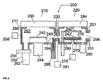
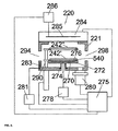
ここで図2を参照すると、基材の化学処理および熱処理を実施するためのプロセッシングシステム200が示されている。プロセッシングシステム200は、第1の化学処理システム210と、第1の化学処理システム210に連結された第2の熱処理システム220とを備えている。化学処理システム210は温度制御可能な化学処理チャンバ211を備えている。熱処理システム220は温度制御可能な熱処理チャンバ221を備えている。詳細は以下に記載するが、化学処理チャンバ211および熱処理チャンバ221は、断熱アセンブリ230を使用して互いに断熱可能であり、また、ゲートバルブアセンブリ296を使用して互いに真空分離可能である。
Referring now to FIG. 2, a
図2および図3に示されるように、化学処理システム210は、化学処理チャンバ211から実質的に熱的に分離されるように構成され、かつ基材242を支持するように構成された温度制御される基材ホルダ240と、化学処理チャンバ211を排気するように化学処理チャンバ211に連結された真空排気システム250と、化学処理チャンバ211内のプロセス空間262にプロセスガスを導入するためのガス供給システム260とをさらに備えている。
As shown in FIGS. 2 and 3, the
図2および図5に示されるように、熱処理システム220は、熱処理チャンバ221内に取り付けられ、熱処理チャンバ221から実質的に熱的に絶縁されるように構成されて、かつ基材242’を支持するように構成された温度制御される基材ホルダ270と、熱処理チャンバ221を排気する真空排気システム280と、熱処理チャンバ221に連結された基材リフタアセンブリ290とをさらに備えている。リフタアセンブリ290は、保持平面(実線)と基材ホルダ270(破線)の間で、またはその間に位置する移送平面へ、基材242’’を垂直に移動させることができる。熱処理チャンバ221は上部アセンブリ284をさらに備えることができる
As shown in FIGS. 2 and 5, the
また、化学処理チャンバ211、熱処理チャンバ221および断熱アセンブリ230は、基材が通り抜けることができる共通の開口部294を画定する。2つのチャンバ211,221内で別個の処理を行なえるよう、処理中、ゲートバルブアセンブリ296を用いて共通の開口部294を密封できる。また、図1Aに示されるように移送システムで基材交換できるようにするために、移送開口部298を熱処理チャンバ221に形成できる。例えば、移送システム(図示せず)から熱処理チャンバ221を断熱するために第2の断熱アセンブリ231を組み込むことができる。開口部298は(図1Aに合わせて)熱処理チャンバ221の一部として示されているが、移送開口部298は、熱処理チャンバ221ではなく化学処理チャンバ211に形成することもできるし(図1Aで示されるのと逆のチャンバ位置)、化学処理チャンバ211と熱処理チャンバ221の両方に(図1Bおよび図1Cに示されるように)に形成することもできる。
Also, the
図2および図3に示されるように、化学処理システム210は、基材242を熱制御して処理するためのいくつかの操作上の機能を提供するために、基材ホルダ240および基材ホルダアセンブリ244を備えている。基材ホルダ240および基材ホルダアセンブリ244は、基材242を基材ホルダ240に電気的に(または機械的に)クランプするために、静電クランピングシステム(または機械的クランピングシステム)を備えることができる。また、基材ホルダ240は、例えば、基材ホルダ240から熱を受けとって、熱交換器システム(図示せず)へ熱を伝達するか、または加熱時に熱交換器システムの熱を伝達する、循環する冷却剤流を有する冷却システムをさらに含むことができる。また、例えば、基材242と基材ホルダ240間のガス空隙(gas−gap)熱伝導係数を改善するように裏面ガスシステムを介して基材242の裏面に伝熱ガスを供給することも可能である。例えば、基材242の裏面に供給される伝熱ガスは、ヘリウム、アルゴン、キセノン、クリプトンなどの不活性ガス、プロセスガス、または酸素、窒素もしくは水素などの他のガスを含むことができる。このようなシステムは、温度の上昇または下降時に基材の温度制御が必要な場合に利用できる。例えば、裏面ガスシステムは、裏面ガス空隙圧力を基材242の中心部および縁部の間で別々に変化させることが可能な2ゾーン(中心部と縁部)システムなど、マルチゾーンガス供給システムを有することができる。他の実施形態において、例えば抵抗加熱素子などの加熱用/冷却用素子または熱電ヒータ/クーラを化学処理チャンバ211のチャンバ壁とともに基材ホルダ240内に含むことができる。
As shown in FIGS. 2 and 3, the
例えば、図7は上述の機能のうちのいくつかを実行するために温度制御される基材ホルダ300を示す。基材ホルダ300は、化学処理チャンバ211の下壁に連結されるチャンバ嵌合部品310、チャンバ嵌合部品310に連結される断熱部品312、および断熱部品312に連結される温度制御部品314を備えている。チャンバ嵌合部品310および温度制御部品314は、例えば、電気的および熱的に伝導する材料、例えばアルミニウム、ステンレス鋼、ニッケルなどから製造できる。断熱部品312は、例えば、石英、アルミナ、テフロン(登録商標)など熱伝導率が比較的低い耐熱材料から製造できる。
For example, FIG. 7 shows a
温度制御部品314は、冷却チャネル、加熱チャネル、抵抗加熱素子または熱電素子などの温度制御素子を備えることができる。例えば、図7に示されているように、温度制御部品314は、クーラント入口322とクーラント出口324を有するクーラントチャネルを備える。クーラントチャネル320は、例えば、温度制御部品314を対流式に伝導冷却するために、水、Fluorinert、Galden HT−135等のクーラントを特定流量流せる、温度制御部品314内の螺旋状の通路とすることができる。あるいは、温度制御部品314は、それぞれの素子を通る電気的な電流の流れの方向によって、基材を加熱または冷却することができる熱電変換素子のアレイを含むことができる。代表的な熱電変換素子として、Advanced Thermoelectricから市販されているもので、Model ST−127−1.4−8.5M(最大可能伝熱性能72Wの40mm×40mm×3.4mmの熱電デバイス)がある。
The temperature control component 314 can include a temperature control element such as a cooling channel, a heating channel, a resistance heating element, or a thermoelectric element. For example, as shown in FIG. 7, the temperature control component 314 includes a coolant channel having a
また、基材ホルダ300は、静電クランプ(ESC)328をさらに備えることができる。静電クランプ328は、セラミック層330と、その中に埋設されたクランピング電極332と、電気的接続336を使用してクランピング電極332に接続された高電圧(HV)直流電圧源334とを含んでいる。ESC328は、例えば、単極式とすることもできるし、双極式とすることもできる。このようなクランプの設計および実装は、静電クランピングシステムの当業者にとって周知である。
In addition, the
また、基材ホルダ300は、少なくとも1つのガス供給ライン342を介して基材242の裏面に、例えばヘリウム、アルゴン、キセノン、クリプトンを含む不活性ガス、プロセスガス、または酸素、窒素もしくは水素を含む他のガスをはじめとする伝熱ガスを供給するための裏面ガス供給システム340と、複数のオリフィスおよび複数のチャネルのうちの少なくとも一方とをさらに備えることができる。裏面ガス供給システム340は、例えば、裏面圧力が中心部から縁部に向かって放射状に変化し得る2ゾーン(中心部と縁部)システムなどのマルチゾーン供給システムとすることができる。
In addition, the
断熱部品312は、温度制御部品314と下層の嵌合部品310との間の断熱を強化するために断熱用空隙350をさらに含むことができる。断熱用空隙350は、排気システム(図示せず)、または真空排気システム250の一部としての真空ラインを使用して排気でき、および/または、その熱伝導率を変えるためにガス供給(図示せず)に接続できる。ガス供給は、例えば、伝熱ガスを基材242の裏面に接続するために利用される裏面ガス供給340とすることができる。
The
嵌合部品310は、基材ホルダ300の上面および処理システムの移送面へ/から基材242を垂直に移動するために、3つまたはそれより多いリフトピン362を上下させることができるリフトピンアセンブリ360をさらに含むことができる。
The
各部品310、312および314は、1つの部品を他の部品に固着し、基材ホルダ300を化学処理チャンバ211に固着するために、(ボルトおよびねじ穴などの)固定用デバイスをさらに備えている。また、各部品310、312および314は、それぞれの部品への上記ユーティリティの通過を容易にするものであり、また、プロセッシングシステムの真空完全性を維持するために必要があれば、エラストマのO−リングなどの真空シールが利用される。
Each
温度制御される基材ホルダ240の温度は、熱電対(例えばKタイプ熱電対、Ptセンサ等)などの感温デバイス344を使用して監視可能である。また、コントローラは、基材ホルダ240の温度を制御するために、基材ホルダアセンブリ244へのフィードバックとして温度測定を利用できる。例えば、基材ホルダ240および/または基材242の温度変化に影響を与えるために、流体流速、流体温度、伝熱ガスタイプ、伝熱ガス圧、クランプ力、抵抗ヒータ素子の電流または電圧、および熱電デバイスの電流または極性等の少なくとも1つを調整できる。
The temperature of the
図2および図3を再び参照すると、化学処理システム210はガス供給システム260を備えている。一実施形態において、図8に示されるように、ガス供給システム400は、ガス供給アセンブリ402を有するシャワーヘッドガス注入システムと、ガス供給アセンブリ402に連結され、ガス供給プレナム406を形成するように構成されたガス供給プレート404とを備えている。図示されていないが、ガス供給プレナム406は、1つまたはそれより多いガス供給バッフルプレートを備えることができる。ガス供給プレート404は、化学処理チャンバ211内でガス供給プレナム406からプロセス空間までプロセスガスを供給するための1つまたはそれより多いガス供給オリフィス408をさらに備えている。また、1種類以上のガスを含むプロセスガスを供給するために、1つまたはそれより多いガス供給ライン410,410’等を、例えばガス供給アセンブリを介してガス供給プレナム406に接続することができる。プロセスガスは、例えば、NH3、HF、H2、O2、CO,CO2、Ar、He等を含むことができる。
Referring back to FIGS. 2 and 3, the
別の実施形態では、図9Aおよび図9B(図9Aの拡大図)に示されるように、少なくとも2種類のガスを含むプロセスガスを供給するためのガス供給システム420が、1つまたはそれ以上の部品424、426および428を有するガス供給アセンブリ422と、ガス供給アセンブリ422に接続され、第1のガスを化学処理チャンバ211のプロセス空間に接続する構成された第1のガス供給プレート430と、第1のガス供給プレート430に接続され、第2のガスを化学処理チャンバ211のプロセス空間に接続させるように構成された第2のガス供給プレート432とを備えている。ガス供給アセンブリ422に接続されるときに、第1のガス供給プレート430は第1のガス供給プレナム440を形成する。また、第1のガス供給プレート430に接続されるときに、第2のガス供給プレート432は第2のガス供給プレナム442を形成する。図示されていないが、ガス供給プレナム440、442は、1つまたはそれより多いガス供給バッフルプレートを備えることができる。第2のガス供給プレート432は、第1のガス供給プレート430内に形成された1つまたはそれより多い通路446のアレイに接続され一致する1つまたはそれより多いオリフィスの第1のアレイ444と、1つまたはそれより多いオリフィスの第2のアレイ448とを、さらに備えている。1つまたはそれより多いオリフィスの第1のアレイ444は、1つまたはそれより多い通路のアレイ446と合わさって、第1のガス供給プレナム440から化学処理チャンバ211のプロセス空間へ第1のガスを供給するように構成されている。1つまたはそれより多いオリフィスの第2の配列448は、第2のガス供給プレナム442から化学処理チャンバ211のプロセス空間へ第2のガスを供給するように構成されている。プロセスガスは、例えば、NH3、HF、H2、O2、CO,CO2、Ar、He等を含むことができる。この構成の結果、第1のガスおよび第2のガスは、プロセス空間内を除き、いかなる相互作用も無く別々にプロセス空間に導入される。
In another embodiment, as shown in FIGS. 9A and 9B (enlarged view of FIG. 9A), a
図10Aに示されるように、第1のガスは、ガス供給アセンブリ422内に形成された第1のガス供給通路450を介して、第1のガス供給プレナム440に接続できる。また、図10Bに示されるように、第2のガスは、ガス供給アセンブリ422内に形成された第2のガス供給通路452を介して、第2のガス供給プレナム442に接続できる。
As shown in FIG. 10A, the first gas may be connected to the first
再び図2および図3を参照すると、化学処理システム220は、昇温状態に維持される温度制御される化学処理チャンバ211をさらに備えている。例えば、壁加熱素子266を壁温度制御ユニット268に接続することができ、この壁加熱素子266は化学処理チャンバ211に接続するように構成できる。加熱素子は、例えば、タングステン、ニッケル−クロム合金、アルミニウム−鉄合金、窒化アルミニウム、その他のフィラメントなどの抵抗ヒータ素子を含むことができる。抵抗加熱素子を製作するための市販の材料の例として、Kanthal、Nikrothal、Akrothalなどがある。これらはいずれもコネチカット州ベセルのKanthal Corporationによって製造された合金の登録商標名である。Kanthal系はフェライト合金(FeCrAl)を含み、Nikrothal系はオーステナイト合金(NiCr、NiCrFe)を含む。電流がフィラメントを通るときに電力が熱として放散されるので、壁温度制御ユニット268は、例えば、制御可能な直流電源を備えることができる。例えば、壁加熱素子266は、Watlow(60510、イリノイ州、バタビア、キングズランドドクタ1310)から市販されているFirerodカートリッジヒータを少なくとも1つ備えることができる。化学処理チャンバ211に冷却素子を使用することもできる。化学処理システム211の温度は、熱電対(例えばKタイプ熱電対、Ptセンサ等)などの感温デバイスを使用して監視可能である。また、コントローラは、化学処理チャンバ211の温度を制御するために、壁温度制御ユニット268へのフィードバックとして温度測定を利用できる。
Referring again to FIGS. 2 and 3, the
再び図3を参照すると、化学処理システム210は、任意の指定温度に維持可能な、温度制御されるガス供給システム260をさらに備えることができる。例えば、ガス供給加熱素子267をガス供給システム温度制御ユニット269に接続することができ、このガス供給加熱素子267はガス供給システム260に接続するように構成できる。加熱素子は、例えば、タングステン、ニッケル−クロム合金、アルミニウム−鉄合金、窒化アルミニウム、その他のフィラメントなどの抵抗ヒータ素子を含むことができる。抵抗加熱素子を製作するための市販の材料の例として、Kanthal、Nikrothal、Akrothalなどがある。これらはいずれもコネチカット州ベセルのKanthal Corporationによって製造された合金の登録商標名である。Kanthal系はフェライト合金(FeCrAl)を含み、Nikrothal系はオーステナイト合金(NiCr、NiCrFe)を含む。電流がフィラメントを通るときに電力が熱として放散されるので、ガス供給システム温度制御ユニット269は、例えば、制御可能な直流電源を備えることができる。例えば、ガス供給加熱素子267は、約1400W(または約5W/in2の出力密度)を許容できる2領域シリコーンゴムヒータ(厚さ約1.0mm)を備えることができる。ガス供給システム260の温度は、熱電対(例えばKタイプ熱電対、Ptセンサ等)などの感温デバイスを使用して監視可能である。また、コントローラは、ガス供給システム260の温度を制御するために、ガス供給システム温度制御ユニット269へのフィードバックとして温度測定を利用できる。図8〜図10Bのガス供給システムは温度制御システムを内蔵することもできる。あるいは、または、それに加え、いずれの実施形態にも冷却素子を使用できる。
Referring again to FIG. 3, the
図2および3をさらに参照すると、真空排気システム250は、真空ポンプ252と、チャンバ圧をスロットル調整するためのゲートバルブ254とを含むことができる。真空ポンプ252は、例えば、毎秒約5000リットル(以上)までの排気スピードが可能なターボ分子ポンプ(TMP)を備えることができる。例えば、TMPは、セイコーSTP−A803真空ポンプまたは荏原ET1301W真空ポンプとすることができる。TMPは一般に約50mTorr未満の低圧プロセスに有用である。高圧(すなわち、約100mTorrより高い)または低スループットプロセス(すなわち気体流なし)の場合、メカニカルブースターポンプおよびドライ粗引きポンプを使用できる。
With further reference to FIGS. 2 and 3, the
図3を再度参照し、化学処理システム210は、マイクロプロセッサと、メモリと、デジタルl/Oポートとを有するコントローラ235をさらに備えることができ、デジタルl/Oポートは、化学処理システム210への入力と通信してこれを起動し、温度および圧力感知装置などの化学処理システム210からの出力を監視するのに十分な制御電圧を生成できる。また、コントローラ235は、基材ホルダアセンブリ244、ガス供給システム260、真空排気システム250、ゲートバルブアセンブリ296、壁温度制御ユニット268およびガス供給システム温度制御ユニット269に接続され、これらと情報交換できる。プロセスレシピに従って化学処理システム210の上述部品への入力を起動させるために、例えば、メモリに格納されたプログラムを利用できる。コントローラ235の一例は、テキサス州オースチンのDell Corporationから入手可能なDell Precision Workstation 610(商標)である。
Referring back to FIG. 3, the
一例として、図4は、把手213と少なくとも1つの留め金214と少なくとも1つのヒンジ217とを備える蓋212、光学ビューポート215、および少なくとも1つの圧力感知装置216とをさらに有する化学処理システム210’を示す。
As an example, FIG. 4 shows a
図2および図5に記載されているように、熱処理システム220は、温度制御される基材ホルダ270をさらに備えている。基材ホルダ270は、熱障壁274を使用して熱処理チャンバ221から断熱された台座272を備えている。例えば、基材ホルダ270は、アルミニウム、ステンレス鋼またはニッケルから製作でき、熱障壁274は、テフロン(登録商標)、アルミナまたは石英などの断熱材から製作できる。基材ホルダ270は、その内部に埋設される加熱素子276、および基材ホルダに接続される基材ホルダ温度制御ユニット278をさらに備えている。加熱素子は、例えば、タングステン、ニッケル−クロム合金、アルミニウム−鉄合金、窒化アルミニウム、その他のフィラメントなどの抵抗ヒータ素子を含むことができる。抵抗加熱素子を製作するための市販の材料の例として、Kanthal、Nikrothal、Akrothalなどがある。これらはいずれもコネチカット州ベセルのKanthal Corporationによって製造された合金の登録商標名である。Kanthal系はフェライト合金(FeCrAl)を含み、Nikrothal系はオーステナイト合金(NiCr、NiCrFe)を含む。電流がフィラメントを通るときに電力が熱として放散されるので、基材ホルダ温度制御ユニット278は、例えば、制御可能な直流電源を備えることができる。あるいは、温度制御される基材ホルダ270は、例えば、400〜450℃の最高動作温度が可能であるWatlow(60510、イリノイ州、バタビア、キングズランドドクタ1310)から市販されている鋳込みヒータ、または、やはりWatlowから市販され、約300℃程度の動作温度と、約23W/cm2までの出力密度が可能な窒化アルミニウム材料を含むフィルムヒーターとすることができる。あるいは、基材ホルダ270に冷却素子を内蔵することができる。
As described in FIGS. 2 and 5, the
基材ホルダ270の温度は、熱電対(例えばKタイプ熱電対、Ptセンサ等)などの感温デバイスを使用して監視可能である。また、コントローラは、基材ホルダ270の温度を制御するために、基材ホルダ温度制御ユニット278へのフィードバックとして温度測定を利用できる。
The temperature of the
また、例えば約50℃〜2000℃の測定および約±1.5℃の精度を提供できるAdvanced Energies, Inc(80525コネチカット州フォートコリンズ、シャープポイントドライブ1625)から市販されている光ファイバー温度計モデルNo.OR2000F、またはその内容全体を文献参照によって本願明細書に組み込んだものとする2002年7月2日に出願された係属中の米国特許出願10/168544に記載のバンドエッジ温度計測システムをはじめとする感温デバイスを使用して基材の温度を監視できる。
Also, for example, an optical fiber thermometer model No. commercially available from Advanced Energy, Inc. (Sharp Point Drive 1625, Fort Collins, 80525) that can provide measurements of about 50 ° C. to 2000 ° C. and accuracy of about ± 1.5 ° C. OR2000F, or the band edge temperature measurement system described in pending
再び図5を参照すると、熱処理システム220は、指定温度に維持される、温度制御される熱処理チャンバ221をさらに備えている。例えば、熱壁加熱素子283を熱壁温度制御ユニット281に接続することができ、この熱壁加熱素子283は壁処理チャンバ221に接続するように構成できる。加熱素子は、例えば、タングステン、ニッケル−クロム合金、アルミニウム−鉄合金、窒化アルミニウム、その他、フィラメントなどの抵抗ヒータ素子を含むことができる。抵抗加熱素子を製作するための市販の材料の例として、Kanthal、Nikrothal、Akrothalなどがある。これらはいずれもコネチカット州ベセルのKanthal Corporationによって製造された合金の登録商標名である。Kanthal系はフェライト合金(FeCrAl)を含み、Nikrothal系はオーステナイト合金(NiCr、NiCrFe)を含む。電流がフィラメントを通るときに電力が熱として放散されるので、熱壁温度制御ユニット281は、例えば、制御可能な直流電源を備えることができる。例えば、熱壁加熱素子283は、Watlow(60510、イリノイ州、バタビア、キングズランドドクタ1310)から市販されているFirerodカートリッジヒータを少なくとも1つ備えることができる。あるいは、または、それに加え、熱処理チャンバ221に冷却素子を使用できる。熱処理システム221の温度は、熱電対(例えばKタイプ熱電対、Ptセンサ等)などの感温デバイスを使用して監視可能である。また、コントローラは、熱処理チャンバ221の温度を制御するために、熱壁温度制御ユニット281へのフィードバックとして温度測定を利用できる。
Referring again to FIG. 5, the
図2および図5をさらに参照すると、熱処理システム220は上部アセンブリ284をさらに備えている。上部アセンブリ284は、例えば、パージガス、プロセスガスまたはクリーニングガスを熱処理チャンバ221に導入するためのガス注入システムを含むことができる。あるいは、熱処理チャンバ221は、上部アセンブリとは別個のガス注入システムを備えることができる。例えば、パージガス、プロセスガスまたはクリーニングガスは、熱処理チャンバの側壁から熱処理チャンバ221に導入できる。熱処理チャンバは、少なくとも1つのヒンジと、把手と、閉位置の蓋に掛け金をかけるための留め金とを有するカバーまたは蓋をさらに備えることができる。別の実施形態において、上部アセンブリ284は、基材リフタアセンブリ290のブレード500(図11を参照)の上に載っている基材242’’を加熱するためのタングステンハロゲンランプのアレイなどの放射ヒータを備えることができる。この場合、基材ホルダ270を熱処理チャンバ221から除外することもできる。
With further reference to FIGS. 2 and 5, the
再び図5を参照すると、熱処理システム220は、指定温度に維持可能な温度制御される上部アセンブリ284をさらに備えている。例えば、上側アセンブリ加熱素子285を上側アセンブリ温度制御ユニット286に接続することができ、この上側アセンブリ加熱素子285は上側アセンブリ284に接続するように構成できる。加熱素子は、例えば、タングステン、ニッケル−クロム合金、アルミニウム−鉄合金、窒化アルミニウム、その他のフィラメントなどの抵抗ヒータ素子を含むことができる。抵抗加熱素子を製作するための市販の材料の例として、Kanthal、Nikrothal、Akrothalなどがある。これらはいずれもコネチカット州ベセルのKanthal Corporationによって製造された合金の登録商標名である。Kanthal系はフェライト合金(FeCrAl)を含み、Nikrothal系はオーステナイト合金(NiCr、NiCrFe)を含む。電流がフィラメントを通るときに電力が熱として放散されるので、上側アセンブリ温度制御ユニット286は、例えば、制御可能な直流電源を備えることができる。例えば、上側アセンブリ加熱素子285は、約1400W(または約5W/in2の出力密度)を許容できる2領域シリコーンゴムヒータ(厚さ約1.0mm)を備えることができる。上側アセンブリ284の温度は、熱電対(例えば、Kタイプ熱電対、Ptセンサ等)などの感温デバイスを使用して監視可能である。また、コントローラは、上側アセンブリ284の温度を制御するために、上側アセンブリ温度制御ユニット286へのフィードバックとして温度測定を利用できる。あるいは、または、それに加え、上側アセンブリ284に冷却素子を含むこともできる。
Referring again to FIG. 5, the
再び図2および図5を参照すると、熱処理システム220は基材リフタアセンブリ290をさらに備えている。基材リフタアセンブリ290は、基材ホルダ270の上側表面に基材242’を下降させ、また、基材ホルダ270の上側表面から保持平面、またはその間の移送平面に基材242’’を上昇させように構成される。移送平面では、化学処理チャンバ211および熱処理221との間で基材を移送するために利用される移送システムを用いて基材242’’を交換できる。保持平面では、他の基材が移送システムおよび化学処理チャンバ211または熱処理チャンバ221とのの間で交換される間に、基材242’’を冷却できる。図11に示すように、基材リフタアセンブリ290は、3つまたはそれより多いタブ510を有するブレード500と、基材リフタアセンブリ290を熱処理チャンバ221に接続させるためのフランジ520と、熱処理チャンバ221内でブレード500の垂直移動を可能にする駆動システム530とを備える。タブ510は、上昇位置において基材242’’を把持し、下降位置のときには、基材ホルダ270内に形成された収容キャビティ540内に引っ込むように構成される(図5参照)。駆動システム530は、例えば、シリンダー行程長、シリンダー行程速度、位置精度、非回転精度等を含むさまざまな仕様を満足するように設計された空圧駆動システムとすることができ、その設計は、空圧駆動システム設計の当業者に公知である。
Referring again to FIGS. 2 and 5, the
再び図2および図5を参照すると、熱処理システム220は真空排気システム280をさらに備えている。真空排気システム280は、例えば、真空ポンプおよび、ゲートバルブまたはバタフライバルブなどのスロットルバルブを含むことができる。真空ポンプは、例えば、毎秒約5000リットル(以上)までの排気スピードが可能なターボ分子真空ポンプ(TMP)を備えることができる。TMPは一般に約50mTorr未満の低圧プロセスに有用である。高圧プロセス(すなわち、約100mTorrより高い)の場合、メカニカルブースターポンプおよびドライ粗引きポンプを使用できる。
Referring back to FIGS. 2 and 5, the
図5を再度参照すると、熱処理システム220は、マイクロプロセッサと、メモリと、デジタルl/Oポートとを有するコントローラ275をさらに備えることができ、デジタルl/Oポートは、熱処理システム220への入力と通信してこれを起動し、熱処理システム220からの出力を監視するのに十分な制御電圧を生成できる。また、コントローラ275は、基材ホルダ温度制御ユニット278、上部アセンブリ温度制御ユニット286、上部アセンブリ284、熱壁温度制御ユニット281、真空排気システム280および基材リフタアセンブリ290に接続され、これらと情報を交換することができる。例えば、プロセスレシピに従って熱処理システム220の上述部品への入力を起動させるために、例えば、メモリに格納されたプログラムを利用できる。コントローラ275の一例は、テキサス州オースチンのDell Corporationから入手可能なDell Precision Workstation 610(商標)である。
Referring back to FIG. 5, the
別の実施形態において、コントローラ235および275は同じコントローラとすることができる。
In another embodiment, the
一例として、図6は、把手223と少なくとも1つのヒンジ224とを備える蓋222、光学ビューポート225、および少なくとも1つの圧力感知装置226をさらに有する熱処理システム220’を示す。また、熱処理システム220’は、基材が保持平面にあるかどうか識別するために、基材検出システム227をさらに備えている。基材検出システムは、例えば、キーエンスデジタルレーザセンサを備えることができる。
As an example, FIG. 6 shows a
図12、13および14は、断熱アセンブリ230の側面図、平面図および側断面図をそれぞれ示す。断熱アセンブリ50、150または650のような類似したアセンブリを使用することも可能である。断熱アセンブリ230は、例えば、図12に示されるように、化学処理チャンバ211に接続され、かつ熱処理チャンバ221(図14を参照)と化学処理チャンバ211との間に構造的な接触部を形成するように構成されたインタフェースプレート231と、このインタフェースプレート231に接続され、熱処理チャンバ221と化学処理チャンバ211との間の熱接触を減らすように構成された断熱プレート232とを備えることができる。さらにまた、図12において、インタフェースプレート231は、熱処理チャンバ221上の合わせ面に接続するように構成された合わせ面234、を有する1つまたはそれより多い構造的接触部材233を備えている。インタフェースプレート231は、2つのチャンバ211、221間にしっかりした接触部を形成するために、アルミニウム、ステンレス鋼等の金属から製作できる。断熱プレート232は、例えば、テフロン(登録商標)、アルミナ、石英など、熱伝導率が比較的低い材料から製作できる。断熱アセンブリについては、「隣接した温度制御されるチャンバを熱的に絶縁するための方法と装置(Method and Apparatus for Thermally Insulating Adjacent Temperature Controlled Chambers)」という名称の2003年11月12日に出願された係属中の米国特許出願第10/705,397号に詳細に記載されており、その内容全体を文献参照によってここに組み込んだものとする。
12, 13 and 14 show a side view, a plan view and a side cross-sectional view of the
図2および図14にて示されるように、ゲートバルブアセンブリ297は、共通開口部294を開閉するためにゲートバルブ297を垂直移動するように利用される。ゲートバルブアセンブリ296は、真空シールにインタフェースプレート231を提供し、かつシールにゲートバルブ297を提供するゲートバルブアダプタプレート239をさらに備えることができる。
As shown in FIGS. 2 and 14, the
2つのチャンバ211、221は、図6のように、1つまたはそれより多いアラインメントデバイス235を使用し、1つまたはそれより多いアライメントレセプタ235’で終端するように互いに接続することができ、また、第1のチャンバ(例えば化学処理チャンバ211)上のフランジ237を貫通し、第2のチャンバ(例えば熱処理チャンバ221)の1つまたはそれより多い受け入れデバイス236’(すなわちタップ穴)内で図6のように終端する1つまたはそれより多い固定デバイス236(すなわちボルト)と接続することができる。図14に示すように、真空シールは、例えば、エラストマのOリングシール238を使用して、断熱プレート232、インタフェースプレート231、ゲートアダプタプレート239、および化学処理チャンバ211の間に形成でき、真空シールは、Oリングシール238を介して、インタフェースプレート232と熱処理チャンバ221の間に形成できる。
The two
また、化学処理チャンバ211および熱処理チャンバ221を備える部品の1つまたはそれより多い表面を防護壁で被覆できる。防護壁は、カプトン、テフロン(登録商標)、表面陽極酸化、アルミナやイットリア等のセラミックスプレー塗装、プラズマ電解酸化等のうちの少なくとも1つを含むことができる。
Also, one or more surfaces of the parts comprising the
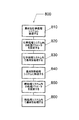
図15は、化学処理システム210および熱処理システム220を備えているプロセッシングシステム200を操作する方法を示す。この方法は、ステップ810から始まるフローチャート800として示され、ここで基材は、基材移送システムを使用して化学処理システム210に移送される。基材は、基材ホルダ内に収容されるリフトピンによって受け取られ、基材ホルダに降ろされる。その後、基材は静電クランピングシステムなどのクランピングシステムを使用して基材ホルダに固定され、基材の裏面に伝熱ガスが供給される。
FIG. 15 illustrates a method of operating a
ステップ820において、基材の化学処理のための1つまたはそれより多い化学処理パラメータが設定される。例えば、1つまたはそれより多い化学処理パラメータは、化学処理プロセス圧力、化学処理壁温度、化学処理基材ホルダ温度、化学処理基材温度、化学処理ガス供給システム温度、および化学処理ガス流量のうちの少なくとも1つを含む。例えば、次のうちの1つ以上が起こり得る:1)壁温度制御ユニットおよび第1の感温デバイスに接続されたコントローラが、化学処理チャンバの化学処理チャンバ温度を設定するために利用される、2)ガス供給システム温度制御ユニットおよび第2の感温デバイスに接続されたコントローラが、化学処理チャンバの化学処理ガス供給システム温度を設定するために利用される;3)少なくとも1つの温度制御素子および第3の感温デバイスに接続されたコントローラが、化学処理基材ホルダ温度をセットするために利用される;4)温度制御素子、裏面ガス供給システム、クランピングシステム、および基材ホルダ内の第4の感温デバイスのうちの少なくとも1つに接続されたコントローラが、化学処理基材温度を設定するために利用される;5)真空排気システム、ガス供給システムおよび圧力感知装置のうちの少なくとも1つに接続されたコントローラが、化学処理チャンバ内のプロセス圧力を設定するために利用される;および/または、6)1つまたはそれより多いプロセスガスの質量流量が、ガス供給システム内の1つまたはそれより多い質量流量コントローラに接続されたコントローラによって設定される。
In
ステップ830において、基材は、第1の期間のあいだ、ステップ820に記載される条件下で化学処理される。第1の期間は、例えば約10〜約480秒の範囲とすることができる。
In
ステップ840において、基材は、化学処理チャンバから熱処理チャンバへ移送される。その時間中に基材クランプが外され、基材の裏面への伝熱ガスの流れは終了される。基材は、基材ホルダ内に収容されているリフトピンアセンブリを用いて、基材ホルダから移送平面へ垂直に持ち上げられる。移送システムはリフトピンから基材を受けとり、基材を熱処理システム内に配置する。その中で、基材リフタアセンブリが移送システムから基材を受けとり、基材を基材ホルダへ降ろす。
In
ステップ850において、基材の熱処理のための熱処理パラメータが設定される。例えば、1つまたはそれより多い熱処理パラメータは、熱処理壁温度、熱処理上部アセンブリ温度、熱処理基材温度、熱処理基材ホルダ温度、熱処理基材温度、および熱処理プロセス圧力のうちの少なくとも1つを含む。例えば、次のうちの1つ以上が起こり得る:1)熱壁温度制御ユニットおよび熱処理チャンバの第1の感温デバイスに接続されたコントローラが、熱処理壁温度を設定するために利用される、2)上部アセンブリ温度制御ユニットおよび上部アセンブリの第2の感温デバイスに接続されたコントローラが、熱処理上部アセンブリ温度を設定するために利用される、3)基材ホルダ温度制御ユニットおよび加熱された基材ホルダの第3の感温デバイスに接続されたコントローラが、熱処理基材ホルダ温度を設定するために利用される、4)基材ホルダ温度制御ユニットおよび加熱された基材ホルダの第4の感温デバイスに接続され、基材に接続されたコントローラが、熱処理基材温度を設定するために利用される、および/または、5)真空排気システム、ガス供給システム、および圧力感知装置に接続されたコントローラが、熱処理チャンバ内の熱処理プロセス圧力を設定するために利用される。
In
ステップ860において、基材は、第2の期間のあいだ、ステップ850に記載される条件下で熱処理される。第2の期間は、例えば約10〜約480秒の範囲とすることができる。
In
一例として、プロセッシングシステム200は、図2に示されるように、酸化物ハードマスクをトリミングするための化学的酸化物除去システムとすることができる。プロセッシングシステム200は、酸化物表面層など、基材上の露出面層を化学処理する化学処理システム210を備え、それによって露出面上のプロセス化学物質(process
chemistry)の吸着が表面層の化学変換に影響を及ぼす。また、プロセッシングシステム200は基材を熱処理する熱処理システム220を備え、それによって、基材上の化学変更された露出面層を脱離(または蒸発)させるために基材温度が昇温される。
As an example, the
chemistry) affects the chemical transformation of the surface layer. The
化学処理システム210において、プロセス空間262(図2を参照)が真空排気され、HFなどの第1のプロセスガスおよびNH3などの第2のプロセスガスを含むプロセスガスが導入される。あるいは、第1および第2のプロセスガスは、キャリヤガスをさらに含むことができる。キャリヤガスは、例えば、アルゴン、キセノン、ヘリウム等の不活性ガスを含むことができる。プロセス圧力は、約1〜約100mTorrまでの範囲とすることができ、例えば、約2〜約25mTorrまでの範囲とすることができる。プロセスガスの流量は、各種について、約1〜約200sccmまでの範囲とすることができ、例えば、約10〜約100sccmまでの範囲とすることができる。
In
また、化学処理チャンバ211は、約10℃〜約200℃の範囲の温度に加熱でき、例えば、約35℃〜約55℃の範囲とすることができる。また、ガス供給システムは、約10℃〜約200℃の範囲の温度に加熱でき、例えば、約40℃〜約60℃の範囲とすることができる。また、基材は、約10℃〜約50℃の範囲の温度に維持することができ、例えば、基材の温度を約25℃〜約30℃の範囲とすることができる。
Also, the
また、熱処理システム220において、熱処理チャンバ221は、約20℃〜約200℃の範囲の温度に加熱でき、例えば、約75℃〜約100℃の範囲とすることができる。また、上部アセンブリは、約20℃〜約200℃の範囲の温度に加熱でき、例えば、約75℃〜約100℃の範囲とすることができる。また、基材は、上部アセンブリは、約100〜約200℃の範囲で約100℃を超える温度に加熱することができ、例えば、約100〜約150℃の範囲とすることができる。
Further, in the
上述のように、化学処理システム210で利用される第1および第2のプロセスガスはHFおよびNH3を含むことができる。図9A、9B、10Aおよび10Bに示されるガス供給システムを使用する場合、第1のプロセスガスHFが、第2のプロセスガスNH3とは別個の化学処理システム内のプロセス空間に導入される。あるいは、この2種類のプロセスガスが混合されて、ガスの混合物としてプロセス空間に導入される。
As described above, the first and second process gases utilized in the
図16は、プロセス圧力15mTorrの場合の(モル)HFガス比(すなわちHFモル分率)、すなわちプロセスガスの総モル数に対するHFモル数の比、の関数としてトリミング量データ(nm;アスタリスク「*」で表されている)を示す。この間、基材は第1のプロセスガス(HF)と第2のプロセスガス(NH3)にさらされる。プロセスレシピは、例えば、HFの流量、NH3の流量、プロセス空間内の圧力、化学処理システム210内の基材ホルダの温度、および化学処理チャンバ211の温度に対応するものである。例えば、HFガス比がゼロに等しい場合はNH3だけが導入され、HFガス比が1に等しい場合はHFだけが導入される。図16に示されるように、HFガス比50%の場合にトリミング量が最大となる。また、トリミング量データは次の形を有する式(実線)に対応している。
y=A´(1-x) (1)
FIG. 16 shows trimming data (nm; asterisk “*”) as a function of (molar) HF gas ratio (ie, HF mole fraction), ie, the ratio of moles of HF to the total moles of process gas at a process pressure of 15 mTorr. ”). During this time, the substrate is exposed to a first process gas (HF) and a second process gas (NH 3 ). The process recipe corresponds to, for example, the flow rate of HF, the flow rate of NH 3 , the pressure in the process space, the temperature of the substrate holder in the
y = A´ (1-x) (1)
ここで、yはトリミング量を表し、xはHFガス比を表し、Aは定数である。破線は、予測される95%信頼限界を示す。図16に対する上記説明はトリミング量とプロセスガスの(モル)ガス比(すなわち、モル分率)を示すものであるが、この関係式は、トリミング量とプロセスガス(すなわち、第1のプロセスガス、第2のプロセスガス、不活性ガス等)の量との間に確立され得る。例えば、プロセスガスの量は、質量、モル数、質量流量、モル流量、ガス濃度、分圧、質量分率、モル分率、第1のプロセスガスと第2のプロセスガスの間のガス(質量またはモル)比、第1または第2のプロセスガスと不活性ガスとの間のガス(質量またはモル)比、等を含むことができる。 Here, y represents the trimming amount, x represents the HF gas ratio, and A is a constant. The dashed line indicates the predicted 95% confidence limit. The above description for FIG. 16 shows the trimming amount and the (molar) gas ratio of the process gas (that is, the mole fraction), and this relational expression shows the trimming amount and process gas (that is, the first process gas, Second process gas, inert gas, etc.). For example, the amount of process gas may be the mass, number of moles, mass flow rate, molar flow rate, gas concentration, partial pressure, mass fraction, mole fraction, gas between the first process gas and the second process gas (mass Or mole) ratio, gas (mass or mole) ratio between the first or second process gas and the inert gas, and the like.
また、図17は、プロセス圧力約10mTorrの場合の(モル)HFガス比(すなわちHFモル分率)の関数としてトリミング量データ(nm;アスタリスク「*」で表されている)を示す。繰り返すが、トリミング量データは式(1)に示される形の式に対応している。図16および17に示されるトリミング量データの式(1)を使用するということは、トリミング量がHFガス比とNH3ガス比に正比例していることを示唆する。すなわち、次式の通りである。
y=A´(1-x)=Ba(HF)a(NH3) (2)
FIG. 17 also shows trimming amount data (nm; represented by an asterisk “*”) as a function of the (mol) HF gas ratio (ie, HF mole fraction) for a process pressure of about 10 mTorr. Again, the trimming amount data corresponds to an expression of the form shown in expression (1). Using the trimming amount data equation (1) shown in FIGS. 16 and 17 suggests that the trimming amount is directly proportional to the HF gas ratio and the NH 3 gas ratio. That is, it is as follows.
y = A´ (1-x) = Ba (HF) a (NH 3 ) (2)
ここで、α(HF)はモルHFガス比(すなわち、モル分率)を表し、α(NH3)はモルNH3ガス比(すなわち、モル分率)を表し、Bは定数である。あるいは、式(2)は化学プロセスに存在する各種の分圧を含むように書き直すことができる。例えば、次式の通りである。
y=A´(1-x)=BP-2p(HF)p(NH3) (3)
Here, α (HF) represents the molar HF gas ratio (that is, molar fraction), α (NH 3 ) represents the molar NH 3 gas ratio (that is, molar fraction), and B is a constant. Alternatively, equation (2) can be rewritten to include various partial pressures present in the chemical process. For example, it is as follows.
y = A´ (1-x) = BP -2 p (HF) p (NH 3 ) (3)
ここで、p(HF)はHFの分圧を表し、p(NH3)はNH3の分圧を表し、pはプロセス圧力を表し、Bは定数である。各種の分圧は次式で与えられる。
p(HF)={n(HF)/[n(HF)+n(NH3)]}P (4a)
p(NH3)={n(NH3)/[n(HF)+n(NH3)]}P (4b)
または、
p(HF)={(m(HF)/MW(HF))/[m(HF)/MW(HF)+m(NH3)/MW(NH3)]}P (4c)
p(NH3)={(m(NH3)/MW(NH3))/[m(HF)/MW(HF)+m(NH3)/MW(NH3)]}P (4d)
Here, p (HF) represents the partial pressure of HF, p (NH 3 ) represents the partial pressure of NH 3 , p represents the process pressure, and B is a constant. Various partial pressures are given by the following equations.
p (HF) = {n (HF) / [n (HF) + n (NH 3 )]} P (4a)
p (NH 3 ) = {n (NH 3 ) / [n (HF) + n (NH 3 )]} P (4b)
Or
p (HF) = {(m (HF) / MW (HF)) / [m (HF) / MW (HF) + m (NH 3 ) / MW (NH 3 )]} P (4c)
p (NH 3 ) = {(m (NH 3 ) / MW (NH 3 )) / [m (HF) / MW (HF) + m (NH 3 ) / MW (NH 3 )]} P (4d)
ここで、n(HF)はHFのモル数を表し、m(HF)はHFの質量を表し、MW(HF)はHFの分子量を表し、n(NH3)はNH3のモル数を表し、m(NH3)はNH3の質量を表し、MW(NH3)はNH3の分子量を表し、プロセス圧力Pは分圧の合計、すなわち、次式の通りである。
P=p(HF)+p(NH3) (4e)
Here, n (HF) represents the number of moles of HF, m (HF) represents the mass of HF, MW (HF) represents the molecular weight of HF, and n (NH 3 ) represents the number of moles of NH 3. , M (NH 3 ) represents the mass of NH 3 , MW (NH 3 ) represents the molecular weight of NH 3 , and process pressure P is the sum of partial pressures, that is,
P = p (HF) + p (NH 3 ) (4e)
アルゴンなどの不活性ガスも導入されると、(4a〜4d)の式のセットは次の通りとなる。
p(HF)={n(HF)/[n(HF)+n(NH3)+n(Ar)])P (5a)
p(NH3)={n(NH3)/[n(HF)+n(NH3)+n(Ar)]}P (5b)
p(Ar)={n(Ar)/[n(HF)+n(NH3)+n(Ar)]}P (5c)
または、
p(HF)={(m(HF)/MW(HF))/[m(HF)/MW(HF)+m(NH3)/MW(NH3)+m(Ar)/MW(Ar)]}P (5d)
p(NH3)={(m(NH3)/MW(NH3))/[m(HF)/MW(HF)+m(NH3)/MW(NH3)+m(Ar)/MW(Ar)]}P (5e)
p(Ar)={(m(Ar)/MW(Ar))/[m(HF)/MW(HF)+m(NH3)/MW(NH3)+m(Ar)/MW(Ar)]}P (5f)
When an inert gas such as argon is also introduced, the set of equations (4a-4d) is as follows.
p (HF) = (n (HF) / [n (HF) + n (NH 3 ) + n (Ar)]) P (5a)
p (NH 3 ) = {n (NH 3 ) / [n (HF) + n (NH 3 ) + n (Ar)]} P (5b)
p (Ar) = {n (Ar) / [n (HF) + n (NH 3 ) + n (Ar)]} P (5c)
Or
p (HF) = {(m (HF) / MW (HF)) / (m (HF) / MW (HF) + m (NH 3 ) / MW (NH 3 ) + m (Ar) / MW (Ar) ]} P (5d)
p (NH 3 ) = {(m (NH 3 ) / MW (NH 3 )) / (m (HF) / MW (HF) + m (NH 3 ) / MW (NH 3 ) + m (Ar) / MW (Ar)]} P (5e)
p (Ar) = {(m (Ar) / MW (Ar)) / (m (HF) / MW (HF) + m (NH 3 ) / MW (NH 3 ) + m (Ar) / MW (Ar) ]} P (5f)
ここで、n(Ar)はArのモル数を表し、m(Ar)はArの質量を表し、MW(Ar)はArの分子量を表し、プロセス圧力は次式に等しい。
P=p(HF)+p(NH3)+p(Ar) (5g)
Here, n (Ar) represents the number of moles of Ar, m (Ar) represents the mass of Ar, MW (Ar) represents the molecular weight of Ar, and the process pressure is equal to the following formula.
P = p (HF) + p (NH 3 ) + p (Ar) (5g)
上述の式のセットでは、あらゆるところで質量mを対応する質量流量に置換でき、また、あらゆるところでモル数nを対応するモル流量に置換できることに注意されたい。 Note that in the above set of equations, the mass m can be replaced with the corresponding mass flow everywhere, and the number of moles n can be replaced with the corresponding molar flow everywhere.
上で特定された式のセットを使用すると、化学的酸化物除去プロセスにおけるプロセスレシピのパラメータを設定するためのプロセスモデルまたは関係式が得られる。プロセスレシピは、2つまたはそれより多い種の流量とプロセス圧力とを含む。例えば、化学的酸化物除去プロセスのプロセスレシピは、第1の反応種の流量、第2の反応種の流量およびプロセス圧力を含む。あるいは、例えば、プロセスレシピは、第1の反応種の流量、第2の反応種の流量、不活性ガスの流量およびプロセス圧力を含む。前者の例では、第1の反応種の流量をHFの流量とすることができ、第2の反応種の流量をHF3の流量とすることができる。後者の例では、第1の反応種の流量をHFの流量とすることができ、第2の反応種の流量をHF3の流量とすることができ、不活性ガスの流量をArの流量とすることができる。 Using the set of equations identified above, a process model or relationship is obtained for setting process recipe parameters in the chemical oxide removal process. The process recipe includes two or more species flow rates and process pressures. For example, the process recipe for the chemical oxide removal process includes a flow rate of a first reactive species, a flow rate of a second reactive species, and a process pressure. Alternatively, for example, the process recipe includes a flow rate of the first reactive species, a flow rate of the second reactive species, a flow rate of inert gas, and a process pressure. In the former example, the flow rate of the first reactive species can be the flow rate of HF, and the flow rate of the second reactive species can be the flow rate of HF 3 . In the latter example, the flow rate of the first reactive species can be the flow rate of HF, the flow rate of the second reactive species can be the flow rate of HF 3 , and the flow rate of the inert gas can be the flow rate of Ar. can do.
プロセスモデルは、プロセスの結果と変数パラメータとの間の相関を確立するが、少なくとも1つの定数パラメータは一定に保たれる。例えば、プロセス結果は、化学的酸化物除去プロセスにおけるトリミング量を含む。トリミング量と変数パラメータとの関係式は、内挿法、外挿法および/またはデータフィッティングに基づいて決定できる。データフィッティングは、多項式フィッティング、指数関数フィッティングおよび/またはべき乗フィッティング(power law fitting)を含むことができる。プロセスレシピが2つの反応種とプロセス圧力とを含む前者の例では、プロセスモデルの作成中、1つの定数パラメータが一定に保たれる。あるいは、プロセスレシピが2つの反応種と不活性ガスとプロセス圧力とを含む後者の例では、2つの定数パラメータを一定に保つことができる。可変パラメータは、任意のガス種の量(例えば、第1のプロセスガスすなわち反応種の量、第2のプロセスガスすなわち反応種の量、不活性ガスの量、他)とプロセス圧力を含むことができる。例えば、可変パラメータは、任意の種の分圧、任意の種のモル分率、任意の種の質量分率、プロセス圧力、任意の2種類の種の間の質量比、任意の2種類の種の間のモル比、任意の種の質量、任意の種の質量流量、任意の種のモル数、任意の種のモル流量を含むことができる。例えば、固定パラメータは可変パラメータとは異なり、任意の種の分圧、任意の種のモル分率、任意の種の質量分率、プロセス圧力、任意の2種類の種の間の質量比、任意の2種類の種の間のモル比、任意の種の質量、任意の種の質量流量、任意の種のモル数、任意の種のモル流量を含むことができる。 The process model establishes a correlation between process results and variable parameters, but at least one constant parameter is kept constant. For example, the process results include the amount of trimming in the chemical oxide removal process. The relational expression between the trimming amount and the variable parameter can be determined based on interpolation, extrapolation, and / or data fitting. Data fitting may include polynomial fitting, exponential fitting, and / or power law fitting. In the former example where the process recipe includes two reactive species and process pressure, one constant parameter is kept constant during the creation of the process model. Alternatively, in the latter example where the process recipe includes two reactive species, an inert gas, and a process pressure, the two constant parameters can be kept constant. Variable parameters may include the amount of any gas species (eg, the amount of the first process gas or reactive species, the amount of the second process gas or reactive species, the amount of inert gas, etc.) and the process pressure. it can. For example, the variable parameters can be any species partial pressure, any species mole fraction, any species mass fraction, process pressure, mass ratio between any two species, any two species. Molar ratio between any species, any species mass, any species mass flow rate, any species mole number, any species molar flow rate. For example, fixed parameters are different from variable parameters: any species partial pressure, any species mole fraction, any species mass fraction, process pressure, mass ratio between any two species, any The molar ratio between the two species, the mass of any species, the mass flow rate of any species, the number of moles of any species, the molar flow rate of any species.
その後、目標トリミング量などの目標プロセス結果が指定されると、可変パラメータの目標値を決定するためにプロセスモデルが利用される。可変パラメータの目標値および1つまたはそれより多い固定パラメータを使用し、2種類の種とプロセス圧力とを有するプロセスレシピの場合は4(a,b,e)または4(c,d,e)の式セットを使用し、3種類の種とプロセス圧力とを有するプロセスレシピの場合は5(a〜c,g)または4(d〜f,g)の式セットを使用して、残りのパラメータを求める。 Thereafter, when a target process result such as a target trimming amount is designated, a process model is used to determine a target value of a variable parameter. 4 (a, b, e) or 4 (c, d, e) for process recipes using variable parameter target values and one or more fixed parameters and having two species and process pressures For a process recipe with three species and process pressures, use the formula set of 5 (ac-g, g) or 4 (df, g) for the remaining parameters Ask for.
ここで図18を参照すると、分圧に基づいてプロセスモデルを使用して目標プロセス結果を達成するための一例が示されている。図18では、酸化ケイ素の被覆層を有する基材にプロセスレシピを適用する場合のトリミング量データ(nm)が得られる。このプロセスレシピは、プロセス圧力と、HF、NH3およびArを含むガス化学物質とを含む。図18に示されているように、NH3に対するHFのモル比(第1の固定パラメータ)を一定に維持し、プロセス圧力(第2の固定パラメータ)を一定に維持しながら、トリミング量データがHFの分圧(可変パラメータ)に相関する。上に定義したように、質量比は各種の質量の比であり、モル比と次式のような関係がある。
m(HF)/m(NH3)=f(HF)/f(NH3)=[n(HF)MW(HF)]/[n(NH3)MW(NH3)] (6)
Referring now to FIG. 18, an example for achieving a target process result using a process model based on partial pressure is shown. In FIG. 18, trimming amount data (nm) is obtained when the process recipe is applied to a substrate having a silicon oxide coating layer. The process recipe includes process pressure and gas chemicals including HF, NH 3 and Ar. As shown in FIG. 18, while maintaining the molar ratio of HF to NH 3 (first fixed parameter) to be constant and the process pressure (second fixed parameter) to be constant, the trimming amount data is Correlates with HF partial pressure (variable parameter). As defined above, the mass ratio is a ratio of various masses, and has a relationship as shown in the following equation with the molar ratio.
m (HF) / m (NH 3 ) = f (HF) / f (NH 3 ) = [n (HF) MW (HF)] / [n (NH 3 ) MW (NH 3 )] (6)
ここで、f(HF)はHFの質量流量(kg/秒またはsccm)であり、f(NH3)はNH3の質量流量(kg/秒またはsccm)である。 Here, f (HF) is the mass flow rate of HF (kg / sec or sccm), and f (NH 3 ) is the mass flow rate of NH 3 (kg / sec or sccm).
さらに図18を参照すると、多項方程式は多項方程式などの関係式で表される。例えば、実線はトリミング量データの3次多項式フィッティングに対応している。破線は、曲線フィッティングの場合の予測95%信頼限界を示す。 Further, referring to FIG. 18, the polynomial equation is represented by a relational expression such as a polynomial equation. For example, the solid line corresponds to cubic polynomial fitting of trimming amount data. The dashed line shows the predicted 95% confidence limit for curve fitting.
したがって、目標トリミング量を選択でき、また、図18の関係(すなわち、プロセスモデル)を使用して、目標トリミング量を得るためのHFの分圧を求めることができる。HFの分圧と、分かっているプロセス圧力と、NH3に対するHFのモル比とから、例えば、式セット5(a〜c、g)からNH3の対応分圧とArの分圧とを求めることができる。 Therefore, the target trimming amount can be selected, and the partial pressure of HF for obtaining the target trimming amount can be obtained using the relationship of FIG. 18 (that is, the process model). From the partial pressure of HF, the known process pressure, and the molar ratio of HF to NH 3 , for example, the corresponding partial pressure of NH 3 and the partial pressure of Ar are obtained from Equation Set 5 (ac, g). be able to.
ここで図19を参照すると、分圧に基づいてプロセスモデルを使用して目標プロセス結果を達成するための別の例が示されている。この場合、酸化ケイ素のパターン層を有する基材についてトリミング量データ(nm)が得られる。HF、NH3およびArの導入中、基材は、プロセス圧力に維持されたプロセス環境にさらされる。トリミング量データ(nm)はHFの分圧(可変パラメータ)の関数として図19に示されている。トリミング量データは、NH3に対するHFのモル比(第1の固定パラメータ)を一定に維持し、プロセス圧力(第2の固定パラメータ)を一定に維持しながら得る。トリミング量データは、多項式曲線フィッティングなどの関係式によって表される。例えば、実線はトリミング量データの3次多項式フィッティングに対応している。破線は、曲線フィッティングの場合の予測95%信頼限界を表す。 Referring now to FIG. 19, another example for achieving a target process result using a process model based on partial pressure is shown. In this case, trimming amount data (nm) is obtained for a substrate having a silicon oxide pattern layer. During the introduction of HF, NH 3 and Ar, the substrate is exposed to a process environment maintained at process pressure. The trimming amount data (nm) is shown in FIG. 19 as a function of the HF partial pressure (variable parameter). Trimming amount data is obtained while maintaining the molar ratio of HF to NH 3 (first fixed parameter) constant and maintaining the process pressure (second fixed parameter) constant. The trimming amount data is represented by a relational expression such as polynomial curve fitting. For example, the solid line corresponds to cubic polynomial fitting of trimming amount data. The dashed line represents the predicted 95% confidence limit for curve fitting.
したがって、目標トリミング量を選択でき、また、図19の関係(すなわち、プロセスモデル)を使用して、目標トリミング量を得るためのHFの分圧を求めることができる。HFの分圧と、分かっているプロセス圧力と、NH3に対するHFのモル比とから、例えば、式セット5(a〜c、g)からNH3の対応分圧とArの分圧とを求めることができる。 Therefore, the target trimming amount can be selected, and the partial pressure of HF for obtaining the target trimming amount can be obtained using the relationship of FIG. 19 (that is, the process model). From the partial pressure of HF, the known process pressure, and the molar ratio of HF to NH 3 , for example, the corresponding partial pressure of NH 3 and the partial pressure of Ar are obtained from Equation Set 5 (ac, g). be able to.
全パラメータについて式セットが解かれると、1つの質量流量またはモル流量を指定することによって、まだ分かっていないか一定に維持されていれば(固定パラメータとして)、種の流量等の絶対値を求めることができる。 Once the equation set is solved for all parameters, by specifying one mass flow rate or molar flow rate, if not yet known or maintained constant (as a fixed parameter), determine the absolute value of the seed flow rate etc. be able to.
図20は、化学的酸化物除去プロセスで基材上のフィーチャの目標トリミング量を達成する方法を示す。この方法は、ステップ910において、1つまたはそれより多い固定パラメータを一定に維持しながら、プロセスレシピの可変パラメータの関数としてトリミング量データなどのプロセスデータを得ることから始まるフローチャート900を含む。このプロセスレシピは、HFなどの第1のプロセスガスの流量と、NH3などの第2のプロセスガスの流量と、Arなどの不活性ガスの流量と、圧力と、温度とを含むことができる。
FIG. 20 illustrates a method for achieving a target trim amount of features on a substrate in a chemical oxide removal process. The method includes a
ステップ920において、プロセス結果と可変パラメータの間の関係式が求められる。例えば、プロセスデータを多項式、指数関数式(exponential expression)、またはべき乗式(power law expression)と曲線フィッティングさせる。
In
ステップ930において、この関係式を使用して任意の目標結果の可変パラメータの目標値を求める。
In
ステップ940において、化学処理システム内で予め指定された時間にわたり、可変パラメータおよび1つまたはそれより多い固定パラメータから求めたプロセスレシピを基材に施す。
In
ステップ950において、化学処理システム内で基材の温度を上昇させるかまたは基材をすすぐことによって、目標トリミング量を実質的に取り除く。
In
以上、本発明のある実施形態のみを詳細に説明したが、当業者には、本発明の新規な教示内容および利点から著しく逸脱せずにこれら実施形態において可能な多く変更形態がすくに分かるであろう。したがって、そのような変更形態は本発明の範囲内に含まれるものとする。 Although only certain embodiments of the present invention have been described in detail, those skilled in the art will readily appreciate the many variations that are possible in these embodiments without significantly departing from the novel teachings and advantages of the present invention. I will. Accordingly, such modifications are intended to be included within the scope of the present invention.
Claims (15)
少なくとも1つの固定パラメータを一定に維持しながら、トリミング量データを可変パラメータの関数として得るために、第1の反応物と第2の反応物とプロセス圧力とを含むプロセスレシピを使用して化学的酸化物除去プロセスを実施するステップであって、前記可変パラメータが、前記第1の反応物の量、前記第2の反応物の量およびプロセス圧力を含む第1のパラメータグループのうちの1つであり、前記可変パラメータと異なる前記少なくとも1つの固定パラメータが、前記第1の反応物の量、前記第2の反応物の量およびプロセス圧力を含む第2のパラメータグループのうちの1つであるステップと、
前記トリミング量データと前記可変パラメータとの間の関係式を求めるステップと、
前記可変パラメータの目標値を求めるために前記目標トリミング量と前記関係式を使用するステップと、
前記可変パラメータの前記目標値と前記少なくとも1つの固定パラメータとを使用して、前記プロセスレシピを前記基材に施すことによって前記基材上の前記フィーチャを化学処理するステップと、
前記フィーチャから前記目標トリミング量を実質的に除去するステップと
を含む方法。 A method for achieving a target trimming amount of features on a substrate in a chemical oxide removal process comprising:
Chemically using a process recipe including a first reactant, a second reactant and a process pressure to obtain trimming amount data as a function of a variable parameter while maintaining at least one fixed parameter constant Performing an oxide removal process, wherein the variable parameter is one of a first group of parameters including an amount of the first reactant, an amount of the second reactant, and a process pressure. And wherein the at least one fixed parameter different from the variable parameter is one of a second parameter group comprising an amount of the first reactant, an amount of the second reactant and a process pressure. When,
Obtaining a relational expression between the trimming amount data and the variable parameter;
Using the target trimming amount and the relational expression to obtain a target value of the variable parameter;
Chemically processing the features on the substrate by applying the process recipe to the substrate using the target value of the variable parameter and the at least one fixed parameter;
Substantially removing the target trimming amount from the feature.
トリミング量データと前記プロセスレシピのためのガス種の分圧との間の関係式を求めるステップと、
前記目標トリミング量を設定するステップと、
前記ガス種の前記分圧の目標値を求めるために前記関係式と前記目標トリミング量とを使用するステップと、
前記ガス種の前記分圧の前記目標値にしたがって前記プロセスレシピを調整するステップと、
前記基材に前記プロセスレシピを施すことによって、前記基材上の前記フィーチャを化学処理するステップと、
を含む方法。 A method for performing a chemical oxide removal process using a process recipe to achieve a target trimming amount of features on a substrate, comprising:
Obtaining a relational expression between trimming amount data and partial pressure of gas species for the process recipe;
Setting the target trimming amount;
Using the relational expression and the target trimming amount to determine a target value of the partial pressure of the gas species;
Adjusting the process recipe according to the target value of the partial pressure of the gas species;
Chemically treating the features on the substrate by applying the process recipe to the substrate;
Including methods.
ある量の第1のプロセスガスと、ある量の第2のプロセスガスと、ある量の任意の不活性ガスと、ある露出時間にわたるプロセス圧力とを有するプロセスレシピを前記基材に施すことによって、前記基材上の露出面層を変更するための化学処理システムと、
前記基材上の前記化学変更された表面層を熱処理するための熱処理システムと、
前記化学処理システムに接続され、1つまたはそれより多い固定パラメータに対してトリミング量と可変パラメータとの間の関係式を使用するように構成されたコントローラであって、前記可変パラメータが、前記ある量の前記第1の反応物、前記ある量の前記第2の反応物、前記ある量の前記任意の不活性ガスおよび前記プロセス圧力とを含む第1のパラメータグループのうちの1つであり、前記可変パラメータとは異なる前記1つまたはそれより多い固定パラメータが、前記ある量の前記第1の反応物、前記ある量の前記第2の反応物、前記ある量の前記任意の不活性ガスおよび前記プロセス圧力とを含む第2のパラメータグループのうちの1つであるコントローラと、
を含むシステム。 A system for achieving a target trimming amount on a substrate in a chemical oxide removal process,
By applying to the substrate a process recipe having an amount of a first process gas, an amount of a second process gas, an amount of any inert gas, and a process pressure over an exposure time; A chemical treatment system for changing the exposed surface layer on the substrate;
A heat treatment system for heat treating the chemically modified surface layer on the substrate;
A controller connected to the chemical processing system and configured to use a relationship between a trimming amount and a variable parameter for one or more fixed parameters, the variable parameter being One of a first group of parameters comprising an amount of the first reactant, the amount of the second reactant, the amount of the optional inert gas and the process pressure; The one or more fixed parameters different from the variable parameter are the amount of the first reactant, the amount of the second reactant, the amount of the optional inert gas and A controller that is one of a second parameter group comprising the process pressure;
Including system.
Applications Claiming Priority (2)
| Application Number | Priority Date | Filing Date | Title |
|---|---|---|---|
| US10/812,355 US20050218113A1 (en) | 2004-03-30 | 2004-03-30 | Method and system for adjusting a chemical oxide removal process using partial pressure |
| PCT/US2005/004036 WO2005104215A2 (en) | 2004-03-30 | 2005-02-08 | Method and system for adjusting a chemical oxide removal process using partial pressure |
Publications (2)
| Publication Number | Publication Date |
|---|---|
| JP2007531306A true JP2007531306A (en) | 2007-11-01 |
| JP2007531306A5 JP2007531306A5 (en) | 2008-03-27 |
Family
ID=34960594
Family Applications (1)
| Application Number | Title | Priority Date | Filing Date |
|---|---|---|---|
| JP2007506160A Withdrawn JP2007531306A (en) | 2004-03-30 | 2005-02-08 | Method and system for adjusting chemical oxide removal process using partial pressure |
Country Status (6)
| Country | Link |
|---|---|
| US (1) | US20050218113A1 (en) |
| EP (1) | EP1730768A2 (en) |
| JP (1) | JP2007531306A (en) |
| KR (1) | KR20070003797A (en) |
| CN (1) | CN100446209C (en) |
| WO (1) | WO2005104215A2 (en) |
Cited By (2)
| Publication number | Priority date | Publication date | Assignee | Title |
|---|---|---|---|---|
| JP2009531857A (en) * | 2006-03-28 | 2009-09-03 | 東京エレクトロン株式会社 | Method for removing damaged dielectric material |
| JP2019145761A (en) * | 2018-02-20 | 2019-08-29 | エーエスエム アイピー ホールディング ビー.ブイ. | Substrate processing method and device |
Families Citing this family (20)
| Publication number | Priority date | Publication date | Assignee | Title |
|---|---|---|---|---|
| US7029536B2 (en) * | 2003-03-17 | 2006-04-18 | Tokyo Electron Limited | Processing system and method for treating a substrate |
| US20050218114A1 (en) * | 2004-03-30 | 2005-10-06 | Tokyo Electron Limited | Method and system for performing a chemical oxide removal process |
| US7292906B2 (en) * | 2004-07-14 | 2007-11-06 | Tokyo Electron Limited | Formula-based run-to-run control |
| US7631898B2 (en) * | 2006-01-25 | 2009-12-15 | Chrysler Group Llc | Power release and locking adjustable steering column apparatus and method |
| US8343280B2 (en) | 2006-03-28 | 2013-01-01 | Tokyo Electron Limited | Multi-zone substrate temperature control system and method of operating |
| US7718032B2 (en) * | 2006-06-22 | 2010-05-18 | Tokyo Electron Limited | Dry non-plasma treatment system and method of using |
| US7416989B1 (en) | 2006-06-30 | 2008-08-26 | Novellus Systems, Inc. | Adsorption based material removal process |
| US7977249B1 (en) | 2007-03-07 | 2011-07-12 | Novellus Systems, Inc. | Methods for removing silicon nitride and other materials during fabrication of contacts |
| US8187486B1 (en) | 2007-12-13 | 2012-05-29 | Novellus Systems, Inc. | Modulating etch selectivity and etch rate of silicon nitride thin films |
| US8303715B2 (en) * | 2008-07-31 | 2012-11-06 | Tokyo Electron Limited | High throughput thermal treatment system and method of operating |
| US8287688B2 (en) | 2008-07-31 | 2012-10-16 | Tokyo Electron Limited | Substrate support for high throughput chemical treatment system |
| US8323410B2 (en) * | 2008-07-31 | 2012-12-04 | Tokyo Electron Limited | High throughput chemical treatment system and method of operating |
| US8115140B2 (en) * | 2008-07-31 | 2012-02-14 | Tokyo Electron Limited | Heater assembly for high throughput chemical treatment system |
| US8303716B2 (en) | 2008-07-31 | 2012-11-06 | Tokyo Electron Limited | High throughput processing system for chemical treatment and thermal treatment and method of operating |
| US7981763B1 (en) | 2008-08-15 | 2011-07-19 | Novellus Systems, Inc. | Atomic layer removal for high aspect ratio gapfill |
| US8058179B1 (en) | 2008-12-23 | 2011-11-15 | Novellus Systems, Inc. | Atomic layer removal process with higher etch amount |
| US9431268B2 (en) | 2015-01-05 | 2016-08-30 | Lam Research Corporation | Isotropic atomic layer etch for silicon and germanium oxides |
| US9425041B2 (en) | 2015-01-06 | 2016-08-23 | Lam Research Corporation | Isotropic atomic layer etch for silicon oxides using no activation |
| WO2019226341A1 (en) | 2018-05-25 | 2019-11-28 | Lam Research Corporation | Thermal atomic layer etch with rapid temperature cycling |
| WO2020014065A1 (en) | 2018-07-09 | 2020-01-16 | Lam Research Corporation | Electron excitation atomic layer etch |
Family Cites Families (12)
| Publication number | Priority date | Publication date | Assignee | Title |
|---|---|---|---|---|
| US5282925A (en) * | 1992-11-09 | 1994-02-01 | International Business Machines Corporation | Device and method for accurate etching and removal of thin film |
| US5926690A (en) * | 1997-05-28 | 1999-07-20 | Advanced Micro Devices, Inc. | Run-to-run control process for controlling critical dimensions |
| US5838055A (en) * | 1997-05-29 | 1998-11-17 | International Business Machines Corporation | Trench sidewall patterned by vapor phase etching |
| JP3976598B2 (en) * | 2002-03-27 | 2007-09-19 | Nec液晶テクノロジー株式会社 | Resist pattern formation method |
| JP3639268B2 (en) * | 2002-06-14 | 2005-04-20 | 株式会社日立製作所 | Etching method |
| US6774000B2 (en) * | 2002-11-20 | 2004-08-10 | International Business Machines Corporation | Method of manufacture of MOSFET device with in-situ doped, raised source and drain structures |
| US7494560B2 (en) * | 2002-11-27 | 2009-02-24 | International Business Machines Corporation | Non-plasma reaction apparatus and method |
| US6858532B2 (en) * | 2002-12-10 | 2005-02-22 | International Business Machines Corporation | Low defect pre-emitter and pre-base oxide etch for bipolar transistors and related tooling |
| US7877161B2 (en) * | 2003-03-17 | 2011-01-25 | Tokyo Electron Limited | Method and system for performing a chemical oxide removal process |
| US6905941B2 (en) * | 2003-06-02 | 2005-06-14 | International Business Machines Corporation | Structure and method to fabricate ultra-thin Si channel devices |
| US6916694B2 (en) * | 2003-08-28 | 2005-07-12 | International Business Machines Corporation | Strained silicon-channel MOSFET using a damascene gate process |
| US7116248B2 (en) * | 2003-11-20 | 2006-10-03 | Reno A & E | Vehicle detector system with synchronized operation |
-
2004
- 2004-03-30 US US10/812,355 patent/US20050218113A1/en not_active Abandoned
-
2005
- 2005-02-08 KR KR1020067012484A patent/KR20070003797A/en not_active Application Discontinuation
- 2005-02-08 EP EP05713169A patent/EP1730768A2/en not_active Withdrawn
- 2005-02-08 WO PCT/US2005/004036 patent/WO2005104215A2/en not_active Application Discontinuation
- 2005-02-08 CN CNB2005800099548A patent/CN100446209C/en not_active Expired - Fee Related
- 2005-02-08 JP JP2007506160A patent/JP2007531306A/en not_active Withdrawn
Cited By (3)
| Publication number | Priority date | Publication date | Assignee | Title |
|---|---|---|---|---|
| JP2009531857A (en) * | 2006-03-28 | 2009-09-03 | 東京エレクトロン株式会社 | Method for removing damaged dielectric material |
| JP2019145761A (en) * | 2018-02-20 | 2019-08-29 | エーエスエム アイピー ホールディング ビー.ブイ. | Substrate processing method and device |
| JP7250442B2 (en) | 2018-02-20 | 2023-04-03 | エーエスエム アイピー ホールディング ビー.ブイ. | Substrate processing method and apparatus |
Also Published As
| Publication number | Publication date |
|---|---|
| CN100446209C (en) | 2008-12-24 |
| WO2005104215A2 (en) | 2005-11-03 |
| US20050218113A1 (en) | 2005-10-06 |
| CN1938840A (en) | 2007-03-28 |
| WO2005104215A3 (en) | 2005-12-22 |
| KR20070003797A (en) | 2007-01-05 |
| EP1730768A2 (en) | 2006-12-13 |
Similar Documents
| Publication | Publication Date | Title |
|---|---|---|
| JP4745958B2 (en) | Processing system and method for heat treating a substrate | |
| JP5555743B2 (en) | Processing system and method for chemically processing a substrate | |
| JP4795935B2 (en) | Processing system and method for processing substrates | |
| JP2007531306A (en) | Method and system for adjusting chemical oxide removal process using partial pressure | |
| JP5100372B2 (en) | Processing system and method for processing substrates | |
| US7651583B2 (en) | Processing system and method for treating a substrate | |
| US20050218114A1 (en) | Method and system for performing a chemical oxide removal process | |
| JP2008502134A (en) | Method of operating a process processing system for processing a substrate |
Legal Events
| Date | Code | Title | Description |
|---|---|---|---|
| RD02 | Notification of acceptance of power of attorney |
Free format text: JAPANESE INTERMEDIATE CODE: A7422 Effective date: 20070910 |
|
| RD04 | Notification of resignation of power of attorney |
Free format text: JAPANESE INTERMEDIATE CODE: A7424 Effective date: 20070921 |
|
| A521 | Request for written amendment filed |
Free format text: JAPANESE INTERMEDIATE CODE: A523 Effective date: 20080208 |
|
| A621 | Written request for application examination |
Free format text: JAPANESE INTERMEDIATE CODE: A621 Effective date: 20080208 |
|
| A761 | Written withdrawal of application |
Free format text: JAPANESE INTERMEDIATE CODE: A761 Effective date: 20090326 |