JP2007526817A - Activation of baroreflex from outside - Google Patents
Activation of baroreflex from outside Download PDFInfo
- Publication number
- JP2007526817A JP2007526817A JP2007502055A JP2007502055A JP2007526817A JP 2007526817 A JP2007526817 A JP 2007526817A JP 2007502055 A JP2007502055 A JP 2007502055A JP 2007502055 A JP2007502055 A JP 2007502055A JP 2007526817 A JP2007526817 A JP 2007526817A
- Authority
- JP
- Japan
- Prior art keywords
- baroreflex
- patient
- activation
- electrode
- stimulus
- Prior art date
- Legal status (The legal status is an assumption and is not a legal conclusion. Google has not performed a legal analysis and makes no representation as to the accuracy of the status listed.)
- Pending
Links
Images


Classifications
-
- A—HUMAN NECESSITIES
- A61—MEDICAL OR VETERINARY SCIENCE; HYGIENE
- A61N—ELECTROTHERAPY; MAGNETOTHERAPY; RADIATION THERAPY; ULTRASOUND THERAPY
- A61N1/00—Electrotherapy; Circuits therefor
- A61N1/18—Applying electric currents by contact electrodes
- A61N1/32—Applying electric currents by contact electrodes alternating or intermittent currents
- A61N1/36—Applying electric currents by contact electrodes alternating or intermittent currents for stimulation
- A61N1/36014—External stimulators, e.g. with patch electrodes
- A61N1/36017—External stimulators, e.g. with patch electrodes with leads or electrodes penetrating the skin
-
- A—HUMAN NECESSITIES
- A61—MEDICAL OR VETERINARY SCIENCE; HYGIENE
- A61N—ELECTROTHERAPY; MAGNETOTHERAPY; RADIATION THERAPY; ULTRASOUND THERAPY
- A61N1/00—Electrotherapy; Circuits therefor
- A61N1/02—Details
- A61N1/04—Electrodes
- A61N1/05—Electrodes for implantation or insertion into the body, e.g. heart electrode
- A61N1/0551—Spinal or peripheral nerve electrodes
- A61N1/0556—Cuff electrodes
-
- A—HUMAN NECESSITIES
- A61—MEDICAL OR VETERINARY SCIENCE; HYGIENE
- A61N—ELECTROTHERAPY; MAGNETOTHERAPY; RADIATION THERAPY; ULTRASOUND THERAPY
- A61N1/00—Electrotherapy; Circuits therefor
- A61N1/18—Applying electric currents by contact electrodes
- A61N1/32—Applying electric currents by contact electrodes alternating or intermittent currents
- A61N1/36—Applying electric currents by contact electrodes alternating or intermittent currents for stimulation
- A61N1/3605—Implantable neurostimulators for stimulating central or peripheral nerve system
- A61N1/3606—Implantable neurostimulators for stimulating central or peripheral nerve system adapted for a particular treatment
- A61N1/36114—Cardiac control, e.g. by vagal stimulation
Abstract
外部からの圧反射活性化のための方法およびシステムは、圧反射活性化療法を提供する前に、医師が圧反射活性化に対する患者の反応の特徴を調べることを可能にする。方法は、全体として、患者に圧反射活性化刺激を付与する工程と、患者の1つまたはそれ以上の生理学的パラメータを測定する工程と、圧反射活性化が圧反射反応を引き起こす程度を判定する工程とを包含する。異なる強度および/または異なる位置からの複数の刺激を比較することができる。システムは、1つまたはそれ以上の外部圧反射活性化装置と、1つまたはそれ以上の生理学的パラメータ測定装置とを備える。必要に応じて、システムは、圧反射活性化療法を提供するための、1つまたはそれ以上の完全にもしくは部分的に植え込み可能な装置も備え得る。The method and system for external baroreflex activation allows a physician to characterize a patient's response to baroreflex activation before providing baroreflex activation therapy. The method generally includes applying a baroreflex activation stimulus to a patient, measuring one or more physiological parameters of the patient, and determining the extent to which the baroreflex activation causes a baroreflex response. Process. Multiple stimuli from different intensities and / or different locations can be compared. The system comprises one or more external baroreflex activation devices and one or more physiological parameter measurement devices. If desired, the system may also include one or more fully or partially implantable devices for providing baroreflex activation therapy.
Description
(関連出願の相互参照)
本出願は、2004年3月2日に出願され、その全開示内容が本明細書において参考として援用される、米国仮特許出願第60/549,760号(代理人整理番号第021433−001100US号)に対する優先権を主張する。
(Cross-reference of related applications)
This application is filed on March 2, 2004, the entire disclosure of which is incorporated herein by reference, US Provisional Patent Application No. 60 / 549,760 (Attorney Docket No. 021433-3001US). ).
(発明の背景)
本発明は、全体として、医療機器および圧反射活性化の方法に関する。具体的には、本発明は、圧反射活性化装置を植え込む前に体外から圧反射系を活性化するための装置および方法に関する。
(Background of the Invention)
The present invention relates generally to medical devices and methods of baroreflex activation. Specifically, the present invention relates to an apparatus and method for activating the baroreflex system from outside the body before implanting the baroreflex activation device.
心臓血管疾患は、患者の病気および死亡の主要な原因である。それは、米国において毎年3,260億ドルを超える費用がかかっている、医療支出の主要な要因でもある。高血圧症、すなわち血圧が高い状態は、米国だけで5,000万を超える人々に影響を与えていると推定される主要な心臓血管疾患である。高血圧症を有している人々のうちで血圧を管理している人は30%に満たないことが報告されている。高血圧症は、心不全および心臓発作の主要原因である。それは、年間42,000人を超える患者における死亡の主要な原因であり、米国における年間200,000人を超える患者における死亡の主要な原因または死亡に寄与する原因として挙げられている。従って、高血圧症は、その処置のために有意義な研究および開発が求められる重大な健康問題である。 Cardiovascular disease is a major cause of illness and death in patients. It is also a major factor in healthcare spending, costing more than $ 326 billion annually in the United States. Hypertension, or high blood pressure, is a major cardiovascular disease that is estimated to affect over 50 million people in the United States alone. It has been reported that less than 30% of people with hypertension manage blood pressure. Hypertension is a major cause of heart failure and heart attacks. It is the leading cause of death in more than 42,000 patients per year and is listed as the leading cause of or contributing to death in more than 200,000 patients per year in the United States. Therefore, hypertension is a serious health problem that requires significant research and development for its treatment.
高血圧は、身体の微小血管(細動脈)が収縮し、血圧の上昇を引き起こす際に発生する。血管が収縮するために、心臓は、血流を維持するために、より高い圧力でよりいっそう仕事をしなければならない。身体は、短期間の血圧上昇には耐えることができ得るが、持続的な高血圧は、最終的には、腎臓、脳、目および他の組織を含む多数の身体器官を損傷する結果をもたらし得、それに関連するさまざまな疾病を引き起こす。血圧の上昇は、血管の内層をも損傷する可能性があり、アテローム性動脈硬化のプロセスを加速し、血栓が発生するかもしれない可能性を増大させる。これは、心臓発作および/または脳卒中につながる可能性がある。持続的高血圧は、最終的には、心不全につながるかもしれない心臓の拡大および損傷(肥大)をもたらす可能性がある。 Hypertension occurs when the body's microvessels (arterioles) contract and cause an increase in blood pressure. In order for blood vessels to contract, the heart must do more work at higher pressures to maintain blood flow. The body can tolerate short-term increases in blood pressure, but persistent hypertension can ultimately result in damage to numerous body organs, including the kidneys, brain, eyes, and other tissues Cause various diseases related to it. Increased blood pressure can also damage the lining of blood vessels, speeding up the atherosclerotic process and increasing the likelihood that a thrombus may occur. This can lead to heart attacks and / or strokes. Persistent hypertension can ultimately lead to heart enlargement and damage (hypertrophy) that can lead to heart failure.
心不全は、虚血性心疾患を含むさまざまな心臓血管疾患の最終的な共通の発現である。それは、心臓が身体の必要を満たすのに十分な血液を送ることができないことを特徴とし、疲労、運動能力の低下および生存率の低下をもたらす。米国の約5,000,000の人々が心不全を患っており、年間39,000の死亡に直接つながり、年間で、別の225,000の死亡に寄与していると推定されている。毎年400,000を超える新たな心不全の症例が診断されているとも推定されている。心不全は、毎年900,000を超える入院の理由となっており、65歳を超える年齢の患者における最も一般的な解雇判断理由となっている。米国における心不全の処置費用は、年間200億ドルを超えると報告されている。従って、心不全も、その処置および/または管理のために有意義な研究および開発が求められる重大な健康問題である。 Heart failure is the ultimate common manifestation of various cardiovascular diseases, including ischemic heart disease. It is characterized by the inability of the heart to pump enough blood to meet the body's needs, resulting in fatigue, reduced exercise capacity and reduced survival. It is estimated that approximately 5,000,000 people in the United States suffer from heart failure, leading directly to 39,000 deaths annually and contributing to another 225,000 deaths annually. It is estimated that more than 400,000 new cases of heart failure are diagnosed each year. Heart failure is the reason for more than 900,000 hospitalizations each year, and is the most common reason for dismissal in patients older than 65 years. The cost of treating heart failure in the United States is reported to exceed $ 20 billion annually. Thus, heart failure is also a serious health problem that requires significant research and development for its treatment and / or management.
心不全は、心臓が十分な血液を送ることができないことを代償するために、多くの身体系の活性化をもたらす。これらの反応の多くは、交感神経系の活性化レベルの上昇によって、および多数の他の神経ホルモン反応の活性化によって仲介される。一般的に述べれば、この交感神経系活性化によって、心拍出量を増大させるために心拍数および収縮力を高めるように心臓に信号が送られ、ナトリウムおよび水分を保持することによって血液量を増大させるように腎臓に信号が送られ、血圧を上昇させるために収縮するように細動脈に信号が送られる。心臓、腎臓および血管の応答によって心臓の仕事量が増大し、心筋障害がさらに加速され、心不全状態を悪化させる。従って、この悪循環を停止または少なくとも最小限に抑え、それによって心不全を処置もしくは管理するために、交感神経系活性化のレベルを低下させることが望ましい。 Heart failure results in the activation of many body systems to compensate for the inability of the heart to pump enough blood. Many of these responses are mediated by increased levels of activation of the sympathetic nervous system and by activation of numerous other neurohormonal responses. Generally speaking, this activation of the sympathetic nervous system signals the heart to increase heart rate and contractility to increase cardiac output, and keeps the blood volume by holding sodium and water. A signal is sent to the kidneys to increase, and a signal is sent to the arterioles to contract to increase blood pressure. Heart, kidney and vascular responses increase the work of the heart, further accelerate myocardial damage and exacerbate heart failure conditions. Accordingly, it is desirable to reduce the level of sympathetic nervous system activation in order to stop or at least minimize this vicious cycle, thereby treating or managing heart failure.
高血圧症、心不全および他の心臓血管疾患の管理のために、いくつかの薬物処置が提案されてきた。これらには、血圧を下げて心臓の仕事量を緩和するための血管拡張薬、体液過剰を軽減するための利尿薬、身体の神経ホルモン反応のインヒビターおよび遮断薬、ならびに他の薬物が含まれる。 Several drug treatments have been proposed for the management of hypertension, heart failure and other cardiovascular diseases. These include vasodilators to lower blood pressure and relieve heart workload, diuretics to reduce fluid overload, inhibitors and blockers of the body's neurohormonal response, and other drugs.
これらの疾病に対するさまざまな外科的手技も提案されてきた。例えば、深刻な難治性の心不全を患っている患者に対して、心臓移植術が提案されてきた。代替的に、心室補助装置(VAD)のような植え込み型医療機器を胸部に植え込み、心臓のポンプ作用を高めることもできる。あるいは、短期間心臓の機能を維持するために大動脈内バルーンポンプ(IABP)を用いてもよいが、一般的に一ヶ月より長くは用いることができない。他の外科的手技も用いることができる。 Various surgical procedures for these diseases have also been proposed. For example, heart transplantation has been proposed for patients suffering from severe refractory heart failure. Alternatively, an implantable medical device such as a ventricular assist device (VAD) can be implanted in the chest to enhance the pumping action of the heart. Alternatively, an intra-aortic balloon pump (IABP) may be used to maintain cardiac function for a short period of time, but generally cannot be used for longer than a month. Other surgical procedures can also be used.
頸動脈洞の壁、総頸動脈の分岐部の構造が血圧に敏感な伸張受容器(圧受容器)を含んでいることは、数十年間知られている。これらの受容器は、頸動脈洞神経を介して脳に信号を送り、次いで脳が、部分的に自律神経系の調節を通して、心血管系を調節し、正常な血圧を維持する(圧反射)。以前から、頸動脈洞神経の電気的刺激(圧ペーシング)が、治療目的で提案されている。例えば、その全開示内容が本明細書において参考として援用される、Kievalらに付与された特許文献1には、種々の心臓血管パラメータおよび肺パラメータに基づいて頸動脈洞神経を刺激するシステムおよび方法が開示されている。 It has been known for decades that the structure of the carotid sinus wall and the common carotid artery bifurcation contain stretch receptors (baroreceptors) that are sensitive to blood pressure. These receptors send signals to the brain via the carotid sinus nerve, which then regulates the cardiovascular system and maintains normal blood pressure (baroreflex), partly through regulation of the autonomic nervous system . Previously, electrical stimulation (pressure pacing) of the carotid sinus nerve has been proposed for therapeutic purposes. For example, U.S. Patent No. 5,677,096 to Kieval et al., The entire disclosure of which is incorporated herein by reference, includes a system and method for stimulating carotid sinus nerves based on various cardiovascular and pulmonary parameters. Is disclosed.
これらの代替的手法の各々は、いくつかの点で有益であるが、これらの治療法の各々が、それ自体の欠点を有する。例えば、薬物療法は、効果が不十分であることが多い。一部の患者は、薬物療法に反応しない(難治性)可能性がある。薬物は、望ましくない副作用を有することが多く、複雑な投薬計画で投与する必要がある可能性がある。これらおよび他の要因は、薬物療法に関する患者の薬剤服用順守度の低さの要因である。これらの疾患と関連する医療費に加え、薬物療法はまた、費用がかかる可能性がある。同様に、外科的アプローチは非常に高額であり、重篤な患者の合併症および死亡を伴う可能性があり、病気の自然な経過を変えることができないかもしれない。従って、高血圧、心不全およびそれらの関連する心臓血管疾患ならびに神経系疾患を治療および/または管理するための新たな装置ならびに方法に対する、強く、長期にわたる要望が存在し続けている。 Each of these alternative approaches is beneficial in several ways, but each of these treatments has its own drawbacks. For example, drug therapy is often ineffective. Some patients may not respond to drug therapy (refractory). Drugs often have undesirable side effects and may need to be administered on a complex dosing schedule. These and other factors are factors that contribute to poor patient compliance with drug therapy. In addition to the medical costs associated with these diseases, drug therapy can also be expensive. Similarly, the surgical approach is very expensive, can be associated with serious patient complications and death, and may not be able to change the natural course of the disease. Accordingly, there remains a strong and long-standing need for new devices and methods for treating and / or managing hypertension, heart failure and their associated cardiovascular and nervous system diseases.
本出願の譲受人に譲渡された、全体が本明細書において参考として援用される特許文献2には、典型的には頸動脈洞などの1つまたはそれ以上の圧受容器もしくはそれらの近傍を活性化することによって、圧反射系を活性化することを目的とする多くのシステムおよび方法が記載されている。頸動脈分岐部近傍の頸動脈洞の外側上に配置されたコイル電極の使用を含む、多数の具体的な手法が記載されている。本出願の譲受人に譲渡された、全体が本明細書において参考として援用される米国特許出願第10/402911号(代理人整理番号第21433−000410US号)には、心血管系の反射を制御するための改善された圧反射活性化用のシステムおよび方法が記載されている。本出願の譲受人に譲渡された、全体が本明細書において参考として援用される米国特許出願第10/402393号(代理人整理番号第21433−000420US号)には、連結された電極を介した心血管系反射制御のための改善された圧反射活性化用のシステムおよび方法が記載されている。 U.S. Pat. No. 6,057,028, assigned to the assignee of the present application and incorporated herein by reference in its entirety, typically activates one or more baroreceptors such as the carotid sinus or the vicinity thereof. Many systems and methods have been described that are aimed at activating the baroreflex system. A number of specific approaches have been described, including the use of coil electrodes placed on the outside of the carotid sinus near the carotid bifurcation. US patent application Ser. No. 10 / 402,911 (Attorney Docket No. 21433-000410 US), assigned to the assignee of the present application and incorporated herein by reference in its entirety, controls cardiovascular reflexes. A system and method for improved baroreflex activation to accomplish this is described. US patent application Ser. No. 10/402393 (Attorney Docket No. 21433-000420 US), assigned to the assignee of the present application and incorporated herein by reference in its entirety, is connected via a connected electrode. Systems and methods for improved baroreflex activation for cardiovascular reflex control are described.
圧反射活性化用の他の装置、方法およびシステムは、米国特許出願第09/702089号、第09/963991号、第09/964079号、第09/963777号、第10/284063号、第10/453678号、第60/505121号および第60/513642号に記載されており、それらのすべてが本譲受人に譲渡され、それらのすべてが本明細書において参考として援用される。これらの装置および方法のいくつかでは、例えば、てんかんコントロール(60/505121)および疼痛コントロールならびに鎮静(60/513642)などの目的で圧反射活性化が利用されている。圧受容器および/または圧受容器に接続された神経線維、頸動脈洞神経などのような圧受容器の領域内の構造物を活性化するためのこれらおよびその他のシステムおよび方法の使用においては、一般に、植え込み型の刺激/活性化装置が患者の体内に配置される。しかしながら、現在利用可能なシステムおよび方法は、圧反射活性化用移植物の効能を、それを植え込む前に試験する方法を提供していない。現在のシステムは、所与の患者の頸部に両面装置を植え込むべきかまたは片面装置を植え込むべきか、および片面の場合、どちら側に植え込むべきかのような、どこに移植物を配置すべきかを決定する方法も提供していない。 Other devices, methods and systems for baroreflex activation are described in U.S. patent application Ser. No./453678, 60/505121, and 60/513642, all of which are assigned to the assignee, all of which are incorporated herein by reference. Some of these devices and methods utilize baroreflex activation for purposes such as epilepsy control (60/505121) and pain control and sedation (60/513642). In the use of these and other systems and methods for activating structures in the area of baroreceptors such as baroreceptors and / or nerve fibers connected to baroreceptors, carotid sinus nerves, etc. An implantable stimulation / activation device is placed in the patient. However, currently available systems and methods do not provide a way to test the efficacy of baroreflex activation implants prior to implantation. Current systems determine where to place the implant, such as whether to implant a double-sided device or a single-sided device in the neck of a given patient, and, in the case of a single side, which side to implant. It also does not provide a way to make a decision.
外部から圧受容器を刺激して患者の血圧を監視および制御する装置および方法は、Hakkiらに付与された特許文献3ならびに特許文献4に記載されており、その全開示内容が本明細書において参考として援用される。しかしながら、これらの装置および方法は、治療上の使用のためにのみ設計されており、患者の反応を評価する、医師が移植物を配置するために患者の身体内の位置を選択するのを助けるなどのための体外からの圧反射活性化を提供していない。従って、現在利用可能な圧反射活性化治療は通常、煩わしい外部装置を患者に取り付ける工程または所与の患者に有効であるがどうかを事前に知ることなく植え込み型装置を植え込む工程を包含する。
従って、患者の体内に活性化装置を植え込む前に、圧反射活性化に対する患者の反応を評価する装置および方法が必要である。理想的には、そのような装置および方法は、非侵襲的であるか、患者の体外にあるか、または可能な限り侵襲が少ないものであり、かつ患者が植え込み型圧反射活性化装置に対して所望の反応を有するかどうかを判定するのを支援するものである。また理想的には、そのような装置および方法は、医師が患者に圧反射活性化装置を植え込むべき部位を決定するのを支援する。そのような装置を心臓ペースメーカ(両心ペースメーカを含む)、心臓細動除去器などのような植え込み型装置と合体させるかもしくはその内部に組み込んで使用することができるならば、理想的である。これらの目的のうちの少なくともいくつかは、本発明によって達成される。 Accordingly, there is a need for an apparatus and method for assessing a patient's response to baroreflex activation prior to implanting the activation device in the patient's body. Ideally, such devices and methods are non-invasive, are outside the patient's body, or are as minimally invasive as possible, and the patient has no impact on the implantable baroreflex activation device. It helps to determine whether or not it has a desired response. Also ideally, such a device and method assists the physician in determining the site where the baroreflex activation device should be implanted in the patient. It would be ideal if such a device could be used in conjunction with or incorporated within an implantable device such as a cardiac pacemaker (including a dual heart pacemaker), a cardiac defibrillator or the like. At least some of these objectives will be met by the present invention.
(発明の要旨)
本発明は、外部から圧反射刺激を付与して患者における圧反射を試験または確認するための多くの方法およびシステムを提供する。そのような外部からの刺激は、植え込み型圧反射活性化装置が所与の患者の体内でどの程度効果的か、および/またはそのような装置をどの部位(または複数の部位)に植え込むべきかを医師が決定することを可能にする。この種の非侵襲的スクリーニング手法を提供することにより、本発明の方法およびシステムは、医師ならびに患者が不必要な圧反射活性化装置の外科的移植を回避するのを支援する。
(Summary of the Invention)
The present invention provides a number of methods and systems for applying or applying an external baroreflex stimulus to test or confirm a baroreflex in a patient. How effective such external stimuli are to the effectiveness of an implantable baroreflex activation device within a given patient's body and / or to which site (or sites) such device should be implanted Allowing the doctor to determine. By providing this type of non-invasive screening procedure, the methods and systems of the present invention help physicians and patients avoid unnecessary surgical implantation of baroreflex activation devices.
本発明は、圧反射系を活性化することによって血圧、神経系の活動、および神経ホルモンの活性を選択的かつ制御可能に調節することができる多くの装置、システムおよび方法をも提供する。これらの装置、システムおよび方法は、例えば、体外からの圧反射活性化に関して先程説明した方法およびシステムによって、圧反射活性化が所与の患者に所望の反応をもたらすことになると医師が判断した後に植え込むことができる。圧反射を選択的かつ制御可能に活性化することにより、本発明は、過度の血圧、交感神経系活性化および神経ホルモン活性化を低減し、それにより心臓、脈管構造および他の器官ならびに組織に対するそれらの悪影響を最小限にする。圧反射を選択的かつ制御可能に活性化するための装置、システムおよび方法の詳細については、先に参考として援用される米国特許出願第09/702089号、第09/963991号、第09/964079号、第09/963777号、第10/284063号、第10/402911号、第10/402393号、第10/453678号、第60/505121号および第60/513642号を参照することができる。 The present invention also provides a number of devices, systems and methods that can selectively and controllably regulate blood pressure, nervous system activity, and neurohormonal activity by activating the baroreflex system. These devices, systems and methods can be used, for example, after a physician has determined that baroreflex activation will produce the desired response for a given patient, for example, by the methods and systems described above for baroreflex activation from outside the body. Can be implanted. By selectively and controllably activating the baroreflex, the present invention reduces excessive blood pressure, sympathetic nervous system activation and neurohormonal activation, thereby the heart, vasculature and other organs and tissues Minimize their adverse effects on. For details of devices, systems and methods for selectively and controllably activating baroreflex, see US patent application Ser. Nos. 09 / 702,89, 09/963939, 09 / 964,079, previously incorporated by reference. No. 09/963777, 10/280463, 10/402911, 10/402393, 10/453678, 60/505121 and 60/513642.
本発明の一態様では、患者における圧反射活性化に対する反応を試験する方法は、患者の外部の位置から患者に対して少なくとも第1の圧反射活性化刺激を付与する工程と、少なくとも1つの患者の生理学的パラメータを測定する工程と、生理学的パラメータ測定値から、圧反射活性化刺激がどの程度まで患者の体内で圧反射反応を引き起こすかを判定する工程とを包含する。全体として、外部から付与される圧反射活性化刺激は、どのような種類、形または刺激量であってもよい。例えば、いくつかの実施形態では、圧反射活性化刺激を付与する工程は、少なくとも1つのエネルギー伝達装置からエネルギーを伝達する工程、1つまたはそれ以上の頸動脈に近接する領域を機械的に刺激する工程、および/もしくは患者の体内に1つまたはそれ以上の薬物を導入する工程を包含する。 In one aspect of the invention, a method for testing a response to baroreflex activation in a patient comprises applying at least a first baroreflex activation stimulus to the patient from a location external to the patient; and at least one patient Measuring the physiological parameters of the subject and determining from the physiological parameter measurements to what extent the baroreflex activation stimulus causes a baroreflex response in the patient. Overall, the baroreflex activation stimulus applied from the outside may be of any type, shape or amount. For example, in some embodiments, applying a baroreflex activating stimulus includes transferring energy from at least one energy transfer device, mechanically stimulating a region proximate to one or more carotid arteries. And / or introducing one or more drugs into the patient's body.
多くの実施形態で、外部から付与される刺激は、ある種の伝達エネルギーを含む。そのような伝達エネルギーとしては、限定ではないが、超音波エネルギー、電磁エネルギー、高周波エネルギーおよびマイクロ波エネルギーが挙げられる。例えば、一実施形態では、患者の外部にある少なくとも1つの電極を用いて、患者に電磁エネルギーを伝達することができる。別の実施形態では、伝達エネルギーは、経皮電気的神経刺激(TENS)を含む。この場合もまた、どのようなエネルギーの種類、形、量、パターンなどを用いてもよい。 In many embodiments, externally applied stimuli include some form of transmitted energy. Such transmitted energy includes, but is not limited to, ultrasonic energy, electromagnetic energy, high frequency energy, and microwave energy. For example, in one embodiment, electromagnetic energy can be transmitted to the patient using at least one electrode external to the patient. In another embodiment, the transmitted energy comprises transcutaneous electrical nerve stimulation (TENS). Again, any energy type, shape, quantity, pattern, etc. may be used.
一般に、1つまたはそれ以上の外部から付与される圧反射活性化刺激は、任意の適切な1つまたは複数の解剖学的構造を介して圧反射を刺激するように指向され得る。換言すれば、刺激は、圧反射活性化を引き起こすための多くのさまざまな構造のうちのいずれに向けてもよい。例えば、刺激は、1つまたはそれ以上の頸動脈洞神経に、1つまたはそれ以上の頸動脈圧受容器に、体内の他の部位に位置する他の圧受容器に、1つまたはそれ以上の血管壁に位置する圧受容器もしくは求心性神経線維に、頸動脈洞神経線維および/またはその同種のものに向けることができる。従って、本発明は、圧反射を活性化するためのあらゆる外部からの刺激の付与を包含し、いずれかの特定の解剖学的構造または部位の刺激に限定されない。この活性化は一般に「圧反射活性化」として説明される。本発明による活性化は、1つまたはそれ以上の圧受容器、それらの近傍、または周辺において、直接行うことができるが、直接的圧受容器活性化に限定されるものではない。例えば、先程述べたように、圧受容器の代わりにまたはそれらに加えて、種々の神経線維を活性化することができる。 In general, one or more externally applied baroreflex activation stimuli can be directed to stimulate the baroreflex through any suitable one or more anatomical structures. In other words, the stimulus may be directed to any of a number of different structures for causing baroreflex activation. For example, stimulation may be performed on one or more carotid sinus nerves, one or more carotid baroreceptors, one or more blood vessels on other baroreceptors located elsewhere in the body. The baroreceptor or afferent nerve fiber located in the wall can be directed to the carotid sinus nerve fiber and / or the like. Thus, the present invention encompasses the application of any external stimulus to activate the baroreflex and is not limited to any particular anatomical structure or site stimulus. This activation is generally described as “baroreflex activation”. Activation according to the present invention can be performed directly at, at or near one or more baroreceptors, but is not limited to direct baroreceptor activation. For example, as mentioned above, various nerve fibers can be activated instead of or in addition to baroreceptors.
同様に、付与された刺激が圧反射活性化を引き起こしたかどうかを判定するために、本発明の種々の実施形態により、任意の適切な生理学的パラメータ(または複数のパラメータ)を測定することができる。例えば、種々の実施形態において、測定することができるパラメータには、限定するものではないが、血圧、血圧の変化、心拍数、心拍出量、血管抵抗、発作活動、神経学的活動および/または痛覚が含まれる。いくつかの実施形態では、圧反射活性化が生じたかどうかを判定する工程は、1つまたはそれ以上の生理学的パラメータ測定値を1つまたはそれ以上のベースライン測定値と比較する工程を包含する。そのような方法は、外部から圧反射刺激を付与する前に患者の生理学的パラメータのベースライン測定を行う工程を、必要に応じて包含することができる。あるいは、1つまたはそれ以上の閾値測定レベルを設定することができ、生理学的パラメータ測定値の1つまたは複数の閾値との比較を用いて、圧反射が生じたかどうかを判定することができる。 Similarly, any suitable physiological parameter (or parameters) can be measured in accordance with various embodiments of the present invention to determine whether an applied stimulus has caused baroreflex activation. . For example, in various embodiments, parameters that can be measured include, but are not limited to, blood pressure, changes in blood pressure, heart rate, cardiac output, vascular resistance, seizure activity, neurological activity and / or Or pain sensation is included. In some embodiments, determining whether baroreflex activation has occurred includes comparing one or more physiological parameter measurements to one or more baseline measurements. . Such methods can optionally include performing a baseline measurement of the patient's physiological parameters prior to externally applying baroreflex stimulation. Alternatively, one or more threshold measurement levels can be set, and a comparison of the physiological parameter measurement with one or more thresholds can be used to determine whether a baroreflex has occurred.
一実施形態では、本発明の方法は、圧反射活性化刺激が圧反射を引き起こしたかどうかに基づいて、患者に植え込み型圧反射活性化装置を配置するかどうかを決定する工程を包含する。そのような方法は、植え込み型装置を配置する患者の体内の1つまたはそれ以上の位置を決定する工程をさらに包含することができる。例えば、一実施形態では、1つまたはそれ以上の位置を決定する工程は、患者の頸部の左側および/または右側に植え込み型装置を配置するかどうかを決定する工程を包含する。必要に応じて、そのような方法は、患者の体内に1つまたはそれ以上の植え込み型圧反射活性化装置を配置する工程をさらに包含することができる。 In one embodiment, the method of the invention includes determining whether to place an implantable baroreflex activation device on a patient based on whether a baroreflex activation stimulus has caused a baroreflex. Such methods can further include determining one or more locations within the patient's body where the implantable device is to be placed. For example, in one embodiment, determining one or more locations includes determining whether to place an implantable device on the left and / or right side of the patient's neck. Optionally, such methods can further include placing one or more implantable baroreflex activation devices within the patient's body.
いくつかの実施形態では、本方法は、少なくとも1つの、第1の刺激と異なる特性を有する第2の刺激で、患者の体外の位置から患者に対して第2の圧反射活性化刺激を付与する工程と、患者の少なくとも1つの生理学的パラメータを測定する工程と、生理学的パラメータ測定値から、第2の圧反射活性化刺激がどの程度まで患者において圧反射反応を引き起こしたかを判定する工程とをさらに包含する。必要に応じて、本方法は、毎回少なくとも1つの異なる特性を有する刺激を用いて、付与する工程、測定する工程および判定する工程を複数回反復する工程と、異なる圧反射刺激が異なる圧反射反応を引き起こす程度を記述するデータを生成する工程とをさらに包含することができる。例えば、異なる特性は、限定ではないが、強度、パルス振幅、パルス幅およびパルス周波数を含むことができる。いくつかの実施形態では、本方法は次いで、そのデータに基づいて患者を処置するための、1つの圧反射刺激を選択する工程を包含する。これも必要に応じて、いくつかの実施形態は、患者の外部の複数の異なる位置から圧反射刺激を付与する工程と、異なる外部位置からの圧反射刺激が異なる圧反射反応を引き起こす程度を記述するデータを生成する工程とを包含する。そのような方法は、そのデータに基づいて患者を処置するための強度および位置を選択する工程をさらに包含することができる。 In some embodiments, the method provides a second baroreflex activation stimulus to the patient from a location outside the patient's body with at least one second stimulus having a different characteristic than the first stimulus. Measuring at least one physiological parameter of the patient; determining from the physiological parameter measurement to what extent the second baroreflex activation stimulus has caused a baroreflex response in the patient; Is further included. If necessary, the method can use a stimulus having at least one different characteristic each time, repeatedly applying, measuring and determining multiple times, and different baroreflex responses with different baroreflex stimuli. Generating data describing the extent to which the problem occurs. For example, the different characteristics can include, but are not limited to, intensity, pulse amplitude, pulse width, and pulse frequency. In some embodiments, the method then includes selecting one baroreflex stimulus to treat the patient based on the data. Also optionally, some embodiments describe applying baroreflex stimuli from multiple different locations outside the patient and the extent to which baroreflex stimuli from different external locations cause different baroreflex responses. Generating data to be processed. Such a method can further include selecting an intensity and location for treating the patient based on the data.
本発明の別の態様では、患者の体内における圧反射活性化に対する反応を試験するシステムは、患者の外部の位置から患者に対して少なくとも1つの圧反射活性化刺激を付与するための少なくとも1つの外部圧反射活性化装置と、患者の生理学的パラメータを測定し、付与された刺激がどの程度まで患者において圧反射活性化を引き起こしたかを判定するための少なくとも1つの生理学的パラメータ測定装置とを備える。外部圧反射活性化装置は、限定するものではないが、エネルギー伝達装置、機械力付与装置および薬物送達装置のような任意の適切な装置であり得る。エネルギー伝達装置を用いる場合、それは、限定するものではないが、超音波エネルギー装置、電磁エネルギー装置、高周波エネルギー装置および/またはマイクロ波エネルギー装置を備える、任意の適切な装置であり得る。例えば、いくつかの実施形態では、エネルギー伝達装置は、頸動脈洞圧受容器、他の圧受容器、頸動脈洞神経線維および/または圧受容器に接続された他の神経線維を体外から活性化するための超音波エネルギー伝達装置を備える。別の実施形態では、エネルギー伝達装置は、頸動脈洞圧受容器、他の圧受容器、頸動脈洞神経線維および/または圧受容器に接続された他の神経線維を体外から活性化するための少なくとも1つの電極を備える。あるいは、本装置は、頸動脈洞圧受容器、他の圧受容器、頸動脈洞神経線維および/または圧受容器に接続された他の神経線維を体外から活性化するためのTENS装置であってもよい。 In another aspect of the invention, a system for testing a response to baroreflex activation in a patient's body includes at least one baroreflex activation stimulus for applying at least one baroreflex activation stimulus to the patient from a location external to the patient. An external baroreflex activation device and at least one physiological parameter measurement device for measuring a patient's physiological parameters and determining to what extent the applied stimulus caused baroreflex activation in the patient . The external baroreflex activation device can be any suitable device such as, but not limited to, an energy transfer device, a mechanical force imparting device, and a drug delivery device. If an energy transfer device is used, it can be any suitable device including, but not limited to, an ultrasonic energy device, an electromagnetic energy device, a high frequency energy device and / or a microwave energy device. For example, in some embodiments, the energy transfer device activates carotid sinus baroreceptors, other baroreceptors, carotid sinus nerve fibers and / or other nerve fibers connected to baroreceptors from outside the body. The ultrasonic energy transmission device is provided. In another embodiment, the energy transfer device is at least one for activating carotid sinus baroreceptors, other baroreceptors, carotid sinus nerve fibers and / or other nerve fibers connected to baroreceptors from outside the body. With two electrodes. Alternatively, the device may be a TENS device for activating carotid sinus baroreceptors, other baroreceptors, carotid sinus nerve fibers and / or other nerve fibers connected to baroreceptors from outside the body. .
いくつかの実施形態では、少なくとも1つの生理学的パラメータ測定装置は、患者の皮膚と接触して生理学的パラメータを測定するための少なくとも1つの表面電極を備える。あるいは、生理学的パラメータ測定装置は、患者の皮膚と接触して生理学的パラメータを測定するための少なくとも1つの圧電センサを備えてもよい。別の実施形態では、測定装置は、血圧カフ、パルスオキシメトリ装置、スワンガンツカテーテル、心拍出量を測定する装置、血管抵抗を測定する装置、脳波計装置および/または同種のものを備えることができる。今日知られているか今後開発される任意の適切な測定装置または複数の装置の組み合わせを、本発明の範囲を逸脱することなく用いることができる。そのような装置は、限定するものではないが、血圧、血圧の変化、心拍数、心拍出量、血管抵抗、発作活動、神経学的活動および/または痛覚のような任意の適切な1つまたは複数の生理学的パラメータを測定するために用いることができる。 In some embodiments, the at least one physiological parameter measurement device comprises at least one surface electrode for measuring physiological parameters in contact with the patient's skin. Alternatively, the physiological parameter measurement device may comprise at least one piezoelectric sensor for contacting the patient's skin and measuring the physiological parameter. In another embodiment, the measurement device may comprise a blood pressure cuff, a pulse oximetry device, a swan gantz catheter, a device for measuring cardiac output, a device for measuring vascular resistance, an electroencephalograph device and / or the like. it can. Any suitable measurement device or combination of devices known today or developed in the future can be used without departing from the scope of the present invention. Such a device may be any suitable one such as, but not limited to, blood pressure, changes in blood pressure, heart rate, cardiac output, vascular resistance, seizure activity, neurological activity and / or nociception. Or it can be used to measure multiple physiological parameters.
いくつかの実施形態では、本システムは、測定装置から生理学的パラメータ測定値を受信してこの測定値を使用可能な形態のデータに処理するための、プロセッサも備えることができる。例えば、そのようなプロセッサは、測定された生理学的パラメータデータを1つまたはそれ以上のベースライン測定値と比較して、付与された刺激が患者において圧反射活性化を引き起こしたかどうかを判定することができる。いくつかの実施形態では、本システムは、測定された生理学的パラメータデータをユーザに表示するための、プロセッサと連結された表示モニタをさらに備えることができる。 In some embodiments, the system may also include a processor for receiving physiological parameter measurements from the measurement device and processing the measurements into usable form data. For example, such a processor compares measured physiological parameter data with one or more baseline measurements to determine whether the applied stimulus caused baroreflex activation in the patient. Can do. In some embodiments, the system can further comprise a display monitor coupled to the processor for displaying the measured physiological parameter data to the user.
いくつかの実施形態では、本システムは、患者に配置するための少なくとも1つの植え込み型圧反射活性化装置をさらに備える。そのような植え込み型装置は、以下にさらに詳細に説明するもの、以下:米国特許出願第09/702089号、第09/963991号、第09/964079号、第09/963777号、第10/284063号、第10/402911号および10/402393号、第10/453678号、第60/505121号ならびに第60/513642号(先に参考として援用されている)に記載されているものまたは任意の他の適切な装置または複数の装置の組み合わせのような、任意の適切な装置を備えることができる。一実施形態では、植え込み型圧反射活性化装置は、患者において別の機能を実行するための別の植え込み型装置と結合することができる。この他の植え込み型装置としては、例えば、限定ではないが、心臓ペースメーカ、植え込み型除細動器、植え込み型電気的除細動器、薬物ポンプおよび/または神経刺激器が挙げられ得る。 In some embodiments, the system further comprises at least one implantable baroreflex activation device for placement on a patient. Such implantable devices are described in more detail below, including: U.S. Patent Application Nos. 09 / 702,089, 09/963939, 09 / 964,079, 09/963777, 10/28063. No. 10/402911 and 10/402393, 10/453678, 60/505121 and 60/513642 (incorporated previously by reference) or any other Any suitable device can be provided, such as any suitable device or combination of devices. In one embodiment, the implantable baroreflex activation device can be combined with another implantable device for performing another function in the patient. Other implantable devices may include, for example, without limitation, cardiac pacemakers, implantable defibrillators, implantable cardioverter defibrillators, drug pumps and / or nerve stimulators.
本発明のこれらおよび他の態様ならびに実施形態を、以下にさらに詳細に説明する。 These and other aspects and embodiments of the invention are described in further detail below.
(発明の詳細な説明)
本発明をよりよく理解するためには、心血管系と関連する基本的な血管の解剖学的構造の一部を説明することが有益であり得る。図1を参照すると、人体10の胴体の上部の概略図に、心血管系の主要な動脈および静脈の一部が示されている。左心室11は、酸素化された血液を大動脈弓12内に送り込む。右鎖骨下動脈13、右総頸動脈14、左総頸動脈15および左鎖骨下動脈16が、下行胸部大動脈17の近位で大動脈弓12から分岐している。比較的短くはあるが、腕頭動脈22と呼ばれる別個の血管セグメントが、右鎖骨下動脈13および右総頸動脈14を大動脈弓12に接続している。右頸動脈14は、右頸動脈洞20で二分岐し、右外頸動脈18および右内頸動脈19となっている。単に分かりやすくする目的のために図には示していないが、左頸動脈15は、同様に左頸動脈洞で二分岐し、左外頸動脈および左内頸動脈となっている。
(Detailed description of the invention)
In order to better understand the present invention, it may be beneficial to describe some of the basic vascular anatomy associated with the cardiovascular system. Referring to FIG. 1, a schematic diagram of the upper portion of the torso of human body 10 shows some of the major arteries and veins of the cardiovascular system. The
大動脈弓12から、酸素化された血液が、頸動脈18/19および鎖骨下動脈13/16に流入する。頸動脈18/19から、酸素化された血液が、頭部および脳の血管系を循環し、酸素を使い果たした血液は、頸静脈を経由して心臓11に戻る。分かりやすくするために、頸静脈のうち、右内頸静脈21のみを図示している。鎖骨下動脈13/16から、酸素化された血液が、上方の末梢血管系を循環し、酸素を使い果たした血液が、鎖骨下静脈を経由して心臓に戻る。これも分かりやすくするために、鎖骨下静脈のうち、右鎖骨下静脈23のみを図示している。心臓11は、酸素を使い果たした血液を肺系に通し、この肺系で、血液は再び酸素化される。再び酸素化された血液は、心臓11に戻り、先に述べたように、心臓11が、この再び酸素化された血液を大動脈弓に送り込み、上記サイクルが反復される。
From the
大動脈弓12、総頸動脈14/15(右頸動脈洞20および左頸動脈洞近傍の)、鎖骨下動脈13/16および腕頭動脈22の動脈壁内には、圧受容器30がある。例えば、図2Aに最もよく見えるように、圧受容器30は、頸動脈洞20の血管壁内に存在する。圧受容器30は、血圧を感知するために身体によって用いられる伸張受容器の一種である。一般に、用語「圧受容器」は、圧受容器自体および圧受容器のように振る舞う他の受容器を指すことができる。血圧の上昇によって動脈壁が伸張し、血圧の低下によって動脈壁がその本来の大きさに戻る。そのようなサイクルが、心臓の一拍動ごとに反復される。圧受容器30が動脈壁内に位置するため、それらは、血圧の変化を示す隣接組織の変形を感知することができる。右頸動脈洞20内、左頸動脈洞内および大動脈弓12内に位置する圧受容器30は、図2Bを参照してより詳細に説明する圧反射系50に影響を及ぼす血圧の感知において、最も重要な役割を果たすことができる。
Within the arterial walls of the
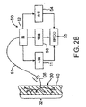
ここで、一般的な血管壁40内に配置された圧受容器30の概略図および圧反射系50の概略フローチャートを示す図2Bを参照されたい。圧受容器30は、先に考察した主要な動脈の動脈壁40内に大量に分布しており、全体として樹32を形成する。圧受容器樹32は、各々が神経38を介して圧受容器信号を脳52に伝達する、複数の圧受容器30を備える。圧受容器30は大量に分布しかつ血管壁40内で樹状に分岐しているので、個々の圧受容器樹32は、容易には識別できない。このために、図2Bに示す圧受容器30は、説明の目的上、主として概略的である。
Reference is now made to FIG. 2B which shows a schematic diagram of a
圧反射信号は、総称して圧反射系50と呼ぶことができる多くの身体系を活性化するために用いられる。圧受容器30(および他の圧受容器様受容器)は、神経系51を介して脳52に接続されている。これによって、脳52は、心拍出量を示す血圧の変化を検出することができる。心拍出量が要求量を満たすのに不十分である(すなわち、心臓11が十分な血液を送ることができない)場合、圧反射系50は、心臓11、腎臓53、血管54、および他の器官/組織を含む多くの身体系を活性化する。圧反射系50のそのような活性化は通常、神経ホルモンの活性の増大に対応する。具体的に述べれば、圧反射系50が神経ホルモン連鎖を開始し、この連鎖によって、心拍出量を増大させるために心拍数を増やしかつ収縮力を高めるように心臓11に信号が送られ、ナトリウムおよび水分を保持することによって血液量を増大させるように腎臓53に信号が送られ、血圧を上昇させるために収縮するように血管54に信号が送られる。心臓、腎臓および血管の応答によって血圧・心拍出量55が増大し、その結果心臓11の仕事量が増大する。逆に、患者の血圧が上昇している場合、通常、反対の圧反射反応が生じる。
The baroreflex signal is used to activate many body systems that can be collectively referred to as the
高血圧症、心不全、他の心臓血管疾患および腎機能異常の問題に対処するために、本発明は、圧反射系50を活性化して、過剰な血圧、自律神経系の活性および神経ホルモンの活性化を低下させる多くの装置、システムおよび方法を提供する。以下の説明の多くは、心血管の状態を処置するための圧反射活性化の利用に焦点を当てているが、しかしながら、本発明は、決してそのような用途に限定されるものではない。実際、種々の実施形態によれば、圧受容器活性化は、てんかんを処置するための発作活動の制御(米国特許出願第60/505121号に全体が記載されている)または疼痛管理および/もしくは鎮静(米国特許出願第60/513642号に全体が記載されている)のためなどの任意の他の適切な目的のために用いることができる。他の実施形態は、任意の他の適切な目的のための圧反射活性化を包含することができる。
In order to address the problems of hypertension, heart failure, other cardiovascular diseases and renal dysfunction, the present invention activates the
詳細には、本発明は、圧受容器30および他の圧反射構造物を活性化することができ、それにより血圧の上昇を示して身体の血圧ならびに交感神経系および神経ホルモンの活性化レベルを低下させ、かつ副交感神経系の活性化を高めるように脳52に信号を送り、これによって心血管系および他の身体系に対して有益な効果を有する多くの装置、システムおよび方法を提供する。先に述べたように、本発明の種々の実施形態は、圧受容器30、他の受容器、頸動脈洞神経線維のような1つまたはそれ以上の圧受容器に接続された神経線維、または圧反射を引き起こすための任意の他の適切な構造物を活性化することによって機能することができ、また活性化は、構造へ直接に、または構造の近傍に与えることができる。この種類の活性化を、本明細書において「圧反射活性化」と総称する。便宜上、語句「圧受容器を活性化する」は、直前に言及した圧反射活性化を引き起こすための構造のうちのいずれかを活性化することを総称するのにしばしば用いられ得る。
In particular, the present invention can activate
ここで図3を参照すると、本発明は、全体として、患者130に対して外部から刺激を付与して圧反射を引き起こし、1つまたはそれ以上の生理学的パラメータを測定するシステムを提供する。その後、測定されたパラメータを用いて、付与された刺激がどの程度まで圧反射を引き起こしたかを判定し、それによって植え込み型圧反射活性化装置が所与の患者において有することになる効能に関する情報を医師に提供することができる。通常、圧反射活性化/測定システムは、少なくとも1つの圧反射活性化装置132および少なくとも1つの生理学的パラメータ測定装置140を備える。種々の実施形態において、活性化装置132は、例えば、エネルギー伝達装置、頸動脈をマッサージするための機械力付与装置、1つまたはそれ以上の薬物を患者130に送達して圧反射を引き出すための薬物送達装置および/またはそれに類似する装置を備えることができる。任意の適切な装置または複数の装置の組み合わせを用いることができる。図3では、活性化装置132は、2本のリード線134を介して2つの電極136と連結されたエネルギーの電磁エネルギー源133を備える。代替的に、エネルギー源133は、超音波エネルギー源、マイクロ波エネルギー源、TENS装置、RFエネルギー源または任意の他の適切なエネルギー源を備えることができる。電極136は、超音波伝達部材または同種のもののような任意の他のエネルギー伝達部材を代替的に備えることができる。
Referring now to FIG. 3, the present invention generally provides a system for applying an external stimulus to a
電極136は患者130の頸部と連結された状態で示されているが、それらを、代替的に、圧反射を活性化するための任意の他の適切な位置に配置することもできる。例えば、それらは、圧受容器または圧受容器神経が存在する別の位置の近傍で患者に連結することもできる。あるいは、1つまたはそれ以上のエネルギー伝達部材を患者に接触しないように配置してもよい。1つだけのエネルギー伝達装置を包含するいくつかの実施形態および複数のエネルギー伝達装置を包含する他の実施形態については、任意の数のエネルギー伝達部材を用いることができる。言及したように、機械的刺激、薬物による活性化および/または同種のもののような、圧反射を活性化するための他の様式を用いてもよい。
Although the
測定装置140も同様に、任意の適切な装置または装置の組み合わせを備えることができる。示される実施形態では、測定装置140は血圧計であるが、パルスオキシメータ、スワンガンツカテーテル、ECG装置もしくはEEG装置、または同種のもののような任意の他の適切な装置を用いることができる。血圧、血圧の変化、心拍数、心拍出量、血管抵抗、発作活動、神経学的活動、痛覚、患者の鎮静または同種のもののような、圧反射を示す任意のパラメータを測定することができる。測定装置140を用いて、医師は、活性化装置132による刺激の付与によって圧反射が引き起こされた程度を判定することができ、これによって、植え込み型活性化装置が所望の結果を達成することになるかどうかを判断することができる。場合によっては、医師は、圧反射活性化が所与の患者には望ましくないことを決定することができ、その結果、活性化装置を植え込まないことを決定することになる。
The
いくつかの実施形態では、患者に対して複数の圧反射刺激を付与することができ、この刺激の付与後に得られた圧反射活性化を比較することができる。例えば、異なる強度および/または異なる位置から付与された刺激を比較することができ、それらの刺激の結果を記述するデータを医師に提供することができる。次いで、医師は、そのデータを用いて、1つまたはそれ以上の植え込み型活性化装置を配置するのに最適または望ましい位置を選択しかつ/または活性化装置において設定する強度を選択することができる。そのような工程を促進するために、いくつかの実施形態では、システムは、測定装置140によって取得された測定値を処理するためのプロセッサおよび/または医師であるユーザに有用なデータを提供するためのモニタもしくは他の読み出し機構をさらに備えることができる。
In some embodiments, multiple baroreflex stimuli can be applied to a patient, and baroreflex activation obtained after the application of the stimulus can be compared. For example, stimuli applied from different intensities and / or different locations can be compared and data describing the results of those stimuli can be provided to the physician. The physician can then use the data to select an optimal or desirable location for placing one or more implantable activation devices and / or to select a strength to set in the activation device. . In order to facilitate such a process, in some embodiments, the system provides a processor for processing the measurements obtained by the
所与の患者が植え込まれた圧反射刺激装置に対し好ましく反応することを医師がひとたび判断すれば、次の工程で、そのような装置を実際に植え込むことができる。以下の説明は、圧反射活性化のための多くの植え込み型装置に焦点を当てている。しかしながら、本発明は、決して以下に説明する植え込み型装置の使用に限定されるものではない。実際、任意の適切な植え込み型装置を、本発明の方法またはシステムの一部として必要に応じて用いることができる。例えば、いくつかの実施形態では、植え込み型の装置またはシステムは、処置中の患者の身体の外部に配置される1つまたはそれ以上の外部構成要素もしくは外部部品も備えることができる。 Once the physician has determined that a given patient will respond favorably to the implanted baroreflex stimulation device, such a device can actually be implanted in the next step. The following description focuses on a number of implantable devices for baroreflex activation. However, the present invention is in no way limited to the use of the implantable device described below. In fact, any suitable implantable device can be used as needed as part of the method or system of the present invention. For example, in some embodiments, an implantable device or system can also include one or more external components or parts that are located external to the patient's body being treated.
このように、ここで図4を参照すると、本発明は、一般に以下の方法で動作する制御システム60、圧反射活性化装置70、およびセンサ80(必要に応じて)を備えるシステムを全体として提供する。センサ80は、圧反射系を調節する必要性を示すパラメータ(例えば心血管機能)を必要に応じて感知および/または監視し、このパラメータを示す信号を生成する。制御システム60は、受信したセンサ信号の関数としての制御信号を生成する。制御信号により、圧反射活性化装置70が作動、停止または別な方法で調節される。一般に、装置70の作動の結果、圧受容器30(または他の圧反射構造)が活性化する。あるいは、圧反射活性化装置70を停止または調節することによって、圧受容器30の活性化を引き起こしたかもしくはそれを調節することができる。圧反射活性化装置70は、電気的手段を用いて圧受容器30を活性化する多種多様な装置を備えることができる。従って、センサ80が圧反射系の活性を調節する必要性(例えば血圧過剰)を示すパラメータを検出すると、制御システム60が圧反射活性化装置70を調節する(例えば作動させる)ための制御信号を生成し、それにより脳52によって明らかな血圧過剰であると認知される圧反射信号が誘発される。センサ80が正常な身体機能(例えば正常な血圧)を示すパラメータを検出すると、制御システム60は、圧反射活性化装置70を調節する(例えば停止する)ための制御信号を生成する。
Thus, referring now to FIG. 4, the present invention generally provides a system comprising a
先に述べたように、圧反射活性化装置70は、電気的手段を用いて圧受容器30を活性化する多種多様な装置を備えることができる。本発明の圧反射活性化装置70は、圧受容器30にわたって電位を変えることによって1つまたはそれ以上の圧受容器30を直接活性化する電極構造を備える。圧受容器30を取り巻く組織にまたがる電位を変えることによって、周囲組織を伸張または他の方法で変形させ、これによって圧受容器30を機械的に活性化し得ることが可能であり、その場合、本発明の伸張可能で弾性を有する電極構造は、顕著な利点を提供することができる。
As previously mentioned,
本発明の電極構造の特定の実施形態のすべてが移植に適しており、低侵襲性の外科的アプローチを用いて移植されるのが好ましい。圧反射活性化装置70は、圧受容器30が存在するあらゆる部位に配置することができる。そのような潜在的移植部位は、大動脈弓12、頸動脈洞20近傍の総頸動脈18/19内、鎖骨下動脈13/16内、腕頭動脈22内、または他の動脈部位内もしくは静脈部位内など、多数存在する。本発明の電極構造は、それらが、圧受容器30の位置にあるかまたはその近傍にある血管構造物の上もしくはそれを覆って配置されるように、植え込まれる。圧反射活性化装置70の電極構造は、圧受容器30が圧反射系50に顕著な影響力を有する、右頸動脈洞20および/または左頸動脈洞の近傍(総頸動脈の分岐部近傍)ならびに/もしくは大動脈弓12の近傍に植え込まれるのが好ましい。単に説明として、頸動脈洞20近傍に配置された圧反射活性化装置70を参照して本発明を説明する。
All of the specific embodiments of the electrode structure of the present invention are suitable for implantation and are preferably implanted using a minimally invasive surgical approach. The
任意選択的なセンサ80は、電気センサケーブルまたは電気センサリード線82によって制御システム60に作動可能に連結されている。センサ80は、圧反射系の活性を調節する必要性を示すパラメータを測定または監視する任意の適切な装置を備えることができる。例えば、センサ80は、ECG、血圧(収縮期、拡張期、平均血圧または脈圧)、血液流量、血液流速、血液pH、O2含有量またはCO2含有量、混合静脈血酸素飽和度(SVO2)、血管作用、神経活動、組織活動、身体の動き、活性レベル、呼吸、または組成を測定する生理学的変換器または計測器を備えることができる。センサ80用に適した変換器または計測器の例としては、ECG電極、圧電式圧力変換器、超音波流速変換器、超音波流量変換器、熱希釈式流速変換器、容量式圧力変換器、膜pH電極、光学検出器(SVO2)、組織インピーダンス計(電気的)、または歪みゲージが挙げられる。1つセンサ80のみを図示しているが、同じまたは異なる位置の、同じまたは異なる種類の複数のセンサ80を用いることができる。
血管の周りに配置することができる植え込み型血圧測定装置の例は、Mieselらに付与された米国特許第6,106,477号に開示されており、その開示内容全体が参考として本明細書において援用される。皮下ECGモニタの例は、REVEAL ILRという商品名でMedtronicから入手可能であり、PCT公開第WO98/02209号に開示されており、その開示内容全体が参考として本明細書において援用される。他の例は、米国特許第5,987,352号および第5,331,966号に開示されており、それらの開示内容全体が参考として本明細書において援用される。周囲圧力を利用して絶対血圧を測定する装置および方法への参照の例は、Halperinらに付与された米国特許第5,810,735号、Goedekeに付与された米国特許第5,904,708号、およびBrockwayらに付与されたPCT公開第WO00/16686号に開示されており、それらの開示内容全体が参考として本明細書において援用される。本明細書において説明するセンサ80は、ほぼ同じ目的に役立つこれらの装置または他の装置のいずれかの形をとることができる。
An example of an implantable blood pressure measurement device that can be placed around a blood vessel is disclosed in US Pat. No. 6,106,477 to Miesel et al., The entire disclosure of which is hereby incorporated herein by reference. Incorporated. An example of a subcutaneous ECG monitor is available from Medtronic under the trade name REVEAL ILR and is disclosed in PCT Publication No. WO 98/02209, the entire disclosure of which is incorporated herein by reference. Other examples are disclosed in US Pat. Nos. 5,987,352 and 5,331,966, the entire disclosures of which are hereby incorporated by reference. Examples of references to devices and methods for measuring absolute blood pressure using ambient pressure are US Pat. No. 5,810,735 to Halperin et al., US Pat. No. 5,904,708 to Goedeke. And PCT Publication No. WO 00/16686 to Blockway et al., The entire disclosures of which are incorporated herein by reference. The
センサ80は、目的のパラメータを容易に確認することができるように、大動脈弓12、総頸動脈14/15、鎖骨下動脈13/16または腕頭動脈22のような主要な動脈の内部もしくはその上、あるいは心室11内に配置することができる。センサ80は、用いられる変換器または計測器の種類に応じて、動脈、静脈もしくは神経(例えば迷走神経)の内部またはその上などの身体の内部に配置してもよく、身体の外部に配置してもよい。センサ80は、圧反射活性化装置70から分離していても、それと組み合わせられていてもよい。単に説明のためにのみ、センサ80を、右鎖骨下動脈13上に配置された状態で示す。
The
一例として、制御システム60は、プロセッサ63およびメモリ62を備える制御ブロック61を含む。制御システム60は、センサケーブル82を介してセンサ80に接続されている。制御システム60はまた、電気制御ケーブル72を介して圧反射活性化装置70にも接続されている。従って、制御システム60は、センサケーブル82を介して、センサ80からセンサ信号を受信し、制御ケーブル72を介して、圧反射活性化装置70に制御信号を伝送する。
As an example, the
本システムの構成要素60/70/80は、ケーブル72/82を介して直接連結してもよく、RF信号トランシーバ、超音波トランシーバあるいは流電(galvanic)結合のような間接的手段によって連結してもよい。そのような間接的相互接続装置の例は、Funkeに付与された米国特許第4,987,897号およびFunkeに付与された米国特許第5,113,859号に開示されており、それらの開示内容全体が参考として本明細書において援用される。
The
メモリ62は、センサ信号、制御信号、および/または入力装置64によって提供された値ならびに命令に関連するデータを含むことができる。メモリ62は、制御信号とセンサ信号との間の1つまたはそれ以上の機能もしくは関係を定義する1つまたはそれ以上のアルゴリズムを含むソフトウェアも含むことができる。本アルゴリズムは、センサ信号またはその数学的導出値に応じて、作動または停止を要求することができる。本アルゴリズムは、センサ信号が所定閾値の下限を下回った場合、所定閾値の上限を上回った場合またはセンサ信号が特定の生理学的事象を示した場合に、作動制御信号もしくは停止制御信号を要求することができる。本アルゴリズムは、センサ入力値によって決定されたとおりに、動的に閾値を変更することができる。
先に述べたように、圧反射活性化装置70は、必要に応じて機械的、熱的、化学的、生物学的または他の共活性化と組み合わせて、圧受容器30および/または他の圧反射構造物を電気的に活性化する。いくつかの例では、制御システム60は、圧反射活性化装置70に対して所望の電力モードを提供するためのドライバ66を備える。例えば、ドライバ66は電力増幅器または同種のものを備えることができ、ケーブル72は、電気リード線を備えることができる。別の例では、特にプロセッサ63が圧反射活性化装置70の低レベルの電気的作動に対して十分に強い電気信号を生成する場合、ドライバ66は必要ではないかもしれない。
As previously mentioned,
制御システム60は、センサ80、または組み込まれ得るかもしくは電極組立体であり得る心拍数センサのような他のセンサからのフィードバックを利用する閉ループとして、あるいは入力装置64によって受信された再プログラミングコマンドを利用する開ループとして動作することができる。制御システム60の閉ループ動作には変換器80からのいくらかのフィードバックを利用するのが好ましいが、フィードバックなしで開ループモードで動作することもできる。入力装置64によって受信されたプログラミングコマンドは、制御信号、出力活性化パラメータに直接影響を及ぼすことも、メモリ62内に含まれたソフトウェアおよび関連するアルゴリズムを変更することもできる。処置中の医師および/または患者は、入力装置64にコマンドを提供することができる。ディスプレイ65を用いて、センサ信号、制御信号および/またはメモリ62内に含まれたソフトウェア/データを閲覧することができる。
The
制御システム60によって生成される制御信号は、メモリ62内に含まれたアルゴリズムによって要求されるとおりに、連続的、周期的、交互的、一時的またはそれらの組み合わせであり得る。連続的制御信号は、一定パルス、一定パルス列、誘発パルスおよび誘発パルス列を含む。周期的制御信号の例には、指定開始時刻(例えば、分、時間、または日の組み合わせによって指定された各周期の開始時点)および指定持続時間(例えば、秒、分、時間、または日の組み合わせ)を有する上述の連続的制御信号の各々が含まれる。交互的制御信号の例には、右出力チャネルと左出力チャネルとの間で交代する上述の連続的制御信号の各々が含まれる。一時的制御信号の例には、症状の発現(例えば、医師/患者、特定の閾値を上回る血圧の上昇/低下、特定のレベルを上回る/下回る心拍数などによる作動)によって誘発される上述の連続的制御信号の各々が含まれる。
The control signals generated by the
制御システム60によって管理される刺激療法は、長期的効能を促進するように選択することができる。中断されないかまたは変化のない圧受容器30の活性化は、結果として圧受容器および/または圧反射系の応答性の経時低下をもたらし、それにより治療の長期的効果を低減させる可能性があることが理論付けられている。従って、刺激療法は、治療効力が好ましくは数年間維持されるように圧反射活性化装置70を作動、停止または別の方法で調節するように選択することができる。
Stimulation therapy managed by the
長期にわたって治療効果を維持することに加え、本発明の刺激療法は、システム60の所要電力/電力消費を低減するように選択することができる。以下により詳細に説明するように、本刺激療法は、圧反射活性化装置70が最初は相対的により高いエネルギーレベルおよび/または電力レベルで作動され、その後は相対的により低いエネルギーレベルおよび/または電力レベルで作動されるように要求することができる。第1のレベルによって所望の初期治療効果が達成され、第2の(より低い)レベルによって、所望の治療効果が長期にわたって維持される。所望の治療効果が最初に達成された後に、エネルギーレベルおよび/または電力レベルを低減することにより、活性化装置70によって要求または消費されるエネルギーも長期にわたって低減される。これは、寿命がより長くかつ/またはサイズが縮小された(電源および関連部品のサイズの縮小による)システムとなることに関連し得る。
In addition to maintaining a therapeutic effect over time, the stimulation therapy of the present invention can be selected to reduce the power / power consumption of the
長期的効能を促進しかつ所要電力/電力消費を低減する刺激療法に対する最初の一般的手法は、圧反射活性化装置70に第1の相対的により高いエネルギーおよび/または電力の出力レベルを有するように制御信号を生成する工程と、その後圧反射活性化装置70に第2の相対的により低いエネルギーおよび/または電力の出力レベルを有させるように制御信号を変更する工程とを含む。第1の出力レベルを、所望の初期効果(例えば心拍数および/または血圧の低下)を達成するように選択し、かつ十分な時間維持することができ、その後、該出力レベルを、所望の期間所望の効果を維持するのに十分な時間、第2のレベルに低下させることができる。
The first general approach to stimulation therapy that promotes long-term efficacy and reduces the required power / power consumption is to have the
例えば、第1の出力レベルがX1の電力値および/またはエネルギー値を有する場合、第2の出力レベルは、X2がX1よりも小さい、X2の電力値および/またはエネルギー値を有することができる。いくつかの例では、第1のレベルが「オン」で第2のレベルが「オフ」となるように、X2をゼロに等しくすることができる。電力およびエネルギーは、2つの異なるパラメータを指し、該パラメータ(電力またはエネルギー)のうちの1つの変更を他方のパラメータにおける同一もしくは類似する変更と関連付けることはできない場合もあることが分かる。本発明では、これらのパラメータのうちの1つまたは両方の変更が長期的効能を促進するという所望の結果を得るのに好適であり得ると考えている。 For example, if the first power level has a power value and / or energy value of X1, the second power level can have a power value and / or energy value of X2, where X2 is less than X1. In some examples, X2 can be equal to zero such that the first level is “on” and the second level is “off”. It will be appreciated that power and energy refer to two different parameters and that changing one of the parameters (power or energy) may not be associated with the same or similar change in the other parameter. The present invention believes that changing one or both of these parameters may be suitable for obtaining the desired result of promoting long-term efficacy.
2つより多いレベルを用いることができるとも考えられる。さらなるレベルの各々は、出力エネルギーまたは出力電力を増大させて所望の効果を達成するか、もしくは出力エネルギーまたは出力電力を減少させて所望の効果を保持することができる。例えば、いくつかの例では、より低い電力レベルまたはエネルギーレベルで所望の効果を維持することができる場合、出力レベルをさらに低下させることが望ましくあり得る。別の例では、特に、所望の効果が減少しつつあるかまたは維持されていない場合、所望の効果が回復するまで出力レベルを増大させ、その後出力レベルを低下させて該効果を維持することがおそらく望ましくあり得る。 It is also contemplated that more than two levels can be used. Each of the additional levels can increase the output energy or output power to achieve the desired effect, or decrease the output energy or output power to maintain the desired effect. For example, in some instances, it may be desirable to further reduce the output level if the desired effect can be maintained at a lower power or energy level. In another example, particularly if the desired effect is diminishing or not maintained, the output level can be increased until the desired effect is restored, and then the output level can be decreased to maintain the effect. May be desirable.
各レベルからの移行は、ステップ関数(例えば、単一のステップまたは一連のステップ)、ある期間にわたる段階的移行、またはそれらの組み合わせとすることができる。さらに、信号レベルは、先に考察したように、連続的、周期的、交互的、または一時的とすることができる。 The transition from each level can be a step function (eg, a single step or a series of steps), a gradual transition over a period of time, or a combination thereof. Further, the signal level can be continuous, periodic, alternating, or temporary, as discussed above.
非変調信号を用いた電気的活性化では、圧反射活性化装置70の出力(電力またはエネルギー)レベルは、出力信号の電圧レベル、電流レベルおよび/または信号継続時間を調整することによって変更することができる。圧反射活性化装置70の出力信号は、例えば、定電流、または定電圧とすることができる。出力信号が例えば一連のパルスを含む、変調信号を用いた電気的活性化の実施形態では、いくつかのパルス特性を個々にもしくは組み合わせて変更し、出力信号の電力レベルまたはエネルギーレベルを変更することができる。そのようなパルス特性には,限定するものではないが、パルス振幅(PA)、パルス周波数(PF)、パルス幅またはパルス持続時間(PW)、パルス波形(正方形、三角形、正弦曲線など)、パルス極性(双極電極用)およびパルス位相(単相、二相)が挙げられる。
For electrical activation using an unmodulated signal, the output (power or energy) level of the
出力信号がパルス列を含む電気的活性化では、その全開示内容が参考として本明細書において援用される同時係属中の出願第09/964,079号に記載されているように、上述のパルス特性に加えて、いくつかの他の信号特性を変更することができる。 For electrical activation in which the output signal includes a pulse train, the above-mentioned pulse characteristics are described as described in co-pending application 09 / 964,079, the entire disclosure of which is incorporated herein by reference. In addition, several other signal characteristics can be changed.
図5Aおよび図5Bに、血管外導電性構造または電極302の形態の圧反射活性化装置300の概略図を示す。電極構造302は、血管壁を取り囲むことができるコイル、ブレードまたは他の構造を備えることができる。あるいは、電極構造302は、血管壁の外側表面を囲むように分布した1つまたはそれ以上の電極パッチを備えていてもよい。電極構造302が血管壁の外側表面に配置されているために、血管内送達技術は実際的ではないかもしれないが、低侵襲手術手技には事足りる。血管外電極構造302は、電気リード線304を介して制御システム60のドライバ66から直接、または先に引用により本明細書に組み込まれた同一出願人による出願第10/402393号に記載されているように、インダクタ(図示せず)を用いて間接的に電気信号を受信することができる。
5A and 5B show a schematic diagram of a
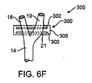
ここで、図4Aおよび図4Bを参照して説明した圧反射活性化装置300のような、血管外電気的活性化の実施形態用の頸動脈洞20を取り囲む電極の種々の可能な配置の概略図を示す図6A〜図6Fを参照されたい。以下に図示して説明する電極設計は、頸動脈洞またはその近傍における頸動脈への接続に特に適するものであり得、不要な組織刺激を最小限にするように設計することができる。
Here, an overview of various possible arrangements of electrodes surrounding the
図6A〜図6Fに、総頸動脈14、外頚動脈18および内頚動脈19を含む頸動脈を示す。頸動脈洞20の位置は、一般に分岐部のすぐ遠位の内頸動脈19上に位置するかまたは総頸動脈14から内頸動脈19へ分岐部を跨いで伸びる目印の膨隆21によって識別することができる。
6A-6F illustrate the carotid artery including the common
頸動脈洞20、および特に頸動脈洞の膨隆21は、血管壁内に比較的高密度の圧受容器30(図示せず)を含むことができる。この理由により、活性化装置300の電極302を洞の膨隆21上および/またはそれを囲むように配置して、圧受容器の反応性を最大化しかつ不要な組織刺激を最小限に抑えるのがおそらく望ましくあり得る。
The
装置300および電極302は単に概略的なものであり、頸動脈洞20ならびに洞の膨隆21の上および/または周囲の電極302のさまざまな位置を示すために、それらの一部のみを示すことができるものであることを理解されたい。本明細書に説明する実施形態の各々において、電極302は、単極、双極、または三極(陽極−陰極−陽極または陰極−陽極−陰極のセット)とすることができる。特定の血管外電極設計を以下により詳細に説明する。
図6Aでは、血管外電気的活性化装置300の電極302は、洞20の外周の一部または全部を囲むように輪状に伸びている。実際の使用においては、図示の電極構成を逆転させるのが望ましいことが多いであろう。図6Bでは、血管外電気的活性化装置300の電極302は、洞20の外周の一部または全部を囲むようにらせん状に伸びている。図6Bに示すらせん状配置では、電極302を任意の回数だけ洞20に巻き付け、所望の電極302の接触および被覆を構築することができる。図6Aに示す輪状配置では、一対の電極302を洞20に巻き付けてもよく、図6Cに示すように、複数の電極対302を洞20に巻き付けて、より大きな電極302の接触および被覆を構築してもよい。
In FIG. 6A, the
複数の電極対302は、洞20または膨隆21の近位の一点から洞20または膨隆21の遠位の一点まで伸びて、洞20領域全体にわたる圧受容器30の活性化を確保することができる。電極302は、以下により詳細に論じるように、単一のチャネルまたは複数のチャネルに接続することができる。複数の電極対302は、洞20の特定の部位を標的化して圧受容器の反応性を高めるため、または活性化に対する組織領域の曝露を低減して圧受容器の反応性を長期間維持するために、選択的に活性化することができる。
The plurality of electrode pairs 302 can extend from a point proximal to the
図6Dでは、電極302は、洞20の外周全体を囲むように交差状に伸びている。電極302の交差状配置により、頸動脈洞20の周りに、内頸動脈19と外頸動脈18の両方との接触が確立される。同様に、図6Eでは、電極302は、分岐部において、またいくつかの例では総頸動脈14において、内頸動脈19および外頸動脈18を含め、洞20の外周の全部または一部を囲むように伸びている。図6Fでは、電極302は、分岐部の遠位において、内頸動脈19および外頸動脈18を含め、洞20の外周の全部または一部を囲むように伸びている。図6Eおよび図6Fでは、血管外電気的活性化装置300は、基板または基部構造306を含むように示されており、以下により詳細に説明するように、該基板または基部構造306は、電極302を封入して絶縁することができ、かつ洞20に取り付ける手段を提供する。
In FIG. 6D, the
図6A〜図6Fを参照した先の考察から、頸動脈洞20および関連する生体構造に対して、活性化装置300の電極302のための多くの適した配置があることは明らかであるはずである。上に挙げた例の各々において、電極302は、頸動脈構造物の一部に巻き付けられており、これにより、弛緩した形状(例えばまっすぐな形状)からの電極302の変形が必要となる可能性がある。そのような変形を低減または排除するために、電極302および/または基部構造306は、付着点においける頸動脈解剖構造の形状に実質的に適合する弛緩した形状を有することができる。換言すれば、電極302および基部構造または裏当て306は、実質的に弛緩した状態で頸動脈解剖構造に適合するようにあらかじめ成形することができる。あるいは、電極302は、電極302のひずみ量を低減する形状および/または配向を有することができる。以下により詳細に説明するように、必要に応じて、裏当てもしくは基部構造306は、頸動脈洞または他の血管構造物への巻き付けおよび適合を促進するために、弾性あるいは伸縮性であり得る。
From the previous discussion with reference to FIGS. 6A-6F, it should be apparent that there are many suitable arrangements for the
例えば、図7では、電極302は、蛇行形状または波状形状を有するように示されている。電極302の蛇行形状により、頸動脈構造物に巻き付けられた際に電極材料に見られる歪み量が減少する。さらに、電極の蛇行形状により、頸動脈組織との電極302の接触表面積が増大する。代案として、図8に示すように、巻き付け方向に対して実質的に垂直と(すなわち、頸動脈の軸線と実質的に平行に)なるように電極302を配置してもよい。この代案では、電極302は各々、長さが幅または直径よりも実質的に大きい長さ、および幅または直径を有する。電極302の各々は、その長さと平行な長手方向軸線を有し、この長手方向軸線は、巻き付け方向に直角で、装置300が巻き付けられる頸動脈の長手方向軸線と実質的に平行である。前述の複数電極の実施形態に関しては、電極302は、以下により詳細に考察するように、単一のチャネルまたは多数のチャネルに接続することができる。
For example, in FIG. 7, the
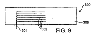
ここで、血管外電気的活性化装置300用の種々のマルチチャネル電極を概略的に示す図9〜図12を参照されたい。図8に、互いに隣接しかつ互いに平行に伸びる6つの別個の細長い電極302を含む6チャネル電極組立体を示す。電極302は各々、マルチチャネルケーブル304に接続されている。電極302のうちのいくつかは共通であり得、それによりケーブル304内に必要な芯線の数が低減されている。
Reference is now made to FIGS. 9-12, which schematically illustrate various multichannel electrodes for the extravascular
基部構造または基板306は、おそらくはポリエステル織物のような可撓性の材料で補強されたシリコーンのような、移植に適した、可撓性で電気絶縁性の材料を備えることができる。基部306は、頸動脈洞20に隣接する頸動脈のうちの1つまたはそれ以上の外周の全部(360°)または周りの一部(すなわち、360°未満)に巻き付けるのに適切な長さを有することができる。電極302は、頸動脈洞20に隣接する頸動脈のうちの1つまたはそれ以上の一部(すなわち、例えば270°、180°または90°など360°未満)を囲んで伸びることができる。この目的を達するために、電極302は、基部206の長さ未満の長さ(例えば、75%、50%または25%)を有することができる。電極302は、それを周りに配置する頸動脈の軸線にほぼ垂直な基部306の長さに対して平行であっても、垂直であっても、斜めでもよい。基部構造または裏当ては、典型的には少なくとも部分的にシリコーン、ラテックス、または他のエラストマーからなり、弾性(すなわち伸縮性)となるのが好ましい。そのような弾性構造体を補強する場合、補強材は、伸縮して血管表面に適合する基部の能力を該補強材が妨害しないように配置されなければならない。
The base structure or
電極302は、プラチナのような導電性で放射線不透過性の材料で形成された円形のワイヤ、長方形のリボンまたは箔を備えることができる。基部構造306は、血管外頸動脈洞組織への電気的接続用の露出領域のみを残し、実質的に電極302を封入している。例えば、各電極302は、基部206内に部分的に埋め込むことができ、頸動脈組織への電気的接続用に、その長さの全部または一部に沿って、一面を露出させておくことができる。頸動脈組織を通る電気経路は、一対以上の細長い電極302によって規定することができる。
本明細書において別の箇所で説明したように、図9〜図12を参照したすべての実施形態で、マルチチャネル電極302は、頸動脈洞20の特定の領域をマッピングおよび標的し、最大の圧受容器反応性を得るように活性化するための最善の電極302の組み合わせ(例えば、個々の対、または対の群)を決定するために、選択的に活性化することができる。さらに、本明細書において別の箇所で説明したように、マルチチャネル電極302は、活性化に対する組織領域の曝露を低減し、長期にわたって効能を維持するために、選択的に活性化することができる。これらの目的に対しては、2つより多い電極チャネルを用いるのが有益であり得る。あるいは、電極302を単一のチャネルに接続してもよく、それによって、圧反射が洞20領域全体にわたって均一に活性化される。
As described elsewhere herein, in all embodiments with reference to FIGS. 9-12, the
代替的なマルチチャネル電極設計を図10に示す。この実施形態では、装置300は、4つのチャネルコネクタ303を介して16本のチャネルケーブル304に接続された16個の個々の電極パッド302を備える。この実施形態では、円形の電極パッド302が基部構造306によって部分的に封入されており、各ボタン電極302の一面が頸動脈組織への電気的接続用に露出されている。この配置に関しては、頸動脈組織を通る電気経路は、電極パッド302の1つまたはそれ以上の対(双極)もしくは群(三極)によって規定することができる。
An alternative multi-channel electrode design is shown in FIG. In this embodiment, the
マルチチャネルパッド型電極設計の変形形態を図10に示す。この実施形態では、装置300は、同心電極パッド302/305と総称することができる、16個のリング305で取り囲まれた16個の個々の円形パッド電極302を備える。パッド電極302は、4つのチャネルコネクタ303を介して17チャネルのケーブル304に接続され、リング305は、単一チャネルコネクタ307を介して、共通の17チャネルのケーブル304に接続されている。この実施形態では、円形状の電極302およびリング305は、基部構造306によって部分的に封入されて、各パッド電極302の一面および各リング305の一面を頸動脈組織への電気的接続用に露出させる。代案として、リング305を共通に接続し、2つのリング305が各電極302を取り囲んでいてもよい。これらの配置では、頸動脈組織を通る電気経路を一組またはそれ以上のパッド電極302/リング305のセット間に規定し、局所電気経路を生成することができる。
A variation of the multi-channel pad electrode design is shown in FIG. In this embodiment, the
マルチチャネルパッド電極設計の別の変形形態を図12に示す。この実施形態では、装置300は、チャネルケーブル304に接続された制御用ICチップ310を含む。制御用チップ310も、4つのチャネルコネクタ303を介して16個の個々のパッド電極302に接続されている。制御用チップ310は、コードシステムを用いることによってケーブル304内のチャネル数を減らすことを可能にする。制御システム60がコード化した制御信号を送信し、それをチップ310が受信する。チップ310は、コードを変換し、該コードに従って、選択された電極302の対を使用可能または使用不可能とする。
Another variation of the multi-channel pad electrode design is shown in FIG. In this embodiment, the
例えば、制御信号は、各パルスが異なるコードを含むパルス波形を含むことができる。各パルスに対するコードにより、チップ310が、一対以上の電極を使用可能とし、残りの電極を使用不可能とする。これにより、そのパルスと共に送信されたコードに対応する使用可能な電極対にのみ、該パルスが伝達される。後続の各パルスは、チップ310が異なるコードに対応する異なる電極302のセットを使用可能および使用不可能とするように、先行パルスとは異なるコードを有する。従って、各電極302に対して別個のチャネルをケーブル304内に設ける必要なく、制御用チップ310を用いて、実質的に任意の数の電極対を選択的に活性化することができる。ケーブル304内のチャネルの数を減らすことにより、そのサイズおよびコストを削減することができる。
For example, the control signal can include a pulse waveform where each pulse includes a different code. The code for each pulse allows the
必要に応じて、図4を参照して説明したものと同一の機能を生かし、ICチップ310をフィードバックセンサ80に接続してもよい。さらに、1つまたはそれ以上の電極302を、活性化用に使用可能とされていないときに、フィードバックセンサとして用いることができる。例えば、そのようなフィードバックセンサ電極を用いて、血管壁内の電気伝導を測定または監視し、ECGに類似したデータを提供することができる。あるいは、そのようなフィードバックセンサ電極を用いて、脈圧の間の血液量の変化によるインピーダンスの変化を感知し、心拍数、血圧、または他の生理学的パラメータを示すデータを提供することができる。
If necessary, the
ここで、支持用カラーまたは支持用固定具312を含む血管外電気的活性化装置300を概略的に示す図13を参照されたい。この実施形態では、活性化装置300は、頸動脈洞20において内頸動脈19に巻き付けられ、支持用カラー312が、総頸動脈14に巻き付けられている。活性化装置300は、ゆるいつなぎ綱(tether)として機能するケーブル304によって支持用カラー312に接続されている。この配置では、カラー312は、例えば制御システム60および/またはドライバ66の動きによって生じる可能性のある、支持用カラーの近位のケーブル304によって伝達される動きおよび力から活性化装置を隔離する。支持用カラー312の代案として、張力緩和装置(図示せず)を、ケーブル304と基部306との間の接合部で、活性化装置300の基部構造306に接続することができる。いずれかの手法で、頸動脈解剖構造に対する装置300の位置を、本システムの他の部品の動きにもかかわらず、よりよく維持することができる。
Reference is now made to FIG. 13, which schematically illustrates an extravascular
この実施形態では、活性化装置300の基部構造306は、成形チューブ、チューブ状射出成形品、または図に示すような、縫合部309を有する縫合フラップ308を用いてチューブ状に巻いたシート材料を備えることができる。基部構造306は、シリコーンのような可撓性で生体適合性を有する材料で形成することができ、DACRON(登録商標)の商品名で入手可能なポリエステル繊維のような可撓性材料で補強して複合構造を形成することができる。基部構造306の内径は、例えば6mm〜8mmなど、移植の位置で頸動脈の外径に一致することができる。基部構造306の壁厚は、例えば1mm未満など、可撓性および薄型を維持するために、極めて薄くすることができる。装置300が洞の膨隆21の周りに配置されるべき場合、支持体の追加および配置の支援のために、対応する形状の膨隆を基部構造内に形成することができる。
In this embodiment, the
電極302(点線で示す)は、プラチナまたはプラチナイリジウムのような、導電性で放射線不透過性の材料で形成された円形のワイヤ、長方形のリボンまたは箔を備えることができる。電極は、頸動脈組織への電気的接続用に電極の一部を露出させた状態で、基部構造306内に成形してもよく、その内径に接着接続してもよい。電極302は、短絡を回避するために、基部構造306の内側周囲全体よりも少ない範囲(例えば300°)を包囲することができる。電極302は、前述の形状および配置のいずれを有してもよい。例えば、図13に示すように、各々が1.5mmの間隔をおいた1mmの幅を有する2つの長方形リボン電極302を用いてもよい。
Electrode 302 (shown in dotted lines) can comprise a round wire, rectangular ribbon or foil formed of a conductive, radiopaque material, such as platinum or platinum iridium. The electrode may be molded into the
支持用カラー312は、基部構造306と同様に形成することができる。例えば、支持用カラーは、成形チューブ、チューブ状射出成形品、または図に示すような、縫合部313を有する縫合フラップ315を用いてチューブ状に巻いたシート材料を備えることができる。支持用カラー312は、補強して複合構造を形成することができる、シリコーンのような可撓性で生体適合性を有する材料で形成することができる。ケーブル304は、支持用カラー312と活性化装置300との間のケーブル304にたるみを残して、支持用カラー312に固定されている。
The
本明細書に説明するすべての実施形態において、縫合または他の固定手段を用いて、活性化装置を血管壁に固定するのが望ましくあり得る。例えば、縫合部311を用いて、頸動脈解剖構造(または圧受容器、神経繊維または同種のものを含む他の血管部位)に対する電気的活性化装置300の位置を維持することができる。そのような縫合部311は、基部構造306に接続し、血管壁の全部または一部を貫通することができる。例えば、縫合部311は、血管壁の外膜を通じて基部構造306に通し、次いで結びつけられ得る。基部構造306がパッチを備えるかまたは他の方法で頸動脈組織を部分的に取り囲む場合、基部構造の隅および/または端部を、それらの間に均等に分布したさらなる縫合部によって縫合することができる。基部構造306を介した穴または引裂の伝播を最小限に抑えるために、ポリエステル繊維のような補強材を、シリコーン材料内に埋め込むことができる。縫合に加え、例えばステープラまたは生体適合性接着剤などの他の固定手段を用いることができる。
In all embodiments described herein, it may be desirable to secure the activation device to the vessel wall using sutures or other securing means. For example, the
ここで、スパイン317によって相互に接続された1つまたはそれ以上の電極リブ316を含む代替的血管外電気的活性化装置300を概略的に示す図14を参照されたい。必要に応じて、1つまたはそれ以上の(非電極)リブ316を有する支持用カラー312を用いて、支持用カラー312の近位のケーブル304によって伝達される動きおよび力から活性化装置300を隔離することができる。
Reference is now made to FIG. 14, which schematically illustrates an alternative extravascular
活性化装置300のリブ316は、頸動脈洞20に隣接する内頸動脈19のような頸動脈解剖構造の周りにフィットする寸法を有する。同様に、支持用カラー312のリブ316は、頸動脈洞20の近位の総頸動脈14のような頸動脈解剖構の周りにフィットする寸法を有することができる。リブ316を分離し、頸動脈組織上に配置し、次いでそれを囲むように閉鎖して、装置300を頸動脈解剖構に固定することができる。
The
装置300のリブ316の各々が、その内側表面上に、頸動脈組織への電気的接続用の電極302を含む。リブ316は、内側部分のみが血管壁に対して露出された状態の、電極302を囲む絶縁体を提供する。電極302は、スパイン317を通じて、マルチチャネルケーブル304に連結されている。スパイン317は、支持を提供することがそれらの機能であるために電極を含まない支持用カラー312の、リブ316へのつなぎ綱としても機能する。図9〜図12を参照して論じたマルチチャネル電極302の機能は、この実施形態にも同等に適用が可能である。
Each of the
リブ316の端部は、頸動脈の周りに配置した後に接続(例えば縫合)してもよく、図に示すように開放したままであってもよい。端部を開放したままとする場合、頸動脈の周りに機械的ロックを確保するために、リブ316を比較的堅い材料で形成するとよい。例えば、リブ316は、ポリエチレン、ポリプロピレン、PTFE、または他の類似した絶縁性および生体適合性の材料で形成することができる。代替的に、金属材料が電極302から電気的に絶縁されるならば、ステンレススチールまたはニッケルチタニウム合金のような金属でリブ316を形成してもよい。さらに別の代案として、リブ316は、金属の(例えば、ステンレススチール、ニッケルチタニウム合金など)補強材によって構造的に一体化された、絶縁性および生体適合性の高分子材料を含んでもよい。この後者の代案では、電極302は、金属の補強材を備えることができる。
The ends of the
ここで、血管外電気的活性化装置300用の電極組立体の具体例を概略的に示す図15を参照されたい。この特定の例では、基部構造306は、5.0インチの長さ、0.007インチの厚み、および0.312インチの幅を有するシリコーンシートを備える。電極302は、0.47インチの長さ、0.0005インチの厚み、および0.040インチの幅を有するプラチナリボンを備える。電極302は、シリコーンシート306の片面に接着接続されている。
Reference is now made to FIG. 15, which schematically shows a specific example of an electrode assembly for the extravascular
電極302は、CONIFIX、型番501112の商品名でInnomedica(現在、BIOMEC Cardiovascular,Inc.)から入手可能な、改変型双極心内膜ペーシングリード線に接続されている。ケーブル304の近位端は、先に述べたように、制御システム60またはドライバ66に接続されている。ペーシングリード線は、ペーシング電極を除去することによって、ケーブル本体304を形成するように改変される。MP35ワイヤがその遠位端から引き出され、約0.020インチの直径を有する並べて配置された2つのコイル318が形成される。次いで、コイル318は、プラチナ電極302の一端にレーザー溶接された316型ステンレススチール圧着端子を用いて、電極に取り付けられる。ケーブル304の遠位端およびコイル318と電極302の端部との間の接続部分は、シリコーンによって封入される。
図15に示すケーブル304は、電極302への取り付けのために2つの別個のコイル318に分離された2つの同軸上に配置されたコイルリード線を含む同軸型ケーブルを備える。代替的ケーブル304の構成を図16に示す。図16は、移植に先立って、正弦波形状のような曲線を成す形状に形成することができる代替的ケーブル本体304を示している。曲線を成す形状は、装置300と制御システム60またはドライバ66との間の距離の変化に容易に順応する。そのような距離の変化は、移植後の患者の頸部の屈曲および/または伸展のときに生じる可能性がある。
The
この代替的実施形態では、ケーブル本体304は、図に示すように同軸上または同一線上に配置された2本またはそれ以上の導電性ワイヤ304aを備えることができる。各導電性ワイヤ304aが、ステンレススチールまたはMP35Nのような適切な導電性材料で製造されたマルチフィラメント構造を備えることができる。絶縁材料で、ワイヤ導体304aの周りを個々におよび/またはひとまとめにして取り囲むことができる。単に説明のためにのみ、各ワイヤ304aの周りを個々に取り囲む絶縁材料を有する一対の導電性ワイヤ304aを示す。絶縁ワイヤ304aは、例えば、絶縁材料を備えるスペーサ304bで接続することができる。適切な絶縁材料で製造された追加のジャケットが導体304aの各々を取り囲んでいてもよい。絶縁ジャケットは、移植の間にケーブル体304の形状を維持するのを支援するために、絶縁ワイヤ304aと同一の曲線を成す形状を有するように形成することができる。
In this alternative embodiment, the
曲線形状のために正弦波構成を選択する場合、振幅(A)は、1mmから10mmの範囲にわたることができ、2mmから3mmの範囲にわたるのが好ましい。正弦波の波長(WL)は、2mmから20mmの範囲にわたることができ、4mmから10mmの範囲にわたるのが好ましい。曲線を成す形状または正弦波形状は、ケーブルが熱にさらされている間にケーブル304を所望の形状に保持する固定具を用いて、熱硬化工程によって形成することができる。十分な熱を用いて、導電性ワイヤ304aおよび/または周りを取り囲む絶縁材料が熱硬化される。冷却後、ケーブル304を固定具から取り外すことができ、ケーブル304は、所望の形状を保持している。
When selecting a sinusoidal configuration for the curved shape, the amplitude (A) can range from 1 mm to 10 mm, and preferably ranges from 2 mm to 3 mm. The wavelength (WL) of the sine wave can range from 2 mm to 20 mm, and preferably ranges from 4 mm to 10 mm. A curved or sinusoidal shape can be formed by a thermosetting process using a fixture that holds the
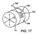
ここで、頸動脈14のような脈管の壁に取り付けられて、歪みゲージ、フォースゲージおよび/または圧力計を用いて壁の膨張または収縮を監視することができる、種々の変換器を示す、図17〜図19を参照されたい。血管の周りに配置することができる植え込み型血圧測定装置の一例は、Mieselらに付与された米国特許第6,106,477号に開示されており、その開示内容全体が参考として本明細書において援用される。そのような計測器からの出力は、例えば血圧および/または心拍数と相関させることができ、また本明細書において先に述べたように、制御システム60にフィードバックを提供するために用いることができる。図17では、植え込み型圧力測定用組立体は、総頸動脈14のような動脈の周りに配置される箔歪みゲージまたは力感知抵抗装置740を備えている。変換器部分742は、巻き付け、次いで縫合するかまたは他の方法で動脈14に取り付けたシリコーンの基部あるいは裏当て744に取り付けることができる。
Here, various transducers are shown that are attached to the wall of a vessel such as the
あるいは、図18に示すように、変換器750を、シアノアクリレートのような生物学的に適合する接着剤を用いて、動脈14の壁に接着接続してもよい。この実施形態では、変換器750は、力または圧力を測定するマイクロマシンセンサ(micro machined sensor)(MEMS)を備える。MEMS変換器750は、弾性の基部754の上に収容されたシリコーン製力センサに連結されたマイクロアーム752(図19に断面で示す)を備える。キャップ756が、基部754の最上部でアーム752を覆っている。基部754は、血管壁14からアーム752にわたって生成された内部開口部を含む。血管壁の膨張および収縮の際に力がアームに伝達されるように、非圧縮性ゲル756が、アーム752と血管壁14との間に充填されている。双方のケースで、動脈内の血圧の変化が血管壁の応力の変化を引き起こし、この変化が変換器によって検出され、それを血圧と相関させることができる。
Alternatively, as shown in FIG. 18, the
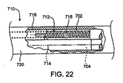
ここで、電極カフ装置またはより一般的には「電極組立体」と呼ぶこともできる、代替的血管外電気的活性化装置700を示す図20〜図22を参照されたい。本明細書に説明しかつ図に示すものを除き、装置700は、設計および機能において、前述の血管外電気的活性化装置300と同一であり得る。
Reference is now made to FIGS. 20-22 illustrating an alternative extravascular
図20および図21に見られるように、電極組立体またはカフ装置700は、可撓性の支持体706内に埋め込まれたコイル電極導体702/704を含む。図示した実施形態では、外側電極コイル702および内側電極コイル704は、疑似三極配置を提供するように用いられているが、前述の配置と同時に、他の極配置も適用が可能である。コイル電極702/704は、例えば、0.004インチのピッチで0.015インチの公称直径を有するコイル状に巻かれた0.002インチ直径の円形のPtIr合金のような、細い丸ワイヤ、平ワイヤまたは楕円ワイヤで形成することができる。可撓性の支持体または基部706は、例えば、0.005インチの壁厚および頸動脈洞を取り囲むのに十分な長さ(例えば2.95インチ)を有するシリコーンまたは他の適切な薄壁のエラストマー材料のような、生体適合性および可撓性(好ましくは弾性)の材料で形成することができる。
As seen in FIGS. 20 and 21, the electrode assembly or
電極702/704の接触領域内のコイルの各々の巻きは、動脈壁への導電路を形成するために、可撓性支持体706および任意の接着剤から露出されている。露出された電極702/704は、例えば、頸動脈洞の少なくとも一部の周りに伸びるのに十分な長さ(例えば0.236インチ)を有することができる。電極カフ700は、コイル電極702/704の接触面が可撓性支持体706の内側面に正接する状態で、平形に組み立てられる。電極カフ700が動脈の周りに巻き付けられる際に、コイル電極702/704の内側接触面は、必然的に、隣接する可撓性支持体表面のわずかに上方に伸ばされ、それにより動脈壁への接触が向上する。
Each turn of the coil in the contact area of
ワイヤ径に対するコイル電極702/704の直径の比は、ワイヤ内に有意な曲げ応力またはねじれ応力をかけることなくコイルを曲げかつ伸長することを可能にするのに十分な大きさを有することが好ましい。可撓性は、電極カフ700が頸動脈および洞の形状に適合することを可能にし、かつ顕著な応力または疲労に直面することなく動脈または洞の膨張および収縮を許容する、この設計の顕著な利点である。詳細には、可撓性電極カフ700は、移植時に、頸動脈洞および動脈の形状に適合するように巻き付けて伸ばすことができる。これは、電極カフ700のコンプライアンスにより、動脈および頸動脈洞の形状を崩壊または歪曲することなく達成することができる。可撓性支持体706は、カフ700の電極接触部分に繊維の補強材がないために、導電コイル702/704と共に撓みかつ伸びることができる。動脈の形状に適合することにより、また動脈壁に対して閉じている可撓性支持体706の縁部により、漂遊電界および外部からの刺激の量が減少する可能性がある。
The ratio of the diameter of the
コイル電極702/704のピッチは、ワイヤの各巻き間にスペースを設け、それにより必ずしもその軸方向伸長を必要とすることなく曲げることができるように、ワイヤ径よりも大きくすることができる。例えば、接触コイル702/704のピッチは、0.002インチ直径のワイヤについて一巻き当たり0.004インチとすることができ、それにより各巻きにおいてワイヤ間に0.002インチのスペースが可能となる。コイルの内側は、隣接するワイヤの巻き間のスペースを埋めることができるシリコーン接着剤のような可撓性の接着剤で充填することができる。隣接するコイルの巻き間の小スペースを埋めることにより、コイルの巻きの間に組織をはさむ可能性が最小限にされ、それにより動脈壁の擦傷が回避される。このようにして、埋め込まれたコイル電極702/704は、可撓性支持体706内に機械的に捕捉されかつ化学的に結合される。コイル電極702/704が支持体706から外れるという思いがけない事象においても、コイルの直径は、動脈壁を傷つけないように十分に大きい。コイル電極702/704の中心線は、電極カフ構造700の中立軸近傍に位置し、かつ可撓性支持体706は、コイル電極702/704と支持体706との間の接着結合部上にかかる剪断力を最小化するために、シリコーンのような等方的弾性を有する材料を含むことが好ましい。
The pitch of the
電極コイル702/704は、制御システム60に接続された細長いリード線710内で、対応する導電コイル712/714にそれぞれ接続されている。リード線710上に固定用ウィング718を設けてリード線710を隣接する組織につなぎ、リード線710と電極カフ700との間の影響または相対運動を最小化することができる。図22に見られるように、導電コイル712/714は、スプライスワイヤ716によって電極コイル702/704に電気的に接続された、巻いて0.018インチ径のコイルとした0.003 MP35Nのバイファイラーワイヤで形成することができる。導電コイル712/714は、シリコーンチューブのような絶縁被膜718で個別に被覆し、次に絶縁被膜720でひとまとめにして被覆することができる。
The electrode coils 702/704 are each connected to a corresponding
電極702/704の導電材料は、上述の金属またはPt粒子のような金属粒子を充填したシリコーン材料のような導電性高分子とすることができる。この後者の実施形態では、高分子電極は、可撓性支持体706の内側表面上に隆起した領域を備える電極端子をワイヤまたはワイヤコイルでリード線710に電気的に連結した状態で、可撓性支持体706と一体に形成してもよい。高分子電極の使用は、本明細書において他の箇所で説明した他の電極設計の実施形態にも適用することができる。
The conductive material of the
DACRON(登録商標)繊維のような補強パッチ708を、可撓性支持体706内に選択的に組み込んでもよい。例えば、縫合固定具を収容するために、可撓性支持体706の両端または他の領域に補強パッチ708を組み込むことができる。補強パッチ708は、電極カフ700を血管壁に縫合することができるポイントを提供し、かつ血管壁の外側に装置700をさらに固定するために、増殖中の組織をも提供することができる。例えば、繊維の補強パッチ708は、可撓性支持体706の縁部を越えて伸びることができ、これにより増殖中の組織によって電極組立体またはカフ700を血管壁に固定するのを支援することができ、かつ電極組立体700を所定の位置に保持するための縫合への依存度を低下させることができる。縫合および成長中の組織に代わるものまたはそれらに追加するものとして、装置700を血管壁に固定するのに、シアノアクリレートのような生体接着剤を用いることができる。さらに、Ptコーティングを施したマイクロ球体のような導電性粒子を混合した接着剤を電極702/704の露出した内側表面に塗布して、電気伝導を高めかつおそらくは1つの軸に沿って伝導を制限し、不要な組織刺激を制限することができる。
A reinforcing
補強パッチ708は、張力緩和目的で、またリード線710が電極組立体700に取り付けられている箇所および外側コイル702が内側コイル704の周りで折り返す箇所においてコイル702/704を支持体706に保持するのを支援するためにも、可撓性支持体706内に組み込むことができる。パッチ708は、特に電極702/704の領域において装置700の拡張および収縮を可能にするように、選択的に可撓性支持体706内に組み込まれるのが好ましい。詳細には、可撓性支持体706は、選択された領域においてのみ繊維によって補強され、それにより電極カフ700の伸長能力を保持している。
The reinforcing
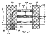
ここで図23〜図27を参照すると、図20〜図22の電極組立体は、電極が血管外組織に接触する上記組立体の領域において、「扁平な」コイル電極を有するように変更され得る。図23に示すように、電極組立体の電極担持面801は、通常、平行な補強ストリップまたは補強タブ808の間に配置される。扁平なコイル部分810は通常、基部806の下面803(図24)上で露出され、基部806の上面805上で、パリレンまたは他の高分子構造物または高分子材料802によって覆われるかもしくは封入されることになる。コイルは、図25および図27において最もよく分かるように、略円形の周縁部809を有して形成されており、図26において最もよく分かるように、一般にシリコーンまたは他の支持用挿入物815の上で機械的に扁平化することができる。扁平なコイル構造の使用は、それによって可撓性が保持され、電極がエラストマー基部806と共に曲がり、伸び、かつ撓むことが可能となり、同時に血管外表面に接触するために利用できる平坦な電極領域をも増大するので、特に有益である。
Referring now to FIGS. 23-27, the electrode assembly of FIGS. 20-22 can be modified to have a “flat” coil electrode in the region of the assembly where the electrode contacts extravascular tissue. . As shown in FIG. 23, the
ここで図28〜図31を参照し、本発明の原理に従って構築されたさらなる電極組立体900について説明する。電極組立体900は、電極基部、(代表的には、電極担持面904および該電極担持面から伸びる複数の取り付けタブ906(906a、906b、906c、および906d)を有する、一般にシリコーンまたは他のエラストマー材料で形成された、弾性の基部902を備える。取り付けタブ906は、基部902の電極担持面904と同じ材料で形成されるのが好ましいが、別のエラストマー材料で形成することもできる。後者の場合には、基部は、成形、引き伸ばしまたは別の方法で種々の部品から組み立てられる。図示した実施形態では、取り付けタブ906は、基部902の残部と一体に形成されている。すなわち、一般に、単一のエラストマー材料のシートから切り取られる。
With reference now to FIGS. 28-31, a
電極組立体900の形状、詳細には基部902の形状は、血管への多くの異なる取り付け方式を可能にするように選択されている。詳細には、図28の組立体902の形状は、頸動脈洞および頸動脈分岐部にあるかまたはそれらの近傍の、頸動脈上のさまざまな位置に取り付けることを可能にすることを目的としている。
The shape of the
相互に対するおよび/または基部902の電極担持面904に対する取り付けタブ906の縫合、クリッピング、ステープリング、もしくは他の固定を可能にするために、いくつかの補強領域910(910a、910b、910c、910d、および910e)が、基部902上のさまざまな位置に取り付けられている。頸動脈洞またはその周りでの取り付けを目的とする好ましい実施形態では、第1の補強ストリップ910aは、取り付けタブを担持する端部の反対側の基部902の端部上に備えられている。補強ストリップ910bの対および910cの対は、軸方向に整列している取り付けタブ906aならびに906bの各々の上に備えられ、さらに、同様の補強ストリップ910dの対および910eの対が、横方向に角度を付けた取り付けタブ906cならびに906dの各々の上に備えられている。図示した実施形態では、すべての取り付けタブが、好ましくは長方形の電極担持面904の隣接する隅から発し、基部の一面上に設けられることになる。
Several reinforced regions 910 (910a, 910b, 910c, 910d, 910d, 910a, 910b, 910d, 910d, 910a, 910b, 910d, And 910e) are attached at various locations on the
電極組立体900の構造により、電極920(上に詳細に説明したように伸縮性の扁平コイル電極が好ましい)が標的圧受容器に対して好ましい位置に配置されるように、外科医が電極組立体を移植することが可能となる。好ましい位置は、例えば、その全開示内容が参考として本明細書において援用される、2001年9月26日に出願された同時係属中の出願第09/963,991号に記載されているように決定することができる。
The structure of the
ひとたび電極組立体900の電極920のための好ましい位置が決定されれば、外科医は、電極920が下に位置する圧受容器に対して適切に配置されるように基部902の位置を合わせることができる。このようにして、電極920を、図29に示すように総頸動脈CCの上に配置してもよく、図30および図31に示すように、内頸動脈ICの上に配置してもよい。図29では、組立体900は、基部902ならびに取り付けタブ906aおよび906bを総頸動脈の外側上で伸ばすことによって取り付けることができる。次いで、補強タブ906aまたは906bを、縫合、ステープリング、固着、溶接、または他の周知の手段のいずれかによって補強ストリップ910aに固定することができる。通常、補強タブ906cおよび906dは、922ならびに924に示すように、それらの基部でそれぞれ切り取られることになる。
Once the preferred position for
別の例では、頸動脈洞の膨らみおよび圧受容器が頸動脈分岐部に対して異なる位置に存在する。例えば、図30に示すように、受容器が内頸動脈ICのさらに上方に位置し、このために、図29に示すような電極組立体900の配置が効果を現さないことがあり得る。しかしながら、組立体900は、なお、中央または軸方向のタブ906aおよび906bではなく横方向に角度を付けた取り付けタブ906cおよび906dを用いることにより、首尾よく取り付けることができる。図30に示すように、下方のタブ906dが総頸動脈CCに巻き付けられ、同時に上方の取り付けタブ906cが内頸動脈ICに巻き付けられている。軸方向の取り付けタブ906aおよび906bは通常切り取られる(位置926で)が、それらのうちのいずれかが、場合によっては内頸動脈ICに巻き付けられてもよい。この場合もまた、上に全体的に説明したように、使用するタブは、伸ばして補強ストリップ910aに取り付けることができる。
In another example, the carotid sinus bulge and baroreceptor are at different locations relative to the carotid bifurcation. For example, as shown in FIG. 30, the receptor may be located further above the internal carotid artery IC, so that the placement of the
図31を参照すると、頸動脈分岐部の角度が小さい場合、組立体900は、上の軸方向取り付けタブ906aおよび下の横方向に角度を付けた取り付けタブ906dを用いて取り付けることができる。取り付けタブ906bおよび906cは、位置928ならびに930に示すように、それぞれ切り取ることができる。すべての例において、基部902の弾力性および電極920の伸縮性により、頸動脈洞上での電極組立体の所望の適合性およびしっかりした取り付けが可能となる。これらの構造または類似の構造が脈管系の他の位置に電極構造を取り付けるのにも役立つことが分かるであろう。
Referring to FIG. 31, if the carotid bifurcation angle is small, the
本明細書において説明したほとんどの活性化装置実施形態において、その開示内容全体が参考として本明細書において援用される、Stokesに付与された米国特許第4,711,251号、Gatesに付与された米国特許第5,522,874号およびDi Domenicoらに付与された米国特許第4,972,848号に記載されているような抗炎症剤(例えばステロイド溶出電極)を組み込むことがおそらく望ましくあり得る。そのような薬剤は、装置(例えば電極)と血管壁組織との間の慢性的界面における組織の炎症を軽減し、それにより、例えば、刺激転送の効率を高め、電力消費量を減らし、かつ活性化の効率を保持する。 In most of the activation device embodiments described herein, U.S. Pat. No. 4,711,251 to Stokes, Gates, the entire disclosure of which is incorporated herein by reference. It may be desirable to incorporate anti-inflammatory agents (eg, steroid eluting electrodes) as described in US Pat. No. 5,522,874 and US Pat. No. 4,972,848 granted to Di Domenico et al. . Such agents reduce tissue inflammation at the chronic interface between the device (eg electrode) and vessel wall tissue, thereby increasing, for example, the efficiency of stimulus transfer, reducing power consumption, and active Keeping the efficiency of conversion.
上述の装置のいずれも、単独でもしくは他の適合性を有する装置と共に使用することができる。実際、いくつかの実施形態では、圧受容器活性化用の植え込み型装置を、関連する機能または全く異なる機能を実行する別の植え込み型装置と一体化させることができる。例えば、上述の圧反射活性化装置を両心室ペーシング装置、除細動器、電気的除細動器、薬物ポンプ、神経刺激器および/または同種のもののような植え込み型心臓ペースメーカと一体化させるのは好都合かもしれない。従って、圧反射活性化を提供するための種々の装置が任意の他の適切な植え込み型装置と共に使用するのに、またはその内部に組み込むのに適切であり得ることが、本発明の範囲内で企図される。 Any of the devices described above can be used alone or with other compatible devices. Indeed, in some embodiments, an implantable device for baroreceptor activation can be integrated with another implantable device that performs an associated function or a completely different function. For example, the baroreflex activation device described above may be integrated with an implantable cardiac pacemaker such as a biventricular pacing device, a defibrillator, a cardioverter defibrillator, a drug pump, a neurostimulator and / or the like. May be convenient. Accordingly, it is within the scope of the present invention that various devices for providing baroreflex activation may be suitable for use with or incorporated within any other suitable implantable device. Intended.
本発明は、本明細書において説明および企図された特定の実施形態以外の種々の形態で現すことができる。従って、添付の特許請求の範囲に記載した本発明の範囲および精神を逸脱することなく、形態ならびに詳細における脱却がなされ得る。 The present invention may be manifested in a variety of forms other than the specific embodiments described and contemplated herein. Accordingly, departures in form and detail may be made without departing from the scope and spirit of the invention as set forth in the appended claims.
Claims (41)
該患者の外部の位置から、該患者に対して、少なくとも第1の圧反射活性化刺激を付与する工程;
該患者の少なくとも1つの生理学的パラメータを測定する工程;および
該生理学的パラメータ測定値から、どの程度の該第1の圧反射活性化刺激が、該患者において圧反射反応を引き起こしたかを判定する工程、
を包含する、方法。 A method for testing a response to baroreflex activation in a patient, the method comprising:
Applying at least a first baroreflex activation stimulus to the patient from a location external to the patient;
Measuring at least one physiological parameter of the patient; and determining from the physiological parameter measurement how much of the first baroreflex activation stimulus caused a baroreflex response in the patient. ,
Including the method.
第2の圧反射活性化刺激を、前記患者の外部の位置から該患者に付与する工程であって、該第2の刺激は、少なくとも1つの、前記第1の刺激と異なる特性を有する、工程;
該患者の少なくとも1つの生理学的パラメータを測定する工程;および
前記生理学的パラメータ測定値から、どの程度の該第2の圧反射活性化刺激が、該患者において圧反射反応を引き起こしたかを判定する工程、
をさらに包含する、方法。 The method of claim 1, comprising:
Applying a second baroreflex activating stimulus to the patient from a location external to the patient, the second stimulus having at least one characteristic different from the first stimulus. ;
Measuring at least one physiological parameter of the patient; and determining from the physiological parameter measurement how much of the second baroreflex activation stimulus caused a baroreflex response in the patient. ,
Further comprising a method.
少なくとも1つの異なる特性を有する圧反射活性化刺激を毎回付与しながら、前記付与する工程、測定する工程および判定する工程を複数回反復する工程;ならびに
異なる圧反射刺激が異なる圧反射反応を引き起こす程度を記述するデータを生成する工程、
をさらに包含する、方法。 20. The method according to claim 19, comprising
Repeating each of the applying, measuring and determining steps multiple times while applying a baroreflex activating stimulus having at least one different characteristic each time; and the extent to which different baroreflex stimuli cause different baroreflex responses Generating data describing
Further comprising a method.
該患者の外部の位置から、該患者に対して、少なくとも1つの圧反射活性化刺激を付与するための、少なくとも1つの外部圧反射活性化装置と、
該患者の生理学的パラメータを測定し、該付与された刺激がどの程度まで該患者において圧反射活性化を引き起こしたかを判定するための、少なくとも1つの生理学的パラメータ測定装置と、
を備えるシステム。 A system for testing a response to baroreflex activation in a patient comprising:
At least one external baroreflex activation device for applying at least one baroreflex activation stimulus to the patient from a location external to the patient;
At least one physiological parameter measurement device for measuring physiological parameters of the patient and determining to what extent the applied stimulus caused baroreflex activation in the patient;
A system comprising:
Applications Claiming Priority (2)
| Application Number | Priority Date | Filing Date | Title |
|---|---|---|---|
| US54976004P | 2004-03-02 | 2004-03-02 | |
| PCT/US2005/007237 WO2005084389A2 (en) | 2004-03-02 | 2005-03-02 | External baroreflex activation |
Publications (2)
| Publication Number | Publication Date |
|---|---|
| JP2007526817A true JP2007526817A (en) | 2007-09-20 |
| JP2007526817A5 JP2007526817A5 (en) | 2009-02-26 |
Family
ID=34919535
Family Applications (1)
| Application Number | Title | Priority Date | Filing Date |
|---|---|---|---|
| JP2007502055A Pending JP2007526817A (en) | 2004-03-02 | 2005-03-02 | Activation of baroreflex from outside |
Country Status (4)
| Country | Link |
|---|---|
| US (1) | US7499747B2 (en) |
| EP (1) | EP1742700A4 (en) |
| JP (1) | JP2007526817A (en) |
| WO (1) | WO2005084389A2 (en) |
Families Citing this family (142)
| Publication number | Priority date | Publication date | Assignee | Title |
|---|---|---|---|---|
| US6616624B1 (en) * | 2000-10-30 | 2003-09-09 | Cvrx, Inc. | Systems and method for controlling renovascular perfusion |
| US6978174B2 (en) | 2002-04-08 | 2005-12-20 | Ardian, Inc. | Methods and devices for renal nerve blocking |
| US8145316B2 (en) | 2002-04-08 | 2012-03-27 | Ardian, Inc. | Methods and apparatus for renal neuromodulation |
| US7853333B2 (en) | 2002-04-08 | 2010-12-14 | Ardian, Inc. | Methods and apparatus for multi-vessel renal neuromodulation |
| US20070135875A1 (en) | 2002-04-08 | 2007-06-14 | Ardian, Inc. | Methods and apparatus for thermally-induced renal neuromodulation |
| US7162303B2 (en) | 2002-04-08 | 2007-01-09 | Ardian, Inc. | Renal nerve stimulation method and apparatus for treatment of patients |
| US8774913B2 (en) | 2002-04-08 | 2014-07-08 | Medtronic Ardian Luxembourg S.A.R.L. | Methods and apparatus for intravasculary-induced neuromodulation |
| US7653438B2 (en) | 2002-04-08 | 2010-01-26 | Ardian, Inc. | Methods and apparatus for renal neuromodulation |
| US8347891B2 (en) | 2002-04-08 | 2013-01-08 | Medtronic Ardian Luxembourg S.A.R.L. | Methods and apparatus for performing a non-continuous circumferential treatment of a body lumen |
| US8150520B2 (en) | 2002-04-08 | 2012-04-03 | Ardian, Inc. | Methods for catheter-based renal denervation |
| US9308043B2 (en) | 2002-04-08 | 2016-04-12 | Medtronic Ardian Luxembourg S.A.R.L. | Methods for monopolar renal neuromodulation |
| US9308044B2 (en) | 2002-04-08 | 2016-04-12 | Medtronic Ardian Luxembourg S.A.R.L. | Methods for therapeutic renal neuromodulation |
| US7620451B2 (en) | 2005-12-29 | 2009-11-17 | Ardian, Inc. | Methods and apparatus for pulsed electric field neuromodulation via an intra-to-extravascular approach |
| US7756583B2 (en) | 2002-04-08 | 2010-07-13 | Ardian, Inc. | Methods and apparatus for intravascularly-induced neuromodulation |
| US20140018880A1 (en) | 2002-04-08 | 2014-01-16 | Medtronic Ardian Luxembourg S.A.R.L. | Methods for monopolar renal neuromodulation |
| US8150519B2 (en) | 2002-04-08 | 2012-04-03 | Ardian, Inc. | Methods and apparatus for bilateral renal neuromodulation |
| US8131371B2 (en) | 2002-04-08 | 2012-03-06 | Ardian, Inc. | Methods and apparatus for monopolar renal neuromodulation |
| US8774922B2 (en) | 2002-04-08 | 2014-07-08 | Medtronic Ardian Luxembourg S.A.R.L. | Catheter apparatuses having expandable balloons for renal neuromodulation and associated systems and methods |
| US7617005B2 (en) | 2002-04-08 | 2009-11-10 | Ardian, Inc. | Methods and apparatus for thermally-induced renal neuromodulation |
| US20080213331A1 (en) | 2002-04-08 | 2008-09-04 | Ardian, Inc. | Methods and devices for renal nerve blocking |
| US9636174B2 (en) | 2002-04-08 | 2017-05-02 | Medtronic Ardian Luxembourg S.A.R.L. | Methods for therapeutic renal neuromodulation |
| US20070129761A1 (en) | 2002-04-08 | 2007-06-07 | Ardian, Inc. | Methods for treating heart arrhythmia |
| US8145317B2 (en) | 2002-04-08 | 2012-03-27 | Ardian, Inc. | Methods for renal neuromodulation |
| US7937143B2 (en) | 2004-11-02 | 2011-05-03 | Ardian, Inc. | Methods and apparatus for inducing controlled renal neuromodulation |
| FR2877205A1 (en) * | 2004-11-03 | 2006-05-05 | Luc Quintin | METHOD AND DEVICE FOR PREDICTING ABNORMAL MEDICAL EVENTS AND / OR ASSISTING DIAGNOSIS AND / OR MONITORING, ESPECIALLY FOR DETERMINING THE DEPTH OF ANESTHESIA |
| JP2006280485A (en) * | 2005-03-09 | 2006-10-19 | Motoharu Hasegawa | Blood pressure detecting device, blood pressure detecting method, blood pressure detecting program, and strain sensor for blood pressure detection |
| DE102005031116B4 (en) * | 2005-07-04 | 2012-04-12 | Siemens Ag | Shockwave system |
| US9642726B2 (en) | 2005-07-25 | 2017-05-09 | Vascular Dynamics, Inc. | Devices and methods for control of blood pressure |
| JP2009502302A (en) | 2005-07-25 | 2009-01-29 | グロス,ヨシ | Electrical stimulation of blood vessels |
| US8923972B2 (en) | 2005-07-25 | 2014-12-30 | Vascular Dynamics, Inc. | Elliptical element for blood pressure reduction |
| US9125732B2 (en) | 2005-07-25 | 2015-09-08 | Vascular Dynamics, Inc. | Devices and methods for control of blood pressure |
| US9592136B2 (en) | 2005-07-25 | 2017-03-14 | Vascular Dynamics, Inc. | Devices and methods for control of blood pressure |
| US8874227B2 (en) | 2009-03-20 | 2014-10-28 | ElectroCore, LLC | Devices and methods for non-invasive capacitive electrical stimulation and their use for vagus nerve stimulation on the neck of a patient |
| US8874205B2 (en) * | 2009-03-20 | 2014-10-28 | ElectroCore, LLC | Device and methods for non-invasive electrical stimulation and their use for vagal nerve stimulation |
| US8676330B2 (en) * | 2009-03-20 | 2014-03-18 | ElectroCore, LLC | Electrical and magnetic stimulators used to treat migraine/sinus headache and comorbid disorders |
| US20070232966A1 (en) * | 2005-11-30 | 2007-10-04 | Robert Applebaum | Apparatus for skin and muscle treatment |
| US20080009916A1 (en) * | 2006-05-19 | 2008-01-10 | Cvrx, Inc. | Applications of heart rate variability analysis in electrotherapy affecting autonomic nervous system response |
| EP2029194A2 (en) * | 2006-05-19 | 2009-03-04 | CVRX, Inc. | Characterization and modulation of physiologic response using baroreflex activation in conjunction with drug therapy |
| AU2007284033B2 (en) * | 2006-08-14 | 2012-02-02 | Med-El Elektro-Medizinische Gerate Gesellschaft M.B.H. | Implantable medical cuff with electrode array |
| US7797041B2 (en) * | 2006-10-11 | 2010-09-14 | Cardiac Pacemakers, Inc. | Transcutaneous neurostimulator for modulating cardiovascular function |
| US7797046B2 (en) * | 2006-10-11 | 2010-09-14 | Cardiac Pacemakers, Inc. | Percutaneous neurostimulator for modulating cardiovascular function |
| US20080288017A1 (en) * | 2007-02-27 | 2008-11-20 | Cvrx, Inc. | External Baroreflex Activation |
| US20080234779A1 (en) * | 2007-03-20 | 2008-09-25 | Cvrx, Inc. | Minimally invasive intraoperative modulation of patient parameters using baroreflex activation |
| US8828068B2 (en) | 2007-07-17 | 2014-09-09 | Cardiac Pacemakers, Inc. | Systems and methods for local vasoactive response using temperature modulation |
| US8594794B2 (en) | 2007-07-24 | 2013-11-26 | Cvrx, Inc. | Baroreflex activation therapy with incrementally changing intensity |
| WO2009018394A1 (en) * | 2007-07-31 | 2009-02-05 | Schneider M Bret | Device and method for hypertension treatment by non-invasive stimulation to vascular baroreceptors |
| WO2009021535A1 (en) * | 2007-08-14 | 2009-02-19 | Campus Micro Technologies Gmbh | Medical devices, systems and methods for blood pressure regulation |
| US20090093729A1 (en) * | 2007-10-03 | 2009-04-09 | Yunlong Zhang | Devices and Methods for Measurement of Vessel Elasticity and Blood Pressure |
| WO2009086536A1 (en) * | 2007-12-28 | 2009-07-09 | Cvrx, Inc. | Measurement of patient physiological parameters |
| US8214050B2 (en) | 2007-12-31 | 2012-07-03 | Cvrx, Inc. | Method for monitoring physiological cycles of a patient to optimize patient therapy |
| US8538535B2 (en) | 2010-08-05 | 2013-09-17 | Rainbow Medical Ltd. | Enhancing perfusion by contraction |
| US9005106B2 (en) | 2008-01-31 | 2015-04-14 | Enopace Biomedical Ltd | Intra-aortic electrical counterpulsation |
| US8626290B2 (en) | 2008-01-31 | 2014-01-07 | Enopace Biomedical Ltd. | Acute myocardial infarction treatment by electrical stimulation of the thoracic aorta |
| US8626299B2 (en) | 2008-01-31 | 2014-01-07 | Enopace Biomedical Ltd. | Thoracic aorta and vagus nerve stimulation |
| US8326430B2 (en) * | 2008-06-16 | 2012-12-04 | Cvrx, Inc. | Devices and methods for treatment of heart failure and associated conditions |
| US8321024B2 (en) | 2008-06-16 | 2012-11-27 | Cvrx, Inc. | Devices and methods for treatment of heart failure and associated conditions |
| US8401652B2 (en) | 2008-06-16 | 2013-03-19 | Cvrx, Inc. | Devices and methods for treatment of heart failure and associated conditions |
| ES2725524T3 (en) | 2008-09-26 | 2019-09-24 | Vascular Dynamics Inc | Devices and methods to control blood pressure |
| US8652129B2 (en) | 2008-12-31 | 2014-02-18 | Medtronic Ardian Luxembourg S.A.R.L. | Apparatus, systems, and methods for achieving intravascular, thermally-induced renal neuromodulation |
| US8224449B2 (en) * | 2009-06-29 | 2012-07-17 | Boston Scientific Neuromodulation Corporation | Microstimulator with flap electrodes |
| US20160059044A1 (en) | 2009-10-12 | 2016-03-03 | Kona Medical, Inc. | Energy delivery to intraparenchymal regions of the kidney to treat hypertension |
| US20110118600A1 (en) | 2009-11-16 | 2011-05-19 | Michael Gertner | External Autonomic Modulation |
| US9119951B2 (en) | 2009-10-12 | 2015-09-01 | Kona Medical, Inc. | Energetic modulation of nerves |
| US8469904B2 (en) | 2009-10-12 | 2013-06-25 | Kona Medical, Inc. | Energetic modulation of nerves |
| US8295912B2 (en) | 2009-10-12 | 2012-10-23 | Kona Medical, Inc. | Method and system to inhibit a function of a nerve traveling with an artery |
| US9174065B2 (en) | 2009-10-12 | 2015-11-03 | Kona Medical, Inc. | Energetic modulation of nerves |
| US8888699B2 (en) | 2010-04-29 | 2014-11-18 | Medtronic, Inc. | Therapy using perturbation and effect of physiological systems |
| US8620425B2 (en) | 2010-04-29 | 2013-12-31 | Medtronic, Inc. | Nerve signal differentiation in cardiac therapy |
| US8639327B2 (en) | 2010-04-29 | 2014-01-28 | Medtronic, Inc. | Nerve signal differentiation in cardiac therapy |
| US9066720B2 (en) | 2010-10-25 | 2015-06-30 | Medtronic Ardian Luxembourg S.A.R.L. | Devices, systems and methods for evaluation and feedback of neuromodulation treatment |
| US8437867B2 (en) | 2010-10-29 | 2013-05-07 | Cvrx, Inc. | Implant tool and improved electrode design for minimally invasive procedure |
| US8649863B2 (en) | 2010-12-20 | 2014-02-11 | Rainbow Medical Ltd. | Pacemaker with no production |
| US8725259B2 (en) | 2011-01-19 | 2014-05-13 | Medtronic, Inc. | Vagal stimulation |
| US8706223B2 (en) | 2011-01-19 | 2014-04-22 | Medtronic, Inc. | Preventative vagal stimulation |
| US8718763B2 (en) | 2011-01-19 | 2014-05-06 | Medtronic, Inc. | Vagal stimulation |
| US8781582B2 (en) | 2011-01-19 | 2014-07-15 | Medtronic, Inc. | Vagal stimulation |
| US8781583B2 (en) | 2011-01-19 | 2014-07-15 | Medtronic, Inc. | Vagal stimulation |
| US8721557B2 (en) | 2011-02-18 | 2014-05-13 | Covidien Lp | Pattern of cuff inflation and deflation for non-invasive blood pressure measurement |
| US9072433B2 (en) | 2011-02-18 | 2015-07-07 | Covidien Lp | Method and apparatus for noninvasive blood pressure measurement using pulse oximetry |
| US9199082B1 (en) | 2011-07-27 | 2015-12-01 | Cvrx, Inc. | Devices and methods for improved placement of implantable medical devices |
| US8855783B2 (en) | 2011-09-09 | 2014-10-07 | Enopace Biomedical Ltd. | Detector-based arterial stimulation |
| WO2013035092A2 (en) | 2011-09-09 | 2013-03-14 | Enopace Biomedical Ltd. | Wireless endovascular stent-based electrodes |
| WO2013059658A1 (en) | 2011-10-19 | 2013-04-25 | Sympara Medical Inc. | Methods and devices for treating hypertension |
| US8577458B1 (en) | 2011-12-07 | 2013-11-05 | Cyberonics, Inc. | Implantable device for providing electrical stimulation of cervical vagus nerves for treatment of chronic cardiac dysfunction with leadless heart rate monitoring |
| US10188856B1 (en) | 2011-12-07 | 2019-01-29 | Cyberonics, Inc. | Implantable device for providing electrical stimulation of cervical vagus nerves for treatment of chronic cardiac dysfunction |
| US8918190B2 (en) | 2011-12-07 | 2014-12-23 | Cyberonics, Inc. | Implantable device for evaluating autonomic cardiovascular drive in a patient suffering from chronic cardiac dysfunction |
| US8600505B2 (en) | 2011-12-07 | 2013-12-03 | Cyberonics, Inc. | Implantable device for facilitating control of electrical stimulation of cervical vagus nerves for treatment of chronic cardiac dysfunction |
| US8918191B2 (en) | 2011-12-07 | 2014-12-23 | Cyberonics, Inc. | Implantable device for providing electrical stimulation of cervical vagus nerves for treatment of chronic cardiac dysfunction with bounded titration |
| US8630709B2 (en) | 2011-12-07 | 2014-01-14 | Cyberonics, Inc. | Computer-implemented system and method for selecting therapy profiles of electrical stimulation of cervical vagus nerves for treatment of chronic cardiac dysfunction |
| US8700150B2 (en) | 2012-01-17 | 2014-04-15 | Cyberonics, Inc. | Implantable neurostimulator for providing electrical stimulation of cervical vagus nerves for treatment of chronic cardiac dysfunction with bounded titration |
| US8571654B2 (en) | 2012-01-17 | 2013-10-29 | Cyberonics, Inc. | Vagus nerve neurostimulator with multiple patient-selectable modes for treating chronic cardiac dysfunction |
| US9386991B2 (en) | 2012-02-02 | 2016-07-12 | Rainbow Medical Ltd. | Pressure-enhanced blood flow treatment |
| US9750568B2 (en) | 2012-03-08 | 2017-09-05 | Medtronic Ardian Luxembourg S.A.R.L. | Ovarian neuromodulation and associated systems and methods |
| EP3348220A1 (en) | 2012-03-08 | 2018-07-18 | Medtronic Ardian Luxembourg S.à.r.l. | Biomarker sampling in the context of neuromodulation devices and associated systems |
| US8688212B2 (en) | 2012-07-20 | 2014-04-01 | Cyberonics, Inc. | Implantable neurostimulator-implemented method for managing bradycardia through vagus nerve stimulation |
| US20140110296A1 (en) | 2012-10-19 | 2014-04-24 | Medtronic Ardian Luxembourg S.A.R.L. | Packaging for Catheter Treatment Devices and Associated Devices, Systems, and Methods |
| EP2914192B1 (en) | 2012-11-05 | 2019-05-01 | Pythagoras Medical Ltd. | Controlled tissue ablation |
| US9770593B2 (en) | 2012-11-05 | 2017-09-26 | Pythagoras Medical Ltd. | Patient selection using a transluminally-applied electric current |
| US9452290B2 (en) | 2012-11-09 | 2016-09-27 | Cyberonics, Inc. | Implantable neurostimulator-implemented method for managing tachyarrhythmia through vagus nerve stimulation |
| US9643008B2 (en) | 2012-11-09 | 2017-05-09 | Cyberonics, Inc. | Implantable neurostimulator-implemented method for enhancing post-exercise recovery through vagus nerve stimulation |
| US8923964B2 (en) | 2012-11-09 | 2014-12-30 | Cyberonics, Inc. | Implantable neurostimulator-implemented method for enhancing heart failure patient awakening through vagus nerve stimulation |
| AU2014207265B2 (en) | 2013-01-21 | 2017-04-20 | Cala Health, Inc. | Devices and methods for controlling tremor |
| US10076384B2 (en) | 2013-03-08 | 2018-09-18 | Symple Surgical, Inc. | Balloon catheter apparatus with microwave emitter |
| US9643011B2 (en) | 2013-03-14 | 2017-05-09 | Cyberonics, Inc. | Implantable neurostimulator-implemented method for managing tachyarrhythmic risk during sleep through vagus nerve stimulation |
| US9345877B2 (en) | 2013-08-05 | 2016-05-24 | Cvrx, Inc. | Adapter for connection to pulse generator |
| US9999773B2 (en) | 2013-10-30 | 2018-06-19 | Cyberonics, Inc. | Implantable neurostimulator-implemented method utilizing multi-modal stimulation parameters |
| CN108836586B (en) | 2013-11-06 | 2021-04-06 | 伊诺佩斯生医有限公司 | Wireless intravascular stent-based electrode |
| US9511228B2 (en) | 2014-01-14 | 2016-12-06 | Cyberonics, Inc. | Implantable neurostimulator-implemented method for managing hypertension through renal denervation and vagus nerve stimulation |
| US20170056682A1 (en) | 2014-02-24 | 2017-03-02 | Element Science, Inc. | External defibrillator |
| US9272143B2 (en) | 2014-05-07 | 2016-03-01 | Cyberonics, Inc. | Responsive neurostimulation for the treatment of chronic cardiac dysfunction |
| US9950169B2 (en) | 2014-04-25 | 2018-04-24 | Cyberonics, Inc. | Dynamic stimulation adjustment for identification of a neural fulcrum |
| US9409024B2 (en) | 2014-03-25 | 2016-08-09 | Cyberonics, Inc. | Neurostimulation in a neural fulcrum zone for the treatment of chronic cardiac dysfunction |
| US9713719B2 (en) | 2014-04-17 | 2017-07-25 | Cyberonics, Inc. | Fine resolution identification of a neural fulcrum for the treatment of chronic cardiac dysfunction |
| US9415224B2 (en) | 2014-04-25 | 2016-08-16 | Cyberonics, Inc. | Neurostimulation and recording of physiological response for the treatment of chronic cardiac dysfunction |
| US10194979B1 (en) | 2014-03-28 | 2019-02-05 | Medtronic Ardian Luxembourg S.A.R.L. | Methods for catheter-based renal neuromodulation |
| US10194980B1 (en) | 2014-03-28 | 2019-02-05 | Medtronic Ardian Luxembourg S.A.R.L. | Methods for catheter-based renal neuromodulation |
| US9980766B1 (en) | 2014-03-28 | 2018-05-29 | Medtronic Ardian Luxembourg S.A.R.L. | Methods and systems for renal neuromodulation |
| US10478249B2 (en) | 2014-05-07 | 2019-11-19 | Pythagoras Medical Ltd. | Controlled tissue ablation techniques |
| CN106413805A (en) | 2014-06-02 | 2017-02-15 | 卡拉健康公司 | Systems and methods for peripheral nerve stimulation to treat tremor |
| US9737716B2 (en) | 2014-08-12 | 2017-08-22 | Cyberonics, Inc. | Vagus nerve and carotid baroreceptor stimulation system |
| US9770599B2 (en) | 2014-08-12 | 2017-09-26 | Cyberonics, Inc. | Vagus nerve stimulation and subcutaneous defibrillation system |
| US9533153B2 (en) | 2014-08-12 | 2017-01-03 | Cyberonics, Inc. | Neurostimulation titration process |
| US10925579B2 (en) | 2014-11-05 | 2021-02-23 | Otsuka Medical Devices Co., Ltd. | Systems and methods for real-time tracking of a target tissue using imaging before and during therapy delivery |
| US9504832B2 (en) | 2014-11-12 | 2016-11-29 | Cyberonics, Inc. | Neurostimulation titration process via adaptive parametric modification |
| DE102014018683B4 (en) * | 2014-12-18 | 2017-11-02 | miha bodytec GmbH | EMS stimulus current transmitting element, as well as EMS garment equipped with the EMS stimulus current transmitting element |
| US20160235329A1 (en) * | 2015-02-13 | 2016-08-18 | The Charles Stark Draper Laboratory, Inc. | Nerve bundle cuff including electrodes and transducers |
| US10383685B2 (en) | 2015-05-07 | 2019-08-20 | Pythagoras Medical Ltd. | Techniques for use with nerve tissue |
| CN112914514A (en) | 2015-06-10 | 2021-06-08 | 卡拉健康公司 | System and method for peripheral nerve stimulation to treat tremor with a detachable treatment and monitoring unit |
| US10953234B2 (en) | 2015-08-26 | 2021-03-23 | Element Science, Inc. | Wearable devices |
| CN108348746B (en) | 2015-09-23 | 2021-10-12 | 卡拉健康公司 | System and method for peripheral nerve stimulation in fingers or hands to treat hand tremor |
| IL286747B1 (en) | 2016-01-21 | 2024-01-01 | Cala Health Inc | Wearable device for treating urinary symptoms |
| EP3457975A2 (en) | 2016-05-18 | 2019-03-27 | Pythagoras Medical Ltd. | Helical catheter |
| WO2018009680A1 (en) | 2016-07-08 | 2018-01-11 | Cala Health, Inc. | Systems and methods for stimulating n nerves with exactly n electrodes and improved dry electrodes |
| US10653513B2 (en) | 2017-02-21 | 2020-05-19 | Vascular Dynamics, Inc. | Baroreceptor testing prior to implantation methods and apparatus |
| CN110809486A (en) | 2017-04-03 | 2020-02-18 | 卡拉健康公司 | Peripheral neuromodulation systems, methods, and devices for treating diseases associated with overactive bladder |
| US11857778B2 (en) | 2018-01-17 | 2024-01-02 | Cala Health, Inc. | Systems and methods for treating inflammatory bowel disease through peripheral nerve stimulation |
| EP3863511A4 (en) | 2018-10-10 | 2022-04-06 | Element Science, Inc. | Wearable medical device with disposable and reusable components |
| US11890468B1 (en) | 2019-10-03 | 2024-02-06 | Cala Health, Inc. | Neurostimulation systems with event pattern detection and classification |
| CN111870810A (en) * | 2020-07-08 | 2020-11-03 | 武汉大学 | Carotid sinus baroreceptor stimulation device |
| US11400299B1 (en) | 2021-09-14 | 2022-08-02 | Rainbow Medical Ltd. | Flexible antenna for stimulator |
| EP4205801A1 (en) | 2021-12-29 | 2023-07-05 | CVRx, Inc. | Devices and methods for baroreflex activation |
| US20230355170A1 (en) | 2022-05-03 | 2023-11-09 | Cvrx, Inc. | External baroreflex activation for assessment and treatment |
Family Cites Families (6)
| Publication number | Priority date | Publication date | Assignee | Title |
|---|---|---|---|---|
| US6073048A (en) * | 1995-11-17 | 2000-06-06 | Medtronic, Inc. | Baroreflex modulation with carotid sinus nerve stimulation for the treatment of heart failure |
| US5727558A (en) * | 1996-02-14 | 1998-03-17 | Hakki; A-Hamid | Noninvasive blood pressure monitor and control device |
| US6178352B1 (en) * | 1999-05-07 | 2001-01-23 | Woodside Biomedical, Inc. | Method of blood pressure moderation |
| US6371922B1 (en) * | 2000-04-07 | 2002-04-16 | Cardiac Pacemakers, Inc. | Method for measuring baroreflex sensitivity and therapy optimization in heart failure patients |
| US6522926B1 (en) * | 2000-09-27 | 2003-02-18 | Cvrx, Inc. | Devices and methods for cardiovascular reflex control |
| US6985774B2 (en) * | 2000-09-27 | 2006-01-10 | Cvrx, Inc. | Stimulus regimens for cardiovascular reflex control |
-
2005
- 2005-03-02 US US11/071,602 patent/US7499747B2/en active Active
- 2005-03-02 EP EP05724725A patent/EP1742700A4/en not_active Withdrawn
- 2005-03-02 JP JP2007502055A patent/JP2007526817A/en active Pending
- 2005-03-02 WO PCT/US2005/007237 patent/WO2005084389A2/en active Application Filing
Also Published As
| Publication number | Publication date |
|---|---|
| US20060293712A1 (en) | 2006-12-28 |
| WO2005084389A3 (en) | 2006-11-16 |
| WO2005084389A9 (en) | 2006-04-20 |
| US7499747B2 (en) | 2009-03-03 |
| EP1742700A2 (en) | 2007-01-17 |
| WO2005084389A2 (en) | 2005-09-15 |
| EP1742700A4 (en) | 2008-05-28 |
Similar Documents
| Publication | Publication Date | Title |
|---|---|---|
| US7499747B2 (en) | External baroreflex activation | |
| US20200114153A1 (en) | Electrode structures and methods for their use in cardiovascular reflex control | |
| EP1487535B1 (en) | Electrode structures for use in cardiovascular reflex control | |
| US20080177365A1 (en) | Method and apparatus for electronically switching electrode configuration | |
| US20080172101A1 (en) | Non-linear electrode array | |
| US20100249874A1 (en) | Baroreflex therapy for disordered breathing |
Legal Events
| Date | Code | Title | Description |
|---|---|---|---|
| A521 | Request for written amendment filed |
Free format text: JAPANESE INTERMEDIATE CODE: A523 Effective date: 20080225 |
|
| A621 | Written request for application examination |
Free format text: JAPANESE INTERMEDIATE CODE: A621 Effective date: 20080225 |
|
| A521 | Request for written amendment filed |
Free format text: JAPANESE INTERMEDIATE CODE: A523 Effective date: 20090108 |
|
| A871 | Explanation of circumstances concerning accelerated examination |
Free format text: JAPANESE INTERMEDIATE CODE: A871 Effective date: 20090108 |
|
| A975 | Report on accelerated examination |
Free format text: JAPANESE INTERMEDIATE CODE: A971005 Effective date: 20090121 |
|
| A131 | Notification of reasons for refusal |
Free format text: JAPANESE INTERMEDIATE CODE: A131 Effective date: 20090123 |
|
| A601 | Written request for extension of time |
Free format text: JAPANESE INTERMEDIATE CODE: A601 Effective date: 20090422 |
|
| A602 | Written permission of extension of time |
Free format text: JAPANESE INTERMEDIATE CODE: A602 Effective date: 20090430 |
|
| A601 | Written request for extension of time |
Free format text: JAPANESE INTERMEDIATE CODE: A601 Effective date: 20090522 |
|
| A602 | Written permission of extension of time |
Free format text: JAPANESE INTERMEDIATE CODE: A602 Effective date: 20090529 |
|
| A02 | Decision of refusal |
Free format text: JAPANESE INTERMEDIATE CODE: A02 Effective date: 20090812 |