JP2007525107A - Ring interface unit - Google Patents
Ring interface unit Download PDFInfo
- Publication number
- JP2007525107A JP2007525107A JP2006541631A JP2006541631A JP2007525107A JP 2007525107 A JP2007525107 A JP 2007525107A JP 2006541631 A JP2006541631 A JP 2006541631A JP 2006541631 A JP2006541631 A JP 2006541631A JP 2007525107 A JP2007525107 A JP 2007525107A
- Authority
- JP
- Japan
- Prior art keywords
- node
- ring
- slave
- interface unit
- data
- Prior art date
- Legal status (The legal status is an assumption and is not a legal conclusion. Google has not performed a legal analysis and makes no representation as to the accuracy of the status listed.)
- Withdrawn
Links
- 230000008878 coupling Effects 0.000 claims description 11
- 238000010168 coupling process Methods 0.000 claims description 11
- 238000005859 coupling reaction Methods 0.000 claims description 11
- 230000015654 memory Effects 0.000 description 37
- 238000012545 processing Methods 0.000 description 36
- 238000004891 communication Methods 0.000 description 31
- 238000010586 diagram Methods 0.000 description 24
- 230000005540 biological transmission Effects 0.000 description 19
- 238000000034 method Methods 0.000 description 12
- 230000006870 function Effects 0.000 description 9
- 230000009977 dual effect Effects 0.000 description 7
- 230000003750 conditioning effect Effects 0.000 description 6
- 230000008569 process Effects 0.000 description 5
- 238000012546 transfer Methods 0.000 description 5
- 230000005587 bubbling Effects 0.000 description 4
- 230000002457 bidirectional effect Effects 0.000 description 3
- 230000008901 benefit Effects 0.000 description 2
- 230000002950 deficient Effects 0.000 description 2
- 230000003068 static effect Effects 0.000 description 2
- RYGMFSIKBFXOCR-UHFFFAOYSA-N Copper Chemical compound [Cu] RYGMFSIKBFXOCR-UHFFFAOYSA-N 0.000 description 1
- 238000013459 approach Methods 0.000 description 1
- 238000003491 array Methods 0.000 description 1
- 239000003795 chemical substances by application Substances 0.000 description 1
- 239000002131 composite material Substances 0.000 description 1
- 238000004590 computer program Methods 0.000 description 1
- 229910052802 copper Inorganic materials 0.000 description 1
- 239000010949 copper Substances 0.000 description 1
- 230000006378 damage Effects 0.000 description 1
- 238000013500 data storage Methods 0.000 description 1
- 230000034994 death Effects 0.000 description 1
- 231100000517 death Toxicity 0.000 description 1
- 238000012986 modification Methods 0.000 description 1
- 230000004048 modification Effects 0.000 description 1
- 238000012544 monitoring process Methods 0.000 description 1
- 239000004065 semiconductor Substances 0.000 description 1
- 208000027765 speech disease Diseases 0.000 description 1
Images


Classifications
-
- H—ELECTRICITY
- H04—ELECTRIC COMMUNICATION TECHNIQUE
- H04L—TRANSMISSION OF DIGITAL INFORMATION, e.g. TELEGRAPHIC COMMUNICATION
- H04L12/00—Data switching networks
- H04L12/28—Data switching networks characterised by path configuration, e.g. LAN [Local Area Networks] or WAN [Wide Area Networks]
- H04L12/46—Interconnection of networks
- H04L12/4637—Interconnected ring systems
-
- H—ELECTRICITY
- H04—ELECTRIC COMMUNICATION TECHNIQUE
- H04L—TRANSMISSION OF DIGITAL INFORMATION, e.g. TELEGRAPHIC COMMUNICATION
- H04L12/00—Data switching networks
- H04L12/28—Data switching networks characterised by path configuration, e.g. LAN [Local Area Networks] or WAN [Wide Area Networks]
-
- H—ELECTRICITY
- H04—ELECTRIC COMMUNICATION TECHNIQUE
- H04L—TRANSMISSION OF DIGITAL INFORMATION, e.g. TELEGRAPHIC COMMUNICATION
- H04L12/00—Data switching networks
- H04L12/28—Data switching networks characterised by path configuration, e.g. LAN [Local Area Networks] or WAN [Wide Area Networks]
- H04L12/40—Bus networks
- H04L12/403—Bus networks with centralised control, e.g. polling
-
- H—ELECTRICITY
- H04—ELECTRIC COMMUNICATION TECHNIQUE
- H04L—TRANSMISSION OF DIGITAL INFORMATION, e.g. TELEGRAPHIC COMMUNICATION
- H04L12/00—Data switching networks
- H04L12/28—Data switching networks characterised by path configuration, e.g. LAN [Local Area Networks] or WAN [Wide Area Networks]
- H04L12/40—Bus networks
- H04L12/407—Bus networks with decentralised control
- H04L12/413—Bus networks with decentralised control with random access, e.g. carrier-sense multiple-access with collision detection (CSMA-CD)
- H04L12/4135—Bus networks with decentralised control with random access, e.g. carrier-sense multiple-access with collision detection (CSMA-CD) using bit-wise arbitration
-
- H—ELECTRICITY
- H04—ELECTRIC COMMUNICATION TECHNIQUE
- H04L—TRANSMISSION OF DIGITAL INFORMATION, e.g. TELEGRAPHIC COMMUNICATION
- H04L12/00—Data switching networks
- H04L12/28—Data switching networks characterised by path configuration, e.g. LAN [Local Area Networks] or WAN [Wide Area Networks]
- H04L12/42—Loop networks
- H04L12/427—Loop networks with decentralised control
- H04L12/43—Loop networks with decentralised control with synchronous transmission, e.g. time division multiplex [TDM], slotted rings
-
- H—ELECTRICITY
- H04—ELECTRIC COMMUNICATION TECHNIQUE
- H04L—TRANSMISSION OF DIGITAL INFORMATION, e.g. TELEGRAPHIC COMMUNICATION
- H04L12/00—Data switching networks
- H04L12/28—Data switching networks characterised by path configuration, e.g. LAN [Local Area Networks] or WAN [Wide Area Networks]
- H04L12/42—Loop networks
- H04L12/437—Ring fault isolation or reconfiguration
-
- H—ELECTRICITY
- H04—ELECTRIC COMMUNICATION TECHNIQUE
- H04L—TRANSMISSION OF DIGITAL INFORMATION, e.g. TELEGRAPHIC COMMUNICATION
- H04L12/00—Data switching networks
- H04L12/28—Data switching networks characterised by path configuration, e.g. LAN [Local Area Networks] or WAN [Wide Area Networks]
- H04L12/40—Bus networks
- H04L12/40169—Flexible bus arrangements
- H04L12/40176—Flexible bus arrangements involving redundancy
- H04L12/40189—Flexible bus arrangements involving redundancy by using a plurality of bus systems
-
- H—ELECTRICITY
- H04—ELECTRIC COMMUNICATION TECHNIQUE
- H04L—TRANSMISSION OF DIGITAL INFORMATION, e.g. TELEGRAPHIC COMMUNICATION
- H04L12/00—Data switching networks
- H04L12/28—Data switching networks characterised by path configuration, e.g. LAN [Local Area Networks] or WAN [Wide Area Networks]
- H04L12/40—Bus networks
- H04L2012/40267—Bus for use in transportation systems
- H04L2012/40273—Bus for use in transportation systems the transportation system being a vehicle
Abstract
一実施形態では、ネットワークが、複数のリニアバスノードおよび複数のリングインタフェースユニットを備える。リニアバスノードはそれぞれ、複数のリングインタフェースユニットの少なくとも1つを用いて、複数のリングそれぞれに通信可能に結合される。別の実施形態では、ネットワークが、リングおよび複数のノードを備える。複数のノードはそれぞれ、リニアバスを介してデータを通信するように適合される。ネットワークは、複数のリングインタフェースユニットをさらに備える。リングインタフェースユニットはそれぞれ、リングにそれぞれのノードを通信可能に結合する。 In one embodiment, the network comprises a plurality of linear bus nodes and a plurality of ring interface units. Each linear bus node is communicatively coupled to each of the plurality of rings using at least one of the plurality of ring interface units. In another embodiment, the network comprises a ring and a plurality of nodes. Each of the plurality of nodes is adapted to communicate data via a linear bus. The network further comprises a plurality of ring interface units. Each ring interface unit communicatively couples each node to the ring.
Description
本出願は、参照によって本明細書に組み込まれている、2003年11月19日に出願した米国仮出願第60/523839号に関連し、その出願日付の利益を主張する。
以下の説明は、概して通信システムに関し、詳細には、分散型耐故障システムに関する。
This application is related to and claims the benefit of US Provisional Application No. 60 / 523,839, filed Nov. 19, 2003, which is incorporated herein by reference.
The following description relates generally to communication systems and in particular to distributed fault tolerant systems.
故障の結果、1人または複数の負傷または死亡者が生じる可能性があるアプリケーションにおいて、分散型耐故障通信システムが通常、用いられる。このようなアプリケーションは、本明細書において、「安全性が重大なアプリケーション」と呼ばれる。安全性が重大なアプリケーションの一例は、飛行機または他の航空もしくは地上車両に含まれるセンサおよびアクチュエータを監視し管理するのに用いられるシステム内にある。 Distributed fault tolerant communication systems are typically used in applications where failure can result in one or more injuries or deaths. Such applications are referred to herein as “safety critical applications”. An example of a safety critical application is in a system used to monitor and manage sensors and actuators contained in airplanes or other aviation or ground vehicles.
航空および他の車両用アプリケーションにおいて、通常は、このような分散型耐故障システムの重量およびコストを最小限に抑えることが望ましい。伝統的な耐故障通信アーキテクチャ(たとえば、三重モジュール式冗長や四重冗長アーキテクチャ)は、このようなアーキテクチャにおいてもたらされる冗長な通信経路の追加コストおよび/または追加重量のせいで、個々のシャーシまたは機器部では対応できない程の、このような耐故障システムにおける重量およびコストに関わるかなりの不利益を被る。 In aviation and other vehicular applications, it is usually desirable to minimize the weight and cost of such distributed fault tolerant systems. Traditional fault-tolerant communication architectures (eg, triple modular redundancy or quadruple redundancy architectures) allow individual chassis or equipment components due to the additional cost and / or additional weight of redundant communication paths introduced in such architectures. Suffers considerable disadvantages related to the weight and cost of such a fault tolerant system that cannot be accommodated.
一般に、航空アプリケーションにおける使用に対して検討される1つのアーキテクチャは、時間駆動アーキテクチャ(TTA)である。TTAシステムにおいて、多数のノードが、たとえば時間駆動プロトコル/C(TTP/C)を用いて、2つの複製高速通信チャネルを介して相互に通信する。いくつかの実施形態では、このようなTTAシステム内のノードの少なくとも1つが、たとえば時間駆動プロトコル/A(TTP/A)を用いて、2つの複製低速直列通信チャネルを介して、1つまたは複数のセンサおよび/またはアクチュエータに結合される。TTA、TTP/C、およびTTP/Aは、TTTech Computertechnik AGによって推奨されている仕様に記載されている。 In general, one architecture that is considered for use in aviation applications is the time-driven architecture (TTA). In a TTA system, multiple nodes communicate with each other via two replicated high-speed communication channels using, for example, a time-driven protocol / C (TTP / C). In some embodiments, at least one of the nodes in such a TTA system may use one or more via two replicated low-speed serial communication channels, eg, using time-driven protocol / A (TTP / A). To the sensors and / or actuators. TTA, TTP / C, and TTP / A are described in the specifications recommended by TTTech Computertechnik AG.
通常、TTAシステムでは、多数のノードが、TTP/Cプロトコルに従って、スター型トポロジまたはバストポロジを有する通信ネットワークを用いてすべてネットワーク接続される。同様に、ノードならびにそのノードと通信するセンサおよび/またはアクチュエータが、TTP/Aプロトコルに従って、リニアバストポロジを用いてすべてネットワーク接続される。スター型トポロジ(ここでは、「スター型ネットワーク」とも呼ばれる)を有するネットワークは、多数の冗長なデータ経路をもたらすが、スター型ネットワークは通常、実装するのに大規模な、より多くの配線を必要とし、その結果、ノードの間の距離が増すと、このようなスター型ネットワークのコストおよび重量が増す。リニアバストポロジ(ここでは、「リニアバストポロジ」とも呼ばれる)を有するネットワークは通常、実装するのに、スター型ネットワークよりはるかに少ないワイヤを必要とする。ただし、リニアバスネットワークは、単一障害点の影響を受けやすいので、高い信頼性を必要とする、安全性が重大な一部のアプリケーションには適さない場合がある。 Typically, in a TTA system, a large number of nodes are all networked using a communication network having a star topology or a bus topology according to the TTP / C protocol. Similarly, the nodes and the sensors and / or actuators that communicate with the nodes are all networked using a linear bus topology according to the TTP / A protocol. A network with a star topology (also referred to here as a “star network”) provides a large number of redundant data paths, but a star network typically requires more wiring at scale to implement As a result, the cost and weight of such a star network increases as the distance between the nodes increases. A network with a linear bus topology (also referred to herein as a “linear bus topology”) typically requires much fewer wires to implement than a star network. However, linear bus networks are susceptible to single points of failure and may not be suitable for some safety critical applications that require high reliability.
一実施形態では、機器が、複数のリニアバスを介してデータを通信するように適合されたノードと、このノードと通信し、ノードを複数のリングに通信可能に結合するためのリングインタフェースユニットとを備える。 In one embodiment, a node adapted to communicate data over a plurality of linear buses and a ring interface unit for communicating with the node and communicatively coupling the node to a plurality of rings. Prepare.
別の実施形態では、機器が、リニアバスノードと、リニアバスノードを複数のリングに通信可能に結合するためのリングインタフェースユニットとを備える。
別の実施形態では、ネットワークが、複数のノードを備える。複数のノードはそれぞれ、複数のリニアバスを介してデータを通信するように適合される。ネットワークは、複数のリングインタフェースユニットをさらに備える。リングインタフェースユニットはそれぞれ、複数のリングにそれぞれのノードを通信可能に結合する。
In another embodiment, an apparatus comprises a linear bus node and a ring interface unit for communicatively coupling the linear bus node to a plurality of rings.
In another embodiment, the network comprises a plurality of nodes. Each of the plurality of nodes is adapted to communicate data via a plurality of linear buses. The network further comprises a plurality of ring interface units. Each ring interface unit communicatively couples each node to a plurality of rings.
別の実施形態では、ネットワークが、複数のリニアバスノードおよび複数のリングインタフェースユニットを備える。リニアバスノードはそれぞれ、複数のリングインタフェースユニットの少なくとも1つを用いて、複数のリングそれぞれに通信可能に結合される。 In another embodiment, the network comprises a plurality of linear bus nodes and a plurality of ring interface units. Each linear bus node is communicatively coupled to each of the plurality of rings using at least one of the plurality of ring interface units.
別の実施形態では、機器が、リニアバスを介してデータを通信するように適合されたノードと、このノードと通信し、ノードをリングに通信可能に結合するためのリングインタフェースユニットとを備える。 In another embodiment, an apparatus comprises a node adapted to communicate data via a linear bus and a ring interface unit for communicating with the node and communicatively coupling the node to a ring.
特許請求の範囲に記載されている本発明の1つまたは複数の実施形態の詳細が、添付の図面および以下の説明において説明される。こうした説明、図面、および特許請求の範囲から、他の特徴および利点が明らかになるであろう。 The details of one or more embodiments of the claimed invention are set forth in the accompanying drawings and the description below. Other features and advantages will be apparent from the description, drawings, and claims.
様々な図面における同じ参照番号および名称は、同じ要素を示す。 Like reference numbers and designations in the various drawings indicate like elements.
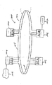
図1は、通信ネットワーク100の一実施形態の上位ブロック図である。ネットワーク100の実施形態は、安全性が重大なアプリケーションにおいて(たとえば、航空または自動車用アプリケーションにおいて)使われる分散型耐故障システムにおける、そのシステムとの、またはそのシステムとしての使用に適している。図1に示される実施形態において、ネットワーク100は、マスター/スレーブTTP/Aプロトコルアーキテクチャを用いて実装される。ネットワーク100は、1つのマスターノードペア102(ここでは、「マスターペア」102とも呼ばれる)および多数のスレーブノードペア104(ここでは、「スレーブペア」102とも呼ばれる)を含む。図1に示される実施形態では、ネットワーク100を介してマスターペア102と通信する3つのスレーブノードペア104(個別に「スレーブペアA」、「スレーブペアB」、および「スレーブペアC」で示す)がある。他の実施形態では、他の数のサブシステムが使われる。
FIG. 1 is a high-level block diagram of one embodiment of a
図1に示される実施形態において、各ノードペア102、104は、2つの冗長ノードを含む。他の実施形態では、ネットワーク100内のノードペア102および/または104の1つまたは複数によって実施される機能は、異なる数のノードを有して(たとえば、単一のノードまたは3つ以上のノードを使って)実装される。マスターペア102は、2つのマスターノード106を含む。マスターノード106はここでは、それぞれ、個別に「マスターノードA」および「マスターノードB」と呼ばれる。各マスターノード106は、マスターノード向けにTTP/A仕様において指定された通信および制御機能を実装する。一実装形態では、マスターノード106の1つは、1次マスターノードと指定され、そうすることが可能な場合は、ネットワーク100のためにマスターノード処理を実施する。このような実装において、他方のマスターノード106は、2次またはバックアップマスターノード106と指定される。1次マスターノードが、ネットワーク100のためにマスターノード処理を実施中(ここでは、「アクティブ」モードで動作中とも呼ばれる)の間、2次マスターノード106は、「シャドー」モードで動作し、このモードでは、2次マスターノード106は、ネットワーク100内の通信を監視し、そうすることによって、1次マスターノードがマスターノード処理を実施することが不可能になった場合には、2次マスターノード106が、ネットワーク100のためのマスターノード処理の実施を直ちに引き継ぐことが可能になる。他の実装形態では、他の二重冗長性方式が用いられる。
In the embodiment shown in FIG. 1, each
スレーブペア104はそれぞれ、2つのスレーブノード108を含む。各スレーブペア108のスレーブノード108はここでは、それぞれ個別に「スレーブノードA」および「スレーブノードB」と呼ばれる。各スレーブノード108は、スレーブトランスデューサノード向けにTTP/A仕様で指定された通信および制御機能を実装する。各スレーブペア104の各スレーブノードA、Bは、少なくとも1つのトランスデューサ110に結合される。少なくとも1つのトランスデューサ110は、たとえば、少なくとも1つのセンサおよび/またはアクチュエータを含む。図1に示される実施形態において、各スレーブペア104は、2つの冗長トランスデューサ110を含み、一方のトランスデューサ110(ここでは、「トランスデューサA」とも呼ばれる)は、スレーブノードAに結合され、もう一方のトランスデューサ110(ここでは、「トランスデューサBとも呼ばれる」)は、スレーブノードBに結合されている。マスターノードペア102(より具体的には、マスターノードA、B)は、センサ(トランスデューサ110はセンサを含む)によって検出された情報を受信するため、かつ/またはアクチュエータ(トランスデューサ110はアクチュエータを含む)を作動させるために、スレーブペア104(より具体的には、スレーブノードA、B)と通信する。このような実装において、マスターノードペア102とスレーブノードペア104の間のデータ通信(たとえば、フレームの形での通信)は、TTP/Aプロトコルに従って行われる。
Each
図1に示される実施形態の一実装形式では、各スレーブペア104に対して、スレーブノード108の1つが、1次スレーブノードと指定され、そうすることが可能な場合は、そのスレーブペア104のためにスレーブノード処理を実施する。このような実装において、各スレーブサブシステム104用の他のスレーブノードは、2次またはバックアップスレーブノードと指定される。1次スレーブノードが、所与のスレーブペア104のためにスレーブノード処理を実施中(ここでは、「アクティブ」モードで動作中とも呼ばれる)の間、2次スレーブノードは、「待機」モードで動作し、このモードでは、2次スレーブノードは、ネットワーク100内の通信を監視し、そうすることによって、1次スレーブノードがスレーブノード処理を実施することが不可能になった場合には、2次スレーブノードが、そのスレーブペア104のためのスレーブノード処理の実施を直ちに引き継ぐことが可能になる。他の実装形態では、他の二重冗長性方式が用いられる。
In one implementation of the embodiment shown in FIG. 1, for each
マスターペア102は、2つの通信チャネル112を介してスレーブサブシステム104と通信する。通信チャネル112はそれぞれ、各ノードを、そのノードの2つの隣接ノードに接続する多重双方向直列リンク114を含むリングとして実装される。2つのチャネル112はここでは、それぞれ、個別に「チャネル0」または「リング0」および「チャネル1」または「リング1」とも呼ばれる。たとえば、図1に示されるように、リング0の一部であるリンク114は、マスターノードAを、マスターノードBに時計回り方向に結合し、リング0の一部である別のリンク114は、マスターノードAを、スレーブペアCのスレーブノードAに反時計回り方向に結合する。2つのリングが図1に示されているが、他の実施形態では、より多くのまたはより少ないリングが使われる(たとえば、図11に示される実施形態では、1つのリングが使われる)ことが理解されるべきである。
図1に示される具体的な実施形態において、ノード106、108は、TTP/Aリニアバス構成要素を使って実装される。つまり、ノード106、108はそれぞれ、通常はTTP/Aノードを1つまたは複数のリニアバスに結合するのに使われるTTP/A構成要素を使って実装される。図1に示される具体的な実施形態において、各ノード106、108は、4つのリニアバスを介して通信するように適合される。各リニアバスノードは、1対のリングインタフェースユニット120を用いてリングに結合される。このような各リニアバスノードに対して、一方のリングインタフェースユニット120(ここでは、個別にリングインタフェースユニット120−0と呼ばれる)が、ノードをリング0に結合し、他方のリングインタフェースユニット(ここでは、個別にリングインタフェースユニット120−1と呼ばれる)が、ノードをリング1に結合する。このようにして、TTP/Aリニアバス構成要素は、図1の二重リングバストポロジにおいて使われ得る。より全般的には、リングインタフェースユニット120は、このようなリニアバス構成要素を利用して達成され得る完全性および/または信頼性を向上させるために、このようなトポロジにおける使用以外のためには設計されていないリニアバス構成要素を使って、リングバストポロジ(または同様のトポロジ)を実装するのに使われ得る。
In the specific embodiment shown in FIG. 1,
各リングインタフェースユニット120は、図1で、対応するノードとは別個のものとして示されているが、他の実施形態ではリングインタフェースユニット120は、対応するノードに統合される(たとえば、TTP/Aインタフェース構成要素が、ネットワーク100のリングバストポロジを直接サポートする場合)。また、他の実施形態では、本明細書において所与のリニアバスノード向けの1対のリングインタフェースユニット120−0、120−1によって実施されるものとして記載される機能は、単一のリングインタフェースユニットを用いて実装される。
Each
各マスターノード106は、第2の上位層ネットワーク116(図1に示される実施形態では、TTP/Cネットワーク116)へのゲートウェイとしても働く。マスターノード106は、ネットワーク116内のノード(図1には示さず)と、2つの複製高速チャネル118を介して通信する。たとえば、このような実施形態の一実装形式において、ネットワーク116は、バストポロジまたはスター型トポロジを用いて実装され、高速チャネル118は、イーサネット(登録商標)ネットワークプロトコルなどのローカルエリアネットワークプロトコルを用いて実装される。
Each
動作する際、図1に示されるネットワーク100の実施形態におけるノード106、108の1つ(ここでは、「送信ノード」と呼ばれる)が、ネットワーク100内の他のノードにデータを(たとえば、1つまたは複数のデータフレームの形で)送信する際、送信ノードは、4つの別々のデータ経路に沿って同じデータを送信する。TTP/Aプロトコルを用いて実装される、図1に示される具体的な実施形態において、ネットワーク100内のノードは、合意がとれている時分割多元接続(TDMA)スケジュールに従って送信する。送信ノードは、リング0の周囲を時計回りおよび反時計回り両方向で、かつリング1の周囲を時計回りおよび反時計回り両方向でデータを送信する。このような実施形態において、あるノードによる各送信に対して、ネットワーク内の他のノードの1つが、その送信用の「終端」または「宛先」ノードとして指定される。送信ノードおよび指定された終端ノードは、リング0、1を「切断する」。ネットワーク100内の他のノード(つまり、送信ノードおよび終端ノード以外のノード)はそれぞれ、リピータとして働き、そのノードによって受信されたどのデータも、ネットワーク100内の次のノードに、データが受信されたのと同じリングに沿って転送する。
In operation, one of the
一例では、マスターノードAが送信ノードであり、スレーブペアBのスレーブノードAが、その送信用の終了ノードである。このような例において、マスターノードAは、結合されているリングインタフェースユニット120−0を経由して、時計回りおよび反時計回り両方向でリング0に沿って送信し、リングインタフェースユニット120−1を経由して、時計回りおよび反時計回り両方向でリング1に沿って送信する。反時計回り方向でリング0に沿ってマスターノードAから送信されるデータは、スレーブペアCのスレーブノードAに結合されたリングインタフェースユニット120−0によって最初に受信され、このインタフェースユニットが、受信したデータを、リング0に沿って反時計回り方向でスレーブペアCのスレーブノードBに転送する。リングインタフェースユニット120−0は、受信したデータを、そうすることによってTTP/Aプロトコル処理のためにスレーブペアCのスレーブノードAにも転送する。スレーブペアCのスレーブノードBに結合されたリングインタフェースユニット120−0は、リング0からデータを受信し、受信したデータを、リング0に沿って反時計回り方向で、スレーブペアBのスレーブノードAに転送する。リングインタフェースユニット120−0は、受信したデータを、そうすることによってTTP/Aプロトコル処理のために、スレーブペアCのスレーブノードBにも転送する。スレーブペアBのスレーブノードAに結合されたリングインタフェースユニット120−0は、リング0からデータを受信する。スレーブペアBのスレーブノードAは、この例では終了ノードなので、そのノードに結合されたリングインタフェースユニット120−0は、受信したデータをそれ以上、リング0に沿って反時計回り方向で転送しない。スレーブペアBのスレーブノードAに結合されたリングインタフェースユニット120−0は、受信したデータを、そうすることによってTTP/Aプロトコル処理のためにスレーブペアBのスレーブノードAに転送する。
In one example, the master node A is a transmission node, and the slave node A of the slave pair B is an end node for transmission. In such an example, the master node A transmits along
同様の処理が、リング1に沿って反時計回り方向で起こる。反時計回り方向でリング1に沿ってマスターノードAから送信されるデータは、スレーブペアCのスレーブノードAに結合されたリングインタフェースユニット120−1によって最初に受信され、このインタフェースユニットが、受信したデータを、リング1に沿って反時計回り方向でスレーブペアCのスレーブノードBに転送する。リングインタフェースユニット120−1は、受信したデータを、そうすることによってTTP/Aプロトコル処理のためにスレーブペアCのスレーブノードAにも転送する。スレーブペアCのスレーブノードBに結合されたリングインタフェースユニット120−1は、リング1からデータを受信し、受信したデータを、リング1に沿って反時計回り方向で、スレーブペアBのスレーブノードAに転送する。リングインタフェースユニット120−1は、受信したデータを、そうすることによってTTP/Aプロトコル処理のために、スレーブペアCのスレーブノードBにも転送する。スレーブペアBのスレーブノードAに結合されたリングインタフェースユニット120−1は、リング1からデータを受信する。スレーブペアBのスレーブノードAは、この例では終了ノードなので、そのノードに結合されたリングインタフェースユニット120−1は、受信したデータをそれ以上、リング1に沿って反時計回り方向で転送しない。スレーブペアBのスレーブノードAに結合されたリングインタフェースユニット120−1は、受信したデータを、そうすることによってTTP/Aプロトコル処理のためにスレーブペアBのスレーブノードAに転送する。
A similar process takes place along the
時計回り方向でリング0に沿ってマスターノードAから送信されるデータは、マスターノードBに結合されたリングインタフェースユニット120−0によって最初に受信され、このインタフェースユニットが、受信したデータを、リング0に沿って時計回り方向でスレーブペアAのスレーブノードAに転送する。リングインタフェースユニット120−0は、受信したデータを、そうすることによってTTP/Aプロトコル処理のためにマスターノードBにも転送する。スレーブペアAのスレーブノードAに結合されたリングインタフェースユニット120−0は、リング0からデータを受信し、受信したデータを、リング0に沿って時計回り方向で、スレーブペアAのスレーブノードBに転送する。リングインタフェースユニット120−0は、受信したデータを、そうすることによってTTP/Aプロトコル処理のためにスレーブペアAのスレーブノードAにも転送する。スレーブペアAのスレーブノードBに結合されたリングインタフェースユニット120−0は、リング0からデータを受信し、受信したデータを、リング0に沿って時計回り方向で、スレーブペアBのスレーブノードBに転送する。リングインタフェースユニット120−0は、受信したデータを、そうすることによってTTP/Aプロトコル処理のためにスレーブペアAのスレーブノードBにも転送する。スレーブペアBのスレーブノードBに結合されたリングインタフェースユニット120−0は、リング0からデータを受信し、受信したデータを、リング0に沿って時計回り方向で、スレーブペアBのスレーブノードAに転送する。リングインタフェースユニット120−0は、受信したデータを、そうすることによってTTP/Aプロトコル処理のために、スレーブペアBのスレーブノードBにも転送する。スレーブペアBのスレーブノードAに結合されたリングインタフェースユニット120−0は、リング0からデータを受信する。スレーブペアBのスレーブノードAは、この例では終了ノードなので、そのノードに結合されたリングインタフェースユニット120−0は、受信したデータをそれ以上、リング0に沿って時計回り方向で転送しない。スレーブペアBのスレーブノードAに結合されたリングインタフェースユニット120−0は、受信したデータを、そうすることによってTTP/Aプロトコル処理のためにスレーブペアBのスレーブノードAに転送する。
Data transmitted from master node A along
同様の処理が、リング1に沿って時計回り方向で起こる。時計回り方向でリング1に沿ってマスターノードAから送信されるデータは、マスターノードBに結合されたリングインタフェースユニット120−1によって最初に受信され、このインタフェースユニットが、受信したデータを、リング1に沿って時計回り方向でスレーブペアAのスレーブノードAに転送する。リングインタフェースユニット120−1は、受信したデータを、そうすることによってTTP/Aプロトコル処理のためにマスターノードBにも転送する。スレーブペアAのスレーブノードAに結合されたリングインタフェースユニット120−1は、リング1からデータを受信し、受信したデータを、リング1に沿って時計回り方向で、スレーブペアAのスレーブノードBに転送する。リングインタフェースユニット120−1は、受信したデータを、そうすることによってTTP/Aプロトコル処理のためにスレーブペアAのスレーブノードAにも転送する。スレーブペアAのスレーブノードBに結合されたリングインタフェースユニット120−1は、リング1からデータを受信し、受信したデータを、リング1に沿って時計回り方向で、スレーブペアBのスレーブノードBに転送する。リングインタフェースユニット120−1は、受信したデータを、そうすることによってTTP/Aプロトコル処理のためにスレーブペアAのスレーブノードBにも転送する。スレーブペアBのスレーブノードBに結合されたリングインタフェースユニット120−1は、リング1からデータを受信し、受信したデータを、リング1に沿って時計回り方向で、スレーブペアBのスレーブノードAに転送する。リングインタフェースユニット120−1は、受信したデータを、そうすることによってTTP/Aプロトコル処理のために、スレーブペアBのスレーブノードBにも転送する。スレーブペアBのスレーブノードAに結合されたリングインタフェースユニット120−1は、リング1からデータを受信する。スレーブペアBのスレーブノードAは、この例では終了ノードなので、そのノードに結合されたリングインタフェースユニット120−0は、受信したデータをそれ以上、リング1に沿って時計回り方向で転送しない。スレーブペアBのスレーブノードAに結合されたリングインタフェースユニット120−1は、受信したデータを、そうすることによってTTP/Aプロトコル処理のためにスレーブペアBのスレーブノードAに転送する。
A similar process occurs along the
結果として、データが送信ノード(この例では、マスターノードA)から送信されると、データは、4つのデータ経路、すなわちリング0に沿った時計回りのデータ経路、リング0に沿った反時計回りのデータ経路、リング0に沿った時計回りのデータ経路、およびリング1に沿った反時計回りのデータ経路に沿って送信される。ネットワーク100内に故障がない場合、終端ノード(この例では、スレーブペアBのスレーブノードA)は、送信ノードによって送信されたデータの4つのインスタンスを(各々を、4つのデータ経路それぞれから)受信し、本実施形態では、受信されるデータは、すべて同じであるべきである。4つの別々のデータ経路により、ネットワーク100のノードの間での通信の信頼性および冗長性が高まる。たとえば、4つの別々のデータ経路を有する、図1に示されるネットワーク100は、1つのビザンチン故障に耐えることが可能である。
As a result, when data is transmitted from the transmitting node (in this example, master node A), the data is in four data paths: a clockwise data path along
図2は、図1に示されるネットワーク100における使用に適したマスターノード106の一実施形態のブロック図である。マスターノード106は、アプリケーション202を実行するホスト200を含む。マスターノード106の高水準機能を実装するアプリケーション202。図2に示される実施形態において、ホスト200は、アプリケーション202を実行するプログラム可能なプロセッサ204を使って実装される。ホスト200は、このような実施形態において、アプリケーション202およびアプリケーション202によって使われるデータ構造208を格納するメモリ206を含む。たとえば、このような実施形態の一実装形式において、アプリケーション202は、飛行機内のドアを制御し、かつ/または監視するサブシステムなど、車両のサブシステムを監視し、かつ/または制御する制御アプリケーションである。このような実装において、スレーブノード108に結合されたトランスデューサ110は、飛行機内のドアを監視し、かつ/または制御するのに使われる。
FIG. 2 is a block diagram of one embodiment of a
マスターノード106は、ホスト200が適切な通信プロトコルを用いてネットワーク100のチャネル112を介してマスターノード106およびスレーブノード108との間でデータを通信するためのプロトコルインタフェース210を含む。プロトコルインタフェース210は、プロトコルインタフェース210によってサポートされる特定の通信プロトコルを実装する多数のプロトコルコントローラ212を含む。図2に示される実施形態において、2つのプロトコルコントローラ212が、各マスターノード106中で使われる。プロトコルコントローラ212の一方は、リング0を介して通信するのに使われ、ここでは、「プロトコルコントローラ」212−0と呼ばれる。もう一方のプロトコルコントローラ212は、リング1を介して通信するのに使われ、ここでは、「プロトコルコントローラ」212−1と呼ばれる。図2に示される実施形態において、プロトコルコントローラ212は、TTP/Aプロトコルを実装する(ただし、他の実施形態では他のプロトコルが用いられる)。本実施形態では、プロトコルインタフェース210はここでは、「TTP/Aプロトコルインタフェース」210とも呼ばれ、プロトコルコントローラ212はここでは、「TTP/Aプロトコルコントローラ」212と呼ばれる。各TTP/Aプロトコルコントローラ212は、一実装形態では、TTP/Aプロトコルを実装するための適切なプログラム命令を有してプログラミングされている、プログラム可能なプロセッサ(図2には示さず)を含む。
プロトコルインタフェース210は、ホスト200とプロトコルコントローラ212の間のインタフェースとして働く通信ネットワークインタフェース(CNI)214も含む。図2に示される実施形態において、CNI214は、多数のデュアルポート型メモリ216(ここでは、「CNIメモリ」216とも呼ばれる)を含む。1つのCNIメモリ216が、適切なアドレス、データ、ならびに制御バスおよびライン(図2には示さず)を使って、ホスト200をプロトコルコントローラ212−0に結合するのに使われる。このCNIメモリ216はここでは、個別に「CNIメモリ」216−0と呼ばれる。ホスト200は、1つのポートを使って、CNIメモリ216−0に対して読書きを行い、プロトコルコントローラ212−0は、他のポートを使って、CNIメモリ216−0に対して読書きを行う。他のCNIメモリ216は、適切なアドレス、データ、ならびに制御バスおよびライン(図2には示さず)を使って、ホスト200をプロトコルコントローラ212−1に結合するのに使われ、ここでは、個別に「CNIメモリ」216−1と呼ばれる。ホスト200は、一方のポートを使って、CNIメモリ216−1に対して読書きを行い、プロトコルコントローラ212−1は、他方のポートを使って、CNIメモリ216−1に対して読書きを行う。このような実施形態の一実装形式において、各CNIメモリ216は、デュアルポート型スタティックランダムアクセスメモリ(SRAM)を使って実装される(ただし、他の実施形態および実装形態では、他のタイプのメモリが使われる)。
The
図2に示される具体的な実施形態において、マスターノード106は、プロトコルコントローラ212と1対のリニアバスの間の物理層インタフェースの提供用に設計されたドライバ220を含む。ただし、二重リングを使用するネットワーク100内で使われる際、ノード106は、リングインタフェースユニット120を使って、二重リングに結合される。ネットワーク100内で使われる際、1対のドライバ220は、それぞれのリングインタフェースユニット120に結合され、このインタフェースユニットは、マスターノード106を、ネットワーク100のそれぞれのリングに結合する。図2に示される実施形態において、1対のドライバ220(それぞれ、図2では、参照番号「220−0」を使って個別に識別される)は、プロトコルコントローラ212−0をリングインタフェースユニット120−0に結合する。他方のドライバペア220(それぞれ、図2では、参照番号「220−1」を使って個別に識別される)は、プロトコルコントローラ212−1をリングインタフェースユニット120−1に結合する。一実装形態では、ドライバ220は、万能非同期受信機/送信機(UART)を使って実装される。
In the specific embodiment shown in FIG. 2, the
ホスト200上で実行されるアプリケーション202も、図1の高水準ネットワーク116のノードと、適切な通信プロトコルを用いるより高水準なプロトコルインタフェース222を介して通信する。より高水準なプロトコルインタフェース222は、プロトコルインタフェース222によってサポートされる特定の通信プロトコルを実装するより高水準なプロトコルコントローラ224を含む。図2に示される実施形態において、より高水準なプロトコルコントローラ224は、TTP/Cプロトコルを実装する(ただし、他の実施形態では他のプロトコルが用いられる)。本実施形態において、プロトコルインタフェース222はここでは、「TTP/Cプロトコルインタフェース」222とも呼ばれ、プロトコルコントローラ224はここでは、「TTP/Cプロトコルコントローラ」224と呼ばれる。TTP/Cプロトコルコントローラ224は、一実装形態では、TTP/Cプロトコルを実装するのに適したプログラム命令を有してプログラミングされた、プログラム可能なプロセッサ(図2には示さず)を含む。
An application 202 running on the
プロトコルインタフェース222は、ホスト200とプロトコルコントローラ224の間のインタフェースとして働く第2の通信ネットワークインタフェース(CNI)226も含む。図2に示される実施形態において、CNI226は、デュアルポート型メモリ228(ここでは、「CNIメモリ」228とも呼ばれる)を含む。CNIメモリ228は、適切なアドレス、データ、ならびに制御バスおよびライン(図2には示さず)を使って、ホスト200をプロトコルコントローラ224に結合するのに使われる。ホスト200は、一方のポートを使って、CNIメモリ228に対して読書きを行い、プロトコルコントローラ224は、もう一方のポートを使って、CNIメモリ228に対して読書きを行う。このような実施形態の一実装形式において、CNIメモリ228は、デュアルポート型スタティックランダムアクセスメモリ(SRAM)を使って実装される(ただし、他の実施形態および実装形態では、他のタイプのメモリが使われる)。
The
1対のドライバ230が、TTP/Cプロトコルコントローラ224と、図1のより高速のチャネル118との間の物理層インタフェースとして働く。一実装形態では、ドライバ230は、イーサネット(登録商標)物理層装置を使って実装される。
A pair of drivers 230 serve as a physical layer interface between the TTP /
図3は、図1に示されるネットワーク100における使用に適したスレーブノード108の一実施形態のブロック図である。各スレーブノード108は、スレーブノード108に、そのスレーブノード108が結合されている少なくとも1つのトランスデューサ110と通信させるトランスデューサインタフェース302を含む。図3に示される具体的な実施形態において、トランスデューサインタフェース302は、トランスデューサ110とスレーブノード108の間の物理インタフェースおよび接続を実現する物理トランスデューサインタフェース304を含む。また、図3に示される実施形態において、トランスデューサインタフェース302は、物理トランスデューサインタフェース306に結合されたトランスデューサ110のタイプ向けの制御および/または監視機能を実装すると共に通信ネットワークインタフェース310(後で説明される)と対話する高水準トランスデューサインタフェース306を含む。図3に示される実施形態において、マスターノード106がそのスレーブノード108と通信するためのチャネル112(つまり、リング0、1)それぞれに対して、別々の高水準トランスデューサインタフェース306が提供される。つまり、チャネル0(ここでは、個別に「高水準トランスデューサインタフェース」306−0と呼ばれる)のために、1つの高水準トランスデューサインタフェース306が提供され、チャネル1(ここでは、個別に「高水準トランスデューサインタフェース」306−1と呼ばれる)のために、別の高水準トランスデューサインタフェース306が提供される。
FIG. 3 is a block diagram of one embodiment of a
スレーブノード108は、チャネル112を介してトランスデューサインタフェース302とマスターノード106の間でデータを通信するプロトコルインタフェース308も含む。図3に示される実施形態において、各チャネル112ごとに、別々のプロトコルインタフェース308が提供される。つまり、1つのプロトコルインタフェース308(ここでは、個別に「プロトコルインタフェース」308−0と呼ばれる)は、チャネル0と通信し、別のプロトコルインタフェース308(ここでは、個別に「プロトコルインタフェース」308−1と呼ばれる)は、チャネル1と通信する。図3に示される実施形態において、プロトコルインタフェース308は、TTP/Aスレーブプロトコルを実装する。
通信ネットワークインタフェース(CNI)310が、高水準トランスデューサインタフェース306とプロトコルインタフェース308の間のインタフェースとして働く。図3に示される実施形態において、CNI310は、多数のメモリ312(ここでは、「CNIメモリ」312とも呼ばれる)を使って実装される。1つのCNIメモリ312が、高水準トランスデューサインタフェース306−0およびプロトコルインタフェース308−0を相互に結合するのに使われる。このCNIメモリ312はここでは、個別に「CNIメモリ312−0」)と呼ばれる。別のCNIメモリ312が、高水準トランスデューサインタフェース306−1およびプロトコルインタフェース308−1を相互に結合するのに使われる。このCNIメモリ312はここでは、個別に「CNIメモリ312−1」)と呼ばれる。 A communication network interface (CNI) 310 serves as an interface between the high level transducer interface 306 and the protocol interface 308. In the embodiment shown in FIG. 3, CNI 310 is implemented using a number of memories 312 (also referred to herein as “CNI memories” 312). One CNI memory 312 is used to couple the high level transducer interface 306-0 and the protocol interface 308-0 together. The CNI memory 312 is individually referred to herein as “CNI memory 312-0”). Another CNI memory 312 is used to couple the high level transducer interface 306-1 and protocol interface 308-1 together. The CNI memory 312 is individually referred to herein as “CNI memory 312-1”).
図3に示される実施形態において、高水準トランスデューサインタフェース306−0およびプロトコルインタフェース308−0は、本明細書において、高水準トランスデューサインタフェース306−0およびプロトコルインタフェース308−0によって実施されるものとして記載される機能を実現するのに適したプログラム命令を有するプログラム可能なプロセッサ(図示せず)をプログラミングすることによって実装される。高水準トランスデューサインタフェース306−1およびプロトコルインタフェース308−1は、本明細書において、高水準トランスデューサインタフェース306−1およびプロトコルインタフェース308−1によって実施されるものとして記載される機能を実現するのに適したプログラム命令を有する別のプログラム可能なプロセッサ(図示せず)をプログラミングすることによって実装される。このような実施形態において、CNIメモリ312はそれぞれ、別々のメモリ素子を使って実装される。このような実施形態の一実装形式において、各CNIメモリ312は、それぞれのプログラム可能なプロセッサ内部に統合されたメモリを使って実装される。このような実施形態の別の実装では、各CNIメモリ312は、適切なアドレス、データ、ならびに制御バスおよびラインを使って、それぞれのプログラム可能なプロセッサに結合された外部メモリ素子を使って実装される。 In the embodiment shown in FIG. 3, high level transducer interface 306-0 and protocol interface 308-0 are described herein as being implemented by high level transducer interface 306-0 and protocol interface 308-0. It is implemented by programming a programmable processor (not shown) having program instructions suitable for realizing the functions. High level transducer interface 306-1 and protocol interface 308-1 are suitable for implementing the functions described herein as being implemented by high level transducer interface 306-1 and protocol interface 308-1. Implemented by programming another programmable processor (not shown) having program instructions. In such an embodiment, each CNI memory 312 is implemented using a separate memory element. In one implementation form of such an embodiment, each CNI memory 312 is implemented using a memory integrated within a respective programmable processor. In another implementation of such an embodiment, each CNI memory 312 is implemented using external memory elements coupled to respective programmable processors using appropriate addresses, data, and control buses and lines. The
図3に示される具体的な実施形態において、スレーブノード108は、プロトコルインタフェース308と1対のリニアバスの間の物理層インタフェースの提供用に設計されたドライバ314を含む。ただし、二重リングを使用するネットワーク100内で使われる際、ノード108は、リングインタフェースユニット120を使って、二重リングに結合される。ネットワーク100内で使われる際、1対のドライバ314が、それぞれのリングインタフェースユニット120に結合され、このインタフェースユニットは、スレーブノード108を、ネットワーク100のそれぞれのリングに結合する。図3に示される実施形態において、1対のドライバ314(それぞれ、図3では、参照番号「314−0」を使って個別に識別される)は、プロトコルインタフェース308−0およびリングインタフェースユニット120−0を結合する。他方のドライバペア314(それぞれ、図2では、参照番号「314−1」を使って個別に識別される)は、プロトコルインタフェース308−1およびリングインタフェースユニット120−1を結合する。一実装形態では、ドライバ314は、万能非同期受信機/送信機(UART)を使って実装される。
In the specific embodiment shown in FIG. 3, the
図4は、リングインタフェースユニット120の一実施形態のブロック図である。リングインタフェースユニット120の実施形態は、それぞれ図2、3に示されるノード106、108での使用に適している。リングインタフェースユニット120は、リングインタフェースユニット120が含まれているノードそれぞれのドライバおよびプロトコルインタフェースに、リングインタフェースユニット120を結合する信号条件および経路指定モジュール402を含む。
FIG. 4 is a block diagram of an embodiment of the
リングインタフェース120とドライバおよびプロトコルインタフェースとの間のインタフェース404は、プロトコルインタフェースが、リングインタフェースユニット120(図4のコンテキストでは、単に「リング」とも呼ばれる)に結合されたリング上でデータを送信する準備ができるとアサートを行う送信要求(RTS)ライン406を含む。インタフェース404は、それぞれのプロトコルインタフェースがデータを受け取り、または送信する(つまり、リピータとして働かない)ことを望んでいるということをリングインタフェースユニット120に示すようにプロトコルインタフェースがアサートするリングインタフェースユニット(RIU)選択ライン408も含む。インタフェース404は、ドライバが、リングインタフェースユニット120によってリング上で送信されるデータを連続して供給するための送信データ(TxD)ライン410も含む。インタフェース404は、リングインタフェースユニット120によってリングから受信されたデータが、リングインタフェースユニット120が結合されているドライバに連続して供給されるための第1および第2の受信データ(RxD)ライン412、414をさらに含む。たとえば、第1の受信データライン412は、それぞれのドライバに、(リングインタフェースユニット120に対して)リングの時計回り部分から受信されたデータを供給し、第2の受信データライン414は、それぞれのドライバに、リングの反時計回り部分から受信されたデータを供給する。
The
リングインタフェースユニット120は、それぞれ、リングインタフェースユニット120が結合されているリングの第1および第2のリンク114との間で信号を受信し、送信する第1および第2のトランシーバ416、418を含む。信号調節および経路指定モジュール402は、ドライバと第1および第2のトランシーバ416、418との間で信号を経路指定する。リングインタフェースユニット120は、それぞれ第1および第2のトランシーバ416、418を、リングインタフェースユニット120が結合されている特定のリングの第1および第2のリンク114にそれぞれ結合する第1および第2のラインインタフェースユニット423、426を含む。図4に示される実施形態において、リングインタフェースユニット120が結合されている(かつ、様々なノードを一緒に結合する)第1および第2のリンク114は、2線リンクを用いて(たとえば、銅製ツイストペアケーブルを用いて)実装される。
The
図4に示される実施形態において、第1のラインインタフェースユニット423は、インピーダンス一致のためのバイアス抵抗器426−1、426−2とそれぞれ直列の無線周波数(RF)チョーク424−1、424−2と、第1のリンク114に第1のトランシーバ416を結合する変圧器428とを含む。同様に、図4に示される実施形態において、第2のラインインタフェースユニット426は、インピーダンス一致のためのバイアス抵抗器432−1、432−2と、それぞれ直列のRFチョーク430−1、430−2と、第2のリンク114に第2のトランシーバ418を結合する変圧器434とを含む。
In the embodiment shown in FIG. 4, the first
図5A〜5Cは、図4に示されるリングインタフェースユニット120の実施形態の動作を示すブロック図である。図5Aは、送信機モードの間の(つまり、リングインタフェースユニット120がその一部であるノードが、リング上で送信を行っているときの)リングインタフェースユニット120の動作を示す。リングインタフェースユニット120が結合されているプロトコルインタフェースは、RIU選択ライン408およびRTSライン406をアサートすることによって、リングインタフェースユニット120を送信機モードにする。次いで、送信されるデータが、ドライバから、送信データライン410上のリングインタフェースユニット120に供給される。信号調節および経路指定モジュール402(図5Aには示さず)は、送信データライン410上で受信されたデータを、第1および第2のトランシーバ416、418(図5Aには示さず)に経路指定し、こうしたトランシーバは、それぞれ第1および第2のライン114上でデータを送出する。
5A-5C are block diagrams illustrating the operation of the embodiment of the
図5Bは、受信機モードの間の(つまり、リングインタフェースユニット120のノードがリングからデータを受信中であるときの)リングインタフェースユニット120の動作を示す。リングインタフェースユニット120が結合されているプロトコルインタフェースは、RTSライン406をアサート停止すると共にRIU選択ライン408をアサートすることによって、リングインタフェースユニット120を受信機モードにする。次いで、トランシーバ416(図5Bには示さず)は、第1のリンク114からデータを受信し、トランシーバ418(図5Bには示さず)は、第2のリンク114からデータを受信する。信号調節および経路指定モジュール402(図5Bには示さず)は、受信したデータを、第1および第2の受信データライン412、414を介してそれぞれのドライバに経路指定する。
FIG. 5B shows the operation of the
図5Cは、リピータモードの間(つまり、リングインタフェースユニット120がその一部であるノードが、リング上で、またはリングからデータを送信中でも、受信中でもないとき)のリングインタフェースユニット120の動作を示す。リングインタフェースユニット120が結合されているプロトコルインタフェースは、(RTS選択ライン406の状態に関わらず)RIU選択ライン408をアサート停止することによって、リングインタフェースユニット120をリピータモードにする。リピータモードの間、第1のトランシーバ416(図5Cには示さず)によって第1のリンク114からデータが受信されると、信号調節および経路指定モジュール402(図5Cには示さず)は、受信したデータを、第2のトランシーバ418(図5Cには示さず)に経路指定する。第2のトランシーバ418は、第2のリンク422上でフレームを送出する。第2のリンク114から第2のトランシーバ418によってデータが受信されると、信号調節および経路指定モジュール402は、受信したデータを、第1のトランシーバ416に経路指定する。第1のトランシーバ416は、第1のリンク114上でデータを送出する。信号調節および経路指定モジュール402は、受信したデータを、第1および第2の受信データライン412、414を介してドライバにも供給する。
FIG. 5C shows the operation of the
図6は、図1のネットワーク100が単一の故障をどのように扱うかを示すブロック図である。図6に示される例において、スレーブペアBのスレーブノードAとスレーブペアCのスレーブノードBとの間のリング1に含まれるリンク114(図6に、破線を使って示される)には、データがそのリンク114を介してスレーブペアBのスレーブノードAとスレーブペアCのスレーブノードBとの間を移動するのを妨げる故障602がある。上述した例と同様に、図6に示される例において、マスターノードAは送信ノードであり、スレーブペアBのスレーブノードAは、終端ノードと指定される。
FIG. 6 is a block diagram illustrating how the
故障602の結果として、マスターノードAから、時計回り方向にリング1に沿って送信されるデータは、スレーブペアBのスレーブノードAで受信されない。しかし、それにも関わらず、スレーブペアBのスレーブノードAは依然として、マスターノードAから反時計回り方向にリング1に沿って送信されるデータを受信することが可能である。また、スレーブペアBのスレーブノードAは依然として、マスターノードAから時計回りおよび反時計回り両方向でリング0に沿って送信されるデータを受信することが可能である。
As a result of the
図7は、図1のネットワーク100が2つの故障をどのように扱うかを示すブロック図である。図7に示される例において、スレーブペアBのスレーブノードAとスレーブペアCのスレーブノードBとの間のリング1に含まれるリンク114(図7に、破線を使って示される)には、データがそのリンク114を介してスレーブペアCのスレーブノードBとスレーブペアBのスレーブノードAとの間を移動するのを妨げる故障702がある。また、この例では、スレーブペアBのスレーブノードAとスレーブペアBのスレーブノードBとの間のリング1に含まれるリンク114(図7に、破線を使って示される)には、データがそのリンク114を介してスレーブペアBのスレーブノードBとスレーブペアBのスレーブノードAとの間を移動するのを妨げる故障704がある。上述した例と同様に、図7に示される例において、マスターノードAは送信ノードであり、スレーブサブシステムBのスレーブノードAは、終端ノードと指定される。
FIG. 7 is a block diagram illustrating how the
第1の故障702の結果として、マスターノードAから、反時計回り方向にリング1に沿って送信されるデータは、スレーブペアBのスレーブノードAで受信されることができない。第2の故障704の結果として、マスターノードAから、時計回り方向にリング1に沿って送信されるデータは、スレーブペアBのスレーブノードAによって受信されることができない。しかし、それにも関わらず、スレーブペアBのスレーブノードAは依然として、マスターノードAから時計回りおよび反時計回り両方向にリング0に沿って送信されるデータを受信することが可能である。
As a result of the first failure 702, data transmitted from the master node A along the
図8は、図1のネットワーク100が2つの故障をどのように扱うかを示すブロック図である。図8に示される例において、スレーブペアBのスレーブノードAとスレーブペアBのスレーブノードBとの間のリング0に含まれるリンク114(図8に、破線を使って示される)には、データがそのリンク114を介してスレーブペアBのスレーブノードBとスレーブペアBのスレーブノードAとの間を移動するのを妨げる故障802がある。また、この例では、スレーブペアBのスレーブノードAとスレーブペアBのスレーブノードBとの間のリング1に含まれるリンク114(図8に、破線を使って示される)には、データがそのリンク114を介してスレーブペアBのスレーブノードAとスレーブペアBのスレーブノードBとの間を移動するのを妨げる故障804がある。上述した例と同様に、図8に示される例において、マスターノードAは送信ノードであり、スレーブペアBのスレーブノードAは、終端ノードと指定される。第1の故障402および第2の故障404の結果として、マスターノードAから、時計回り方向にリング0、1両方に沿って送信されるデータは、スレーブペアBのスレーブノードAで受信されることができない。しかし、それにも関わらず、スレーブペアBのスレーブノードAは依然として、マスターノードAから反時計回り方向にリング0、1両方に沿って送信されるデータを受信することが可能である。
FIG. 8 is a block diagram illustrating how the
図9は、図1のネットワーク100が「バブリングイディオト(babbling idiot)」タイプの故障をどのように扱うかを示すブロック図である。ノードが、送信を行うようにスケジュールされていないときにリング0、1の一方の上で送信を行うか、または常にそのリング上で送信を行うと、バブリングイディオト故障が起こる。図9に示される例において、スレーブペアBのスレーブノードAが、その時点で送信を行うようにスケジュールされ(つまり、スレーブペアBのスレーブノードAは、この例において送信ノードである)、マスターノードAが、終端ノードと指定される。図9に示される例においても、スレーブペアCのスレーブノードAには、スレーブペアBのスレーブノードAが送信を行うようにスケジュールされているときにスレーブペアCのスレーブノードAにリング0上で送信を行わせるバブリングイディオト故障がある。つまり、スレーブペアBのスレーブノードAが送信する間、スレーブペアCのスレーブノードAも、時計回りおよび反時計回り両方向でリング0に沿って送信する。
FIG. 9 is a block diagram illustrating how the
スレーブペアCのスレーブノードAには、リング0に関してバブリングイディオト故障があるので、スレーブペアCのスレーブノードAが、不良データ(つまり、スレーブペアBのスレーブノードAからではなく、スレーブペアCのスレーブノードAから発するデータ)を、リング0上で時計回り方向でマスターノードAに送信する。マスターノードAは、終端ノードなので、スレーブペアCのスレーブノードAから受信された不良データを、リング0上でそれ以上は転送しない。また、スレーブペアCのスレーブノードAには、リング0に関してバブリングイディオト故障があるので、スレーブペアCのスレーブノードAが、リング0上で、反時計回り方向でスレーブペアCのスレーブノードBに不良データを送信する。スレーブペアCのスレーブノードBは次いで、そのデータを、リング0上でスレーブペアBのスレーブノードAに転送する。スレーブペアBのスレーブノードAは、送信ノードなので、スレーブペアCのスレーブノードBから受信された不良データを、リング0上でそれ以上は転送しない。より具体的には、スレーブペアBのスレーブノードAのリングインタフェースユニット120−0、120−1は、図5Aに示される送信モードで動作中なので、スレーブペアBのスレーブノードAは、スレーブペアCのスレーブノードAによって送信されるどのデータも受信しない。どの不良データも転送するのではなく、スレーブペアBのスレーブノードAは、有効なデータ(つまり、スレーブペアBのスレーブノードAから発するデータ)を、リング0、1両方の上で、両方向で送信する。しかし、スレーブペアCのスレーブノードAによる不良データの送信は、スレーブペアBのスレーブノードAの、このような不良データが移動する際に経由するリンク114(図9に破線を使って示される)に沿って有効なデータを送信する能力と干渉する。
Since slave node A of slave pair C has a bubbling-idio fault with respect to
バブリングイディオト故障に関わらず、マスターノードAは、スレーブペアBのスレーブノードAによって送信される有効なデータを受信することが可能である。マスターノードAは、スレーブペアBのスレーブノードAによって時計回り方向で、リング1上で送信される有効なデータを受信する。マスターノードAは、スレーブペアBのスレーブノードAによって反時計回り方向で、リング0、1両方の上で送信される有効なデータも受信する。
Master node A can receive valid data transmitted by slave node A of slave pair B regardless of the bubbling idiomatic failure. Master node A receives valid data transmitted on
図1に示されるネットワーク100の実施形態は、本明細書では、TTP/Aプロトコルのマスター/スレーブプロトコルを用いて実装されるものとして記載されているが、本明細書に記載されるシステム、装置、方法および技術は、他の実施形態および実装形態では、他のやり方で、たとえば、他のネットワークトポロジおよび/またはプロトコルならびに/あるいは、たとえば他の数のノードおよび/またはリングを用いて実装されることが理解されるべきである。たとえば、このような他の一実施形態が、図10に示される。
Although the embodiment of the
図10は、ピアツーピアネットワーク1000の例示的な実施形態のブロック図である。図10に示される実施形態において、ネットワーク1000は、複数のノード1006がそれぞれ「ピア」であるピアツーピアネットワークとして実装される。図10に示される具体的な実施形態において、ネットワーク1000は、4つのノード1006(図10に、個別に「ノードA」、「ノードB」、「ノードC」、および「ノードD」で示す)を含む。他の実施形態では、他の数のノード1006が使われる。 FIG. 10 is a block diagram of an exemplary embodiment of a peer to peer network 1000. In the embodiment shown in FIG. 10, network 1000 is implemented as a peer-to-peer network in which multiple nodes 1006 are each “peers”. In the specific embodiment shown in FIG. 10, network 1000 includes four nodes 1006 (shown individually in FIG. 10 as “Node A”, “Node B”, “Node C”, and “Node D”). including. In other embodiments, other numbers of nodes 1006 are used.
ノード1006はそれぞれ、2つの通信チャネル1012を介して、ネットワーク1000の他のノード1006と通信する。通信チャネル1012はそれぞれ、各ノード1006を、そのノードの2つの隣接ノードに接続する多重双方向直列リンク1014を含むリングとして実装される。2つのチャネル1012はここでは、それぞれ個別に、「チャネル0」または「リング0」および「チャネル1」または「リング1」とも呼ばれる。たとえば、図10に示されるように、リング0の一部であるリンク1014は、時計回り方向にノードAをノードBに結合し、リング0の一部である別のリンク1014は、反時計回り方向にノードAをノードDに結合する。
Each node 1006 communicates with other nodes 1006 in the network 1000 via two
図10に示される具体的な実施形態において、ノード1006は、リニアバス構成要素を使って実装される。つまり、ノード1006はそれぞれ、このようなノードを1つまたは複数のリニアバスに結合するのに、通常使われる構成要素を使って実装される。図10に示される具体的な実施形態において、各ノード1006は、4つのリニアバスを介して通信するように適合される。各リニアバスノードは、図1〜5Cに関連して上述したタイプの1対のリングインタフェースユニット120を使って、リングに結合される。このような各リニアバスノードごとに、1つのリングインタフェースユニット120(ここでは、個別にリングインタフェースユニット120−0と呼ばれる)が、ノードをリング0に結合し、他のリングインタフェースユニット120(ここでは、個別にリングインタフェースユニット120−1と呼ばれる)が、ノードをリング1に結合する。このようにして、リニアバス構成要素は、図10の二重リングバストポロジにおいて(たとえば、このようなリニアバス構成要素を使って達成され得る完全性および/または信頼性を向上させるのに)使われ得る。
In the specific embodiment shown in FIG. 10, node 1006 is implemented using a linear bus component. That is, each node 1006 is implemented using components that are commonly used to couple such nodes to one or more linear buses. In the specific embodiment shown in FIG. 10, each node 1006 is adapted to communicate via four linear buses. Each linear bus node is coupled to the ring using a pair of
各リングインタフェースユニット120は、図10において、対応するノードとは別個のものとして示されるが、他の実施形態では、各リングインタフェースユニット120は、対応するノードに統合される。また、他の実施形態では、ここで、所与のリニアバスノード向けに1対のリングインタフェースユニット120−0、120−1によって実施されるものとして記載される機能は、単一のリングインタフェースユニットを使って実装される。
Each
図10に示される実施形態において、ネットワーク1000のノード1006の少なくともサブセットが、他の装置またはネットワークに結合される。たとえば、図10に示されるように、ノードAは、別個のネットワーク1016に通信可能に結合される。この例では、ノードAは、ネットワーク1000とネットワーク1016の間のゲートウェイとして働く。また、この例では、ノードCは、別の装置1017(たとえば、センサおよび/またはアクチュエータや他の任意のタイプの装置などのトランスデューサ)に、たとえば二地点間通信リンクを用いて通信可能に結合される。
In the embodiment shown in FIG. 10, at least a subset of nodes 1006 of network 1000 are coupled to other devices or networks. For example, as shown in FIG. 10, node A is communicatively coupled to a
動作する際、図10に示されるネットワーク1000の実施形態におけるノード1006の1つ(ここでは、「送信ノード」と呼ばれる)が、データを(たとえば、1つまたは複数のデータフレームの形で)ネットワーク100内の他のノード1006に送信するとき、送信ノードは、同じデータを、4つの別々のデータ経路に沿って送信する。送信ノードは、データを、リング0の周りで時計回りおよび反時計回り両方向で、また、リング1の周りで時計回りおよび反時計回り両方向で送信する。各送信ノードからの送信は、ピアツーピアネットワーク1000内の他のノードそれぞれによって受信され処理されることが意図される。
In operation, one of the nodes 1006 (referred to herein as a “sending node”) in the embodiment of the network 1000 shown in FIG. 10 receives data (eg, in the form of one or more data frames). When transmitting to other nodes 1006 in 100, the transmitting node transmits the same data along four separate data paths. The sending node sends data around
このような実施形態において、あるノードによる各送信に対して、ネットワーク内の他のノードの1つが、その送信に対する「終端」ノードと指定される。送信ノードおよび指定された終端ノードは、リング0、1を「切断」する。ネットワーク1000内の他のノード(つまり、送信ノードおよび終端ノード以外のノード)はそれぞれ、リピータとして働き、そのノードで受信されたどのデータも、データが受信されたのと同じリングに沿ってネットワーク1000内の次のノードに転送する。 In such an embodiment, for each transmission by a node, one of the other nodes in the network is designated as the “end” node for that transmission. The sending node and the designated end node “disconnect” rings 0 and 1. Each of the other nodes in network 1000 (i.e., nodes other than the transmitting node and the terminating node) each act as a repeater, and any data received at that node will be network 1000 along the same ring from which the data was received. Forward to the next node in
一例では、ノードAが送信ノードであり、ノードCが、その送信に対する終了ノードである。このような例において、ノードAは、それに結合されたリングインタフェースユニット120−0を介して、時計回りおよび反時計回り両方向でリング0に沿って送信し、リングインタフェースユニット120−1を介して、時計回りおよび反時計回り両方向でリング1に沿って送信する。
In one example, node A is the transmitting node and node C is the ending node for that transmission. In such an example, node A transmits along
ノードAから時計回り方向で、リング0に沿って送信されるデータは、ノードBに結合されたリングインタフェースユニット120−0によって最初に受信される。ノードBに結合されたリングインタフェースユニット120−0は、受信したデータを、それによる処理のためにノードBに転送し、受信したデータを、リング0に沿って時計回り方向でノードCに転送する。ノードCに結合されたリングインタフェースユニット120−0は、受信したデータを、それによる処理のためにノードCに転送する。この例では、ノードCは終了ノードなので、そのノードに結合されたリングインタフェースユニット120−0は、受信したデータを、リング0に沿って時計回り方向でそれ以上転送しない。
Data transmitted along the
同様の処理が、リング1に沿った時計回り方向で起こる。ノードAから時計回り方向で、リング1に沿って送信されるデータは、ノードBに結合されたリングインタフェースユニット120−1によって最初に受信される。ノードBに結合されたリングインタフェースユニット120−1は、受信したデータを、それによる処理のためにノードBに転送し、受信したデータを、リング1に沿って時計回り方向でノードCに転送する。ノードCに結合されたリングインタフェースユニット120−1は、受信したデータを、それによる処理のためにノードCに転送する。この例では、ノードCは終了ノードなので、そのノードに結合されたリングインタフェースユニット120−1は、受信したデータを、リング1に沿って時計回り方向でそれ以上転送しない。
A similar process occurs in the clockwise direction along the
ノードAから反時計回り方向で、リング1に沿って送信されるデータは、ノードDに結合されたリングインタフェースユニット120−0によって最初に受信される。ノードDに結合されたリングインタフェースユニット120−0は、受信したデータを、それによる処理のためにノードDに転送し、受信したデータを、リング0に沿って反時計回り方向でノードCに転送する。ノードCに結合されたリングインタフェースユニット120−0は、受信したデータを、それによる処理のためにノードCに転送する。この例では、ノードCは終了ノードなので、そのノードに結合されたリングインタフェースユニット120−0は、受信したデータを、リング0に沿って反時計回り方向でそれ以上転送しない。
Data transmitted along the
同様の処理が、リング1に沿った反時計回り方向で起こる。ノードAから反時計回り方向で、リング1に沿って送信されるデータは、ノードDに結合されたリングインタフェースユニット120−1によって最初に受信される。ノードDに結合されたリングインタフェースユニット120−1は、受信したデータを、それによる処理のためにノードDに転送し、受信したデータを、リング1に沿って反時計回り方向でノードCに転送する。ノードCに結合されたリングインタフェースユニット120−1は、受信したデータを、それによる処理のためにノードCに転送する。この例では、ノードCは終了ノードなので、そのノードに結合されたリングインタフェースユニット120−1は、受信したデータを、リング1に沿って反時計回り方向でそれ以上転送しない。
A similar process occurs in the counterclockwise direction along the
図11は、ネットワーク1100の例示的な実施形態のブロック図である。図11に示される実施形態において、ネットワーク1100は、複数のノード1106それぞれが、単一のチャネル1112を介して相互に通信可能に結合される「単方向」ネットワークとして実装される。さらに、図11に示されるネットワーク1100は、ここでは、ピアツーピアネットワークとして記載されるが、他の手法(たとえば、マスター/スレーブネットワーク)が用いられ得ることが理解されるべきである。図10に示される具体的な実施形態において、ネットワーク1100は、4つのノード1106(図11に、個別に「ノードA」、「ノードB」、「ノードC」、および「ノードD」で示す)を含む。他の実施形態では、他の数のノード1106が使われる。
FIG. 11 is a block diagram of an exemplary embodiment of the
通信チャネル1112は、各ノード1106を、そのノードの2つの隣接ノードに接続する多重双方向直列リンク1114を含むリングとして実装される。たとえば、図10に示されるように、リングの一部であるリンク1114が、ノードAをノードBに時計回り方向で結合し、リングの一部である別のリンク1014が、ノードAをノードDに反時計回り方向で結合する。
Communication channel 1112 is implemented as a ring including multiple bidirectional
図11に示される具体的な実施形態において、ノード1106は、リニアバス構成要素を使って実装される。つまり、ノード1006はそれぞれ、このようなノードを1つまたは複数のリニアバスに結合するのに、通常使われる構成要素を使って実装される。図11に示される具体的な実施形態において、各ノード1106は、2つのリニアバスを介して通信するように適合される。各リニアバスノードは、図1〜5Cに関連して上述したタイプの1対のリングインタフェースユニット120を使って、リングに結合される。このようにして、リニアバス構成要素は、図11のリングバストポロジにおいて(たとえば、このようなリニアバス構成要素を使って達成され得る完全性および/または信頼性を向上させるのに)使われ得る。
In the specific embodiment shown in FIG. 11,
各リングインタフェースユニット120は、図10において、対応するノードとは別個のものとして示されるが、他の実施形態では、各リングインタフェースユニット120は、対応するノードに統合される。
Each
図11に示される実施形態において、ネットワーク1100のノード1106の少なくともサブセットが、他の装置またはネットワークに結合される。たとえば、図11に示されるように、ノードAは、別のネットワーク1116に通信可能に結合される。この例では、ノードAは、ネットワーク1100とネットワーク1116の間のゲートウェイとして働く。また、この例では、ノードCは、別の装置1117(たとえば、センサおよび/またはアクチュエータや他の任意のタイプの装置などのトランスデューサ)に、たとえば二地点間通信リンクを用いて通信可能に結合される。
In the embodiment shown in FIG. 11, at least a subset of
動作する際、図11に示されるネットワーク1000の実施形態におけるノード1106の1つ(ここでは、「送信ノード」と呼ばれる)が、データを(たとえば、1つまたは複数のデータフレームの形で)ネットワーク1100内の他のノード1106に送信するとき、送信ノードは、同じデータを、2つの別々のデータ経路に沿って送信する。送信ノードは、データを、リングの周りで時計回りおよび反時計回り両方向で送信する。各送信ノードからの送信は、ピアツーピアネットワーク1100内の他のノードそれぞれによって受信され処理されることが意図される。
In operation, one of the nodes 1106 (referred to herein as a “sending node”) in the embodiment of the network 1000 shown in FIG. 11 receives data (eg, in the form of one or more data frames). When transmitting to
このような実施形態において、あるノードによる各送信に対して、ネットワーク内の他のノードの1つが、その送信に対する「終端」ノードと指定される。送信ノードおよび指定された終端ノードは、リングを「切断」する。ネットワーク1100内の他のノード(つまり、送信ノードおよび終端ノード以外のノード)はそれぞれ、リピータとして働き、そのノードで受信されたどのデータも、リングに沿ってネットワーク1000内の次のノードに転送する。 In such an embodiment, for each transmission by a node, one of the other nodes in the network is designated as the “end” node for that transmission. The sending node and the designated end node “disconnect” the ring. Each of the other nodes in network 1100 (i.e., nodes other than the transmitting node and the terminating node) each acts as a repeater and forwards any data received at that node to the next node in network 1000 along the ring. .
一例では、ノードAが送信ノードであり、ノードCが、その送信に対する終了ノードである。このような例において、ノードAは、それに結合されたリングインタフェースユニット120を介して、時計回りおよび反時計回り両方向でリングに沿って送信する。
In one example, node A is the transmitting node and node C is the ending node for that transmission. In such an example, node A transmits along the ring in both clockwise and counterclockwise directions via
ノードAから時計回り方向で、リングに沿って送信されるデータは、ノードBに結合されたリングインタフェースユニット120によって最初に受信される。ノードBに結合されたリングインタフェースユニット120は、受信したデータを、それによる処理のためにノードBに転送し、受信したデータを、リングに沿って時計回り方向でノードCに転送する。ノードCに結合されたリングインタフェースユニット120は、受信したデータを、それによる処理のためにノードCに転送する。この例ではノードCは終了ノードなので、そのノードに結合されたリングインタフェースユニット120は、受信したデータを、リングに沿って時計回り方向でそれ以上転送しない。
Data transmitted along the ring in a clockwise direction from node A is first received by the
ノードAから反時計回り方向で、リングに沿って送信されるデータは、ノードDに結合されたリングインタフェースユニット120によって最初に受信される。ノードDに結合されたリングインタフェースユニット120は、受信したデータを、それによる処理のためにノードDに転送し、受信したデータを、リングに沿って反時計回り方向でノードCに転送する。ノードCに結合されたリングインタフェースユニット120は、受信したデータを、それによる処理のためにノードCに転送する。この例ではノードCは終了ノードなので、そのノードに結合されたリングインタフェースユニット120は、受信したデータを、リングに沿って反時計回り方向でそれ以上転送しない。
Data transmitted along the ring in a counterclockwise direction from node A is first received by the
本明細書に記載されるシステム、装置、方法および技術は、デジタル電子回路としても、プログラム可能なプロセッサ(たとえば、コンピュータなどの専用プロセッサや汎用プロセッサ)またはフィールドプログラム可能なゲートアレイ(FPGA)や複合プログラム可能論理回路(CPLD)、ファームウェア、ソフトウェアなど、他のプログラム可能な装置を用いても、これらを組み合わせても実装されることができる。こうした技術を実施する機器は、適切な入出力装置、プログラム可能なプロセッサ、およびプログラム可能なプロセッサによる実行のためのプログラム命令を有形に実施する記憶媒体を含み得る。こうした技術を実施するプロセスは、入力データに作用し適切な出力を生成することによって、所望の機能を実施するための命令からなるプログラムを実行するプログラム可能なプロセッサによって実施され得る。こうした技術は有利には、データ記憶システム、少なくとも1つの入力装置、および少なくとも1つの出力装置との間でデータおよび命令を受信し、データおよび命令を送信するように結合された少なくとも1つのプログラム可能なプロセッサを含むプログラム可能なシステム上で実行可能な1つまたは複数のプログラムとして実装され得る。概して、プロセッサが、読出し専用メモリおよび/またはランダムアクセスメモリから命令およびデータを受信する。コンピュータプログラム命令およびデータを有形に実施するのに適した記憶装置は、例として、EPROM、EEPROM、およびフラッシュメモリ素子などの半導体メモリ素子、内部ハードディスクおよび取外し可能ディスクなどの磁気ディスク、光磁気ディスク、ならびにDVDディスクを含むあらゆる形の不揮発性メモリを含む。上記項目のいずれも、専用の特定用途向け集積回路(ASIC)によって補完されることも、それに組み込まれることもできる。 The systems, devices, methods and techniques described herein may be implemented as digital electronic circuits, programmable processors (eg, dedicated processors such as computers, general purpose processors) or field programmable gate arrays (FPGAs) and composites. It can be implemented using other programmable devices such as programmable logic circuits (CPLD), firmware, software, etc., or a combination thereof. Equipment that implements such techniques may include suitable input / output devices, programmable processors, and storage media that tangibly implements program instructions for execution by the programmable processors. The process of implementing such techniques may be performed by a programmable processor that executes a program of instructions to perform a desired function by acting on input data and generating appropriate output. Such techniques advantageously receive at least one programmable device coupled to receive and transmit data and instructions between the data storage system, at least one input device, and at least one output device. One or more programs that can be executed on a programmable system including a simple processor. Generally, a processor will receive instructions and data from a read-only memory and / or a random access memory. Storage devices suitable for tangibly implementing computer program instructions and data include, by way of example, semiconductor memory devices such as EPROM, EEPROM, and flash memory devices, magnetic disks such as internal hard disks and removable disks, magneto-optical disks, As well as any form of non-volatile memory including DVD discs. Any of the above items can be supplemented by or incorporated into a dedicated application specific integrated circuit (ASIC).
添付の特許請求の範囲によって定義される本発明のいくつかの実施形態が説明された。それにも関わらず、特許請求の範囲に記載されている本発明の精神および範囲から逸脱することなく、説明された実施形態に対する様々な変更が行われ得ることが理解されよう。したがって、他の実施形態も、添付の特許請求の範囲の範囲内である。 Several embodiments of the invention have been described as defined by the appended claims. Nevertheless, it will be understood that various modifications can be made to the described embodiments without departing from the spirit and scope of the invention as set forth in the claims. Accordingly, other embodiments are within the scope of the appended claims.
Claims (10)
前記ノードと通信し、前記ノードをリング(112)に通信可能に結合するためのリングインタフェースユニット(120)とを備える機器。 Nodes (106, 108) adapted to communicate data via a linear bus;
A device comprising a ring interface unit (120) for communicating with the node and communicatively coupling the node to a ring (112).
前記ノードと通信し、前記ノードをリング(112)に通信可能に結合するためのリングインタフェースユニット(120)とを備える機器。 Nodes (106, 108) adapted to communicate data via a linear bus;
A device comprising a ring interface unit (120) for communicating with the node and communicatively coupling the node to a ring (112).
前記リニアバスノードをリング(112)に通信可能に結合するためのリングインタフェースユニット(120)とを備える機器。 Linear bus nodes (106, 108);
A device comprising a ring interface unit (120) for communicatively coupling the linear bus node to a ring (112).
それぞれが、リニアバスを介してデータを通信するように適合された複数のノード(106、108)と、
前記リングにそれぞれのノードをそれぞれが通信可能に結合する複数のリングインタフェースユニット(120)とを備えるネットワーク(100)。 A ring (112);
A plurality of nodes (106, 108) each adapted to communicate data via a linear bus;
A network (100) comprising a plurality of ring interface units (120) each communicatively coupling each node to the ring.
複数のリング(112)にそれぞれのノードをそれぞれが通信可能に結合する複数のリングインタフェースユニット(120)とを備えるネットワーク(100)。 A plurality of nodes (106, 108) each adapted to communicate data via a plurality of linear buses;
A network (100) comprising a plurality of ring interface units (120) each communicatively coupling a respective node to a plurality of rings (112).
複数のリングインタフェースユニット(120)とを備え、
前記リニアバスノードがそれぞれ、前記複数のリングインタフェースユニットの少なくとも1つを使ってリング(112)に通信可能に結合されるネットワーク(100)。 A plurality of linear bus nodes (106, 108);
A plurality of ring interface units (120),
A network (100) in which each of the linear bus nodes is communicatively coupled to a ring (112) using at least one of the plurality of ring interface units.
複数のリングインタフェースユニット(120)とを備え、
前記リニアバスノードがそれぞれ、前記複数のリングインタフェースユニット(120)の少なくとも1つを使って複数のリング(112)のそれぞれに通信可能に結合されるネットワーク(100)。
A plurality of linear bus nodes (106, 108);
A plurality of ring interface units (120),
A network (100) in which each of the linear bus nodes is communicatively coupled to each of a plurality of rings (112) using at least one of the plurality of ring interface units (120).
Applications Claiming Priority (2)
| Application Number | Priority Date | Filing Date | Title |
|---|---|---|---|
| US52383903P | 2003-11-19 | 2003-11-19 | |
| PCT/US2004/039255 WO2005053223A2 (en) | 2003-11-19 | 2004-11-19 | Coupling linear bus nodes to rings |
Publications (2)
| Publication Number | Publication Date |
|---|---|
| JP2007525107A true JP2007525107A (en) | 2007-08-30 |
| JP2007525107A5 JP2007525107A5 (en) | 2007-12-13 |
Family
ID=34632833
Family Applications (1)
| Application Number | Title | Priority Date | Filing Date |
|---|---|---|---|
| JP2006541631A Withdrawn JP2007525107A (en) | 2003-11-19 | 2004-11-19 | Ring interface unit |
Country Status (4)
| Country | Link |
|---|---|
| US (1) | US20050129037A1 (en) |
| EP (1) | EP1719286A2 (en) |
| JP (1) | JP2007525107A (en) |
| WO (1) | WO2005053223A2 (en) |
Cited By (3)
| Publication number | Priority date | Publication date | Assignee | Title |
|---|---|---|---|---|
| CN104145453A (en) * | 2012-01-09 | 2014-11-12 | 西门子公司 | Method for operating a communications network and network arrangement |
| JP2015510311A (en) * | 2012-01-09 | 2015-04-02 | シーメンス アクチエンゲゼルシヤフトSiemens Aktiengesellschaft | Communication network operating method and network system |
| US10454848B2 (en) | 2011-09-19 | 2019-10-22 | Siemens Aktiengesellschaft | Method for operating a communication network, and network arrangement |
Families Citing this family (25)
| Publication number | Priority date | Publication date | Assignee | Title |
|---|---|---|---|---|
| DE102005016596A1 (en) * | 2005-04-11 | 2006-10-19 | Beckhoff Automation Gmbh | Subscriber, master unit, communication system and method of operating the same |
| US7593323B2 (en) * | 2005-08-17 | 2009-09-22 | Honeywell International Inc. | Apparatus and methods for managing nodes on a fault tolerant network |
| US8355408B2 (en) | 2005-09-21 | 2013-01-15 | Imec | System with distributed analogue resources |
| DE102005060085B9 (en) * | 2005-12-15 | 2010-09-30 | Beckhoff Automation Gmbh | Method, communication network and control unit for the cyclic transmission of data |
| DE102006018884A1 (en) * | 2006-04-24 | 2007-10-25 | Beckhoff Automation Gmbh | Interface unit and communication system with a master-slave structure |
| DE102006055889B3 (en) | 2006-11-27 | 2008-05-29 | Beckhoff Automation Gmbh | Communication system with a master-slave structure |
| DE102006055887A1 (en) * | 2006-11-27 | 2008-05-29 | Beckhoff Automation Gmbh | Communication system with a master-slave structure |
| GB0711922D0 (en) * | 2007-06-20 | 2007-08-01 | Goodrich Control Sys Ltd | Control arrangement |
| US8204037B2 (en) * | 2007-08-28 | 2012-06-19 | Honeywell International Inc. | Autocratic low complexity gateway/ guardian strategy and/or simple local guardian strategy for flexray or other distributed time-triggered protocol |
| US7778159B2 (en) * | 2007-09-27 | 2010-08-17 | Honeywell International Inc. | High-integrity self-test in a network having a braided-ring topology |
| US8498276B2 (en) | 2011-05-27 | 2013-07-30 | Honeywell International Inc. | Guardian scrubbing strategy for distributed time-triggered protocols |
| JP2012252490A (en) * | 2011-06-02 | 2012-12-20 | Renesas Electronics Corp | Multiprocessor and image processing system using the same |
| US8908675B2 (en) | 2012-01-13 | 2014-12-09 | Honeywell International Inc. | Virtual pairing for consistent data broadcast |
| US8949983B2 (en) | 2012-02-21 | 2015-02-03 | Honeywell International Inc. | System and method for integrity reconstitution |
| US8767767B2 (en) | 2012-02-21 | 2014-07-01 | Honeywell International Inc. | System and method for out-of-band signaling |
| DE102012209108B4 (en) * | 2012-05-30 | 2014-05-15 | Siemens Aktiengesellschaft | Network device, network device and method for operating a network device |
| DE102012210057A1 (en) * | 2012-06-14 | 2013-12-19 | Continental Automotive Gmbh | Annular network for a vehicle |
| GB2510607B (en) | 2013-02-08 | 2018-12-19 | Nidec Control Techniques Ltd | Communication Module |
| US9291357B1 (en) * | 2013-02-15 | 2016-03-22 | EnTouch Controls Inc. | Redundant and selectable gateway and control elements for remote connected thermostats |
| US9860304B2 (en) * | 2014-01-21 | 2018-01-02 | Woodward, Inc. | Redundant CAN interface for dual actuation systems |
| US9450916B2 (en) | 2014-08-22 | 2016-09-20 | Honeywell International Inc. | Hardware assist for redundant ethernet network |
| EP3104558B1 (en) * | 2015-06-11 | 2018-12-12 | Airbus Defence and Space GmbH | Network interface, network and method for transferring data within the network |
| US10382225B2 (en) | 2017-07-27 | 2019-08-13 | Wing Aviation Llc | Asymmetric CAN-based communication for aerial vehicles |
| US11431613B2 (en) | 2020-09-02 | 2022-08-30 | Honeywell International Inc. | Compressed and efficient byzantine agreement |
| US20220070083A1 (en) | 2020-09-02 | 2022-03-03 | Honeywell International Inc. | Unicast addressing for redundant communication paths |
Family Cites Families (36)
| Publication number | Priority date | Publication date | Assignee | Title |
|---|---|---|---|---|
| DE3583177D1 (en) * | 1984-05-04 | 1991-07-18 | Siemens Ag | METHOD AND CIRCUIT ARRANGEMENT FOR ESTABLISHING CONNECTIONS AND TRANSMITTING MESSAGE SIGNALS BETWEEN PARTICIPANT POINTS OR. LINE CONNECTION GROUPS IN A TELECOMMUNICATION SYSTEM HAVING A CIRCUIT ARRANGEMENT, IN PARTICULAR A DATA SWITCHING SYSTEM. |
| US5107490A (en) * | 1985-04-24 | 1992-04-21 | Artel Communications Corporation | Ring-type communication network |
| US4789982A (en) * | 1986-01-27 | 1988-12-06 | Codenoll Technology Corporation | Method for implementing a token passing ring network on a bus network |
| GB8709771D0 (en) * | 1987-04-24 | 1987-05-28 | Madge Networks Ltd | Token ring expander/hub |
| JPH01144742A (en) * | 1987-11-30 | 1989-06-07 | Toshiba Corp | Simplified node |
| JPH03106243A (en) * | 1989-09-20 | 1991-05-02 | Matsushita Electric Ind Co Ltd | Lan interconnection device |
| JPH0671266B2 (en) * | 1990-06-01 | 1994-09-07 | 日本航空電子工業株式会社 | Optical transceiver |
| DE4039483A1 (en) * | 1990-12-11 | 1992-06-17 | Bayerische Motoren Werke Ag | LINEAR DATA BUS |
| US5132962A (en) * | 1990-12-20 | 1992-07-21 | International Business Machines Corporation | Fault isolation and bypass reconfiguration unit |
| US5383191A (en) * | 1990-12-20 | 1995-01-17 | International Business Machines Corporation | Dual ring reconfiguration switching unit |
| EP0549506A3 (en) * | 1991-12-23 | 1995-04-12 | Ibm | Dual ring fault isolation |
| US5317569A (en) * | 1992-01-31 | 1994-05-31 | General Electric Co. | Alternate path FDDI standard LAN |
| DE69226766T2 (en) * | 1992-06-22 | 1999-04-15 | Ibm | Node and interface for isochronous token ring |
| US5394401A (en) * | 1993-04-14 | 1995-02-28 | Digital Equipment Corporation | Arrangement for a token ring communications network |
| JPH06303248A (en) * | 1993-04-19 | 1994-10-28 | Hitachi Ltd | Looped bus system |
| US5740158A (en) * | 1993-10-01 | 1998-04-14 | Hitachi, Ltd. | ATM communication system |
| GB9425860D0 (en) * | 1994-12-21 | 1995-02-22 | Galaxy Lans Ltd | Timed packet transmission method |
| JP2817768B2 (en) * | 1994-12-27 | 1998-10-30 | 三菱電機株式会社 | Ring type ATM network system |
| US5485254A (en) * | 1995-01-12 | 1996-01-16 | Xerox Corporation | Metering blade for single-component magnetic developer in a xerographic apparatus |
| US5809220A (en) * | 1995-07-20 | 1998-09-15 | Raytheon Company | Fault tolerant distributed control system |
| US20030206527A1 (en) * | 1995-10-02 | 2003-11-06 | Telefonaktiebolaget Lm Ericsson | Transmitting data between multiple computer processors |
| US6414953B1 (en) * | 1996-12-23 | 2002-07-02 | Tech Laboratories Incorporated | Multi-protocol cross connect switch |
| US6147967A (en) * | 1997-05-09 | 2000-11-14 | I/O Control Corporation | Fault isolation and recovery in a distributed control network |
| US6175553B1 (en) * | 1997-06-20 | 2001-01-16 | Nortel Networks Corporation | Method and apparatus for locating and isolating a fault within a token ring network |
| US6253292B1 (en) * | 1997-08-22 | 2001-06-26 | Seong Tae Jhang | Distributed shared memory multiprocessor system based on a unidirectional ring bus using a snooping scheme |
| US7657330B2 (en) * | 1999-06-11 | 2010-02-02 | Parker-Hannifin Corporation | Optical ring architecture |
| DE10000302B4 (en) * | 2000-01-05 | 2011-08-11 | Robert Bosch GmbH, 70469 | Method and device for exchanging data between at least two subscribers connected to a bus system |
| DE50203884D1 (en) * | 2001-03-15 | 2005-09-15 | Bosch Gmbh Robert | BUS SYSTEM FROM AT LEAST TWO DATA BUSS |
| DE10211279A1 (en) * | 2001-03-15 | 2002-09-26 | Bosch Gmbh Robert | Operating distributed safety-relevant system involves sending control message via communications system to control defective processor or associated component |
| EP1381956B1 (en) * | 2001-04-26 | 2008-09-03 | The Boeing Company | A system and method for maintaining proper termination and error free communication in a network bus |
| US20030039243A1 (en) * | 2001-06-26 | 2003-02-27 | Parker Jon A. | Technique for creating a fault-tolerant daisy-chained serial bus |
| US6747365B2 (en) * | 2001-08-31 | 2004-06-08 | Motorola, Inc. | Vehicle active network adapted to legacy architecture |
| DE10148325A1 (en) * | 2001-09-29 | 2003-04-17 | Daimler Chrysler Ag | Central node of data bus system with bus monitor unit e.g. for motor vehicles and aircraft, has diagnosis unit integrated into central node |
| US8611363B2 (en) * | 2002-05-06 | 2013-12-17 | Adtran, Inc. | Logical port system and method |
| US6965560B2 (en) * | 2002-07-10 | 2005-11-15 | I/O Controls Corporation | Multi-tier, hierarchical fiber optic control network |
| DE10261174B3 (en) * | 2002-12-20 | 2004-06-17 | Daimlerchrysler Ag | Automatic addressing method for control devices connected to data bus system with series or ring structure |
-
2004
- 2004-11-19 WO PCT/US2004/039255 patent/WO2005053223A2/en not_active Application Discontinuation
- 2004-11-19 US US10/993,928 patent/US20050129037A1/en not_active Abandoned
- 2004-11-19 JP JP2006541631A patent/JP2007525107A/en not_active Withdrawn
- 2004-11-19 EP EP04811897A patent/EP1719286A2/en not_active Withdrawn
Cited By (7)
| Publication number | Priority date | Publication date | Assignee | Title |
|---|---|---|---|---|
| US10454848B2 (en) | 2011-09-19 | 2019-10-22 | Siemens Aktiengesellschaft | Method for operating a communication network, and network arrangement |
| CN104145453A (en) * | 2012-01-09 | 2014-11-12 | 西门子公司 | Method for operating a communications network and network arrangement |
| JP2015509321A (en) * | 2012-01-09 | 2015-03-26 | シーメンス アクチエンゲゼルシヤフトSiemens Aktiengesellschaft | Communication network operating method and network system |
| JP2015510311A (en) * | 2012-01-09 | 2015-04-02 | シーメンス アクチエンゲゼルシヤフトSiemens Aktiengesellschaft | Communication network operating method and network system |
| US9680735B2 (en) | 2012-01-09 | 2017-06-13 | Siemens Aktiengesellschaft | Method for operating a communication network, and network arrangement using prioritized data interchange |
| CN104145453B (en) * | 2012-01-09 | 2018-03-13 | 西门子公司 | Method and network equipment for operating communication network |
| US9998385B2 (en) | 2012-01-09 | 2018-06-12 | Siemens Aktiengesellschaft | Method for operating a communications network and network arrangement |
Also Published As
| Publication number | Publication date |
|---|---|
| WO2005053223A2 (en) | 2005-06-09 |
| US20050129037A1 (en) | 2005-06-16 |
| WO2005053223A3 (en) | 2007-04-19 |
| EP1719286A2 (en) | 2006-11-08 |
Similar Documents
| Publication | Publication Date | Title |
|---|---|---|
| JP2007525107A (en) | Ring interface unit | |
| EP0094179B1 (en) | Computer interconnection part | |
| JP5060547B2 (en) | Communication system having interface device and master / slave structure | |
| US6115764A (en) | Acyclic cable bus having redundant path access | |
| JP3842792B2 (en) | Node for communication system | |
| JP4782823B2 (en) | User terminal, master unit, communication system and operation method thereof | |
| EP2139172B1 (en) | Hybrid topology ethernet architecture | |
| JP5036041B2 (en) | RSTP processing method | |
| JP5548461B2 (en) | Communication circuit, communication network, and connecting device | |
| JP2006506862A (en) | For example, gateway units for connecting sub-networks in vehicles | |
| US20030107987A1 (en) | Reconfiguration system for a communication network | |
| EP0938705A1 (en) | Fail-over switching system | |
| US20020087763A1 (en) | Communication sytem with a communication bus | |
| JP2011146954A (en) | Communication circuit, relay connecting circuit, and communication network | |
| CN113852529A (en) | Back board bus system for data communication of trackside equipment and data transmission method thereof | |
| JP2009504480A (en) | How to send a message | |
| JP2021035796A (en) | Vehicle control system, vehicle control method, and program | |
| US8620639B2 (en) | Simulation or test system, and associated method | |
| US7260325B2 (en) | Network component for an optical network comprising an emergency operation function, especially for an optical network in ring topology | |
| JPH07105806B2 (en) | Data processing and transmission network | |
| US20080101383A1 (en) | Repeater Node for a Network | |
| GB2378621A (en) | Method and apparatus for improving performance of a loop network by selectively bypassing redundant ports and also bypassing faulty ports | |
| JP3293697B2 (en) | Vehicle monitoring control data transfer device | |
| JP2001286001A (en) | Information transmission device for railcar | |
| TW202315371A (en) | Control method and device for electronic control unit (ecu) |
Legal Events
| Date | Code | Title | Description |
|---|---|---|---|
| A521 | Request for written amendment filed |
Free format text: JAPANESE INTERMEDIATE CODE: A523 Effective date: 20071029 |
|
| A621 | Written request for application examination |
Free format text: JAPANESE INTERMEDIATE CODE: A621 Effective date: 20071029 |
|
| A761 | Written withdrawal of application |
Free format text: JAPANESE INTERMEDIATE CODE: A761 Effective date: 20090421 |