JP2007522969A - Image printer and method and apparatus for registration - Google Patents
Image printer and method and apparatus for registration Download PDFInfo
- Publication number
- JP2007522969A JP2007522969A JP2006554103A JP2006554103A JP2007522969A JP 2007522969 A JP2007522969 A JP 2007522969A JP 2006554103 A JP2006554103 A JP 2006554103A JP 2006554103 A JP2006554103 A JP 2006554103A JP 2007522969 A JP2007522969 A JP 2007522969A
- Authority
- JP
- Japan
- Prior art keywords
- receptor
- temperature
- path
- receiver
- ribbon
- Prior art date
- Legal status (The legal status is an assumption and is not a legal conclusion. Google has not performed a legal analysis and makes no representation as to the accuracy of the status listed.)
- Pending
Links
Images


Classifications
-
- B—PERFORMING OPERATIONS; TRANSPORTING
- B41—PRINTING; LINING MACHINES; TYPEWRITERS; STAMPS
- B41J—TYPEWRITERS; SELECTIVE PRINTING MECHANISMS, i.e. MECHANISMS PRINTING OTHERWISE THAN FROM A FORME; CORRECTION OF TYPOGRAPHICAL ERRORS
- B41J2/00—Typewriters or selective printing mechanisms characterised by the printing or marking process for which they are designed
- B41J2/315—Typewriters or selective printing mechanisms characterised by the printing or marking process for which they are designed characterised by selective application of heat to a heat sensitive printing or impression-transfer material
- B41J2/32—Typewriters or selective printing mechanisms characterised by the printing or marking process for which they are designed characterised by selective application of heat to a heat sensitive printing or impression-transfer material using thermal heads
- B41J2/325—Typewriters or selective printing mechanisms characterised by the printing or marking process for which they are designed characterised by selective application of heat to a heat sensitive printing or impression-transfer material using thermal heads by selective transfer of ink from ink carrier, e.g. from ink ribbon or sheet
Abstract
感熱式プリンター装置は、プリント・ステーションを通って移動する受容体上に画像情報を記録するための複数のプリント・ステーション(12,14,16)を有する。経路に沿って受容体を前進させるように、速度調節可能な受容体駆動機構(17)が適合されている。経路に沿って受容体及び他の表面の温度を検出するように、複数のセンサー(60,61)が適合されている。プリンターの平均ラスター・ライン・ピッチのシムを生じさせて受容体の温度の変化を補償するために、コントローラが、駆動機構の速度を受容体の検出された温度の関数として調節する。検出された受容体温度の関数としての受容体速度の経験的モデルをソフトウェアに用いて印刷時の受容体速度を予測する。 The thermal printer device has a plurality of print stations (12, 14, 16) for recording image information on a receiver moving through the print station. A speed adjustable receptor drive mechanism (17) is adapted to advance the receptor along the path. A plurality of sensors (60, 61) are adapted to detect the temperature of the receptor and other surfaces along the path. The controller adjusts the speed of the drive mechanism as a function of the detected temperature of the receiver in order to produce a mean raster line pitch shim of the printer to compensate for changes in the temperature of the receiver. An empirical model of receptor speed as a function of detected receptor temperature is used in the software to predict the receptor speed during printing.
Description
本発明は、プリンター装置内のプリントヘッドの温度を制御する装置及び方法に関する。より具体的には、本発明は、複数のプリント・ステーションを含むプリント・エンジンに関する。 The present invention relates to an apparatus and method for controlling the temperature of a print head in a printer apparatus. More specifically, the present invention relates to a print engine that includes a plurality of print stations.
米国特許第5,440,328号明細書によって示される従来技術において、シングルパス多色感熱式プリンターとして作業する感熱式プリンター装置が知られている。このようなプリンターの場合、受容体搬送システムと、3つ又は4つ以上のサーマル・プリントヘッド集成体とを含むプリント・エンジンが設けられている。プリントヘッド集成体のそれぞれは、それぞれの再装填可能なサーマル・リボン・カセット集成体を含む。サーマル・リボン・カセット集成体には、色転写リボンが装填されている。サーマル・プリントヘッド集成体のそれぞれは、片持ちビーム、取付け集成体、及びサーマル・プリントラインを有するサーマル・プリントヘッドを含む。プリントヘッド集成体のそれぞれはさらに、対応部分のプラテン・ローラを有する。プラテン・ローラとそれぞれのプリントヘッドとはそれぞれのニップを形成し、そのニップを受容体がそれぞれの色素カラーリボンと組み合わされて通過する。別個のプラテン・ローラの代わりに、プリントヘッドのそれぞれとニップを形成する単一の大きなローラが設けられてもよい。取付け集成体は、プリントヘッドの位置が調節されるのを可能にするので、取付け集成体はそれぞれのプラテン・ローラに向かう方向及びプラテン・ローラから離れる方向に旋回させることができる。この点に関して、取付け集成体は、プリントヘッドがプラテン・ローラから係合解離される「アップ」位置と、プリントヘッドがプラテン・ローラとの付勢係合状態にある「ダウン」位置との間で旋回可能である。 In the prior art shown by US Pat. No. 5,440,328, a thermal printer device is known which works as a single-pass multicolor thermal printer. For such printers, a print engine is provided that includes a receiver transport system and three or more thermal printhead assemblies. Each of the printhead assemblies includes a respective reloadable thermal ribbon cassette assembly. The thermal ribbon cassette assembly is loaded with a color transfer ribbon. Each of the thermal printhead assemblies includes a thermal printhead having a cantilever beam, a mounting assembly, and a thermal printline. Each of the printhead assemblies further has a corresponding platen roller. The platen roller and each print head form a respective nip through which the receiver passes in combination with each dye color ribbon. Instead of a separate platen roller, a single large roller may be provided that forms a nip with each of the printheads. The mounting assembly allows the position of the printhead to be adjusted so that the mounting assembly can be swung toward and away from the respective platen roller. In this regard, the mounting assembly is between an “up” position where the print head is disengaged from the platen roller and a “down” position where the print head is in biased engagement with the platen roller. It is possible to turn.
上記タイプのプリンター装置の問題は、鮮明な高品質画像を提供するように色分解を受容体上に適切に整列させることが難しいことである。プリントヘッドがプリント・ドラムに対して、又は受容体経路に対して正確に位置決めされても、画質を劣化させる見当合わせ不良が生じる可能性がまだ存在する。受容体の移動方向に見当合わせ失敗が生じる可能性がある。なぜならば、受容体がドラム上で延伸するか又はずれてくるおそれがあるからである。1993年3月23日付けでH. R. Caineに発行された米国特許第5,196,864号明細書が、このような見当合わせ不良の多くの原因を扱っている。 The problem with these types of printer devices is that it is difficult to properly align the color separations on the receiver so as to provide a clear, high quality image. Even if the printhead is accurately positioned relative to the print drum or relative to the receiver path, there is still the possibility of misregistration that degrades image quality. Registration failure may occur in the direction of receptor movement. This is because the receiver may stretch or shift on the drum. US Pat. No. 5,196,864, issued to H. R. Caine on March 23, 1993, addresses many causes of such misregistration.
見当合わせ不良のこれらの原因が排除されても、受容体温度の変化の関数として画像受容体速度が変化することによる不適切な色分解整列のリスクが存在する。受容体搬送システムのキャプスタン・ローラの駆動造作の侵入深さが、受容体速度のこのような変化の一因である。 Even if these causes of misregistration are eliminated, there is a risk of improper color separation alignment due to changes in image receptor speed as a function of changes in receptor temperature. The depth of penetration of the drive features of the capstan roller of the receiver transport system contributes to such changes in receiver speed.
プリンターは、プリントの間の停止時間なしに多数のプリントを生成するような態様で操作されるので、プリンターの内部部品は熱エネルギーを保持することになる。具体的には、プリントヘッド、これらと関連するプラテン・ローラ、及び受容体と接触する搬送経路内のその他の表面の温度が上昇することになる。内部空気温度も上昇する。温度変化全体が、画像受容体の搬送特性を変化させる。このような変化の結果、受容体の搬送速度が低くなる。 Since the printer is operated in such a way as to produce a large number of prints without any downtime between prints, the internal components of the printer will retain thermal energy. In particular, the temperature of the print head, the platen roller associated with it, and other surfaces in the transport path in contact with the receiver will increase. The internal air temperature also rises. The overall temperature change changes the transport properties of the image receptor. As a result of such changes, the transport speed of the receiver is reduced.
本発明の目的は、受容体の温度の変化による画像受容体搬送特性の変化を補償可能にすることである。 It is an object of the present invention to be able to compensate for changes in image receptor transport characteristics due to changes in receiver temperature.
本発明の特徴によれば、感熱式プリンター装置は、プリント・ステーションを通って移動する受容体上に画像情報を記録するための複数のプリント・ステーションを有する。経路に沿って受容体を前進させるように、速度調節可能な受容体駆動機構が適合されている。経路に沿って受容体の温度を検出するように、センサーが適合されている。プリンターの平均ラスター・ライン・ピッチのシムを生じさせて受容体の温度の変化を補償するために、コントローラが、駆動機構の速度を受容体の検出された温度の関数として調節する。 According to a feature of the present invention, a thermal printer apparatus has a plurality of print stations for recording image information on a receiver that moves through the print stations. A speed adjustable receptor drive mechanism is adapted to advance the receptor along the path. A sensor is adapted to detect the temperature of the receptor along the path. The controller adjusts the speed of the drive mechanism as a function of the detected temperature of the receiver in order to produce a mean raster line pitch shim of the printer to compensate for changes in the temperature of the receiver.
予想外に、完成された画像の受容体温度を測定することが、次の後続画像の温度の良好な予測手段となることが判った。このことは、受容体温度が印刷プロセス中には緩慢に変化するので本当である。 Unexpectedly, it has been found that measuring the receptor temperature of the completed image is a good predictor of the temperature of the next subsequent image. This is true because the receiver temperature changes slowly during the printing process.
我々は実験により、受容体温度を測定するセンサーと同様に、受容体搬送経路内の他のセンサーを使用できることを示した。追加のセンサーの1つの具体的な位置は、プリント中に受容体を搬送するキャプスタン駆動ローラ機構と接触して配置される位置である。キャプスタン駆動ローラは、プリント・ステーションの全てを超えて配置されており、そして、受容体がプリント中にキャプスタン駆動ローラによって搬送されるのに伴って、熱エネルギーを蓄積する。この温度の感知を活用することにより、紙温度を概算することができる。複数のセンサーの利点は、温度測定の精度を最大にすることである。 We have shown by experiment that other sensors in the receptor transport path can be used, as well as sensors that measure receptor temperature. One specific position of the additional sensor is the position that is placed in contact with a capstan drive roller mechanism that transports the receiver during printing. The capstan drive roller is located beyond all of the print stations and accumulates thermal energy as the receiver is transported by the capstan drive roller during printing. By utilizing this temperature sensing, the paper temperature can be estimated. The advantage of multiple sensors is to maximize the accuracy of the temperature measurement.
一例として添付の図面を参照しながら、本発明を以下に説明する。
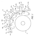
図1を参照しながら、米国特許第5,440,328号明細書に記載されたタイプのシングルパス多色感熱式プリンターに関して、本発明を説明する。このようなプリンターにおいて、受容体搬送システム、3つ又は4つ以上のサーマル・プリントヘッド集成体12, 14及び16を含むプリンター・エンジン10が設けられている。プリントヘッド集成体のそれぞれは、それぞれの再装填可能なサーマル・リボン・カセット集成体を含む。サーマル・リボン・カセット集成体には、色転写リボン12c, 14c及び16cが装填されている。サーマル・プリントヘッド集成体のそれぞれは、サーマル・プリントラインを有するサーマル・プリントヘッド19a〜dを含む。プリントヘッド集成体のそれぞれはさらに、対応部分のプラテン・ローラ13a〜cを有する。プラテン・ローラ13a〜cとそれぞれのプリントヘッドとはそれぞれのニップを形成し、そのニップを受容体11がそれぞれの色素カラーリボンと組み合わされて通過する。取付け集成体は、プリントヘッドの位置が調節されるのを可能にするので、取付け集成体はそれぞれのプラテン・ローラに向かう方向及びプラテン・ローラから離れる方向に旋回させることができる。この点に関して、取付け集成体は、プリントヘッドがプラテン・ローラから係合解離される「アップ」位置と、プリントヘッドがプラテン・ローラとのバイアス係合状態にある「ダウン」位置との間で旋回可能である。
The present invention will now be described by way of example with reference to the accompanying drawings.
With reference to FIG. 1, the present invention will be described with respect to a single-pass multicolor thermal printer of the type described in US Pat. No. 5,440,328. In such a printer, a
それぞれの再装填可能なリボン・カセット集成体は、リボン供給ロール12a, 14a又は16a、及びリボン巻取りロール12b, 14b又は16bを含むカセット本体を含む。リボン・カセット集成体には、3つ又は4つ以上の原色リボン12c, 14c及び16cのうちの1つが装填されている。これらの原色リボン12c, 14c及び16cはコンベンショナルな減法混色印刷で使用される。受容体上に画像を印刷するためにカセット集成体がプリンター内に装填されると、各リボン・カセット集成体の供給ロール及び巻取りロールが、個々のリボン駆動サブ集成体にカップリングされる。カラーリボンのそれぞれのための集成体に加えて、画像がプリントされた後に受容体にオーバーコート層を転写することができる透明リボン18cの供給部を備えたリボン・カセット集成体18を設けることもできる。透明リボン・カセット集成体は、他の集成体に全ての点で類似しており(供給ロール及び巻取りロール18a及び18bを含む)、そして画像形成されたばかりの受容体にオーバーコート層を転写するために、別個のプリントヘッドが使用される。最終プリントに艶消し又は光沢仕上げオーバーコートを提供するために、異なるタイプの透明リボンを使用することができる。或いは、透明リボンと組み合わされたプリントヘッドが、最終プリントに種々異なるオーバーコートを形成するために好適に調節されたそれぞれの記録素子を有することもできる。
Each reloadable ribbon cassette assembly includes a cassette body including a ribbon supply roll 12a, 14a or 16a and a ribbon take-
サーマル色素を受理するためのコーティングを有する受容体11は、連続的なロールとして支持されており、そしてプラテン・ローラ13a-dの周りに通される。受容体はまた、キャプスタン駆動ローラ17とバックアップ・ローラ17aとから形成されるニップに通される。受容体がキャプスタン駆動ローラによって駆動され、受容体が各サーマル・プリントヘッド集成体12, 14及び16の傍らを通ると、それぞれのカラー色素画像が受容体シートに転写されることにより、多色画像が形成される。例えば、集成体12がイエロー色分解画像を提供し、集成体14がマゼンタ色分解画像を提供し、そして集成体16がシアン色分解画像を提供することにより、受容体シート上に三色多色画像を形成することができる。第4の集成体18は、色画像を例えば指紋から保護するために、透明オーバーコートを熱転写する。4つの集成体のそれぞれにおいて、記録素子を有するサーマル・プリントヘッド19a〜dが設けられている。記録素子は、受容体にカラー色素を選択的に転写すること、又は透明リボンの場合には、画像形成されたばかりの受容体シートにオーバーコート層を転写することが、画像情報に応じて選択的に可能になる。各サーマル・プリント集成体において、プラテン・ローラ13a〜dは、それぞれのプリントヘッド19a〜dと、各プリント用ニップを形成する。受容体がそれぞれのニップを通して駆動されると、受容体の移動は、やはりそれぞれのニップを通して、対応サーマル・リボン12c, 14c, 16c及び18cを前進させる。各多色画像が形成された後、カッター15が、受容体を切断することにより、透明オーバーコート層によって保護された多色画像を含有する不連続シートにすることが可能になる。
A
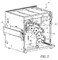
ここで図2を参照すると、図1に示されたプリンター・エンジン10を密閉するハウジングを含むプリンター装置8が示されている。図2は、サーマル・リボン・カセット集成体上に供給リボンコア及び巻取りリボンコアを装填するのを容易にするための、感熱式プリンターと組み合わされた装填補助装置を示す。種々のサーマル・プリント集成体12, 14, 16及び18が見えるようにプリンター装置の内側を示すために、前面ハウジング・ドアは取り除かれている。前面ハウジング・ドア(図示せず)が開放旋回されたときに前面の開口に示されるように、ハウジングの側壁のうちの一方に、装填補助ブラケットが支持されている。装填補助ブラケットは鉛直方向に直立するプレート20を含む。このプレート20の上縁には、2つの鉛直方向スロット21及び22が形成されている。
Referring now to FIG. 2, there is shown a
図3を参照すると、サーマル・プリント集成体のうちの1つの一部を形成する再装填可能なリボン・カセット集成体28が、スライド・レールに沿って前方に向かってスライドし、そしてプリンター・ヘッドから取り外された状態で示されている。リボン・カセット集成体が前方に向かって動かされるように、プラテン集成体9が前方に向かって動かされ、これにより、リボン・カセット集成体のいずれかのスライド移動のための空間が提供される。プラテン集成体9は、紙受容体ロール11のための支持体と、プラテン・ローラ及びキャプスタン・ローラを含む紙受容体のための駆動構成部分全てとを含む。
Referring to FIG. 3, a reloadable
図4は、リボン・カセット集成体28を、プリンター装置から取り出された状態で示す背面図、及びプリンター装置のフレームに固定された装填補助ブラケット20を示すクローズアップ図である。リボン・カセット集成体は、懸吊する右側壁29及び左側壁30、並びに前壁32及び後壁33が取り付けられた、アルミニウムから成る中央押出し部を含む。この特定のリボンのための供給ロール18a及び巻取りロール18bが、リボン・カセット集成体上に支持されている。図4に示されてはいないが、リボンは供給ロール18aから、懸吊する右側壁29及び左側壁30を巡って、巻取りロール18bまで延びることになる。リボン・カセット集成体は、適切な支持体35f, 35r, 36f及び36rを含む(図7も参照)。支持体は、それぞれの支持体上で供給ロール及び巻取りロールのそれぞれの前端部及び後端部を支持する。この点において、供給ロール及び巻取りロールのそれぞれがコアを含んでよい。このコアにリボン材料が巻かれるように適合される。それぞれのコアのための支持体は、挿入装置を含んでよい。挿入装置のそれぞれは、各コアのそれぞれの端部に係合し、コアの端部を回転のために支持する。挿入装置は後側に図示のようなピン又は突起を有することにより、コアのそれぞれの後端部に形成された係止用スロットと係合して、コアの駆動を可能にすることができる。このような挿入装置は当業者によく知られている。リボン・カセット集成体の後方の端部には、挿入装置の後端部がそれぞれ、それぞれのシャフト37及び38を介して取付けられる。シャフトは後壁33のそれぞれの開口を通って延びており、それぞれの歯車39及び40にカップリングされている。歯車はベース部材39a及び40aを含む。これらのベース部材39a及び40aは、軸方向に突出する歯列39b及び40bを有する。ベース部材39a及び40aと、後壁33との間には、装填補助ブラケット20に設けられたそれぞれのスロット21及び22内にシャフト37及び38を取り付けるのを可能にするのに十分なスペースが設けられている。
FIG. 4 is a rear view showing the
図3及び図5は、装填補助ブラケット20に取り付けられたリボン・カセット集成体28を示す。図5には、装填補助ブラケット20上に取り付けられたリボン・カセット集成体28がクローズアップ図で示されており、この図において、供給ロール及び巻取りロールは取り外され、そして新しい供給ロール及び巻取りロールを受容する用意ができている。図7において、挿入装置が、ガジオンピン35r, 35f, 36r及び36fの形態で示されている。ガジオンピンは、各コアのそれぞれの端部内部に受容されるようにばね負荷されている。図8は、付加的な構造、例えばガイドローラ45及び46をより明らかに示すリボン・カセット集成体のさらに別の図である。ガイドローラ45及び46の周りには、サーマル・リボンが巻き掛けられる。ガイドローラは、後プレート33と組み合わされた懸吊脚部48及び49、並びに前プレート32と組み合わされた懸吊脚部50及び51に設けられたそれぞれの開口内で回転するように支持される。左側壁30内部にはプレナム・チャンバー47が形成されている。プレナム・チャンバー47内に、プリンター装置内のファンから空気を吹き込むことにより、リボン・カセット集成体と組み合わされたそれぞれのプリントヘッドに空気を分配することができる。プレナム内の空気は、壁30に設けられた開口55から出ることにより、プリントヘッドと組み合わされたヒートシンク上に衝突する。
FIGS. 3 and 5 show the
図9は図1と同様の概略図であるが、しかしここでは装置の後方から見た状態を示している。図9は、プラテン・ローラ13a〜d、キャプスタン駆動ローラ17及びバックアップ・ローラ17a、及び受容体ロール11を示す。受容体がプラテン・ローラ13dと、キャプスタン駆動ローラ・バックアップ・ローラ対との間を通るのに伴って受容体の温度を測定するために、サーミスタ60が位置決めされている。サーミスタは、最後のプリント・ステーション、及び、もし設けられているならばラミネーション・プリントヘッドから下流で受容体の裏側に位置決めされている。受容体搬送経路に沿った追加のセンサーを使用することにより、受容体温度を概算することができる。例えば、プリント中に受容体を搬送するために使用されるキャプスタン・ローラ17と接触した状態で、第2のサーミスタ61が配置されている。キャプスタン・ローラ17及びサーミスタ61は、プリント・ステーションの全てを超えて配置されており、受容体がプリント中にキャプスタン・ローラによって搬送されると、熱エネルギーを蓄積する。温度測定の精度を最大にするために、多数のセンサーが見いだされている。
FIG. 9 is a schematic view similar to FIG. 1, but here shows the state as seen from the rear of the device. FIG. 9 shows the platen rollers 13a to 13d, the
図10を参照すると、サーミスタ60及び61の抵抗は、モニタリングされ、そしてそれぞれ演算増幅器(OP-AMP)62及び63によって電圧に変換される。好ましい実施態様の場合、演算増幅器の出力は、0〜5ボルトのダイナミック・レンジが好ましい。0ボルトの電圧は、プリンターが長時間にわたってアイドル・スタンバイ状態にあるときに存在するような、最小周囲受容体温度を表す。5ボルトの電圧は、連続的なプリンター作業を通して達成された最大受容体温度を表す。
Referring to FIG. 10, the resistances of the
演算増幅器の動的電圧出力は好ましくは、それぞれ、アナログ-デジタル変換器(A/D)64及び65によって、そしてルックアップ・テーブル(LUT)66及び67によって、代表デジタル値に変換される。このプロセスは、測定された温度値がデジタル値に表されるのを可能にする。0ボルトは、デジタル値ゼロを生成し、そして5ボルトは、デジタル値24を生成する。0と5との間の電圧は、温度差に関して、受容体が直面する搬送特性変化の非線形数学モデルから導出されたデジタル値と一致する。デジタル値は、デジタル-アナログ変換器(DAC)68によってアナログに変換され、そしてステップモーター70の制御回路内に一体化される。ステップモーター70は、図11に示された受容体駆動集成体の一部である。
The dynamic voltage output of the operational amplifier is preferably converted to representative digital values by analog-to-digital converters (A / D) 64 and 65, and by look-up tables (LUT) 66 and 67, respectively. This process allows the measured temperature value to be represented in a digital value. 0 volts produces a digital value of zero and 5 volts produces a digital value of 24. The voltage between 0 and 5 is consistent with a digital value derived from a nonlinear mathematical model of the transport property change encountered by the receptor with respect to the temperature difference. The digital value is converted to analog by a digital-to-analog converter (DAC) 68 and integrated into the control circuit of the
ステップモーター70を使用することにより、モーター・プーリー72、ベルト74、中間プーリー76、第2のベルト78、駆動プーリー80及びキャプスタン駆動カップリング82を介して、受容体を搬送する。デジタル値が増大するにつれて、モーターのステップ速度は、存在するデジタル値に応じて小さな増分で増大される。このことは、画像受容体の搬送速度を増大させる。
By using the
ここに説明した画像見当合わせ改善手段は、プリンターの平均ラスター・ライン・ピッチのシムを生じさせる目的で、ステップモーター68の速度を微調整するのを可能にする。
The image registration improvement means described herein allows the speed of the
ステップモーターはしばしば、2つの巻き線におけるサイン/コサイン電流波形をシミュレートする、順序付けられた励起で駆動される。この曲線形状は、1電気サイクル当たりNマイクロステップのシーケンス、又は換言すれば、1モーター全ステップ当たりN/4マイクロステップのシーケンスから成る量子化形態で実現される。Nマイクロステップによって支配される変位は、プリンターのラスター・ライン・ピッチを決定する。最も簡単な実施例の場合、Nマイクロステップの各シーケンスは常に、2つの巻き線の一方に対して同じN個のサイン誘導電流値を繰り返し、そして、2つの巻き線の他方に対して同じN個のコサイン誘導電流値を繰り返す。これは好ましくは、デジタル-アナログ変換器68にデジタル入力を供給するルックアップ・テーブル66によって実行される。ルックアップ・テーブル66は、2つの巻き線のそれぞれに対してN個のルックアップ値を有する。
Step motors are often driven with ordered excitations that simulate sine / cosine current waveforms in the two windings. This curve shape is realized in a quantized form consisting of a sequence of N microsteps per electrical cycle, or in other words, a sequence of N / 4 microsteps per motor step. The displacement governed by N microsteps determines the printer's raster line pitch. In the simplest embodiment, each sequence of N microsteps always repeats the same N sine induction current values for one of the two windings, and the same N for the other of the two windings. Repeat cosine induced current values. This is preferably performed by a look-up table 66 that provides a digital input to a digital to
存在するN個のルックアップ値の整数倍数(値K)で、ルックアップ・テーブル66をより微細にコードし、サイン/コサイン波形をより微細な標準に記述することにより、所定の程度の速度調節を実現することができる。上述の状況に等しい性能は、各マイクロステップにおけるテーブル前進が、上述の技術における「ONE」の潜在的な値の代わりに、今や整数Kによって支配される場合に達成されることになる。ステップは、1ラスター・ライン当たりNマイクロステップで進行することになる。整数値によって値Kから1マイクロステップ当たりのテーブル前進を変える(値J)ことにより、Nマイクロステップ全体にわたるモーターの変位は、スピードアップ(J>Kの場合)又はスローダウン(J<Kの場合)することになる。マイクロステップ間の時間インターバルは変化させられないものと推定される。むしろそれぞれのステップと関連する変位が変化させられ、従ってラスター・ライン・ピッチはこれに応じて、全モーター電気サイクルと関連するピッチよりも長く又は短くなる。達成され得る速度等級付けは、コントローラ・メモリー内で構成されるべき実現可能な基準テーブル・サイズによって、そしてまたモーター制御ハードウェア内のデジタル-アナログ変換器68の分解能によって制限される。
A certain degree of speed adjustment by coding the lookup table 66 more finely and describing the sine / cosine waveform in a finer standard with an integer multiple (value K) of the N lookup values present Can be realized. A performance equal to the situation described above will be achieved if the table advance in each microstep is now dominated by the integer K instead of the potential value of “ONE” in the technique described above. The step will proceed with N microsteps per raster line. By changing the table advance per microstep from the value K by an integer value (value J), the displacement of the motor across N microsteps is either speeded up (if J> K) or slowed down (if J <K ). It is estimated that the time interval between microsteps cannot be changed. Rather, the displacement associated with each step is changed so that the raster line pitch is accordingly longer or shorter than the pitch associated with the full motor electrical cycle. The speed grading that can be achieved is limited by the feasible reference table size to be configured in the controller memory and also by the resolution of the digital-to-
マイクロステップのシーケンス全体にわたって、前進指数Jの一連の非定常値を採用することにより、平均ラスター・ライン・ピッチの別の程度の調節を達成することができる。1ラスター・ライン上の総変位は、N x K個の要素の公称テーブル変位であってよく、そして、整数値によって調節可能であることにより、N x Kの1部分の分解能に合わせた調節を達成することができる。 By adopting a series of unsteady values of the forward index J throughout the microstep sequence, another degree of adjustment of the average raster line pitch can be achieved. The total displacement on one raster line can be a nominal table displacement of N x K elements, and can be adjusted by an integer value to adjust to the resolution of one part of N x K. Can be achieved.
このことを実施するための必要な構成要件は、マイクロステップ前進テーブルを構成することである。マイクロステップ前進テーブルは、マイクロステップ毎に指数前進値「J」に割り当てられるべき一連の値を保持することになる。マイクロステップ前進テーブルは、N個の長さの要素となり、ラスター・ライン毎に反復する。 A necessary component to do this is to configure a microstep advance table. The microstep advance table will hold a series of values to be assigned to the exponent advance value “J” for each microstep. The microstep advance table becomes an element of N lengths and repeats every raster line.
マイクロステップ前進テーブルのM x N個の長さの要素を形成することにより、そして、一連のM個のラスター・ラインが不均一マイクロステップ前進シーケンスのサイクル時間であると断じることにより、さらに微細な制御を考えることができる。これにより、M x N x Kの1部分の分解能に合わせて、平均ラスター・ライン前進を調節することができるようになる。例えば、この技術はN = 24、K = 30、及びM = 12の値で実施することができる。 By forming the M x N length elements of the microstep advance table, and declining that the series of M raster lines is the cycle time of the non-uniform microstep advance sequence, Fine control can be considered. This allows the average raster line advancement to be adjusted to the resolution of one part of M x N x K. For example, this technique can be implemented with values of N = 24, K = 30, and M = 12.
Claims (21)
該経路に沿って該受容体を前進させるように適合された、速度調節可能な受容体駆動機構、
該経路に沿って該受容体の温度を検出するように適合されたセンサー、及び、
該受容体の温度の変化を補償するために該プリンターの平均ラスター・ライン・ピッチのシムを生じさせるように、該駆動機構の速度を該受容体の検出された温度の関数として調節するように適合されたコントローラ
を含んで成る感熱式プリンター装置。 A thermal printer apparatus having a plurality of print stations for recording image information on a receiver web moving along a path through a plurality of print stations having a predetermined average raster line pitch. ,
A rate adjustable receptor drive mechanism adapted to advance the receptor along the path;
A sensor adapted to detect the temperature of the receptor along the path; and
Adjusting the speed of the drive as a function of the detected temperature of the receiver to produce a shim of the average raster line pitch of the printer to compensate for changes in the temperature of the receptor A thermal printer device comprising an adapted controller.
該センサーが、前記複数のプリント・ステーションの全てを超え且つ該ローラの手前の該経路に沿った位置で該受容体の温度を感知するように適合されている、
請求項1に記載の感熱式プリンター装置。 The drive mechanism includes a roller, and the sensor is adapted to sense the temperature of the receiver at a location along all of the plurality of print stations and along the path in front of the roller. ,
2. The thermal printer apparatus according to claim 1.
ステップモーターを含み、
該プリンターの平均ラスター・ライン・ピッチのシムを生じさせる目的で該ステップモーターの速度調節を提供するために、該ステップモーターのステップ速度を、該受容体の検出された温度の関数として増大させる、
請求項1に記載の感熱式プリンター装置。 The drive mechanism is
Including stepper motor,
Increasing the stepping motor's step speed as a function of the detected temperature of the receptor to provide a speed adjustment of the stepping motor for the purpose of producing an average raster line pitch shim of the printer;
2. The thermal printer apparatus according to claim 1.
色素を有するサーマル・リボンを貯蔵するためのリボン・カセット集成体、該リボン・カセット集成体は、供給リボンコアと、巻取りリボンコアと、該供給リボンコアを支持するように適合された供給リボン支持体と、該巻取りリボンコアを支持するように適合された巻取りリボン支持体とを含む;
該サーマル・リボンから移動中の受容体に色素を転写するために該サーマル・リボンと係合した状態で位置決め可能な伸長したサーマル・プリントヘッド、該プリントヘッドは、移動している受容体の前進方向に対して垂直な主走査記録方向に配列された複数の記録素子を有し、主走査記録方向は、該プリントヘッドの伸長方向でもある;
前記前進方向で該経路に沿って受容体を前進させるように適合された速度調節可能な受容体駆動機構;
該経路に沿って該受容体の温度を検出するように適合されたセンサー;及び
該受容体の温度の変化を補償するために該プリンターの平均ラスター・ライン・ピッチのシムを生じさせるように、該駆動機構の速度を該受容体の検出された温度の関数として調節するように適合されたコントローラ
を含んで成る。 A thermal printer device for recording image information on a receiver moving through a plurality of print stations having a predetermined average raster line pitch, the device comprising:
Ribbon cassette assembly for storing a thermal ribbon having a dye, the ribbon cassette assembly comprising: a supply ribbon core; a take-up ribbon core; and a supply ribbon support adapted to support the supply ribbon core A take-up ribbon support adapted to support the take-up ribbon core;
An elongated thermal printhead positionable in engagement with the thermal ribbon to transfer dye from the thermal ribbon to the moving receiver, the printhead being advanced by the moving receiver A plurality of recording elements arranged in a main scanning recording direction perpendicular to the direction, and the main scanning recording direction is also an extension direction of the print head;
A rate-adjustable receptor drive mechanism adapted to advance the receptor along the path in the advance direction;
A sensor adapted to detect the temperature of the receptor along the path; and to produce a shim of the average raster line pitch of the printer to compensate for changes in the temperature of the receptor; A controller adapted to adjust the speed of the drive mechanism as a function of the detected temperature of the receptor.
前記1つのリボン・カセット集成体と前記各プリントヘッドが組み合わされた、複数の前記リボン・カセット集成体と複数の前記プリントヘッドとがある、
請求項6に記載の感熱式プリンター装置。 The printer device is a multi-color printer device, and there are a plurality of ribbon cassette assemblies and a plurality of print heads, wherein the one ribbon cassette assembly and each print head are combined;
The thermal printer apparatus according to claim 6.
複数のプリント・ステーションを通って経路に沿って受容体を移動し、
該経路に沿って該受容体の温度を検出し、そして
該受容体の温度の変化を補償するために該プリンターの平均ラスター・ライン・ピッチのシムを生じさせるように、該受容体の速度を該受容体の検出された温度の関数として調節する、
各工程を含んで成る。 A method of recording image information on a receiver moving along a path through a plurality of print stations having a predetermined average raster line pitch, the method comprising:
Move the receptor along the path through multiple print stations,
Detect the temperature of the receptor along the path, and adjust the speed of the receptor to produce an average raster line pitch shim for the printer to compensate for changes in the temperature of the receptor. Adjusting as a function of the detected temperature of the receptor;
Each step is included.
該調節工程が、該プリンターの平均ラスター・ライン・ピッチのシムを生じさせる目的で該ステップモーターの速度調節を提供するために、該ステップモーターのステップ速度を、該受容体の検出された温度の関数として増大させることを含む、
請求項9に記載の方法。 The moving step includes using a step motor, and the adjusting step includes providing a step motor speed adjustment for the purpose of producing a shim for the average raster line pitch of the printer. Increasing the motor step speed as a function of the detected temperature of the receptor,
The method of claim 9.
複数のプリント・ステーションを通って経路に沿って受容体を移動し、
該経路に沿った受容体の温度の関数である値を有する電気信号を生成し、そして、
該受容体の温度の変化を補償するために該プリンターの平均ラスター・ライン・ピッチのシムを生じさせるように、該電気信号を使用して該受容体の速度を調節する、
工程を含んで成る。 A method of recording image information on a receiver moving along a path through a plurality of print stations having a predetermined average raster line pitch, the method comprising:
Move the receptor along the path through multiple print stations,
Generating an electrical signal having a value that is a function of the temperature of the receptor along the path; and
Adjusting the speed of the receptor using the electrical signal to produce a shim of the average raster line pitch of the printer to compensate for changes in the temperature of the receptor;
Comprising the steps.
該経路に沿って該受容体を前進させるように適合された速度調節可能な受容体駆動機構、
該経路に沿って該受容体及び表面の温度を検出するように適合された複数のセンサー、及び、
該プリンターの平均ラスター・ライン・ピッチのシムを生じさせるよう該駆動機構の速度を該受容体の検出された温度の関数として調節することにより、該受容体の温度の変化を補償するように適合されているコントローラ、
を含んで成る。 A thermal printer apparatus having a plurality of print stations for recording image information on a receiver web moving along a path through a plurality of print stations having a predetermined average raster line pitch. The device is
A rate adjustable receptor drive mechanism adapted to advance the receptor along the path;
A plurality of sensors adapted to detect the temperature of the receptor and the surface along the path; and
Adapted to compensate for changes in the temperature of the receptor by adjusting the speed of the drive mechanism as a function of the detected temperature of the receptor to produce a shim for the average raster line pitch of the printer Controller,
Comprising.
該センサーのうちの1つが、前記複数のプリント・ステーションの全てを超え且つ該キャプスタン駆動ローラの手前の該経路に沿った位置で該受容体の温度を感知するように適合されており、そして
該センサーのうちの別のセンサーが、該キャプスタン駆動ローラの表面の温度を感知するように適合されている、
請求項1に記載の感熱式プリンター装置。 The drive mechanism includes a capstan drive roller;
One of the sensors is adapted to sense the temperature of the receiver across all of the plurality of print stations and along the path in front of the capstan drive roller; and Another of the sensors is adapted to sense the temperature of the surface of the capstan drive roller;
2. The thermal printer apparatus according to claim 1.
ステップモーターを含み、
該プリンターの平均ラスター・ライン・ピッチのシムを生じさせる目的で該ステップモーターの速度調節を提供するために、該ステップモーターのステップ速度を、該受容体の検出された温度の関数として増大させる、
請求項15に記載の感熱式プリンター装置。 The drive mechanism is
Including stepper motor,
Increasing the stepping motor's step speed as a function of the detected temperature of the receptor to provide a speed adjustment of the stepping motor for the purpose of producing an average raster line pitch shim of the printer;
The thermal printer apparatus according to claim 15.
色素を有するサーマル・リボンを貯蔵するためのリボン・カセット集成体、該リボン・カセット集成体は、供給リボンコアと、巻取りリボンコアと、該供給リボンコアを支持するように適合された供給リボン支持体と、該巻取りリボンコアを支持するように適合された巻取りリボン支持体とを含む;
該サーマル・リボンから移動中の受容体に色素を転写するために該サーマル・リボンと係合した状態で位置決め可能な伸長したサーマル・プリントヘッド、該プリントヘッドは、移動している受容体の前進方向に対して垂直な主走査記録方向に配列された複数の記録素子を有し、主走査記録方向は、該プリントヘッドの伸長方向でもある;
前記前進方向で該経路に沿って受容体を前進させるように適合された速度調節可能な受容体駆動機構;
該経路に沿って該受容体及び表面の温度を検出するように適合された複数のセンサー;及び
該受容体の温度の変化を補償するために該プリンターの平均ラスター・ライン・ピッチのシムを生じさせるように、該駆動機構の速度を検出された温度の関数として調節するように適合されたコントローラ
を含んで成る。 A thermal printer device for recording image information on a receiver moving through a plurality of print stations having a predetermined average raster line pitch, the device comprising:
Ribbon cassette assembly for storing a thermal ribbon having a dye, the ribbon cassette assembly comprising: a supply ribbon core; a take-up ribbon core; and a supply ribbon support adapted to support the supply ribbon core A take-up ribbon support adapted to support the take-up ribbon core;
An elongated thermal printhead positionable in engagement with the thermal ribbon to transfer dye from the thermal ribbon to the moving receiver, the printhead being advanced by the moving receiver A plurality of recording elements arranged in a main scanning recording direction perpendicular to the direction, and the main scanning recording direction is also an extension direction of the print head;
A rate-adjustable receptor drive mechanism adapted to advance the receptor along the path in the advance direction;
A plurality of sensors adapted to detect the temperature of the receptor and the surface along the path; and a shim of the average raster line pitch of the printer to compensate for changes in the temperature of the receptor A controller adapted to adjust the speed of the drive mechanism as a function of the detected temperature.
Applications Claiming Priority (2)
| Application Number | Priority Date | Filing Date | Title |
|---|---|---|---|
| US10/780,304 US6999108B2 (en) | 2004-02-17 | 2004-02-17 | Method and apparatus for image registration improvements in a printer having plural printing stations |
| PCT/US2005/002195 WO2005082627A2 (en) | 2004-02-17 | 2005-01-25 | Method and apparatus for image printer registration |
Publications (2)
| Publication Number | Publication Date |
|---|---|
| JP2007522969A true JP2007522969A (en) | 2007-08-16 |
| JP2007522969A5 JP2007522969A5 (en) | 2008-03-06 |
Family
ID=34838563
Family Applications (1)
| Application Number | Title | Priority Date | Filing Date |
|---|---|---|---|
| JP2006554103A Pending JP2007522969A (en) | 2004-02-17 | 2005-01-25 | Image printer and method and apparatus for registration |
Country Status (4)
| Country | Link |
|---|---|
| US (1) | US6999108B2 (en) |
| EP (1) | EP1716002A2 (en) |
| JP (1) | JP2007522969A (en) |
| WO (1) | WO2005082627A2 (en) |
Cited By (3)
| Publication number | Priority date | Publication date | Assignee | Title |
|---|---|---|---|---|
| JP2010120287A (en) * | 2008-11-20 | 2010-06-03 | Mitsubishi Electric Corp | Thermal transfer recording device |
| KR101061643B1 (en) | 2009-02-18 | 2011-09-01 | 미쓰비시덴키 가부시키가이샤 | How to remove the thermal transfer printer and ink cassette |
| JP2014506839A (en) * | 2010-11-15 | 2014-03-20 | ジーアイエイチ・コーポレーション | Media processing device and related system |
Families Citing this family (2)
| Publication number | Priority date | Publication date | Assignee | Title |
|---|---|---|---|---|
| US9020595B2 (en) * | 2003-12-24 | 2015-04-28 | Cardiac Pacemakers, Inc. | Baroreflex activation therapy with conditional shut off |
| US8169453B2 (en) * | 2008-07-31 | 2012-05-01 | Eastman Kodak Company | Thermally conductive, electrically isolated peel member assembly |
Family Cites Families (10)
| Publication number | Priority date | Publication date | Assignee | Title |
|---|---|---|---|---|
| JPS5911268A (en) | 1982-07-12 | 1984-01-20 | Hitachi Ltd | Printer |
| JPS60258575A (en) | 1984-06-05 | 1985-12-20 | Ricoh Co Ltd | Copying device |
| JPH04236565A (en) | 1991-01-18 | 1992-08-25 | Pfu Ltd | Paper carrier control system for original reader |
| JP2642805B2 (en) | 1991-08-02 | 1997-08-20 | 三菱電機株式会社 | Printer device |
| US5196864A (en) * | 1991-08-12 | 1993-03-23 | Eastman Kodak Company | Electronic registration in a multiple printhead thermal printer |
| JP2716910B2 (en) * | 1991-09-05 | 1998-02-18 | 三菱電機株式会社 | Thermal printer |
| US5440328A (en) * | 1992-10-05 | 1995-08-08 | Atlantek, Inc. | Single-pass multi-color thermal printer |
| JP3408071B2 (en) * | 1996-07-31 | 2003-05-19 | キヤノン株式会社 | Image forming device |
| JPH11157113A (en) | 1997-11-28 | 1999-06-15 | Victor Co Of Japan Ltd | Thermal transfer printer and thermal head used in the same |
| EP1156384B1 (en) * | 2000-05-17 | 2008-04-16 | Eastman Kodak Company | Method and apparatus for adjusting registration in a colour printer and colour printer |
-
2004
- 2004-02-17 US US10/780,304 patent/US6999108B2/en not_active Expired - Lifetime
-
2005
- 2005-01-25 WO PCT/US2005/002195 patent/WO2005082627A2/en not_active Application Discontinuation
- 2005-01-25 JP JP2006554103A patent/JP2007522969A/en active Pending
- 2005-01-25 EP EP05711916A patent/EP1716002A2/en not_active Withdrawn
Cited By (3)
| Publication number | Priority date | Publication date | Assignee | Title |
|---|---|---|---|---|
| JP2010120287A (en) * | 2008-11-20 | 2010-06-03 | Mitsubishi Electric Corp | Thermal transfer recording device |
| KR101061643B1 (en) | 2009-02-18 | 2011-09-01 | 미쓰비시덴키 가부시키가이샤 | How to remove the thermal transfer printer and ink cassette |
| JP2014506839A (en) * | 2010-11-15 | 2014-03-20 | ジーアイエイチ・コーポレーション | Media processing device and related system |
Also Published As
| Publication number | Publication date |
|---|---|
| EP1716002A2 (en) | 2006-11-02 |
| US6999108B2 (en) | 2006-02-14 |
| WO2005082627A2 (en) | 2005-09-09 |
| US20050179764A1 (en) | 2005-08-18 |
| WO2005082627A3 (en) | 2005-10-20 |
Similar Documents
| Publication | Publication Date | Title |
|---|---|---|
| US9004629B2 (en) | Image quality by printing frequency adjustment using belt surface velocity measurement | |
| US8434847B2 (en) | System and method for dynamic stretch reflex printing | |
| US8042933B2 (en) | Forceless support frame for printhead shuttle in digital printers | |
| US8714729B2 (en) | Modular roll bar assembly with temperature control system for heating or cooling web | |
| US5847742A (en) | Color thermal printer and color thermal printer method | |
| JP6548416B2 (en) | Recording device, control method of recording device, and program | |
| US20050271866A1 (en) | Method of differentiating types of heat sensitive paper | |
| US6549224B2 (en) | Adjustable printhead loading device and method for document imaging apparatus | |
| JP2012101534A (en) | Method and system for reflex printing to compensate for registration errors in continuous web inkjet printer | |
| JP2007522969A (en) | Image printer and method and apparatus for registration | |
| US20060098038A1 (en) | Method and apparatus for compensating for energy difference of thermal print head | |
| JP2012061855A (en) | Reflex printing | |
| US6499827B2 (en) | Apparatus and method of compensating for print engine and encoder expansion or contraction in a printing device | |
| KR20060098760A (en) | Continuous printer and sectional register controlling method thereof | |
| JP2007301943A (en) | Printing apparatus | |
| JP2877542B2 (en) | Image recording device | |
| JPS6239261A (en) | Recorder | |
| WO2020054007A1 (en) | Thermal transfer printer | |
| WO2022163096A1 (en) | Image forming device and image forming method | |
| JP2019166691A (en) | Image formation apparatus | |
| JPH06122262A (en) | Ink sheet driving system | |
| JP4565555B2 (en) | Recording paper transport device and recording paper transport adjustment method | |
| JP2006326908A (en) | Printer | |
| JPH05124236A (en) | Multi-color heat-sensitive recording apparatus | |
| JPH1016270A (en) | Thermal head, manufacture thereof and thermal printer employing it |
Legal Events
| Date | Code | Title | Description |
|---|---|---|---|
| A521 | Written amendment |
Free format text: JAPANESE INTERMEDIATE CODE: A523 Effective date: 20080111 |
|
| A621 | Written request for application examination |
Free format text: JAPANESE INTERMEDIATE CODE: A621 Effective date: 20080111 |
|
| A977 | Report on retrieval |
Free format text: JAPANESE INTERMEDIATE CODE: A971007 Effective date: 20090218 |
|
| A131 | Notification of reasons for refusal |
Free format text: JAPANESE INTERMEDIATE CODE: A131 Effective date: 20090224 |
|
| A02 | Decision of refusal |
Free format text: JAPANESE INTERMEDIATE CODE: A02 Effective date: 20090721 |