JP2007516830A - Self-separating pleated filter insert - Google Patents
Self-separating pleated filter insert Download PDFInfo
- Publication number
- JP2007516830A JP2007516830A JP2006547167A JP2006547167A JP2007516830A JP 2007516830 A JP2007516830 A JP 2007516830A JP 2006547167 A JP2006547167 A JP 2006547167A JP 2006547167 A JP2006547167 A JP 2006547167A JP 2007516830 A JP2007516830 A JP 2007516830A
- Authority
- JP
- Japan
- Prior art keywords
- pleated filter
- filter insert
- filter
- length
- frame
- Prior art date
- Legal status (The legal status is an assumption and is not a legal conclusion. Google has not performed a legal analysis and makes no representation as to the accuracy of the status listed.)
- Withdrawn
Links
- 238000001914 filtration Methods 0.000 claims abstract description 28
- 239000000463 material Substances 0.000 claims description 13
- -1 polypropylene Polymers 0.000 claims description 8
- 239000004743 Polypropylene Substances 0.000 claims description 7
- 229920001155 polypropylene Polymers 0.000 claims description 7
- 239000000835 fiber Substances 0.000 claims description 4
- 230000035699 permeability Effects 0.000 claims description 4
- 238000009434 installation Methods 0.000 description 8
- 238000009998 heat setting Methods 0.000 description 6
- 230000006870 function Effects 0.000 description 4
- 238000010438 heat treatment Methods 0.000 description 3
- 239000002184 metal Substances 0.000 description 3
- 238000000034 method Methods 0.000 description 3
- 238000011084 recovery Methods 0.000 description 3
- XECAHXYUAAWDEL-UHFFFAOYSA-N acrylonitrile butadiene styrene Chemical compound C=CC=C.C=CC#N.C=CC1=CC=CC=C1 XECAHXYUAAWDEL-UHFFFAOYSA-N 0.000 description 2
- 239000004676 acrylonitrile butadiene styrene Substances 0.000 description 2
- 229920000122 acrylonitrile butadiene styrene Polymers 0.000 description 2
- 239000000853 adhesive Substances 0.000 description 2
- 230000001070 adhesive effect Effects 0.000 description 2
- 238000010276 construction Methods 0.000 description 2
- 229920005669 high impact polystyrene Polymers 0.000 description 2
- 239000004797 high-impact polystyrene Substances 0.000 description 2
- 238000004519 manufacturing process Methods 0.000 description 2
- 230000007246 mechanism Effects 0.000 description 2
- 239000004033 plastic Substances 0.000 description 2
- 229920003023 plastic Polymers 0.000 description 2
- 125000006850 spacer group Chemical group 0.000 description 2
- 229920001169 thermoplastic Polymers 0.000 description 2
- 239000004698 Polyethylene Substances 0.000 description 1
- 238000004378 air conditioning Methods 0.000 description 1
- 230000000712 assembly Effects 0.000 description 1
- 238000000429 assembly Methods 0.000 description 1
- 230000015572 biosynthetic process Effects 0.000 description 1
- 239000011111 cardboard Substances 0.000 description 1
- 239000011093 chipboard Substances 0.000 description 1
- 239000000356 contaminant Substances 0.000 description 1
- 238000001816 cooling Methods 0.000 description 1
- 230000003111 delayed effect Effects 0.000 description 1
- 230000005611 electricity Effects 0.000 description 1
- 239000011888 foil Substances 0.000 description 1
- 238000007373 indentation Methods 0.000 description 1
- 238000001746 injection moulding Methods 0.000 description 1
- 230000004048 modification Effects 0.000 description 1
- 238000012986 modification Methods 0.000 description 1
- 238000000465 moulding Methods 0.000 description 1
- 239000011087 paperboard Substances 0.000 description 1
- 230000000704 physical effect Effects 0.000 description 1
- 239000002985 plastic film Substances 0.000 description 1
- 229920006255 plastic film Polymers 0.000 description 1
- 229920000573 polyethylene Polymers 0.000 description 1
- 239000004800 polyvinyl chloride Substances 0.000 description 1
- 229920000915 polyvinyl chloride Polymers 0.000 description 1
- 230000008569 process Effects 0.000 description 1
- 230000002787 reinforcement Effects 0.000 description 1
- 239000005060 rubber Substances 0.000 description 1
- 230000003068 static effect Effects 0.000 description 1
- 229920001187 thermosetting polymer Polymers 0.000 description 1
- 239000004416 thermosoftening plastic Substances 0.000 description 1
- 238000011144 upstream manufacturing Methods 0.000 description 1
- 230000000007 visual effect Effects 0.000 description 1
- 239000002699 waste material Substances 0.000 description 1
Images


Classifications
-
- B—PERFORMING OPERATIONS; TRANSPORTING
- B01—PHYSICAL OR CHEMICAL PROCESSES OR APPARATUS IN GENERAL
- B01D—SEPARATION
- B01D46/00—Filters or filtering processes specially modified for separating dispersed particles from gases or vapours
- B01D46/52—Particle separators, e.g. dust precipitators, using filters embodying folded corrugated or wound sheet material
- B01D46/521—Particle separators, e.g. dust precipitators, using filters embodying folded corrugated or wound sheet material using folded, pleated material
- B01D46/523—Particle separators, e.g. dust precipitators, using filters embodying folded corrugated or wound sheet material using folded, pleated material with means for maintaining spacing between the pleats or folds
-
- B—PERFORMING OPERATIONS; TRANSPORTING
- B01—PHYSICAL OR CHEMICAL PROCESSES OR APPARATUS IN GENERAL
- B01D—SEPARATION
- B01D29/00—Filters with filtering elements stationary during filtration, e.g. pressure or suction filters, not covered by groups B01D24/00 - B01D27/00; Filtering elements therefor
- B01D29/01—Filters with filtering elements stationary during filtration, e.g. pressure or suction filters, not covered by groups B01D24/00 - B01D27/00; Filtering elements therefor with flat filtering elements
- B01D29/05—Filters with filtering elements stationary during filtration, e.g. pressure or suction filters, not covered by groups B01D24/00 - B01D27/00; Filtering elements therefor with flat filtering elements supported
- B01D29/07—Filters with filtering elements stationary during filtration, e.g. pressure or suction filters, not covered by groups B01D24/00 - B01D27/00; Filtering elements therefor with flat filtering elements supported with corrugated, folded or wound filtering sheets
-
- B—PERFORMING OPERATIONS; TRANSPORTING
- B01—PHYSICAL OR CHEMICAL PROCESSES OR APPARATUS IN GENERAL
- B01D—SEPARATION
- B01D29/00—Filters with filtering elements stationary during filtration, e.g. pressure or suction filters, not covered by groups B01D24/00 - B01D27/00; Filtering elements therefor
- B01D29/96—Filters with filtering elements stationary during filtration, e.g. pressure or suction filters, not covered by groups B01D24/00 - B01D27/00; Filtering elements therefor in which the filtering elements are moved between filtering operations; Particular measures for removing or replacing the filtering elements; Transport systems for filters
-
- B—PERFORMING OPERATIONS; TRANSPORTING
- B01—PHYSICAL OR CHEMICAL PROCESSES OR APPARATUS IN GENERAL
- B01D—SEPARATION
- B01D39/00—Filtering material for liquid or gaseous fluids
- B01D39/14—Other self-supporting filtering material ; Other filtering material
- B01D39/16—Other self-supporting filtering material ; Other filtering material of organic material, e.g. synthetic fibres
- B01D39/1607—Other self-supporting filtering material ; Other filtering material of organic material, e.g. synthetic fibres the material being fibrous
- B01D39/1623—Other self-supporting filtering material ; Other filtering material of organic material, e.g. synthetic fibres the material being fibrous of synthetic origin
-
- B—PERFORMING OPERATIONS; TRANSPORTING
- B01—PHYSICAL OR CHEMICAL PROCESSES OR APPARATUS IN GENERAL
- B01D—SEPARATION
- B01D46/00—Filters or filtering processes specially modified for separating dispersed particles from gases or vapours
- B01D46/10—Particle separators, e.g. dust precipitators, using filter plates, sheets or pads having plane surfaces
-
- B—PERFORMING OPERATIONS; TRANSPORTING
- B01—PHYSICAL OR CHEMICAL PROCESSES OR APPARATUS IN GENERAL
- B01D—SEPARATION
- B01D2265/00—Casings, housings or mounting for filters specially adapted for separating dispersed particles from gases or vapours
- B01D2265/02—Non-permanent measures for connecting different parts of the filter
- B01D2265/028—Snap, latch or clip connecting means
-
- B—PERFORMING OPERATIONS; TRANSPORTING
- B01—PHYSICAL OR CHEMICAL PROCESSES OR APPARATUS IN GENERAL
- B01D—SEPARATION
- B01D2275/00—Filter media structures for filters specially adapted for separating dispersed particles from gases or vapours
- B01D2275/20—Shape of filtering material
- B01D2275/203—Shapes flexible in their geometry, e.g. bendable, adjustable to a certain size
-
- Y—GENERAL TAGGING OF NEW TECHNOLOGICAL DEVELOPMENTS; GENERAL TAGGING OF CROSS-SECTIONAL TECHNOLOGIES SPANNING OVER SEVERAL SECTIONS OF THE IPC; TECHNICAL SUBJECTS COVERED BY FORMER USPC CROSS-REFERENCE ART COLLECTIONS [XRACs] AND DIGESTS
- Y10—TECHNICAL SUBJECTS COVERED BY FORMER USPC
- Y10S—TECHNICAL SUBJECTS COVERED BY FORMER USPC CROSS-REFERENCE ART COLLECTIONS [XRACs] AND DIGESTS
- Y10S55/00—Gas separation
- Y10S55/31—Filter frame
-
- Y—GENERAL TAGGING OF NEW TECHNOLOGICAL DEVELOPMENTS; GENERAL TAGGING OF CROSS-SECTIONAL TECHNOLOGIES SPANNING OVER SEVERAL SECTIONS OF THE IPC; TECHNICAL SUBJECTS COVERED BY FORMER USPC CROSS-REFERENCE ART COLLECTIONS [XRACs] AND DIGESTS
- Y10—TECHNICAL SUBJECTS COVERED BY FORMER USPC
- Y10T—TECHNICAL SUBJECTS COVERED BY FORMER US CLASSIFICATION
- Y10T428/00—Stock material or miscellaneous articles
- Y10T428/24—Structurally defined web or sheet [e.g., overall dimension, etc.]
- Y10T428/24628—Nonplanar uniform thickness material
- Y10T428/24669—Aligned or parallel nonplanarities
- Y10T428/24686—Pleats or otherwise parallel adjacent folds
-
- Y—GENERAL TAGGING OF NEW TECHNOLOGICAL DEVELOPMENTS; GENERAL TAGGING OF CROSS-SECTIONAL TECHNOLOGIES SPANNING OVER SEVERAL SECTIONS OF THE IPC; TECHNICAL SUBJECTS COVERED BY FORMER USPC CROSS-REFERENCE ART COLLECTIONS [XRACs] AND DIGESTS
- Y10—TECHNICAL SUBJECTS COVERED BY FORMER USPC
- Y10T—TECHNICAL SUBJECTS COVERED BY FORMER US CLASSIFICATION
- Y10T428/00—Stock material or miscellaneous articles
- Y10T428/24—Structurally defined web or sheet [e.g., overall dimension, etc.]
- Y10T428/24628—Nonplanar uniform thickness material
- Y10T428/24669—Aligned or parallel nonplanarities
- Y10T428/24694—Parallel corrugations
Landscapes
- Chemical & Material Sciences (AREA)
- Chemical Kinetics & Catalysis (AREA)
- Filtering Of Dispersed Particles In Gases (AREA)
- Filtering Materials (AREA)
Abstract
二次間隔構造を使用しなくても再利用可能なフィルタフレーム内に容易に設置することができる交換可能な自己隔置性ひだ付きフィルタ挿入体(8)は、フィルタが伸長されると均一に伸長する複数のひだを含む可逆的に折りたたみ可能および伸長可能なろ過媒体(10)を含む。フィルタがフィルタフレームの長さまで伸長されると、フィルタに張力がかかってばねのように挙動し、それにより、フレーム(2)の長さに合わせるためにフィルタの長さを容易に調整することができ、フレーム内に提供された対応するリブ(32)とひだの位置を合わせることができる。
The replaceable self-spaced pleated filter insert (8) that can be easily installed in a reusable filter frame without the use of a secondary spacing structure ensures that the filter is evenly stretched A reversibly foldable and extensible filtration medium (10) comprising a plurality of elongating pleats. When the filter is extended to the length of the filter frame, the filter is tensioned and behaves like a spring so that the length of the filter can be easily adjusted to match the length of the frame (2). And the pleats can be aligned with the corresponding ribs (32) provided in the frame.
Description
本発明は、一般に、フィルタに関し、特に、再利用可能なフレームに挿入される着脱自在のフィルタ挿入体に関する。 The present invention relates generally to filters, and more particularly to a detachable filter insert that is inserted into a reusable frame.
多くの従来の住宅用加熱冷却システムは使い捨てのフィルタを含んでいる。このようなフィルタは、フレームと、繊維状フィルタ材料と、フィルタ材料を支持するメッシュスクリーンなどとを含む。ある期間使用すると、これらのフィルタは汚れたり詰まったりして、交換が必要となる。これは、フィルタ組立体全体を新しいフィルタと交換し、古い方は廃棄することで行われる。フィルタの用途に応じて、1年で数回の交換が必要となる場合がある。機能しなくなるのがフィルタ材料だけであってもフレームおよびスクリーンが組立体とともに廃棄されるので、かかるフィルタでは不必要な廃棄物および費用が生じる。さらに、これらのフィルタはかなりかさばるため、多量に買い置きするよりも必要な時に購入されるる方が多い。新しいフィルタの購入が常に簡単なわけではないので、交換が遅れてシステム性能が低下することがある。 Many conventional residential heating and cooling systems include disposable filters. Such filters include a frame, a fibrous filter material, a mesh screen that supports the filter material, and the like. After a period of use, these filters become dirty and clogged and need to be replaced. This is done by replacing the entire filter assembly with a new filter and discarding the old one. Depending on the application of the filter, it may be necessary to replace several times in one year. Such filters create unnecessary waste and costs because the frame and screen are discarded with the assembly even if only the filter material fails. In addition, these filters are quite bulky and are often purchased when needed rather than stocked in large quantities. Because purchasing a new filter is not always easy, replacement can be delayed and system performance can degrade.
従来のフィルタは、典型的には軟質で柔軟な可撓性材料で形成されており、加えられた力に抵抗するのに十分な構造的完全性が不足している。その結果、かかるフィルタは、ひだ付きの場合には、伸長後に十分に回復せず、折りたたんだ後に十分に伸長しない。さらに、かかるフィルタは、均一なひだ間隔で伸長しない。したがって、ひだの間に納まるよう設計されたリブであって、それによって等間隔に維持されフィルタのさらなる支持体となるリブを有するフレームに、このようなひだ付きフィルタを設置しようとする場合、フィルタのひだをリブに合わせるのが困難となる。したがって、かかるフィルタは、設置作業中にひだの間隔を均一にするための二次支持構造を有する必要がある。しかし、かかる支持構造によって、かかるフィルタの材料費および製造費が増加する。 Conventional filters are typically made of a soft, soft flexible material that lacks sufficient structural integrity to resist the applied force. As a result, such filters do not fully recover after expansion when pleated and do not fully expand after folding. Furthermore, such filters do not stretch with uniform pleat spacing. Therefore, if it is intended to install such a pleated filter on a frame having ribs designed to fit between pleats, thereby being maintained at regular intervals and serving as a further support for the filter, It becomes difficult to match the pleats to the ribs. Therefore, such a filter needs to have a secondary support structure for uniform pleat spacing during installation operations. However, such a support structure increases the material and manufacturing costs of such a filter.
フレームとおよび着脱自在のフィルタエレメントとを有するフィルタ組立体は、従来技術において公知である。たとえば、特許文献1には、広げられた交換可能なひだ付き媒体のフィルタコアを支持し維持するための再利用可能なフレーム支持ラックが開示されている。このフレームは、平坦なエキスパンドメタルの支持体または補強システムを搭載する1組の横方向の角の間に延在する1組の長手方向の角を有する。
しかし、従来のフィルタにはある種の制限および欠点の問題がある。したがって、再利用可能なフィルタフレーム内に適合するよう容易に伸長することができ、それによって伸長するとフィルタが均一な間隔および望ましいクロスウェブ安定性を有する、二次支持構造のない自己隔置性(self−spacing)ひだ付きエアフィルタが必要とされている。 However, conventional filters have certain limitations and drawbacks. Thus, self-separating features without secondary support structures that can be easily stretched to fit within a reusable filter frame, whereby the filters have a uniform spacing and desirable cross-web stability when stretched ( Self-spacing) pleated air filters are needed.
したがって、二次支持構造を含まず、再利用可能なフィルタフレーム内に挿入して伸長させた場合に均一な間隔およびクロスウェブ安定性を有し、かさばらずに輸送、保管、および廃棄が行えるように折りたたみ可能である自己隔置性で、可逆的に折りたたみ可能および伸長可能であるひだ付きエアフィルタが提供されることが望ましい。 Therefore, it does not include a secondary support structure and has uniform spacing and cross-web stability when inserted and stretched into a reusable filter frame so that it can be transported, stored and disposed of without bulk. It would be desirable to provide a pleated air filter that is self-separating, reversibly foldable and extensible.
本発明は、二次間隔構造を使用しなくても再利用可能なフィルタフレーム内に容易に設置することができる交換可能な自己隔置性ひだ付きフィルタ挿入体を提供する。このフィルタ挿入体は、各ひだが、ひだ先端と1組の隣接するパネルとを画定する折り目によって画定される複数のひだを含む、可逆的に折りたたみ可能および伸長可能なろ過媒体を含む。このフィルタがフィルタフレームの長さまで伸長すると、フィルタに張力がかかり、フィルタがフィルタフレームの長さよりも長く伸長すると、フィルタはばねのように挙動し、ある程度の弾性回復を示す。 The present invention provides a replaceable self-spaced pleated filter insert that can be easily installed in a reusable filter frame without the use of a secondary spacing structure. The filter insert includes a reversibly foldable and extensible filtration medium that includes a plurality of pleats defined by folds defining each pleat and a set of adjacent panels. When the filter extends to the length of the filter frame, the filter is tensioned, and when the filter extends longer than the length of the filter frame, the filter behaves like a spring and exhibits some degree of elastic recovery.
別の態様において、本発明は、各ひだが、ひだ先端と1組の隣接するパネルとを画定する折り目を含む複数のひだを含む、可逆的に折りたたみ可能および伸長可能なろ過媒体を含む交換可能な自己隔置性ひだ付きフィルタ挿入体を提供し、このフィルタは完全に伸長した長さを有し、フィルタ挿入体が、完全に伸長した長さの80%を超えるまで伸長すると、フィルタ挿入体に張力がかかり、そのため、そのフィルタ挿入体を解放すると、フィルタ挿入体は、完全に伸長した長さより短い長さに戻る。 In another aspect, the present invention relates to a replaceable comprising a reversibly foldable and extensible filtration medium that includes a plurality of pleats, each fold comprising a fold defining a pleat tip and a set of adjacent panels. Self-separating pleated filter insert having a fully extended length when the filter insert extends to more than 80% of the fully extended length. Tension is applied to the filter insert so that when the filter insert is released, the filter insert returns to a length less than the fully extended length.
別の態様において、フィルタ挿入体を垂直に配列し、その完全に伸長した長さまで引き伸ばして解放すると、そのフィルタ挿入体は、完全に伸長した長さの80%以下の長さに戻る。別の態様において、フィルタ挿入体を、その完全に折りたたまれた長さまでおりたたみ、その後自由に伸長させると、フィルタ挿入体は、その完全に折りたたまれた長さより400%長く伸長する。 In another aspect, when the filter insert is vertically aligned and stretched to its fully extended length and released, the filter insert returns to a length that is no more than 80% of the fully extended length. In another aspect, when the filter insert is folded to its fully folded length and then freely extended, the filter insert extends 400% longer than its fully folded length.
特定の一態様において、フィルタは、ポリプロピレンなどの熱可塑性ポリマーで形成された繊維不織媒体で構成されるエアフィルタである。別の態様において、フィルタのひだはヒートセットによって形成される。別の態様において、ろ過媒体は以下の性質の1つ以上を有することができる:50〜80グラム/平方メートル(g/m2)の坪量、690〜1024立方フィート/分(cfm)の透過性、および0.5〜0.63ミリメートル(mm)の厚さ。さらに別の態様において、フィルタは、フィルタをフレームに固定しやすくするために媒体の対向する第1および第2の端部に沿った取り付け部材を含むことができる。 In one particular embodiment, the filter is an air filter composed of a fibrous nonwoven medium formed of a thermoplastic polymer such as polypropylene. In another embodiment, the filter pleats are formed by heat setting. In another embodiment, the filtration media can have one or more of the following properties: 50-80 grams / square meter (g / m 2 ) basis weight, 690-1024 cubic feet per minute (cfm) permeability. , And a thickness of 0.5 to 0.63 millimeters (mm). In yet another aspect, the filter can include attachment members along opposite first and second ends of the media to facilitate securing the filter to the frame.
本発明の種々の態様の利点としては、二次間隔構造を排除することによって材料費が削減され製造工程が単純化されること、フィルタを設置するフィルタフレームの長さまで伸長させると張力がかかってばねのような挙動を示すフィルタが得られ、そのためフレームの長さに合うようフィルタの長さを容易に調整することができ、フレーム中に提供された対応するリブにひだの位置をあわせることができること、ならびに設置作業中にクロスウェブ(すなわち横)方向でのフィルタの折りまげまたは折りたたみを防止するのに十分なクロスウェブ安定性を有しながら均一および均等に伸長するひだ付きフィルタを提供することで、フィルタ挿入体の取り扱いおよびフレーム内への設置が改善されることが挙げられる。 Advantages of the various aspects of the present invention include reduced material costs and simplified manufacturing processes by eliminating secondary spacing structures, and tension when stretched to the length of the filter frame where the filter is installed. A filter that behaves like a spring is obtained, so the length of the filter can be easily adjusted to fit the length of the frame, and the pleats can be aligned with the corresponding ribs provided in the frame. And providing a pleated filter that stretches uniformly and evenly with sufficient crossweb stability to prevent folding or folding of the filter in the crossweb (ie, transverse) direction during installation operations Thus, the handling of the filter insert and the installation in the frame can be improved.
添付の図面を参照しながら本発明をさらに説明する。 The invention will be further described with reference to the accompanying drawings.
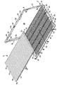
これより図面を参照するが、いくつかの図面を通して、類似の参照番号は類似または対応する部分を表しており、図1〜5は、ベース4と、場合により使用されるカバー6とを含む再利用可能なフィルタフレーム2を示しており、ベース4中に適合するのに適切な大きさおよび構成を有する着脱自在で自己隔置性のひだ付きフィルタ8とともに使用される。あるいは、フィルタ8をカバー6中に配置し、ベース4をカバー6に接近させるように、ベース4とカバー6との機能を交換することもできる。フィルタフレーム2は、ほぼ平面の長方形の形状を有し、住宅用空気処理システムの空気ダクトまたは暖房炉中での使用に特に適している。
Reference is now made to the drawings, wherein like reference numerals represent like or corresponding parts throughout the several views, and FIGS. 1-5 include a base 4 and
一般にフィルタ8は、複数のひだ12を有するろ過媒体10を含む。フィルタ8については、図6〜9を参照しながらより詳細に後述する。
Generally, the filter 8 includes a
ベース4およびカバー6は、周囲構造4a、6aをそれぞれ含み、これらは対応する第1の端部16、18および第2の端部20、22と、第1の側部24、26および第2の側部28、30とをそれぞれ有する。複数の等間隔の横方向リブ32は、ベース4の第1の側部24から、ベース4の第2の側部28まで延在しており、伸長したひだ12とかみ合って、ろ過媒体10のさらなる支持体となり、設置後および使用中にひだ12を均一な間隔に維持する。各ひだ12で完全で均一な間隔を得るために、ベース4は、成形方法の一端として必要となりうる不連続部分を除けば幅全体にわたってリブ32が連続することが望ましく、一様な高さを有することが望ましい。さらに、各下流ひだ開口部中に1つのリブ32が配列されるように、リブ32の数は、フィルタ8の下流側上のひだ12の数に対応することが好ましい。リブ32は、ベース4の周囲構造4aとともに成形することができるし、あるいはベース4の周囲構造4aに取り付けられるワイヤ、ダウエル、またはその他の部材として提供することもできる。
The base 4 and the
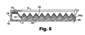
ベース4は、場合により、第1の端部16から第2の端部20まで延在し、横方向リブ32と組み合わされて格子構造を形成する複数の長手方向のレール34も含む。リブ32およびレール34は、独立した構造、または単一の構造として形成することができる。レール34は、場合により、フィルタひだ12の外形にほぼ従う三角形のスペーサー部分34a(図2)を有するように示されており、これによってひだ12の隔置された構造が維持される。各スペーサー部分34aは、レール34に沿ったベース36と、対応するリブ32と隣接する頂点37(図5)とを含む。リブ32およびレール34は、好ましくはABS(アクリロニトリルブタジエンスチレン)またはHIPS(高衝撃ポリスチレン)などの合成プラスチック材料で形成されるが、ワイヤまたは平坦な金属製フィンなどの他の従来材料で形成されてもよい。
Base 4 optionally also includes a plurality of
カバー6は、フレーム2からフィルタ8に空気が流れるようにするための中央開口部38を含み、これによって汚染物質を気流から除去することができる。カバー6をベース4の周囲と係合させることで、フィルタ8がフレーム2内に確実に維持され、フィルタ8のまわりに空気が流れるのが防止される。可撓性ストラップの形態の丁番部材40(図4)によって、ベース4およびカバー6は、それぞれの関連する第2の側部28、30に沿って枢着される。この方法では、フィルタ8をフレーム2内に設置したりフレーム2から取り外したりできるようにベース4およびカバー6のそれぞれの第1の側縁部24、26が配置される開放状態(図1)と、ベース4およびカバー6のそれぞれの第1の側縁部24、26が係合してフィルタ8がフレーム2中に閉じこめられる閉鎖状態(図4)との間でフレーム2が移動することができる。ベース4をカバー6と連結するためにあらゆる従来のヒンジを使用できることが理解できるであろう。あるいは、フレーム2は、射出成形などで形成された一体丁番によってベース4とカバー6とが連結される1枚の単体構造を有することもできる。ベース4およびカバー6は、たがいにかみ合うまたはその他の方法で連結する2つの独立した部品として形成されることも可能であることを理解されたい。
The
フレーム2を閉鎖状態に維持するため、場合により、位置合わせされた突起46(図1)の上にスナップ嵌めされる可撓性片持ち棒状部材44(図1)をそれぞれ有する1組の掛け金42(図4)が提供される。フック・ループ、ゴムバンド、錠などの他の従来のクロージャーまたはメカニカルファスナーを使用することもできる。
A set of
場合によりカバー6は、ろ過媒体10をフレーム内にさらに維持する機能を果たす、ベース4中に提供されているものと類似の横方向および/または長手方向の支持棒(図示せず)をさらに含むことができる。かかる支持棒は、空気ダクトにフレームを間違って逆方向に挿入した場合にろ過媒体10がフレームから膨らむのを防止する。逆方向に挿入されると、ひだがリブ32によって支持されず、そのため使用中につぶれやすくなるためフィルタは適切に機能しないが、ろ過媒体がフレーム2内に維持されることで、システムの損傷が回避される。
Optionally, the
空気ダクト内にフレーム2が正しく設置され、カバー6が上流となりベース4が下流となって、空気がカバー6、フィルタ8、およびベース4を続けて通過するようにするため、気流方向に対するフレームの適切な方向を示す視覚的標識47がフレーム2上に提供される。空気ダクト内でフレームを正しい方向にするためにさらに取扱説明書を提供することもできる。
To ensure that the
ベース4の第1の端部16および第2の端部20に提供される突起48は、フィルタ8をフレーム2内に設置する場合に、フィルタ8をベース4に取り付けるための固定機構として機能する。それぞれの突起48は、カバー6の第1の端部18および第2の端部22中に含まれる位置合わせされた孔50と連結する。他の好適な固定機構としては、接着剤、フック・ループファスナー、クリップ、クランプ、留め金、フックなどが挙げられる。あるいは、ベース4とカバー6との間にフィルタの端部を単純に捕捉または挟むことによってフィルタ8をフレーム2内に固定することができる。
The
一般に、フレーム2は、たとえば暖房炉、還気ダクト、窓用空調ユニット、または台所のレンジフードにおいて使用される住宅用エアフィルタのフレームとして意図されている。したがって、フレーム2は、一般に1/2インチ〜5インチ、好ましくは3/4インチ〜1 1/4インチの深さ、すなわち厚さを有し、より好ましくは約1インチの厚さを有する。フレーム2の高さは、一般に5インチ〜24インチの間であり、好ましくは10インチ〜20インチの間である。フレームの幅は、一般に10インチ〜40インチの間であり、好ましくは20インチ〜30インチの間である。
In general, the
フレーム2の空気ダクトへの設置および取り外しを容易にするため、ベース4の端部16、20およびカバー6の側部26にくぼみ52が提供される。このくぼみは、フレームの周囲に沿った狭い把持領域となり、設置および取り外しの作業中に使用者が容易につかむことができる。
In order to facilitate installation and removal of the
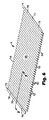
これより図6〜9を参照して、フィルタフレーム2内への配置に適合した交換可能な自己隔置性ひだ付きフィルタ挿入体8のさらなる詳細を示す。「自己隔置性」とは、一般に、二次間隔構造を使用することなく、等間隔に横方向リブ32を有するフレーム2内でフィルタ挿入体8が容易に伸長し配列される能力を意味する。ある態様においては、フィルタが均一に伸長する能力、またはフィルタが完全に折りたたまれた状態から伸長する傾向を意味する場合もある。ひだの均一な間隔とは、ひだがほぼ均等に伸長し、それによって隣接するひだ先端の間の距離がほぼ等しく、伸長したフィルタの全体の長さに沿って一定となることを意味する。本発明の別の態様においては、「自己隔置性」とは、自由に伸長できる場合に、完全に折りたたまれた長さの少なくとも500%まで伸長するひだ付きフィルタを意味する。
6-9, further details of the replaceable self-spaced pleated filter insert 8 adapted for placement in the
フィルタ8は、入口面54と出口面56とを有する可逆的に伸長可能および折りたたみ可能であるひだ付きろ過媒体10を含む。このフィルタは、リブ32を含まないフィルタフレームとともにフィルタが使用可能となる自立媒体で構成することができる。可逆的に伸長可能および折りたたみ可能な構造によって、輸送および保管のため圧縮形態にフィルタ8を折りたたむことができ、後にフレーム2中に配置し取り付けるために適切な長さまで伸長させることができる。この構造は、確実に均一なダウンウェブ間隔およびクロスウェブ安定性も得られ、このことはフィルタ8の取り扱いおよび設置に役立つ。
Filter 8 includes a
媒体10は、ひだ先端62を画定する折り目60をそれぞれ含む複数のひだ12と、1組の隣接するパネル64とを含む。連続するひだ先端62の間の間隔の長さ66はフィルタの大きさに依存するが、一般に約2ミリメートル〜約40ミリメートルの範囲である。しかしほとんどの用途では、連続するひだ先端62の間の間隔の長さ66は、好ましくは少なくとも5ミリメートルであり、より好ましくは少なくとも8ミリメートルである。ひだの深さおよびフィルタ10の厚さは、典型的には約1センチメートル〜約10センチメートル(0.4インチ〜4インチ)である。HVAC用途においては、フィルタ10の長さおよび幅は、典型的には30.5センチメートル×30.5センチメートル(12インチ×12インチ)から約50.8センチメートル×76.2センチメートル(20インチ×30インチ)である。
The medium 10 includes a plurality of
場合により、折り目60と平行なフィルタ8の対向する端部72、74に沿って細長い取り付け部材70が提供される。取り付け部材70は、好ましくはろ過媒体10の剛性よりも高い剛性を有する。取り付け部材70は、フィルタ8の端部72、74の剛性を増加させ、それによってフィルタ8の取り扱い性が改善され、フィルタ8がより容易かつ均一に伸長することができる。さらに、取り付け部材70は端部72、74の強度および剛性を増加させ、それによってフレーム2のベース4にフィルタ8を迅速かつ容易に取り付けることが可能となる。
Optionally, an
場合により、突起48(図1)と嵌合する孔76が取り付け部材70中に提供され、これらはフィルタ8をベース4に取り付け、フィルタ8をベース4内に配置した場合にフィルタ8を伸長状態に維持する機能を果たす。設置中にフレーム2内のフィルタ8を適切な方向にするために、一方向でのみフィルタ8をフレーム2に取り付けられるように非対称パターンで孔76および対応する突起48を提供することができる。ベース4とカバー6との間の取り付け部材70をはさむなど、フィルタ8をフレーム2に取り付けるための他の従来手段、フック・ループファスナー、接着剤、クリップ、クランプなどを使用することもできる。取り付け部材70は、金属箔、板紙、厚紙、チップボード、プラスチックフィルムなどの合成プラスチック材料、または互いに折り重ねられ積層されたろ過媒体の多層などのあらゆる好適な材料で形成されてよい。
Optionally, holes 76 are provided in the mounting
フィルタ挿入体8の構成に使用されるろ過媒体10は、比較的堅く、好ましくは自立型であり、静電気を帯電していてもよい。「自立型」とは、気流にさらされた場合にその形状をほぼ維持する媒体を意味する。したがって、媒体が自立型であるかどうかは、媒体自体の物理的性質、媒体の形状または構造、および特に最終用途において媒体がさらされる条件に依存する。
The
一般に、幅2インチおよび長さ1.5インチの試料サイズで50mgを超えるガーレー(Gurley)剛度を有する媒体、特に、このような試料サイズで100mgを超えるガーレー(Gurley)剛度を有する媒体が、典型的な住宅用途において自立型となる。この値未満の剛度を有する媒体の場合、その媒体が自立型となるかどうかは、その媒体の構造、および最終用途に依存する。媒体が自立型である場合は、気流にさらされても媒体がその形状を維持するので、支持リブ32(図1および2)が不要となる。しかし、ろ過媒体が自立型である場合にも、フィルタの安定性およびの全体性能を改善するために支持リブ32が提供されることが好ましい。
In general, media having a Gurley stiffness greater than 50 mg with a sample size of 2 inches wide and 1.5 inches long, especially media having a Gurley stiffness greater than 100 mg with such a sample size are typical. It becomes a self-supporting type in typical residential use. For media having a stiffness below this value, whether the media is self-supporting depends on the structure of the media and the end use. When the medium is a self-supporting type, the support rib 32 (FIGS. 1 and 2) is not necessary because the medium maintains its shape even when exposed to an air flow. However, it is preferred that
ひだ付きフィルタ挿入体8に固有の特徴によると、フレーム2の長さまで伸長するときには、フィルタ挿入体8は張力下にある。すなわち、ひだ付き構造はひだを互いに引っ張る傾向にあり、そのためフィルタはより短い長さに戻る。本発明の別の態様によると、完全に伸長した長さ(図8に示されている)の約80%を超える長さまでフィルタ挿入体8が伸長すると、フィルタ挿入体8が張力がかかり、フィルタ挿入体が取り外されその平衡長さまで戻る場合に、フィルタは完全に伸長した長さより短い長さに戻り、好ましくはフレーム2の長さ未満の長さに戻る。
According to the characteristic features of the pleated filter insert 8, the filter insert 8 is under tension when extended to the length of the
図8に示されるように、フィルタ挿入体が完全に伸長した長さとは、ひだがほぼ同一平面上にあり、フィルタ挿入体がほぼ平坦なシートの形態を取るようにフィルタ挿入体8が伸長した場合に実現される長さである。完全に伸長した長さを超えるまでフィルタ挿入体8を伸長させようとすると、ろ過媒体10自体に張力がかかり、最終的には媒体の引き裂きまたは破壊が生じる。
As shown in FIG. 8, the fully extended length of the filter insert is approximately coplanar and the filter insert 8 is extended so that the filter insert takes the form of a substantially flat sheet. The length realized in the case. Attempting to extend the filter insert 8 beyond the fully extended length will apply tension to the
たとえば、フィルタフレーム2の長さを超える長さまでフィルタ挿入体8を伸長させると、フィルタ挿入体8はある程度の弾性回復を示し、フィルタフレーム2の長さ未満の長さまで戻ろうとする。すなわち、フィルタ挿入体8は弱いばねのように挙動する。フィルタ挿入体8の構造は、均等かつ均一に伸長することもできる。さらに、フィルタ挿入体8は、フィルタ挿入体8の横方向の折りたたみまたはつぶれを阻止するのに十分なクロスウェブ安定性を有する。これらの特性のため、使用者がフィルタ挿入体8の端部を軽く動かして離したり近づけたりしてフレーム2の長さに合わせ、フレームのリブ32が存在する場合にはその間隔に使用者がひだを送り込むことによるフィルタ挿入体8をフレーム2内への設置が容易になる。
For example, when the filter insert 8 is extended to a length exceeding the length of the
別の態様において、フィルタ挿入体8が垂直に配列され、その完全に伸長した長さまで伸長されて、解放されると、フィルタ挿入体8は完全に伸長した長さの80%以下の長さに戻る。フィルタ挿入体8がその完全に折りたたまれた長さ(図9に示されている)まで折りたたまれ、続いて自由に伸長させると、フィルタ挿入体8は完全に折りたたまれた長さより400%長く伸長する。完全に折りたたまれた状態では、フィルタ挿入体8隣接するひだが向かい合って完全に接触し、重なり合った状態になる。 In another aspect, when the filter insert 8 is vertically aligned, extended to its fully extended length and released, the filter insert 8 is no longer than 80% of its fully extended length. Return. When the filter insert 8 is folded to its fully folded length (shown in FIG. 9) and subsequently freely extended, the filter insert 8 extends 400% longer than the fully folded length. To do. In the fully folded state, the filter insert 8 is adjacent to the adjacent pleats, making complete contact, and overlapping.
ひだ付きの場合に所望の性質を有するフィルタ挿入体を製造するために使用可能である限り、フィルタ挿入体8のために選択される個々のろ過媒体は本発明において重要ではない。フィルタ挿入体8、ポリプロピレン、線状ポリエチレン、およびポリ塩化ビニルなどの熱可塑性材料または熱硬化性材料で形成される不織繊維媒体などから作製することができる。フィルタ挿入体8は一般に、坪量が50〜80g/m2であり、引張強度が57〜95ポンド(253〜423N)であり、引張伸びが60%を超え、厚さが0.5〜0.63mmであり、孔径が212μmを超える。さらに、所望の弾力性を有するひだ付きフィルタを製造するために、ヒートセットによってひだを形成することができる。ヒートセットは、フィルタ挿入体8のひだ付き構造の張力または堅さを増加させることが分かっており、これは、ある種の媒体を使用する場合には望ましいこともある。 The individual filtration media selected for the filter insert 8 is not critical in the present invention as long as it can be used to produce a filter insert having the desired properties when pleated. It can be made from filter insert 8, polypropylene, linear polyethylene, and non-woven fiber media formed of thermoplastic or thermosetting materials such as polyvinyl chloride. The filter insert 8 generally has a basis weight of 50-80 g / m 2 , a tensile strength of 57-95 pounds (253-423N), a tensile elongation of over 60%, and a thickness of 0.5-0. .63 mm and the hole diameter exceeds 212 μm. Further, the pleats can be formed by heat setting to produce a pleated filter having the desired elasticity. Heat setting has been found to increase the tension or stiffness of the pleated structure of the filter insert 8, which may be desirable when using certain media.
好適なフィルタ挿入体8は、英国グウェント(Gwent)のテラム・リミテッド(Terram Limited)より入手可能なポリプロピレン繊維不織媒体であるBBSメルファブ80(BBS Melfab 80)媒体を使用して製造することができる。フィルタ挿入体8は、メルファブ80(Melfab 80)媒体にひだをつけ、次にそのひだをヒートセットさせることによって作製することができる。ヒートセットによるひだの形成は、ラボフスキー(Rabofsky)プリーツ機を200°Fのヒートセットプラテン温度で使用することによって実施することができる。ヒートセットによってこの媒体中にひだを形成することで、所望の特性を有するフィルタ挿入体が得られた。すなわち、このフィルタ挿入体8は自己隔置性となり所望の弾力性を有し、フィルタ挿入体8をフィルタフレーム2の長さまで伸長させると、フィルタ挿入体8に張力がかかった。したがって、フィルタフレーム2の長さより長くなるまでフィルタ挿入体8を伸長させると、フィルタ挿入体8は弾性回復を示し、そのためフィルタフレーム2の長さ未満の長さに戻ろうとする傾向を示した。
A suitable filter insert 8 can be manufactured using BBS Melfab 80 media, a polypropylene fiber nonwoven media available from Terram Limited of Gwent, UK. . The filter insert 8 can be made by pleating Melfab 80 media and then heat setting the pleats. The pleat formation by heat setting can be performed by using a Labofsky pleating machine at a heat set platen temperature of 200 ° F. Filter inserts with the desired properties were obtained by forming pleats in this medium by heat setting. That is, the filter insert 8 is self-spaced and has a desired elasticity, and when the filter insert 8 is extended to the length of the
メルファブ80(Melfab 80)はポリプロピレン繊維で形成される不織繊維媒体である。この媒体は、厚さが約0.63mmであり、坪量が80g/m2であり、透過性が690cfmである。このひだ付きフィルタ挿入体は、300fpmの面速度における圧力低下が0.13”W.Gとなり、500fpmの面速度における圧力低下が0.28W.G.となった。 Melfab 80 is a nonwoven fibrous medium formed from polypropylene fibers. This medium has a thickness of about 0.63 mm, a basis weight of 80 g / m 2 and a permeability of 690 cfm. This pleated filter insert had a pressure drop at a surface speed of 300 fpm was 0.13 "WG and a pressure drop at a surface speed of 500 fpm was 0.28 WG.
フィルタ8をフレーム2内に設置するため、ベース4がカバー6の下になるようにフレーム2をある表面上に置く。次に、掛け金44をはずし、ベース4から上方に離れるようにカバー6を旋回させることによって、図1に示されるようにフレーム2を開く。次に、取り付け部材70をつかみ、ひだに間隔が開くようにそれらの引き離すことによって、フィルタ8を伸長させる。次に、ひだ12がリブ32の間とかみ合うように、フィルタ8をベース4内に配置する。次に取り付け部材70中の孔76を突起48上に配置して、フィルタ8をベース4に取り付ける。次に、カバー6を閉じて、フィルタ8をその場所に維持し、掛け金44を再び閉じて、カバーをベース4と固定する。この方法の構成では、媒体10が裏側から支持され、これによって、フィルタ8を交換するときには、媒体の汚れた側が上方を向くので、そのため汚れが少なくてすむ。上記ステップを逆にすることで、フィルタ8がフレーム2から取り外される。
In order to install the filter 8 in the
ベース4ではなくカバー6にフィルタ8を取り付けることも可能であることは理解できるであろう。この場合、フレーム2を閉じるときにリブ32をひだ12の中まで動かす。しかしこれは、適切にリブ32を入れるためにひだをある程度調整する必要があり、交換中、汚れたフィルタは、汚れた側を下に置くことになるので、あまり望ましくない。この場合には、これによって望ましくない汚れが生じる。
It will be understood that the filter 8 can be attached to the
上記の本発明の概念から逸脱しない種々の変形および修正を行うことが可能であることは当業者には明らかであろう。したがって、本発明の範囲は、本出願に記載される構造に限定されるべきではなく、特許請求の範囲の文言によって記載される構造およびそれらの構造の同等物によってのみ限定されるべきである。 It will be apparent to those skilled in the art that various modifications and variations can be made without departing from the above inventive concept. Accordingly, the scope of the invention should not be limited to the structures described in this application, but only by the structures described by the language of the claims and the equivalents of those structures.
Claims (20)
前記ひだ付きフィルタ挿入体は、複数のひだを含む可逆的に折りたたみ可能および伸長可能なろ過媒体を含み、前記ひだ付きフィルタ挿入体が前記フィルタフレームの前記長さまで伸長されると、前記ひだ付きフィルタ挿入体に張力がかかり、それにより、前記ひだ付きフィルタ挿入体が解放されると、前記フレームの前記長さ以下の平衡長さに戻る傾向がある自己隔置性ひだ付きフィルタ挿入体。 A self-spaced pleated filter insert for use with a frame having a length, comprising:
The pleated filter insert includes a reversibly foldable and extensible filtration medium that includes a plurality of pleats, and the pleated filter insert when the pleated filter insert is extended to the length of the filter frame. A self-spaced pleated filter insert that tends to return to an equilibrium length less than or equal to the length of the frame when the insert is tensioned, thereby releasing the pleated filter insert.
前記ひだ付きフィルタ挿入体が、完全に伸長した長さを有し、前記ひだ付きフィルタ挿入体が、前記完全に伸長した長さの80%を超えて伸長されると、前記ひだ付きフィルタ挿入体に張力がかかり、そのため、前記ひだ付きフィルタ挿入体が解放されると、前記ひだ付きフィルタ挿入体が前記伸長した長さ未満の長さに戻る自己隔置性ひだ付きフィルタ挿入体。 A self-separating pleated filter insert comprising a reversibly foldable and extensible filtration medium comprising a plurality of pleats and including a fold defining each pleat tip and a set of adjacent panels. ,
The pleated filter insert has a fully extended length, and the pleated filter insert when the pleated filter insert is extended more than 80% of the fully extended length. A self-spaced pleated filter insert in which the pleated filter insert returns to a length less than the extended length when the pleated filter insert is released.
前記ひだ付きフィルタ挿入体は、ポリプロピレン繊維で形成される可逆的に折りたたみ可能および伸長可能なろ過媒体を含み、前記ひだ付きフィルタ挿入体は複数のひだを含み、前記ひだ付きフィルタ挿入体が伸長されると、前記ひだが均一に伸長し、さらに、前記ひだ付きフィルタ挿入体が前記フィルタフレームの前記長さまで伸長されると、前記ひだ付きフィルタ挿入体に張力がかかり、前記フレームの前記長さ以下の平衡長さに戻る傾向がある自己隔置性ひだ付きフィルタ挿入体。
A self-separating pleated filter insert for use with a reusable frame having a length comprising:
The pleated filter insert includes a reversibly foldable and extensible filtration media formed of polypropylene fiber, the pleated filter insert includes a plurality of pleats, and the pleated filter insert is elongated. Then, the pleats extend uniformly, and when the pleated filter insert is extended to the length of the filter frame, tension is applied to the pleated filter insert and is less than or equal to the length of the frame Self-separating pleated filter insert that tends to return to its equilibrium length.
Applications Claiming Priority (2)
| Application Number | Priority Date | Filing Date | Title |
|---|---|---|---|
| US10/746,832 US7150774B2 (en) | 2003-12-24 | 2003-12-24 | Self-spacing pleated filter insert |
| PCT/US2004/042463 WO2005065804A1 (en) | 2003-12-24 | 2004-12-16 | Self-spacing pleated filter insert |
Publications (2)
| Publication Number | Publication Date |
|---|---|
| JP2007516830A true JP2007516830A (en) | 2007-06-28 |
| JP2007516830A5 JP2007516830A5 (en) | 2008-01-31 |
Family
ID=34700676
Family Applications (1)
| Application Number | Title | Priority Date | Filing Date |
|---|---|---|---|
| JP2006547167A Withdrawn JP2007516830A (en) | 2003-12-24 | 2004-12-16 | Self-separating pleated filter insert |
Country Status (9)
| Country | Link |
|---|---|
| US (1) | US7150774B2 (en) |
| EP (1) | EP1697021A1 (en) |
| JP (1) | JP2007516830A (en) |
| KR (1) | KR20060126731A (en) |
| CN (1) | CN1898006A (en) |
| CA (1) | CA2550710C (en) |
| MX (1) | MXPA06007214A (en) |
| TW (1) | TW200528172A (en) |
| WO (1) | WO2005065804A1 (en) |
Cited By (1)
| Publication number | Priority date | Publication date | Assignee | Title |
|---|---|---|---|---|
| US9841730B2 (en) | 2015-06-24 | 2017-12-12 | Canon Kabushiki Kaisha | Filter frame and filter assembly |
Families Citing this family (53)
| Publication number | Priority date | Publication date | Assignee | Title |
|---|---|---|---|---|
| US7571721B2 (en) * | 2005-09-14 | 2009-08-11 | Franklin Machines Products | Baffle-type grease filter for kitchen ventilators |
| US7837756B2 (en) * | 2007-04-05 | 2010-11-23 | Aaf-Mcquay Inc. | Filter with ePTFE and method of forming |
| US7951229B2 (en) * | 2007-09-11 | 2011-05-31 | Columbus Industries, Inc. | Air filter formed from slit and expanded layers of electrostatically enhanced material |
| CL2008002533A1 (en) * | 2007-10-20 | 2009-10-09 | Porous Media Corp | A filter assembly comprising a hollow casing open at least at one end at least one closure member that closes the at least one end, the removable closure member being, at least one tubular plate, one or plus holes or openings, an inlet bimpellent chamber formed in the hollow housing |
| US20090188856A1 (en) * | 2007-10-20 | 2009-07-30 | Robb Benson | Externally Centering Filter Element or Cartridge and Housing and System Utilizing the Same |
| US20090183477A1 (en) * | 2008-01-23 | 2009-07-23 | Workman Roger L | Air filter |
| US7581539B2 (en) * | 2008-01-31 | 2009-09-01 | Franklin Machine Products | Baffle-type grease filters for kitchen ventilators |
| US8673040B2 (en) | 2008-06-13 | 2014-03-18 | Donaldson Company, Inc. | Filter construction for use with air in-take for gas turbine and methods |
| US7959700B2 (en) * | 2008-07-01 | 2011-06-14 | Mann + Hummel Gmbh | Filter orientation ribs |
| US8906275B2 (en) | 2012-05-29 | 2014-12-09 | Nike, Inc. | Textured elements incorporating non-woven textile materials and methods for manufacturing the textured elements |
| US8850719B2 (en) | 2009-02-06 | 2014-10-07 | Nike, Inc. | Layered thermoplastic non-woven textile elements |
| US9682512B2 (en) | 2009-02-06 | 2017-06-20 | Nike, Inc. | Methods of joining textiles and other elements incorporating a thermoplastic polymer material |
| US20100199406A1 (en) | 2009-02-06 | 2010-08-12 | Nike, Inc. | Thermoplastic Non-Woven Textile Elements |
| US20100314333A1 (en) * | 2009-06-10 | 2010-12-16 | Hollingsworth & Vose Company | Flutable fiber webs with low surface electrical resistivity for filtration |
| US8236082B2 (en) | 2009-06-19 | 2012-08-07 | Hollingsworth & Vose Company | Flutable fiber webs with high dust holding capacity |
| US8083828B2 (en) * | 2009-06-19 | 2011-12-27 | Hollingsworth & Vose Company | Fiber web having a high stiffness |
| WO2011137367A1 (en) * | 2010-04-30 | 2011-11-03 | Diversitech Corporation | Three-dimensional filter |
| WO2012071026A1 (en) * | 2010-11-23 | 2012-05-31 | Challen Sullivan | Direct replacement air filter with automatic filter media advance and wireless communications |
| US8828111B2 (en) | 2011-03-07 | 2014-09-09 | Field Controls, Llc | Collapsible filter |
| US9452374B2 (en) | 2011-09-20 | 2016-09-27 | Clarification Technology, Inc. | Filtration device for cooking oil |
| CN104039419B (en) | 2012-01-13 | 2017-02-08 | 曼·胡默尔有限公司 | Air filter element having specific retaining geometry |
| US20130255103A1 (en) | 2012-04-03 | 2013-10-03 | Nike, Inc. | Apparel And Other Products Incorporating A Thermoplastic Polymer Material |
| CN102836783B (en) * | 2012-10-09 | 2014-08-27 | 戴若夫 | Electrostatic dust collector with variable inter-electrode space |
| US8992650B2 (en) * | 2012-10-19 | 2015-03-31 | American Air Filter Company, Inc. | Air filter with tensile support member |
| CN105209147B (en) | 2013-03-15 | 2020-07-03 | 唐纳森公司 | Filter media and elements |
| US9474994B2 (en) | 2013-06-17 | 2016-10-25 | Donaldson Company, Inc. | Filter media and elements |
| USD706577S1 (en) * | 2013-08-29 | 2014-06-10 | Bsh Home Appliances Corporation | Cooking grill |
| WO2016032933A1 (en) * | 2014-08-25 | 2016-03-03 | 3M Innovative Properties Company | Adjustable air filter |
| USD763542S1 (en) * | 2015-02-05 | 2016-08-16 | Mafin S.P.A. | Snack |
| US10335724B1 (en) * | 2015-03-31 | 2019-07-02 | Ertec Environmental Systems Llc | Filter and barrier |
| GB201505684D0 (en) * | 2015-04-01 | 2015-05-13 | Mobiair Pte Ltd | Low-energy next generation hybrid filtration technology |
| WO2017053341A1 (en) | 2015-09-24 | 2017-03-30 | 3M Innovative Properties Company | Expandable air filters |
| US10940416B2 (en) | 2015-09-24 | 2021-03-09 | 3M Innovative Properties Company | Air filter devices with gap sealing unit |
| US11014030B2 (en) | 2016-02-17 | 2021-05-25 | Hollingsworth & Vose Company | Filter media including flame retardant fibers |
| US10252200B2 (en) | 2016-02-17 | 2019-04-09 | Hollingsworth & Vose Company | Filter media including a filtration layer comprising synthetic fibers |
| US10213721B2 (en) * | 2016-04-28 | 2019-02-26 | Cory Elliott | Air filter arrangement |
| CN105806645A (en) * | 2016-05-10 | 2016-07-27 | 北京交通大学 | Driven sampling device for organic pollutants of water and bottom mud and use method thereof |
| USD972698S1 (en) * | 2016-06-20 | 2022-12-13 | 3M Innovative Properties Company | Air filter |
| JP6642461B2 (en) * | 2017-01-17 | 2020-02-05 | トヨタ自動車株式会社 | Battery cooling device |
| USD804898S1 (en) * | 2017-06-26 | 2017-12-12 | E. Mishan & Sons, Inc. | Smokeless grill |
| CN109578178B (en) * | 2017-09-29 | 2020-08-04 | 上海汽车集团股份有限公司 | Automobile, air filter and control system thereof |
| EP3692550A4 (en) * | 2017-10-06 | 2021-06-02 | Candu Energy Inc. | Method and apparatus for filtering fluid in nuclear power generation |
| USD859061S1 (en) | 2019-01-31 | 2019-09-10 | E. Mishan & Sons, Inc. | Smokeless grill |
| USD883018S1 (en) | 2019-01-31 | 2020-05-05 | E. Mishan & Sons, Inc. | Smokeless grill |
| USD883020S1 (en) | 2019-01-31 | 2020-05-05 | E. Mishan & Sons, Inc. | Smokeless grill |
| USD883019S1 (en) | 2019-01-31 | 2020-05-05 | E. Mishan & Sons, Inc. | Smokeless grill |
| US11859891B2 (en) | 2019-07-17 | 2024-01-02 | Electrolux Home Products, Inc. | Appliance air freshener |
| USD950698S1 (en) * | 2019-09-09 | 2022-05-03 | Cleanair.Ai Corporation | Filter assembly |
| US11566796B2 (en) | 2019-12-10 | 2023-01-31 | Lg Electronics Inc. | Air management apparatus and method thereof |
| DE102020110596A1 (en) | 2020-04-17 | 2021-10-21 | Bayerische Motoren Werke Aktiengesellschaft | Filters, a method for producing a filter and a motor vehicle with such a filter |
| US11745131B2 (en) * | 2020-06-29 | 2023-09-05 | Omachron Intellectual Property Inc. | Filter assembly |
| USD973301S1 (en) * | 2021-01-25 | 2022-12-27 | Spectrum Brands, Inc. | Textured sheet pet treat |
| FR3140555A1 (en) * | 2022-10-11 | 2024-04-12 | Sogefi Filtration | AIR FILTRATION DEVICE WITH ADSORPTION PRODUCT AND ASSEMBLY METHOD |
Family Cites Families (34)
| Publication number | Priority date | Publication date | Assignee | Title |
|---|---|---|---|---|
| US2074294A (en) * | 1935-11-16 | 1937-03-16 | American Radiator Co | Filter |
| US2907408A (en) * | 1956-05-18 | 1959-10-06 | Cambridge Filter Mfg Corp | Filter construction |
| US3280984A (en) | 1964-06-15 | 1966-10-25 | American Air Filter Co | Filter pad and support means therefor |
| US3853529A (en) * | 1971-06-09 | 1974-12-10 | Farr Co | Pleated air filter cartridge |
| US3774377A (en) | 1972-04-21 | 1973-11-27 | American Air Filter Co | Filter assembly with replaceable filter element |
| US3789589A (en) | 1973-02-28 | 1974-02-05 | Res Prod Corp | High performance filter assembly |
| US4042358A (en) | 1976-05-14 | 1977-08-16 | Research Products Corporation | Filter media |
| US4135900A (en) * | 1977-05-31 | 1979-01-23 | American Air Filter Company, Inc. | Gas filter device |
| US4334899A (en) | 1981-04-09 | 1982-06-15 | Mcconnell Paul A | Snap filter grill and assembly |
| US4363643A (en) * | 1981-10-16 | 1982-12-14 | Emerson Electric Co. | Support means for filter material in a non-electric air cleaner |
| US4547950A (en) * | 1984-05-29 | 1985-10-22 | Honeywell Inc. | Method of spacing the folds of a folded filter media |
| CH678154A5 (en) | 1989-04-26 | 1991-08-15 | Robert Andreae | |
| US5066400A (en) | 1990-10-09 | 1991-11-19 | Donaldson Company, Inc. | Self-spaced pleated filter |
| US5501794A (en) | 1991-12-31 | 1996-03-26 | Minnesota Mining And Manufacturing Company | Wave filter with flexible tensioning members |
| DE4206738A1 (en) | 1992-03-04 | 1993-09-09 | Minnesota Mining & Mfg | FILTER ELEMENT FOR FILTERING FLUIDS, IN PARTICULAR FOR FILTERING AIR |
| US5273564A (en) * | 1992-12-24 | 1993-12-28 | Research Products Corporation | One piece filter media framework |
| US5458772A (en) * | 1994-01-13 | 1995-10-17 | Filtercorp Partners L.P. | Adjustable filter holder assembly |
| DE4433129A1 (en) | 1994-09-16 | 1996-03-28 | Gore W L & Ass Gmbh | Process for the production of a filter medium |
| US5709735A (en) | 1995-10-20 | 1998-01-20 | Kimberly-Clark Worldwide, Inc. | High stiffness nonwoven filter medium |
| US5792242A (en) * | 1996-02-26 | 1998-08-11 | Minnesota Mining And Manufacturing Co. | Electrostatic fibrous filter web |
| US5667562A (en) * | 1996-04-19 | 1997-09-16 | Kimberly-Clark Worldwide, Inc. | Spunbond vacuum cleaner webs |
| US5743927A (en) * | 1996-07-31 | 1998-04-28 | Donaldson Company, Inc. | Air filter element; assembly; and, method |
| CA2210950A1 (en) | 1996-07-31 | 1998-01-31 | Richard J. Osendorf | Air filter element; assembly; and method |
| FR2752294B1 (en) | 1996-08-12 | 1998-11-27 | Lorraine Laminage | METHOD AND DEVICE FOR CONTINUOUS MEASUREMENT OF INSULATING COATING THICKNESS |
| US6033453A (en) * | 1997-01-30 | 2000-03-07 | Weddell, Iii; Robert W. | Re-usable frame support rack for replaceable pleated-media filter core |
| US5871836A (en) * | 1997-08-27 | 1999-02-16 | Airflo Europe N.V. | Composite pleated fibrous structures containing split film fibers |
| US6120633A (en) * | 1999-03-04 | 2000-09-19 | Hrs Textiles, Inc. | Method of fabricating a self pleating filter media |
| US6521011B1 (en) | 1999-07-15 | 2003-02-18 | 3M Innovative Properties Company | Self-supporting pleated filter and method of making same |
| US6258143B1 (en) * | 1999-07-15 | 2001-07-10 | Dana Corporation | Fluid filter with baffle |
| US6585793B2 (en) * | 2000-12-29 | 2003-07-01 | Andreae Filters, Inc. | Filter apparatus and methods |
| US6599343B2 (en) * | 2001-10-09 | 2003-07-29 | Carrier Corporation | Method and apparatus for assembling an expandable and disposable media filter |
| US6740137B2 (en) * | 2002-06-14 | 2004-05-25 | 3M Innovative Properties Company | Collapsible pleated filter element |
| US6860916B2 (en) * | 2002-06-14 | 2005-03-01 | 3M Innovative Properties Company | Filter assembly |
| US6843820B2 (en) * | 2003-03-04 | 2005-01-18 | 3M Innovative Properties Company | Filter assembly |
-
2003
- 2003-12-24 US US10/746,832 patent/US7150774B2/en not_active Expired - Lifetime
-
2004
- 2004-12-16 WO PCT/US2004/042463 patent/WO2005065804A1/en active Application Filing
- 2004-12-16 JP JP2006547167A patent/JP2007516830A/en not_active Withdrawn
- 2004-12-16 KR KR1020067014671A patent/KR20060126731A/en not_active Application Discontinuation
- 2004-12-16 CA CA2550710A patent/CA2550710C/en not_active Expired - Fee Related
- 2004-12-16 EP EP04814619A patent/EP1697021A1/en not_active Withdrawn
- 2004-12-16 MX MXPA06007214A patent/MXPA06007214A/en not_active Application Discontinuation
- 2004-12-16 CN CNA2004800391029A patent/CN1898006A/en active Pending
- 2004-12-23 TW TW093140284A patent/TW200528172A/en unknown
Cited By (1)
| Publication number | Priority date | Publication date | Assignee | Title |
|---|---|---|---|---|
| US9841730B2 (en) | 2015-06-24 | 2017-12-12 | Canon Kabushiki Kaisha | Filter frame and filter assembly |
Also Published As
| Publication number | Publication date |
|---|---|
| US7150774B2 (en) | 2006-12-19 |
| KR20060126731A (en) | 2006-12-08 |
| CN1898006A (en) | 2007-01-17 |
| MXPA06007214A (en) | 2006-09-04 |
| TW200528172A (en) | 2005-09-01 |
| CA2550710C (en) | 2012-10-02 |
| CA2550710A1 (en) | 2005-07-21 |
| WO2005065804A1 (en) | 2005-07-21 |
| EP1697021A1 (en) | 2006-09-06 |
| US20050138906A1 (en) | 2005-06-30 |
Similar Documents
| Publication | Publication Date | Title |
|---|---|---|
| JP2007516830A (en) | Self-separating pleated filter insert | |
| CA2550860C (en) | Filter assembly with self-spacing pleated filter | |
| US6955702B2 (en) | Filter frame | |
| US6860916B2 (en) | Filter assembly | |
| US6740137B2 (en) | Collapsible pleated filter element | |
| CN107405559B (en) | Conformable pleated air filter with bridging filaments | |
| US6843820B2 (en) | Filter assembly | |
| EP0620755B1 (en) | Filter system for filtering fluids | |
| US5639287A (en) | Filter system for filtering fluids | |
| JP2007516830A5 (en) | ||
| WO2018128990A1 (en) | Universal air filters |
Legal Events
| Date | Code | Title | Description |
|---|---|---|---|
| A521 | Written amendment |
Free format text: JAPANESE INTERMEDIATE CODE: A523 Effective date: 20071206 |
|
| A621 | Written request for application examination |
Free format text: JAPANESE INTERMEDIATE CODE: A621 Effective date: 20071206 |
|
| A761 | Written withdrawal of application |
Free format text: JAPANESE INTERMEDIATE CODE: A761 Effective date: 20080718 |