JP2007513360A - Improvement of color ratio in 3D image display - Google Patents
Improvement of color ratio in 3D image display Download PDFInfo
- Publication number
- JP2007513360A JP2007513360A JP2006530952A JP2006530952A JP2007513360A JP 2007513360 A JP2007513360 A JP 2007513360A JP 2006530952 A JP2006530952 A JP 2006530952A JP 2006530952 A JP2006530952 A JP 2006530952A JP 2007513360 A JP2007513360 A JP 2007513360A
- Authority
- JP
- Japan
- Prior art keywords
- color
- pixels
- image
- pixel
- group
- Prior art date
- Legal status (The legal status is an assumption and is not a legal conclusion. Google has not performed a legal analysis and makes no representation as to the accuracy of the status listed.)
- Pending
Links
Images


Classifications
-
- H—ELECTRICITY
- H04—ELECTRIC COMMUNICATION TECHNIQUE
- H04N—PICTORIAL COMMUNICATION, e.g. TELEVISION
- H04N13/00—Stereoscopic video systems; Multi-view video systems; Details thereof
- H04N13/30—Image reproducers
- H04N13/302—Image reproducers for viewing without the aid of special glasses, i.e. using autostereoscopic displays
- H04N13/31—Image reproducers for viewing without the aid of special glasses, i.e. using autostereoscopic displays using parallax barriers
-
- G—PHYSICS
- G09—EDUCATION; CRYPTOGRAPHY; DISPLAY; ADVERTISING; SEALS
- G09G—ARRANGEMENTS OR CIRCUITS FOR CONTROL OF INDICATING DEVICES USING STATIC MEANS TO PRESENT VARIABLE INFORMATION
- G09G3/00—Control arrangements or circuits, of interest only in connection with visual indicators other than cathode-ray tubes
- G09G3/001—Control arrangements or circuits, of interest only in connection with visual indicators other than cathode-ray tubes using specific devices not provided for in groups G09G3/02 - G09G3/36, e.g. using an intermediate record carrier such as a film slide; Projection systems; Display of non-alphanumerical information, solely or in combination with alphanumerical information, e.g. digital display on projected diapositive as background
- G09G3/003—Control arrangements or circuits, of interest only in connection with visual indicators other than cathode-ray tubes using specific devices not provided for in groups G09G3/02 - G09G3/36, e.g. using an intermediate record carrier such as a film slide; Projection systems; Display of non-alphanumerical information, solely or in combination with alphanumerical information, e.g. digital display on projected diapositive as background to produce spatial visual effects
-
- H—ELECTRICITY
- H04—ELECTRIC COMMUNICATION TECHNIQUE
- H04N—PICTORIAL COMMUNICATION, e.g. TELEVISION
- H04N13/00—Stereoscopic video systems; Multi-view video systems; Details thereof
- H04N13/30—Image reproducers
- H04N13/302—Image reproducers for viewing without the aid of special glasses, i.e. using autostereoscopic displays
- H04N13/305—Image reproducers for viewing without the aid of special glasses, i.e. using autostereoscopic displays using lenticular lenses, e.g. arrangements of cylindrical lenses
-
- H—ELECTRICITY
- H04—ELECTRIC COMMUNICATION TECHNIQUE
- H04N—PICTORIAL COMMUNICATION, e.g. TELEVISION
- H04N13/00—Stereoscopic video systems; Multi-view video systems; Details thereof
- H04N13/30—Image reproducers
- H04N13/324—Colour aspects
-
- G—PHYSICS
- G09—EDUCATION; CRYPTOGRAPHY; DISPLAY; ADVERTISING; SEALS
- G09G—ARRANGEMENTS OR CIRCUITS FOR CONTROL OF INDICATING DEVICES USING STATIC MEANS TO PRESENT VARIABLE INFORMATION
- G09G2320/00—Control of display operating conditions
- G09G2320/02—Improving the quality of display appearance
- G09G2320/0242—Compensation of deficiencies in the appearance of colours
-
- G—PHYSICS
- G09—EDUCATION; CRYPTOGRAPHY; DISPLAY; ADVERTISING; SEALS
- G09G—ARRANGEMENTS OR CIRCUITS FOR CONTROL OF INDICATING DEVICES USING STATIC MEANS TO PRESENT VARIABLE INFORMATION
- G09G2320/00—Control of display operating conditions
- G09G2320/02—Improving the quality of display appearance
- G09G2320/0271—Adjustment of the gradation levels within the range of the gradation scale, e.g. by redistribution or clipping
-
- G—PHYSICS
- G09—EDUCATION; CRYPTOGRAPHY; DISPLAY; ADVERTISING; SEALS
- G09G—ARRANGEMENTS OR CIRCUITS FOR CONTROL OF INDICATING DEVICES USING STATIC MEANS TO PRESENT VARIABLE INFORMATION
- G09G2320/00—Control of display operating conditions
- G09G2320/06—Adjustment of display parameters
- G09G2320/068—Adjustment of display parameters for control of viewing angle adjustment
-
- G—PHYSICS
- G09—EDUCATION; CRYPTOGRAPHY; DISPLAY; ADVERTISING; SEALS
- G09G—ARRANGEMENTS OR CIRCUITS FOR CONTROL OF INDICATING DEVICES USING STATIC MEANS TO PRESENT VARIABLE INFORMATION
- G09G2354/00—Aspects of interface with display user
-
- G—PHYSICS
- G09—EDUCATION; CRYPTOGRAPHY; DISPLAY; ADVERTISING; SEALS
- G09G—ARRANGEMENTS OR CIRCUITS FOR CONTROL OF INDICATING DEVICES USING STATIC MEANS TO PRESENT VARIABLE INFORMATION
- G09G2360/00—Aspects of the architecture of display systems
- G09G2360/18—Use of a frame buffer in a display terminal, inclusive of the display panel
Abstract
視野角に応じて異なるビューが表示されるように3次元画像を表示する表示装置は、画像を表示する、複数の別々にアドレス可能な画素を有する表示パネルを有する。各画素は、グループ内の異なる画素が画像の異なるビューに対応するようにグループ化されている。各画素は、画像内の各物理的位置に関するカラークラスタで構成される。表示ドライバが、受け取った画像データに従って画像を生成するために各画素の透過特性を制御する。表示パネルの各画素に与えられる駆動信号は、見る方向に依存しない各クラスタに関する画像の色を生成するようにグループ内の各画素及びクラスタ内の各グループの光透過度を変える色補正値を用いて調節される。 A display device that displays a three-dimensional image so that different views are displayed according to a viewing angle has a display panel that displays a plurality of separately addressable pixels. Each pixel is grouped so that different pixels in the group correspond to different views of the image. Each pixel consists of a color cluster for each physical location in the image. A display driver controls the transmission characteristics of each pixel to generate an image according to the received image data. The drive signal given to each pixel of the display panel uses a color correction value that changes the light transmittance of each pixel in the group and each group in the cluster so as to generate an image color for each cluster that does not depend on the viewing direction. Adjusted.
Description
本発明は、表示装置に係り、特に3次元又は立体画像を表示する表示装置に関する。 The present invention relates to a display device, and more particularly to a display device that displays a three-dimensional or stereoscopic image.
3次元画像の生成は、一般に、表示装置が該表示装置のユーザの左右の目に異なるビューを与えることができることを要する。これは、特別に作られたゴーグルを使用することによってユーザのそれぞれの目に直接的に異なる画像を与えることにより実現され得る。1つの例では、ディスプレイがタイムシーケンシャルのやり方で右のビューと左のビューとを交互に与え、これらのビューは同期のとられるビューイングゴーグルにより見る人の対応する目に入る。対照的に、本発明は、画像の異なるビューが単一の表示パネルに対する視野角に応じて見られる表示装置の種類に関するものである。以下、これらは該して3次元表示装置と呼ばれる。 Generation of a three-dimensional image generally requires that the display device be able to give different views to the left and right eyes of the user of the display device. This can be achieved by giving a different image directly to each of the user's eyes by using specially made goggles. In one example, the display alternates between right and left views in a time-sequential manner, and these views enter the viewer's corresponding eyes with synchronized viewing goggles. In contrast, the present invention relates to a type of display device in which different views of an image can be viewed as a function of the viewing angle for a single display panel. These are hereinafter referred to as three-dimensional display devices.
そのような3次元表示装置の1つの既知の種類は、視差バリア法が実現された液晶ディスプレイである。そのようなシステムが図1に示されている。 One known type of such 3D display device is a liquid crystal display in which a parallax barrier method is realized. Such a system is shown in FIG.
図1を参照すると、視差バリアタイプの表示装置100は、複数の別個の光源を与えるバックパネル11を有している。図示されているように、バックパネル11は、表面全体にわたって分散する複数のスリット14aないし14dを有する不透明のマスク又はバリア層13により覆われた(フォトルミネセンスパネルのような)面光源12として形成され得る。この場合、上記スリット14のそれぞれは線光源の役割を果たす。
Referring to FIG. 1, a parallax barrier
液晶表示パネル(LCD)15は(例えば図1において1ないし10の参照符号が付された)複数の画素を有しており、これらはそれぞれの光透過特性を変化させるために既知の技術により電気的な信号によって別々にアドレス可能である。バックパネル11は、線光源14のそれぞれが画素のグループ16に対応するようにLCDパネル15に対して接近して配置されている。例えば、グループ161として示されている画素1ないし5はスリット14aに対応し、グループ162として示されている画素6ないし10はスリット14bに対応している等である。
The liquid crystal display panel (LCD) 15 has a plurality of pixels (for example, denoted by
画素のグループ16の各画素は、対応する線光源14aが当該ビューに対応する画素1ないし5の1つを介して見られるように画像の複数の可能なビュー(V−2,V−1,V0,V1,V2)のうちの1つのビューVに対応する。各グループ16の画素数は、存在する画像のビューの数を決定し、図示されている装置では5つである。ビューの数が大きくなるほど、3次元効果がよりリアルになり、より傾斜した視野角が与えられる。
Each pixel of
本明細書全体において、我々は表示パネルの全ての画素により生成される画像全体を表示される「画像」と呼んでおり、上記画像は特定の視野角により決定される複数の「ビュー」により構成される。 Throughout this specification, we refer to the entire image generated by all the pixels of the display panel as the displayed “image”, which consists of multiple “views” determined by a specific viewing angle. Is done.
上述の従来技術の装置には問題が存在する。上記LCDパネルの各画素の光透過係数は視野角に強く依存する。従って、全ての画素1ないし5が等しく駆動される場合、光源14aの見られる強度はそれぞれのビューに関して異なって現れる。例えば、V0はV2とは異なる。同様に、LCDパネル15の各画素の光透過係数は、色(すなわち、波長)に強く依存する。従って、上記光源の見られる強度はそれぞれの色に関して異なって現れる。
There are problems with the prior art devices described above. The light transmission coefficient of each pixel of the LCD panel strongly depends on the viewing angle. Thus, if all the
そのようなディスプレイは、3原色(例えばRGB)のそれぞれに異なる画素(及び異なる画素のグループ16)を与えることに依存するので、これらのアーチファクトは個々の色のレンダリングが視野角の関数として変化することを意味する。これは、画像の異なるビューを目にする際に、最適状態に及ばない画像及び望ましくない色のアーチファクトを招く。 Since such a display relies on providing different pixels (and different groups of pixels 16) for each of the three primary colors (eg RGB), these artifacts vary in the rendering of individual colors as a function of viewing angle. Means that. This leads to sub-optimal images and undesirable color artifacts when viewing different views of the image.
US2003/0052836公報には、カラー表示装置の前方に位置する複数のカラーフィルタを伴う特別に作られた遮光マスクを用いる3次元画像装置が説明されている。上記遮光マスクは、異なる視野角における3原色の輝度比を維持する役割を果たす。 US 2003/0052836 describes a three-dimensional image device using a specially made shading mask with a plurality of color filters located in front of the color display device. The shading mask serves to maintain the luminance ratio of the three primary colors at different viewing angles.
本発明の目的は、画像の異なるビューが視野角に応じて表示される3次元画像を表示する表示装置における望ましくない色のアーチファクトを克服又は緩和することにある。 It is an object of the present invention to overcome or mitigate undesirable color artifacts in display devices that display three-dimensional images in which different views of the image are displayed as a function of viewing angle.
1つの観点によれば、本発明は、視野角に応じて異なるビューが表示されるように3次元画像を表示する表示装置であって、上記画像を表示する、複数の別々にアドレス可能な画素を有する表示パネルであって、グループ内の異なる画素が上記画像の異なるビューに対応するように上記画素がグループ化された当該表示パネルと、受け取った画像データに従って画像を生成するために各画素の光学的特性を制御する表示ドライバと、上記光学的特性の所定の視野角依存性を補償するためにグループ内の少なくとも幾つかの画素の上記光学的特性を更に制御する色補償装置とを含む当該表示装置を提供する。 According to one aspect, the present invention is a display device that displays a three-dimensional image so that different views are displayed according to a viewing angle, and a plurality of separately addressable pixels that display the image. A display panel having the pixels grouped such that different pixels in the group correspond to different views of the image, and each pixel to generate an image according to the received image data. A display driver for controlling the optical characteristics and a color compensator for further controlling the optical characteristics of at least some of the pixels in the group to compensate for a predetermined viewing angle dependence of the optical characteristics. A display device is provided.
他の観点によれば、本発明は、視野角に応じて画像の異なるビューが表示されるように表示装置に3次元の上記画像を表示する方法であって、表示パネルにおいて複数の別々にアドレス可能な画素のそれぞれに関して画素データ値を形成するために画像データを処理するステップであって、上記画素は、グループ内の異なる画素が上記画像の異なるビューに対応するようにグループ化され、上記画素データ値は画像を生成するために対応する画素の光学的特性を制御する当該ステップと、上記光学的特性の所定の視野角依存性を補償するために各グループ内の少なくとも幾つかの画素データ値に色補正値を与えるステップと、上記画像を生成するように表示パネルの画素を駆動するため、補正された上記画素データ値を用いるステップとを含む当該方法を提供する。 According to another aspect, the present invention is a method for displaying the three-dimensional image on a display device so that different views of the image are displayed according to the viewing angle, and a plurality of separate addresses are displayed on the display panel. Processing image data to form pixel data values for each of the possible pixels, wherein the pixels are grouped such that different pixels in the group correspond to different views of the image; The data values are the step of controlling the optical characteristics of the corresponding pixels to produce an image, and at least some pixel data values in each group to compensate for the predetermined viewing angle dependence of the optical characteristics. And a step of using the corrected pixel data values to drive the pixels of the display panel to generate the image. Providing the method.
本発明の実施の形態が、添付の図面を参照して例として説明される。 Embodiments of the present invention will now be described by way of example with reference to the accompanying drawings.
図1を参照して、視差バリアタイプの3次元画像表示装置の基本的な機能は既に説明されている。表示パネル15及びバックパネル11の照明源の同様の構造が、本発明の好ましい実施の形態において用いられ得る。しかしながら、以下において明らかになるように他の構成が用いられてもよいことが理解されるであろう。
With reference to FIG. 1, the basic functions of the parallax barrier type three-dimensional image display device have already been described. Similar structures of the illumination sources of the
一般に、本発明は複数の別々にアドレス可能である画素1〜10を有する表示パネル15を用い、これらの画素はグループ161,162内の異なる画素1〜5又は6〜10がそれぞれ画像の異なるビューに対応するようにグループ化されている。表示パネル15は、各画素の光学的特性が電気的な制御信号により変化して画像を生成する任意の好適な電気光学装置であり得る。上記表示パネルは液晶ディスプレイであることが好ましい。
In general, the present invention uses a
複数の別個の光源14a〜14dを有する照明源は、画素の各グループ16が当該光源のうちの対応するものから光を受け取るように配置されて設けられていることが好ましい。これは、図1の面光源12及びマスク13の配列として存在し得るが、画素のライン、個々の画素又は画素のブロックとして光源14を与える画素化された光源としても設けられ得る。
An illumination source having a plurality of
更に、上記複数の別個の光源は、連続する高強度のライトスポットを与えるバックライト及びレンズアレイ(例えば、レンティキュラシートアレイ)として設けられる事実上の(virtual)光源であり得る。そのような構成は図7に示されている。表示装置80は、LCDパネル75と、面光源72と、レンズアレイ71とを含んでいる。図1と関連して説明されたものと同様に、上記レンズアレイは、それぞれが上記LCDパネルの複数の画素を照らすようLCDパネルの平面のわずかに外側の複数の別個の焦点73に面光源72からの光を集束させる。
Further, the plurality of separate light sources may be virtual light sources provided as a backlight and lens array (eg, a lenticular sheet array) that provides a continuous high intensity light spot. Such an arrangement is shown in FIG. The
図2aを参照すると、表示パネル15の画素の各グループ16は、画像における1つの物理的な空間的位置に対応している。各物理的な空間17に関して3つの分離して近接配置された画素のグループ16R,16G,16Bが存在し、1つのグループは各原色に関するものであり、それにより、既知のカラー表示技術に従って実効的な認識される色を当該物理的な位置に与える画素のクラスタ17が形成されている。
Referring to FIG. 2a, each
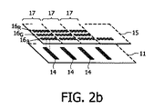
図2bに模式的に示されているように、上記表示装置は、各画素がそれらの間において共有される白色光源14のビューに特定の色及び強度を付与するために、ある波長の光を吸収又は反射する画素を含む表示パネル15を含み得る。その場合、カラークラスタ17の各画素のグループ16R,16G,16Bは、(例えば、表示パネルに適切なカラーフィルタを組み込むことにより)異なる波長において光を吸収するように選択される。
As schematically shown in FIG. 2b, the display device emits light of a certain wavelength in order to give a particular color and intensity to the view of the
代替として、図2aに示されているように、カラークラスタ17の画素の各グループ16は、可能な3つの異なる原色の光源のうちの1つを基準として配置され得る。従って、光源14Rは赤色であり、光源14Gは緑色であり、光源14Bは青色であり得る。その場合、画素のグループ16R,16G,16Bがカラークラスタ17を形成する。
Alternatively, as shown in FIG. 2a, each
表示パネル15における画素のグループの一部が図2cに示されている。幅wの光源14は、上記表示パネルの平面の法線に対してそれぞれの視野角φ0,φ1,…,φ7の画素のグループ0,…,7に対応しており、これらの画素を介して見られる。画素のグループ16の半分のみが図示されており、画素のグループ16を完全なものにするためには画素0の左側に更に7つの画素が存在することが理解されるであろう。
A part of the group of pixels in the
各画素は、幅p0,p1,…,p7を有している。各幅p0,…,p7は等しいことが好ましいが、通過する光の入射角をある程度補償するために異なっていることも可能である。バックパネルの照明源14と表示パネル15との距離は、hとして図示してされている。好ましい表示装置ではh=2.3mm、p0=200μm、w=50μmであるが、これらの値は大きく変化し得る。
Each pixel has a width p 0 , p 1 ,..., P 7 . Each width p 0 ,..., P 7 is preferably equal, but can also be different to compensate to some extent for the incident angle of light passing therethrough. The distance between the back
図3は、φ=0°の視野角(例えば画素0)に関する90°ねじれネマティックLCDの形態の表示パネル15についての透過度(T)対電圧(V)特性30を示している。赤色、緑色及び青色の波長の透過度に関する曲線が、曲線33,34,32としてそれぞれ示されている。第4の曲線31は、白色光を表しており、白色光をモデル化するための加重平均である。0ないし1Vの範囲の駆動電圧の下において動作する画素に関する光の透過係数は、波長によって約0.8と1.0との間で変動することに注意されたい。
FIG. 3 shows the transmission (T) versus voltage (V) characteristic 30 for a
図4は、φ=60°の視野角(例えば画素7)に関する90°ねじれネマティックLCDの形態の表示パネル15についての透過度(T)対電圧(V)特性40を示している。赤色、緑色及び青色の波長の透過度に関する曲線が、曲線43,44,42としてそれぞれ示されている。第4の曲線41は、白色光を表しており、白色光をモデル化するための加重平均である。0〜1Vの範囲の駆動電圧の下において動作する画素に関する光の透過係数は、波長によって約0.73と0.92との間で変動することに注意されたい。
FIG. 4 shows the transmission (T) versus voltage (V)
図3を参照すると、画素のカラークラスタから「白色」のビューを生成するために、3つのRGB画素のそれぞれにほぼ同じ駆動電圧が与えられる。しかしながら、その場合、上記RGB画素は幾らか異なる輝度を有するようであり、これは白色の画像の画素ではなく、わずかに色付いた画素(典型的には見た目は幾らか黄色)をもたらす。各色の画素から同じ輝度を得て、画素のカラークラスタを真の白色にするために、故意に異なる電圧で異なるRGB画素を駆動することによってこれを補償することが可能である。 Referring to FIG. 3, in order to generate a “white” view from the color cluster of pixels, approximately the same drive voltage is applied to each of the three RGB pixels. In that case, however, the RGB pixels appear to have a somewhat different brightness, which results in slightly colored pixels (typically some yellow in appearance) rather than white image pixels. This can be compensated by deliberately driving different RGB pixels with different voltages in order to obtain the same brightness from each color pixel and make the color cluster of the pixel true white.
しかしながら、3つの異なるRGB画素を駆動する電圧の最適な選択は、表示パネルが見られる角度の関数であることが図4から明らかである。従って、上記画素0を介して見られる理想的な「白」色を確立する駆動電圧は、他の全ての画素1ないし7に対しては最適状態に及ばない。
However, it is clear from FIG. 4 that the optimal selection of the voltages driving the three different RGB pixels is a function of the angle at which the display panel is viewed. Therefore, the drive voltage that establishes the ideal “white” color seen through the
本発明は、視野角を補正するようにグループ16の各画素0,…,7の光学的特性を制御する色補償装置を提供する。従って、グループ16Rの各赤色の画素に与えられる色補正ファクタは当該グループ内における画素の位置0,…,7によって異なる。同様に、グループ16Gの各緑色の画素に与えられる色補正ファクタもまた当該グループ内における画素の位置0,…,7によって異なる。同様に、グループ16Bの各青色の画素に与えられる色補正ファクタもまた当該グループ内における画素の位置0,…,7によって異なる。一般に、これらの3つの色補正ファクタは異なることに注意されたい。この色補償装置は、画素の1つのグループ16により表示される色を表示パネルのある位置又はカラークラスタに関する他の画素のグループにより表示される色に対して実質的に正規化することが好ましい。これにより、カラーレンダリングは視野角に依存しなくなる。色の正規化という表現は、色三角形におけるカラーポイント及び各色の絶対強度の正規化を意味するように取り扱われる。
The present invention provides a color compensation device that controls the optical characteristics of each
異なるディスプレイのタイプ及び透過型ディスプレイ対反射型ディスプレイに関して異なる色補正ファクタが必要とされる。適切な色補正ファクタは、当業者に知られている技術によって決定される適切に生成された透過/反射係数から決定され得る。 Different color correction factors are required for different display types and transmissive versus reflective displays. The appropriate color correction factor can be determined from appropriately generated transmission / reflection coefficients determined by techniques known to those skilled in the art.
図3及び図4に示されている例は、以下の構成を有するLCDに関して光透過のシミュレーションが行われて決定された。上記LCDは、4.75μmのセルギャップを有し、no=1.4794,ne=1.5794の屈折率を有する液晶材料ZLI-4792により充填された。この材料の典型的な弾性定数は、スプレー/ツイスト/ベンド定数がそれぞれ13.2e−12N/6.4e−12N/19.8e−12Nである。この配向は、90°TNモード、より具体的には交差する偏光子を伴うeモードの構成が得られるものであった。上記液晶の配向は、両方の基板上に2.5°のプレチルトを有すると仮定された。 The example shown in FIGS. 3 and 4 was determined by performing a light transmission simulation on an LCD having the following configuration. The LCD was filled with a liquid crystal material ZLI-4792 having a cell gap of 4.75 μm and a refractive index of n o = 1.4794, n e = 1.5794. Typical elastic constant of this material, spray / twist / bend constants are each 13.2e -12 N / 6.4e -12 N / 19.8e -12 N. This orientation resulted in a 90 ° TN mode, more specifically an e mode configuration with crossed polarizers. The alignment of the liquid crystal was assumed to have a 2.5 ° pretilt on both substrates.
図5は、色補償装置を組み込んだ表示装置101の実施の形態の一例を模式的に示している。
FIG. 5 schematically shows an example of an embodiment of a
画像処理器50は、複数のビューφ0,…,φ7のそれぞれに関するRGB画素データを含む画像情報のストリームを受け取る。上記画像情報は、表示装置53に描写され得るように、処理され、デジタル形式でフレームバッファ51に記憶される。フレームバッファ51は、例えば3色のセット55,56,57で配された複数のページ58を含んでいる。各セットは、3原色RGBの1つに対応している。各セット55,56,57は、各ビューφ0,φ1,…,φ7、すなわち各画素のグループ16に関する画素データを含んでいる。
The
上記フレームバッファ51は表示ドライバ52によってアクセスされ、表示ドライバ52は、フレーム記憶部51に記憶された値のそれぞれに従って表示パネル53の各画素に適切な駆動電圧及び/又は電流信号を与える。一般的な原則として、
(i)表示ドライバ52により選択された駆動パラメータの値が適切に修正されるよう補正ファクタを含むようにフレーム記憶部51に記憶された画像データをデジタル方式で修正するか、又は
(ii)フレーム記憶部51に記憶された画像データを未修正のままにするが、表示ドライバ52の出力に補正ファクタを適用する
ことによって、色補償装置による色補正値の適用が与えられ得ることを理解されたい。
The
(I) The image data stored in the
第1の実施の形態においては、(破線で示されている)色補償装置60は、例えば画像処理器50によりアクセス可能なルックアップテーブルとして設けられている。このルックアップテーブルは補正値の複数のページ61,62,63を有しており、各ページは上記画像処理器により受け取られる画像データに与えられるべき視野角φ01,…,φ7の1つに対応している。画像処理器50は、画像データについての適切な補正を得て、この補償されたデータをフレーム記憶部51に記憶する。
In the first embodiment, the color compensation device 60 (shown by a broken line) is provided as a look-up table accessible by the
これに関連する「補正値」という表現は、「代替(substitution)」値又は「オフセット」値を含み得る。言い換えれば、ある入力画素値xiに関して、ルックアップテーブル61〜63は、xiの場所において上記フレーム記憶部に記憶されるべき(φの関数としての)代替値xsを与える。代替として、ある入力画素値xiに関して、ルックアップテーブル61〜63は、当該入力値と組み合わせられるオフセット値xoとxiの場所において上記フレーム記憶部に記憶される結果xi+xoとを与えてもよい。 The expression “correction value” in this context may include a “substitution” value or an “offset” value. In other words, for a certain input pixel value x i , the look-up tables 61-63 give an alternative value x s (as a function of φ) to be stored in the frame store at the location of x i . Alternatively, for a given input pixel value x i, the look-up table 61 to 63, the result x i + x o where in place of the offset value x o and x i to be combined with the input value is stored in the frame store May be given.
この実施の形態の特別の利点は、従来のLCDドライバ装置からハードウェアを変更する必要がある場合においてもほんのわずかに変更することにより実現され得ることである。画像処理器50の機能はソフトウェアにおいて実現され、色補償装置60の機能もまたソフトウェア実行として実現され得る。
A particular advantage of this embodiment is that it can be realized with only minor changes even if the hardware needs to be changed from a conventional LCD driver device. The function of the
この第1の実施の形態の変形例では、補償装置60は、画像処理器50によりフレーム記憶部51に既に記憶されたデータに基づいて画像処理器50とは無関係に動作し得る。これは、フレーム記憶部51に第2のアクセスポート64を用いることによりもたらされる。この実施の形態における補償装置60は、画像処理器50(例えば、これがカスタマイズされたグラフィクス処理器である場合)の動作を妨げることなくソフトウェアモジュールとしても実現され得る。この場合においても、ルックアップテーブル61〜63は、上記色補償装置によって実現されるべき代替値又はオフセット値を与え得る。
In the modification of the first embodiment, the
第2の実施の形態では、各画素駆動信号のための色補償装置は、アナログドメインにおいてリアルタイムで実行され得る。すなわち、表示ドライバ52により生成される各画素信号に補正電圧オフセットを与えることにより実行され得る。従って、この実施の形態では、特定のオフセット電圧及び/又は電流を表示ドライバによるそれらの出力に与えるために、表示ドライバ52と表示パネル53との間に色補正装置70が導入される。
In the second embodiment, the color compensation device for each pixel drive signal can be implemented in real time in the analog domain. That is, it can be executed by applying a correction voltage offset to each pixel signal generated by the
完全を期すために、ハイブリッドシステムが、補償装置60によりフレーム記憶部51に与えられるデジタル補正値の技術及び補償装置70により表示ドライバの出力に与えられるアナログオフセットの技術の両方を採用し得ることに注意されたい。適切な寄与は両方によりなされるが、これはより複雑な解決策である。例えば、色補償装置70により与えられるアナログオフセット又は補正値は表示パネルの作用を透過−電圧特性30,40の適切な部分に移動させるように選択される一方で、デジタル補正値は上記透過−電圧特性の傾き又はレベルの差を補償するように選択される。
For completeness, the hybrid system may employ both the digital correction value technique provided to the
本明細書において説明されているような色補償装置60は、図1及び図2に示されているような3次元ディスプレイ以外の他の3次元ディスプレイの形態にもまた適用され得ることにも注意されたい。図6を参照すると、本発明はレンティキュラ3次元表示装置200にも適用され得ることに気付くであろう。このレンティキュラ表示装置では、液晶表示パネル115は、図1の場合と同様に、各グループ1161,1162に配された複数の画素(a1ないしb8が図示されている。)を含んでいる。LCDアレイ115の上部には、かまぼこ形の(cylindrical)レンズ121,122よりなるレンティキュラアレイ120が配されている。上記レンティキュラアレイは、上記液晶パネルの画素のグループに局所的な集束を与えるために光学材料よりなる任意の波形板又は別個の若しくは接合されたレンズのアレイを含み得る。
Note also that the
図6に示されている装置では、8個の画素となるように各レンズ素子の幅が選択され、これは8個のビューの3次元ディスプレイに対応する。勿論、各レンズ素子の幅は、必要とされる角度分解能に応じて異なる画素数に対応するように選択されてもよい。上記LCDの画素a1ないしa8は異なるビューに画像化される。例えば、画素a2及び画素a4から発せられる光線が図示されている。LCD基板116において、画素a2により発せられる光線は、画素a4により発せられる光線と比較して大きく傾斜して伝播することが分かる。これらの間の角度は、概して2つのビューの間の角度(θ)とほぼ等しい。
In the apparatus shown in FIG. 6, the width of each lens element is selected to be 8 pixels, which corresponds to a 3D display of 8 views. Of course, the width of each lens element may be selected to correspond to a different number of pixels depending on the required angular resolution. The LCD pixels a 1 to a 8 are imaged in different views. For example, the light rays emitted from the pixel a 2 and the pixel a 4 are illustrated. In
レンティキュラタイプの3次元表示装置では、異なるビューの光線は異なる角度で液晶層を通って進むことが分かる。従って、色の角度依存性の問題は、依然として存在し、図5と関連して説明されたような色補償装置によって解決される。 In a lenticular type 3D display device, it can be seen that rays of different views travel through the liquid crystal layer at different angles. Thus, the problem of color angle dependence still exists and is solved by a color compensator as described in connection with FIG.
上述したような本発明はまた、通常液晶ディスプレイの最適化に重大な影響を及ぼす。LCDパネルの視野角依存性は、かなり不良であることが一般的に知られている。図8は、補償フォイルを伴わない標準的な90°ねじれネマティック(TN)透過型LCDに関してコントラスト(強度の関数)及びグレースケールの反転がいかに視野角に依存するかを示している。水平方向の視野角はディスプレイの平面に対する法線から−60°と+60°との間においてx軸上に示されており、垂直方向の視野角はディスプレイの平面に対する法線から−60°と+60°との間においてy軸上に示されている。 The present invention as described above also has a significant impact on the optimization of normal liquid crystal displays. It is generally known that the viewing angle dependency of an LCD panel is quite poor. FIG. 8 shows how contrast (intensity function) and grayscale inversion depend on viewing angle for a standard 90 ° twisted nematic (TN) transmissive LCD without a compensation foil. The horizontal viewing angle is shown on the x-axis between −60 ° and + 60 ° from the normal to the display plane, and the vertical viewing angle is −60 ° and +60 from the normal to the display plane. It is shown on the y-axis between
上記LCDの偏光子の光軸90,91及び液晶配向子の光軸92の向きが、図のより下方の部分に示されている。
The orientations of the
図8から、画質は視野角に強く依存することが分かる。図8に示されている例に関して、最適な視野角は左上部から右下部へ伸びる斜めのライン94により表されており、上記ライン94の右側及び上側の見る位置に関してグレースケールの反転が生じる。
From FIG. 8, it can be seen that the image quality strongly depends on the viewing angle. For the example shown in FIG. 8, the optimum viewing angle is represented by an
従来、テレビ及びコンピュータのモニタのような最も重要なアプリケーションに関して、水平ビューイング方向の性能を最大化することは垂直ビューイング方向の性能を最大化することよりも重要であることが認識されている。例えば、テレビのアプリケーションについては、表示装置の複数の見る人は、通常スクリーンに対してほぼ一致した目の高さで(すなわち、y軸に沿って非常に少ない変動量で)並ぶが、x軸に関連する水平方向の視野角は大きく変動し得る。同様に、コンピュータのモニタの前に着席したユーザは、作業中にy軸に沿ってよりもx軸に沿って頭の位置を動かす傾向が強い。 Traditionally, it has been recognized that maximizing performance in the horizontal viewing direction is more important than maximizing performance in the vertical viewing direction for the most important applications such as television and computer monitors. . For example, for television applications, multiple viewers of a display device typically line up with eye heights that approximately match the screen (i.e., with very little variation along the y-axis), but the x-axis The horizontal viewing angle associated with can vary greatly. Similarly, a user seated in front of a computer monitor is more likely to move his head position along the x-axis than along the y-axis during work.
従って、慣習では、LCDは図8に示されている向きから45°反時計回りに回転しており、その偏光軸は使用時にディスプレイのx軸及びy軸に対して約45°である。この点で、表示装置の性能は、水平方向の視野角に関して最適化されるが、垂直方向の視野角に関しては妥協される。 Thus, by convention, the LCD is rotated 45 ° counterclockwise from the orientation shown in FIG. 8, and its polarization axis is about 45 ° with respect to the x and y axes of the display in use. In this respect, the performance of the display device is optimized with respect to the horizontal viewing angle, but is compromised with respect to the vertical viewing angle.
3次元LCDディスプレイは、x軸及びy軸に関する視野角依存性の最適化と同じ問題に苦しんでいる。 Three-dimensional LCD displays suffer from the same problems as optimizing viewing angle dependence with respect to the x and y axes.
しかしながら、本発明において、カラーレンダリングの最適化は、上述したような色補償装置60及び/又は70を用いるディスプレイを駆動する際の電子工学的技術により達成され得ることが認識された。
However, it has been recognized in the present invention that color rendering optimization can be achieved by electronic techniques in driving a display using the
従って、表示パネルの固有の光学的特性が垂直方向の視野角の変動に対して最適化される向きを表示装置に与えることがより適切である。水平方向の視野角の変動は、本明細書において述べられているような電子工学的な駆動技術を用いて対処及び最適化される。 Therefore, it is more appropriate to give the display device an orientation in which the inherent optical properties of the display panel are optimized for vertical viewing angle variations. Horizontal viewing angle variations are addressed and optimized using electronic drive techniques as described herein.
このように、好ましい装置では、上述した3次元表示装置は、通常の使用時に、表示パネルの第1の軸に対する角度の関数として異なるビューを与える各グループ16内の画素を有すると共に、ディスプレイの上記第1の軸と直交する第2の軸に関する視野角依存性を最小化するように配向された表示パネルの偏光素子を有するよう配される。
Thus, in a preferred device, the 3D display device described above has pixels in each
最も一般的な意味では、表示パネルの固有の光学的特性は、y軸に対して視野角依存性が低減又は実質的に最小化され、色補償装置60及び/又は70がy軸を横切る軸に関する視野角依存性を低減又は実質的に最小化する役割を果たすようなものである。上記色補償装置60及び/又は70は、y軸と直交する軸(すなわちx軸)に関する視野角依存性を低減又は実質的に最小化する役割を果たすことがより好ましい。最も好ましい装置では、ディスプレイが通常に使用される際に、x軸が水平軸と定義され、y軸が垂直軸と定義される。
In the most general sense, the intrinsic optical properties of the display panel are such that the viewing angle dependence is reduced or substantially minimized with respect to the y-axis and the
他の実施の形態は、添付の特許請求の範囲の範囲内において意図されている。 Other embodiments are contemplated within the scope of the appended claims.
Claims (29)
前記画像を表示する、複数の別々にアドレス可能な画素を有する表示パネルであって、グループ内の異なる画素が前記画像の異なるビューに対応するように前記画素がグループ化された当該表示パネルと、
受け取った画像データに従って画像を生成するために各画素の光学的特性を制御する表示ドライバと、
前記光学的特性の所定の視野角依存性を補償するためにグループ内の少なくとも幾つかの画素の前記光学的特性を更に制御する色補償装置と
を含む当該表示装置。 A display device that displays a three-dimensional image so that different views are displayed according to a viewing angle,
A display panel having a plurality of separately addressable pixels for displaying the image, wherein the pixels are grouped such that different pixels in the group correspond to different views of the image;
A display driver that controls the optical characteristics of each pixel to generate an image according to the received image data;
A display device comprising: a color compensator for further controlling the optical properties of at least some of the pixels in the group to compensate for a predetermined viewing angle dependence of the optical properties.
表示パネルにおいて複数の別々にアドレス可能な画素のそれぞれに関して画素データ値を形成するために画像データを処理するステップであって、前記画素は、グループ内の異なる画素が前記画像の異なるビューに対応するようにグループ化され、前記画素データ値は画像を生成するために対応する画素の光学的特性を制御する当該ステップと、
前記光学的特性の所定の視野角依存性を補償するために各グループ内の少なくとも幾つかの画素データ値に色補正値を与えるステップと、
前記画像を生成するように表示パネルの画素を駆動するため、補正された前記画素データ値を用いるステップと
を含む当該方法。 A method of displaying the three-dimensional image on a display device so that different views of the image are displayed according to a viewing angle,
Processing image data to form pixel data values for each of a plurality of separately addressable pixels in a display panel, wherein the pixels correspond to different views of the image with different pixels in the group And wherein the pixel data values control the optical properties of the corresponding pixels to generate an image; and
Providing a color correction value to at least some pixel data values in each group to compensate for a predetermined viewing angle dependence of the optical characteristics;
Using the corrected pixel data values to drive the pixels of the display panel to generate the image.
28. A computer program comprising computer program code means that is distributable by transmission of electronic data and that causes the computer to execute the procedure according to any one of claims 18 to 27 when the program is loaded into the computer.
Applications Claiming Priority (2)
| Application Number | Priority Date | Filing Date | Title |
|---|---|---|---|
| GBGB0323279.0A GB0323279D0 (en) | 2003-10-04 | 2003-10-04 | Improving colour ratios in a 3D image display device |
| PCT/IB2004/051925 WO2005034528A1 (en) | 2003-10-04 | 2004-09-30 | Improving colour ratios in a 3d image display device |
Publications (2)
| Publication Number | Publication Date |
|---|---|
| JP2007513360A true JP2007513360A (en) | 2007-05-24 |
| JP2007513360A5 JP2007513360A5 (en) | 2007-11-15 |
Family
ID=29415532
Family Applications (1)
| Application Number | Title | Priority Date | Filing Date |
|---|---|---|---|
| JP2006530952A Pending JP2007513360A (en) | 2003-10-04 | 2004-09-30 | Improvement of color ratio in 3D image display |
Country Status (8)
| Country | Link |
|---|---|
| US (1) | US20070052699A1 (en) |
| EP (1) | EP1673947A1 (en) |
| JP (1) | JP2007513360A (en) |
| KR (1) | KR101120516B1 (en) |
| CN (1) | CN1864414A (en) |
| GB (1) | GB0323279D0 (en) |
| TW (1) | TW200519831A (en) |
| WO (1) | WO2005034528A1 (en) |
Cited By (3)
| Publication number | Priority date | Publication date | Assignee | Title |
|---|---|---|---|---|
| JP2009080144A (en) * | 2007-09-25 | 2009-04-16 | Toshiba Corp | Stereoscopic image display apparatus and stereoscopic image display method |
| JP2011151544A (en) * | 2010-01-20 | 2011-08-04 | Mitsubishi Electric Corp | Image signal processing device, image signal processing method, and image display device |
| US10013930B2 (en) | 2014-12-08 | 2018-07-03 | Japan Display Inc. | Display device and method of driving the same |
Families Citing this family (11)
| Publication number | Priority date | Publication date | Assignee | Title |
|---|---|---|---|---|
| KR101123160B1 (en) * | 2003-09-20 | 2012-03-19 | 코닌클리케 필립스 일렉트로닉스 엔.브이. | Display device for and method for displaying an image |
| GB0323281D0 (en) * | 2003-10-04 | 2003-11-05 | Koninkl Philips Electronics Nv | Improving grey scale contrast in a 3D image display device |
| CN100474006C (en) * | 2003-11-11 | 2009-04-01 | 皇家飞利浦电子股份有限公司 | Mirror with built-in display |
| US20090309521A1 (en) * | 2008-06-17 | 2009-12-17 | World Properties, Inc. | Driver for MEMS device |
| CN102263966A (en) * | 2010-05-28 | 2011-11-30 | 宏碁股份有限公司 | Three-dimensional image displayer, three-dimensional image display system and display parameter adjusting methods thereof |
| KR20120107312A (en) * | 2011-03-21 | 2012-10-02 | 한국과학기술연구원 | 3-dimensional displaying apparatus and driving method thereof |
| KR101803571B1 (en) * | 2011-06-17 | 2017-11-30 | 엘지디스플레이 주식회사 | Stereoscopic Image Display Device and Driving Method thereof |
| KR102082779B1 (en) | 2013-04-16 | 2020-03-02 | 삼성디스플레이 주식회사 | Flexible display apparatus and method of operating the same |
| KR102635499B1 (en) | 2017-02-23 | 2024-02-08 | 삼성디스플레이 주식회사 | Display device |
| US11778306B2 (en) | 2020-01-08 | 2023-10-03 | Innolux Corporation | Method for editing an image |
| WO2023239354A1 (en) * | 2022-06-07 | 2023-12-14 | Magic Leap, Inc. | Dimming device angular uniformity correction |
Citations (8)
| Publication number | Priority date | Publication date | Assignee | Title |
|---|---|---|---|---|
| JPH0553532A (en) * | 1991-08-22 | 1993-03-05 | Oki Electric Ind Co Ltd | Thin-film transistor type liquid crystal display device |
| JPH07121144A (en) * | 1993-10-20 | 1995-05-12 | Nec Corp | Liquid crystal display device |
| JPH10197843A (en) * | 1997-01-10 | 1998-07-31 | Alpine Electron Inc | Field angle setting circuit of liquid crystal display device |
| JPH10301092A (en) * | 1997-04-25 | 1998-11-13 | Sharp Corp | Liquid crystal display device |
| JPH10339865A (en) * | 1997-06-06 | 1998-12-22 | Komatsu Ltd | Liquid crystal display device |
| JP2000148063A (en) * | 1998-09-04 | 2000-05-26 | Fuji Electric Co Ltd | Three-dimensional display device |
| JP2002006797A (en) * | 2000-06-26 | 2002-01-11 | Minolta Co Ltd | Display method, display device, and display system |
| JP2003036059A (en) * | 2001-07-24 | 2003-02-07 | Nec Saitama Ltd | Gradation-adjustment liquid-crystal display device |
Family Cites Families (15)
| Publication number | Priority date | Publication date | Assignee | Title |
|---|---|---|---|---|
| GB2042238B (en) * | 1979-02-14 | 1982-12-08 | Matsushita Electric Ind Co Ltd | Drive circuit for a liquid crystal display panel |
| US5258833A (en) * | 1991-04-08 | 1993-11-02 | Schenk Alan G | Sterescopic television/video system |
| JP3368110B2 (en) * | 1995-08-01 | 2003-01-20 | キヤノン株式会社 | Light source device and optical equipment |
| DE69732820T2 (en) | 1996-09-12 | 2006-04-13 | Sharp K.K. | Parallax barrier and display device |
| KR100265164B1 (en) * | 1996-11-08 | 2000-09-15 | 윤종용 | Automatic contrast control circuit and method using distant measuring sensor |
| DE19808982A1 (en) * | 1998-03-03 | 1999-09-09 | Siemens Ag | Active matrix liquid crystal display |
| JP4560869B2 (en) * | 2000-02-07 | 2010-10-13 | ソニー株式会社 | Glasses-free display system and backlight system |
| HU0000752D0 (en) * | 2000-02-21 | 2000-04-28 | Pixel element for three-dimensional screen | |
| US6344837B1 (en) * | 2000-06-16 | 2002-02-05 | Andrew H. Gelsey | Three-dimensional image display with picture elements formed from directionally modulated pixels |
| US6954193B1 (en) * | 2000-09-08 | 2005-10-11 | Apple Computer, Inc. | Method and apparatus for correcting pixel level intensity variation |
| JP2003161912A (en) * | 2001-09-13 | 2003-06-06 | Hit Design:Kk | Three-dimensional image display device and color reproducing method for three-dimensional image display |
| KR101123160B1 (en) * | 2003-09-20 | 2012-03-19 | 코닌클리케 필립스 일렉트로닉스 엔.브이. | Display device for and method for displaying an image |
| GB0323283D0 (en) * | 2003-10-04 | 2003-11-05 | Koninkl Philips Electronics Nv | Optimising brightness control in a 3D image display device |
| GB0323281D0 (en) * | 2003-10-04 | 2003-11-05 | Koninkl Philips Electronics Nv | Improving grey scale contrast in a 3D image display device |
| CN100474006C (en) * | 2003-11-11 | 2009-04-01 | 皇家飞利浦电子股份有限公司 | Mirror with built-in display |
-
2003
- 2003-10-04 GB GBGB0323279.0A patent/GB0323279D0/en not_active Ceased
-
2004
- 2004-09-30 WO PCT/IB2004/051925 patent/WO2005034528A1/en active Application Filing
- 2004-09-30 EP EP04770133A patent/EP1673947A1/en not_active Withdrawn
- 2004-09-30 JP JP2006530952A patent/JP2007513360A/en active Pending
- 2004-09-30 CN CNA2004800289266A patent/CN1864414A/en active Pending
- 2004-09-30 KR KR1020067006448A patent/KR101120516B1/en not_active IP Right Cessation
- 2004-09-30 US US10/574,141 patent/US20070052699A1/en not_active Abandoned
- 2004-10-01 TW TW093129897A patent/TW200519831A/en unknown
Patent Citations (8)
| Publication number | Priority date | Publication date | Assignee | Title |
|---|---|---|---|---|
| JPH0553532A (en) * | 1991-08-22 | 1993-03-05 | Oki Electric Ind Co Ltd | Thin-film transistor type liquid crystal display device |
| JPH07121144A (en) * | 1993-10-20 | 1995-05-12 | Nec Corp | Liquid crystal display device |
| JPH10197843A (en) * | 1997-01-10 | 1998-07-31 | Alpine Electron Inc | Field angle setting circuit of liquid crystal display device |
| JPH10301092A (en) * | 1997-04-25 | 1998-11-13 | Sharp Corp | Liquid crystal display device |
| JPH10339865A (en) * | 1997-06-06 | 1998-12-22 | Komatsu Ltd | Liquid crystal display device |
| JP2000148063A (en) * | 1998-09-04 | 2000-05-26 | Fuji Electric Co Ltd | Three-dimensional display device |
| JP2002006797A (en) * | 2000-06-26 | 2002-01-11 | Minolta Co Ltd | Display method, display device, and display system |
| JP2003036059A (en) * | 2001-07-24 | 2003-02-07 | Nec Saitama Ltd | Gradation-adjustment liquid-crystal display device |
Cited By (3)
| Publication number | Priority date | Publication date | Assignee | Title |
|---|---|---|---|---|
| JP2009080144A (en) * | 2007-09-25 | 2009-04-16 | Toshiba Corp | Stereoscopic image display apparatus and stereoscopic image display method |
| JP2011151544A (en) * | 2010-01-20 | 2011-08-04 | Mitsubishi Electric Corp | Image signal processing device, image signal processing method, and image display device |
| US10013930B2 (en) | 2014-12-08 | 2018-07-03 | Japan Display Inc. | Display device and method of driving the same |
Also Published As
| Publication number | Publication date |
|---|---|
| KR101120516B1 (en) | 2012-03-13 |
| KR20060101463A (en) | 2006-09-25 |
| WO2005034528A1 (en) | 2005-04-14 |
| CN1864414A (en) | 2006-11-15 |
| US20070052699A1 (en) | 2007-03-08 |
| EP1673947A1 (en) | 2006-06-28 |
| GB0323279D0 (en) | 2003-11-05 |
| TW200519831A (en) | 2005-06-16 |
Similar Documents
| Publication | Publication Date | Title |
|---|---|---|
| US20220365361A1 (en) | Directional backlight | |
| US8345088B2 (en) | Autostereoscopic display apparatus | |
| KR101112059B1 (en) | Optimising brightness control in a 3d image display device | |
| JP4637863B2 (en) | Improvement of image quality of 3D image display device | |
| US8144079B2 (en) | Multiple-viewer multiple-view display and display controller | |
| JP4492851B2 (en) | Parallax barrier and multiple display | |
| KR100880819B1 (en) | Pixel arrangement for an autostereoscopic display apparatus | |
| JP2007510169A5 (en) | ||
| EP1923860A2 (en) | Defect compensation and/or masking | |
| KR101783975B1 (en) | Three dimensional image display device | |
| KR101110796B1 (en) | Improving grey scale contrast in a 3d image display device | |
| JP2007513360A (en) | Improvement of color ratio in 3D image display | |
| KR20150074495A (en) | Display device and method of driving the same | |
| JP4536069B2 (en) | Improvement of image quality of image display device | |
| JP3779575B2 (en) | 3D display device |
Legal Events
| Date | Code | Title | Description |
|---|---|---|---|
| A521 | Request for written amendment filed |
Free format text: JAPANESE INTERMEDIATE CODE: A523 Effective date: 20070928 |
|
| A621 | Written request for application examination |
Free format text: JAPANESE INTERMEDIATE CODE: A621 Effective date: 20070928 |
|
| A131 | Notification of reasons for refusal |
Free format text: JAPANESE INTERMEDIATE CODE: A131 Effective date: 20101005 |
|
| A601 | Written request for extension of time |
Free format text: JAPANESE INTERMEDIATE CODE: A601 Effective date: 20101228 |
|
| A602 | Written permission of extension of time |
Free format text: JAPANESE INTERMEDIATE CODE: A602 Effective date: 20110111 |
|
| A521 | Request for written amendment filed |
Free format text: JAPANESE INTERMEDIATE CODE: A523 Effective date: 20110401 |
|
| A131 | Notification of reasons for refusal |
Free format text: JAPANESE INTERMEDIATE CODE: A131 Effective date: 20120306 |
|
| A02 | Decision of refusal |
Free format text: JAPANESE INTERMEDIATE CODE: A02 Effective date: 20120830 |