JP2007510553A - Combustion chamber assembly and latch mechanism for fastener-driven tools - Google Patents
Combustion chamber assembly and latch mechanism for fastener-driven tools Download PDFInfo
- Publication number
- JP2007510553A JP2007510553A JP2006538240A JP2006538240A JP2007510553A JP 2007510553 A JP2007510553 A JP 2007510553A JP 2006538240 A JP2006538240 A JP 2006538240A JP 2006538240 A JP2006538240 A JP 2006538240A JP 2007510553 A JP2007510553 A JP 2007510553A
- Authority
- JP
- Japan
- Prior art keywords
- combustion chamber
- plate
- latch member
- latch
- sleeve
- Prior art date
- Legal status (The legal status is an assumption and is not a legal conclusion. Google has not performed a legal analysis and makes no representation as to the accuracy of the status listed.)
- Pending
Links
Images


Classifications
-
- F—MECHANICAL ENGINEERING; LIGHTING; HEATING; WEAPONS; BLASTING
- F02—COMBUSTION ENGINES; HOT-GAS OR COMBUSTION-PRODUCT ENGINE PLANTS
- F02C—GAS-TURBINE PLANTS; AIR INTAKES FOR JET-PROPULSION PLANTS; CONTROLLING FUEL SUPPLY IN AIR-BREATHING JET-PROPULSION PLANTS
- F02C5/00—Gas-turbine plants characterised by the working fluid being generated by intermittent combustion
-
- B—PERFORMING OPERATIONS; TRANSPORTING
- B25—HAND TOOLS; PORTABLE POWER-DRIVEN TOOLS; MANIPULATORS
- B25C—HAND-HELD NAILING OR STAPLING TOOLS; MANUALLY OPERATED PORTABLE STAPLING TOOLS
- B25C1/00—Hand-held nailing tools; Nail feeding devices
- B25C1/08—Hand-held nailing tools; Nail feeding devices operated by combustion pressure
-
- F—MECHANICAL ENGINEERING; LIGHTING; HEATING; WEAPONS; BLASTING
- F02—COMBUSTION ENGINES; HOT-GAS OR COMBUSTION-PRODUCT ENGINE PLANTS
- F02G—HOT GAS OR COMBUSTION-PRODUCT POSITIVE-DISPLACEMENT ENGINE PLANTS; USE OF WASTE HEAT OF COMBUSTION ENGINES; NOT OTHERWISE PROVIDED FOR
- F02G1/00—Hot gas positive-displacement engine plants
Abstract
燃焼室と、該燃焼室内に配設された少なくとも1つの燃焼室プレートとを含み、前記燃焼室と少なくとも1つの燃焼室プレートとが相対的に往復動するように形成されている燃焼工具で使用する燃焼室組立体が、前記燃焼室を複数の空間に分割するために、前記燃焼室内での前記少なくとも1つのプレートの移動の制御部と協働する少なくとも1つのラッチ部材を具備している。前記燃焼室組立体は、前記ラッチ部材を解放して、前記少なくとも1つの燃焼室プレートと前記燃焼室との相対動作を許容する解放手段を有する。 A combustion tool including a combustion chamber and at least one combustion chamber plate disposed in the combustion chamber, wherein the combustion chamber and the at least one combustion chamber plate are configured to reciprocate relatively. The combustion chamber assembly includes at least one latch member that cooperates with a controller for movement of the at least one plate within the combustion chamber to divide the combustion chamber into a plurality of spaces. The combustion chamber assembly includes release means for releasing the latch member to allow relative movement between the at least one combustion chamber plate and the combustion chamber.
Description
本発明は、簡略化したガス圧式締結具駆動工具のラッチ機構に関し、特に、こうした工具の燃焼室で用いるラッチ機構に関する。こうした締結具駆動工具は、イリノイ州バーロンヒルズ(Verron Hills)所在のITWパスロード(Paslode)社(イリノイツールワークス社の一部門)から市販されている。 The present invention relates to a simplified latch mechanism for a gas pressure fastener driving tool, and more particularly to a latch mechanism for use in the combustion chamber of such a tool. Such fastener drive tools are commercially available from ITW Paslode (a division of Illinois Tool Works) of Verron Hills, Illinois.
燃焼動力式工具または燃焼工具は当技術分野では周知となっており、こうした工具の1つの型が、締結具をワーク内に押し込むために用いられるインパルス(IMPULSE)(登録商標)手持工具として知られており、ニコリッシュ(Nikolich)に付与され本願と共通に譲渡された米国再発行特許第32452号、米国特許第4522162号、米国特許第4483473号、米国特許第4483474号、米国特許第4403722号、米国特許第5197646号、米国特許第5263439号に記載されており、これらの全ての開示を本願と一体をなすものとして参照する。また、同様の燃焼動力式釘打ち工具およびステープル打ち工具が、インパルス(IMPULSE)(登録商標)、パスロード(PASLODE)の商標名でイリノイ州バーロンヒルズ(Verron Hills)所在のITWパスロード(Paslode)社から市販されている。 Combustion powered tools or combustion tools are well known in the art, and one type of such tool is known as an IMPULSE® handheld tool used to push fasteners into a workpiece. U.S. Reissue Patent No. 32452, U.S. Pat. No. 4,522,162, U.S. Pat. No. 4,483,473, U.S. Pat. No. 4,483,474, U.S. Pat. U.S. Pat. Nos. 5,1976,646 and 5,263,439, the entire disclosures of which are hereby incorporated by reference. Similar combustion-powered nailing and stapling tools are also available from ITW Paslode, Verron Hills, Illinois under the trade name IMPULSE®, PASLODE. It is commercially available from the company.
締結具駆動工具は、工具の補助的な機能を果たすために必要な多数の構成要素を具備している。工具の1つの特に重要な補助的機能は掃気である。燃焼室から残留燃焼生成物を掃気するために2つの基本的な方法がある。すなわちa)希釈による方法と、b)押出による方法である。希釈法は、燃焼室に空気を流通させることから成る。通常は、ファンによりこれを行う。典型定期には、残留燃焼ガスを空気によって換気するために燃焼室内の容積の2.5倍の空気が必要であり、比較的非効率的な方法となる。 The fastener drive tool includes a number of components necessary to perform the auxiliary functions of the tool. One particularly important auxiliary function of the tool is scavenging. There are two basic ways to scavenge residual combustion products from the combustion chamber. That is, a) a method by dilution and b) a method by extrusion. The dilution method consists of circulating air through the combustion chamber. Usually this is done by a fan. In a typical period, 2.5 times the volume of the combustion chamber is required to ventilate residual combustion gases with air, which is a relatively inefficient method.
一層効果的な方法は押出法である。押出法は、燃焼室の容積を0(零)まで低減して燃焼生成物を押退けることによって、燃焼生成物を除去することを含む。次いで、燃焼室の容積が増加するとき、燃焼室内に空気が吸引される。 A more effective method is the extrusion method. The extrusion process involves removing the combustion products by reducing the volume of the combustion chamber to zero and displacing the combustion products. Then, when the volume of the combustion chamber increases, air is sucked into the combustion chamber.
近時の固定するために用いられる燃焼動力式工具の1つの欠点は、掃気機能のような、工具の基本機能を補助するために必要な補助機能を実行するために多くの構成要素を有している点である。補助機能を行うために、バッテリー、ファンモータ、電子制御装置、スパーク電気部品を含んだ高価な電気部品や電子部品の使用が知られている。 One drawback of combustion powered tools used to fix in recent times has many components to perform the auxiliary functions necessary to assist the basic functions of the tool, such as scavenging functions. It is a point. In order to perform auxiliary functions, the use of expensive electrical and electronic components including batteries, fan motors, electronic control devices, and spark electrical components is known.
複雑な構成要素を有したこれら工具の更なる欠点は、付加的な構成要素のために工具を補修するために費用が掛る点である。 A further disadvantage of these tools with complex components is that it is expensive to repair the tool for additional components.
他の掃気方法が、アダムス(Adams)に付与された米国特許第4712379号に教示されており、その開示内容は本願と一体をなすものとして参照する。この米国特許は、穴を有した移動可能なプレートにより分割された燃焼室を開示している。この方法を用いることにより、燃焼速度が高くなり、自由に移動するピストンの駆動行程内で、速く最大燃焼圧力に到達するようになる。燃料混合気が移動プレートの穴を通過するときに発生する乱流によって、燃焼速度が高くなる。 Another scavenging method is taught in US Pat. No. 4,712,379 to Adams, the disclosure of which is hereby incorporated by reference. This US patent discloses a combustion chamber divided by a movable plate having holes. By using this method, the combustion speed increases and the maximum combustion pressure is reached quickly within the drive stroke of the freely moving piston. The combustion rate increases due to the turbulent flow that occurs when the fuel mixture passes through the holes in the moving plate.
移動プレートの使用の利点は、燃焼が開始する第1の室内での圧力の増加からピストンが遮蔽される点である。第1の室内での燃焼は火炎を生成し、この火炎は、移動プレートの穴を通過して、ピストンのサイクルの初期において第2の室内に点火する。圧力が早期に駆動行程にあるピストンに到達すれば、それだけ大きな慣性が駆動すべき締結具に、そして最終的にワークに伝達される。 The advantage of using a moving plate is that the piston is shielded from increased pressure in the first chamber where combustion begins. Combustion in the first chamber creates a flame that ignites through the hole in the moving plate and ignites the second chamber early in the piston cycle. As soon as the pressure reaches the piston in the drive stroke, the greater inertia is transmitted to the fastener to be driven and finally to the workpiece.
締結具駆動工具の他の補助機能は、効果的な燃焼に必要な正しい燃料混合気を作ることである。このプロセスは、燃焼室を分割する方法では一層難しい。周知の解決方法は、各室内に正しい量の燃料を独立に供給すること、或いは、分割された燃焼室に混合気が吸引される前に、予備室で燃料と空気とを予め混合することを含む。 Another auxiliary function of the fastener drive tool is to create the correct fuel mixture necessary for effective combustion. This process is more difficult with the method of dividing the combustion chamber. Known solutions include supplying the correct amount of fuel independently into each chamber, or premixing fuel and air in the reserve chamber before the mixture is drawn into the divided combustion chambers. Including.
これらの方法の欠点の1つに、混合プロセスを支えるために付加的な構成要素が必要な点である。更に、周知の方法では、しばしば迅速なサイクルが望ましい場合に、工具が対応できないことがある点である。 One of the drawbacks of these methods is that additional components are required to support the mixing process. Furthermore, the known methods often fail to respond to tools when a rapid cycle is desired.
従って、電機部品や電子部品を必要としない、移動プレートを備えた燃焼式締結具駆動工具が必要である。また、正しい燃料混合気を得ることのできる締結具駆動工具の燃焼室を提供する必要がある。更に、燃焼が開始する第1の室内での圧力増加からピストンが遮蔽されようにした締結具駆動工具の燃焼室を提供する必要がある。更に、駆動行程の初期にピストンに圧力が付与されるようにした締結具駆動工具の燃焼室が必要である。更に、安価に製造可能な締結具駆動工具の燃焼室を提供する必要がある。更に、補修に費用があまり掛らない締結具駆動工具の燃焼室を提供する必要がある。更に、燃焼室内でプレートの移動を正確に制御できる締結具駆動工具の燃焼室を提供する必要がある。 Therefore, there is a need for a combustion fastener drive tool with a moving plate that does not require electrical or electronic components. There is also a need to provide a combustion chamber for a fastener drive tool that can provide the correct fuel mixture. In addition, there is a need to provide a combustion chamber for a fastener-driven tool in which the piston is shielded from increased pressure in the first chamber where combustion begins. Furthermore, there is a need for a combustion chamber for the fastener drive tool that allows pressure to be applied to the piston early in the drive stroke. Furthermore, it is necessary to provide a combustion chamber for a fastener driving tool that can be manufactured at low cost. Furthermore, there is a need to provide a combustion chamber for a fastener-driven tool that is less expensive to repair. Furthermore, there is a need to provide a combustion chamber for a fastener-driven tool that can accurately control plate movement within the combustion chamber.
上記課題は、本発明の燃焼工具の燃焼室組立体により解決される。該燃焼室組立体は、燃焼室と、少なくとも1つの移動プレートと、ラッチ機構とを具備することを特徴とする。燃焼室組立体は、簡単化した移動プレートを備え、該移動プレートは望ましい燃料混合気を得るために選択的に位置決め可能となっている。プレートの移動は種々のラッチにより達成され、一層安価に製造でき、かつ、対応の電気部品および電子部品よりも安価に補修可能である。本発明の燃焼室組立体の他の特徴は、駆動行程の初期においてピストンに増大した圧力を与える特定の位置に、ラッチ部材が移動プレートを位置決めする点である。圧力増加からピストンの遮蔽は、燃焼が開始する領域と、ピストンを収容する領域との間で移動プレートを位置決めすることにより達成される。 The above problems are solved by the combustion chamber assembly of the combustion tool of the present invention. The combustion chamber assembly includes a combustion chamber, at least one moving plate, and a latch mechanism. The combustion chamber assembly includes a simplified moving plate that can be selectively positioned to obtain the desired fuel mixture. The movement of the plate is accomplished by various latches, can be manufactured at a lower cost, and can be repaired at a lower cost than the corresponding electrical and electronic components. Another feature of the combustion chamber assembly of the present invention is that the latch member positions the moving plate at a specific position that provides increased pressure to the piston early in the drive stroke. Piston shielding from pressure increases is achieved by positioning the moving plate between the region where combustion begins and the region containing the piston.
より詳細には、本発明は、燃焼室と、該燃焼室内に配設された少なくとも1つの燃焼室プレートとを有し、前記燃焼室と少なくとも1つの燃焼室プレートとが相対的に往復動するように形成されている燃焼工具で使用する燃焼室組立体を提供する。燃焼室は、少なくとも1つの燃焼室部材および少なくとも1つの燃焼室プレートと協働して、工具の作動中に、前記少なくとも1つの燃焼室プレートの前記燃焼室に関する相対位置を解放可能に保持するための少なくとも1つのラッチ部材を具備する。 More specifically, the present invention has a combustion chamber and at least one combustion chamber plate disposed in the combustion chamber, and the combustion chamber and at least one combustion chamber plate reciprocate relatively. A combustion chamber assembly for use with a combustion tool configured as described above is provided. The combustion chamber cooperates with at least one combustion chamber member and at least one combustion chamber plate to releasably maintain a relative position of the at least one combustion chamber plate with respect to the combustion chamber during operation of the tool. At least one latch member.
他の実施形態では、燃焼動力式締結具駆動工具の燃焼室組立体は、燃焼室と、前記燃焼室の長手方向に変位可能に設けられた少なくとも1つの燃焼室プレートと、前記少なくとも1つの燃焼室プレートが第2の燃焼室部材から変位する間、第1の燃焼室部材と共に移動できるように前記少なくとも1つの燃焼室プレートを解放可能に保持するラッチ部材と、前記ラッチ部材のための解放手段とを具備する。 In another embodiment, a combustion chamber assembly of a combustion powered fastener drive tool comprises a combustion chamber, at least one combustion chamber plate movably disposed in a longitudinal direction of the combustion chamber, and the at least one combustion A latch member releasably holding the at least one combustion chamber plate for movement with the first combustion chamber member while the chamber plate is displaced from the second combustion chamber member; and release means for the latch member It comprises.
本発明は、更に、第1と第2の燃焼室プレートを含み、前記燃焼室プレートが締結具駆動工具へ向けて移動可能に設けられている燃焼工具で用いるラッチ機構において、燃焼室プレートは締結具駆動工具へ移動可能となっており、複数の燃焼室プレートを有しており、燃焼室プレートは、燃焼室内で互いに相対的に移動可能に設けられており、ラッチ機構は前記複数の燃焼室プレートを互いに隣接させて解放可能に保持するラッチ部材のためのラッチ解放手段と、前記複数の燃焼室プレートの少なくとも1つと係合する第1の位置と、前記複数の燃焼室プレートの前記少なくとも1つから離間する第2の位置とで燃焼室プレートの1つと協働するラッチ部材を含む。 The present invention further includes a first and a second combustion chamber plate, wherein the combustion chamber plate is fastened in a latch mechanism used in the combustion tool provided movably toward the fastener driving tool. The combustion chamber plate has a plurality of combustion chamber plates, the combustion chamber plates are provided so as to be movable relative to each other in the combustion chamber, and the latch mechanism includes the plurality of combustion chambers. A latch release means for a latch member that releasably holds the plates adjacent to each other; a first position for engaging at least one of the plurality of combustion chamber plates; and the at least one of the plurality of combustion chamber plates. A latch member cooperating with one of the combustion chamber plates at a second position spaced from the one.
他の実施形態では、締結具駆動工具用の燃焼室組立体が燃焼室プレートと、前記燃焼室プレートに対して移動可能に設けられたスリーブとを有する。燃焼室組立体は、また、前記スリーブと協働し、前記燃焼室プレートを前記スリーブに対して位置決めするラッチ部材を有し、前記スリーブと前記燃焼室プレートとが工具ハウジングに対して移動可能となっている。 In another embodiment, a combustion chamber assembly for a fastener drive tool includes a combustion chamber plate and a sleeve that is movably provided relative to the combustion chamber plate. The combustion chamber assembly also includes a latch member that cooperates with the sleeve to position the combustion chamber plate relative to the sleeve, the sleeve and the combustion chamber plate being movable relative to the tool housing. It has become.
他の実施形態では、少なくとも1つの燃焼室プレートを有した締結具駆動工具用のラッチ機構が、少なくとも1つの燃焼室プレートに対して移動可能に設けられたスリーブと、前記少なくとも1つの燃焼室プレートを第1と第2の位置に保持するように形成された複数のラッチとを有する。 In another embodiment, a latch mechanism for a fastener-driven tool having at least one combustion chamber plate is provided movably with respect to the at least one combustion chamber plate, and the at least one combustion chamber plate And a plurality of latches formed to hold the first and second positions.
図1を参照すると、上述したタイプの燃焼工具で用いるのに適した本発明の1つの実施形態による燃焼室組立体10は、円筒壁14を備えて概ね円筒形状の燃焼室12を含んでいる。環状底部16が開口部18を有しており、該開口部にガイドシリンダ20が、好ましくは、一体成型または鋳造によって固定されている。然しながら、他の技術を用いて固定してもよい。ガイドシリンダ20は底部22を有している。ピストン24がピストンシリンダ20内に配設されており、かつ、燃焼室12に当接するピストンプレート26と、通常ドライバーブレードと称されるピストンロッド28を有している。ピストンロッドは、概ねT字形の断面を有し、ピストンプレートから延びている。ガイドシリンダ20の底部22には開口部30が形成されており、該開口部を通してブレード28が突き出ている。
Referring to FIG. 1, a
図1において、燃焼室組立体10を有した工具はワーク表面に接触しておらず、そして、ピストン24は後退位置にある。ピストンプレート26は、環状底部16と概ね面一をなす。シールリングまたはピストンリング32、34が、周知のようにピストンプレート26に間隔をおいて配置されており、該ピストンプレート26と共に燃焼室12の気密の下端部を画成し、ピストンプレート26の両側に独立した室が形成される。ドライバーブレード28は、ガイドシリンダ20の開口部30から僅かに突出している。
In FIG. 1, the tool with the
燃焼室12内には、2つの燃焼室プレートの一方が、概ね円筒状のプレートベース38を有したプレート36を含み、前記プレートベースは、該プレートベースから鉛直に、かつ、該プレートベースを横断して延びる中空の概ね円筒部分40を備えている。プレート36は、燃焼室12の長手の中心軸線に沿って往復動可能に形成されている。プレート36は、中心開口部42を有しており、該中心開口部は円筒部分40を貫通して上方に延びており、プレートベース38に関して略垂直となっている。
Within
分離プレート44がプレート36と環状底部16との間に配置されている。分離プレート44は、円筒壁14の内径に一致する外径を有している。可動ロッド48がプレート36の中心開口部42を貫通して突き出ている。可動ロッド48は概ね円筒状をなし、円筒部分40の長さを越える長さを有している。円筒ロッド48は、相対的に摺動できるように中心開口部42の直径に概ね一致する外径を有し、分離プレート18から横断方向に延びている。円筒ロッド48の先端には肩部50が設けられており、該肩部は、中心開口部42の内径を越える直径を有し、円筒ロッド48のプレート36に関して長手方向の移動を妨げるように形成されている。円筒部分40および円筒ロッド48の双方は、燃焼室12の上端の開口部51から突き出ている。
A
複数の駆動ロッド52がプレート36に固定、連結され、かつ、ガイドシリンダ20の円筒壁54の外側で、燃焼室12の中心軸線に概ね平行な方向に延設されている。駆動ロッド52の各々は、分離プレート44に形成された上側ロッド開口部56、および、燃焼室12の環状底部16に形成された下側ロッド開口部58を貫通している。駆動リング60が、燃焼室12の円筒壁54を中心として配置されており、かつ、図1に示すように、駆動ロッド52の各々の下端に固定されている。駆動ロッド52の各々には圧縮バネ62が設けられており、該圧縮バネは、駆動リング60と燃焼室12の環状底部16との間に延在している。燃焼室組立体10を組み込んだ工具が作業面から離間しているとき、プレート36は圧縮バネ62により付勢され、これによって分離プレート44が環状底部16へ向けて付勢される。
A plurality of
円筒状の円筒ロッド48の肩部50には、ラッチ部材64を含むラッチ機構が、回動点66に回動自在に取付けられており、そしてそれは、燃焼室12の長手の中心軸線に関して概ね横断方向に配置されている。本実施形態では、ラッチ部材64、回動点66、円筒ロッド48、肩部50および円筒部分40がラッチ機構の一部を構成する。好ましい実施形態では、ラッチ部材64は円筒状の可動ロッド48に取着される。然しながら、ラッチ部材64は、プレート36、40が第1の方向に移動可能で、かつ、第2の方向への移動では分離可能である限り、円筒部分40に回動自在に取着することもできる。これに限定されないが、図示するラッチ部材64または他のラッチ部材と、図示する回動点または他の回動作用をなすものとを含み、ラッチ部材が燃焼室プレート36、40に係合するようにした他のラッチ機構も考え得る。ラッチ部材64が鉛直位置(図1)にあるとき、プレート36は68で示す部位に係合している。係合すると、ラッチ部材64と円筒部分40の円筒部分40との間の接触によって、円筒状の円筒ロッド48がプレートに対して移動することが防止される。ラッチ部材64は円筒ロッド48を固定し、これによって、分離プレート44がプレート36に対して隣接した静止位置に固定される。
A latch mechanism, including a
燃焼室12から流出させるために、環状底部16には逆止弁70が配設されている。作動中、作動部材72が駆動リング60において逆止弁70の反対側に配設されている。駆動ロッド52が移動して、プレート36と環状底部16との間の距離が増加すると、作動部材72は逆止弁70の方向に移動する。プレート36と環状底部16との間の距離が、その最大距離となると、作動部材72と逆止弁70とが係合して、該逆止弁が遮断され、燃焼室12からのガスの流出が防止される。
A
分離プレート44には複数の穴74が設けられている。穴74は、分離プレート44上に概ね均等に配置されており、図3に示すように、前室76と主室78との間が連通するようになっている。
The
空気および排気ガスがガイドシリンダ20から流出できるように、シリンダの底部22近傍位置に複数の出口開口部80が設けられている。ピストン24が底部22へ向けて移動し前記出口開口部を通過するとき、該ピストンが、空気およびガスを出口開口部80から流出させる。
A plurality of
図2を参照すると、プレート36および分離プレート44は燃焼室12の頂部に位置しており、主室78が完全に膨張していることに対応している。工具10がワークに接触すると、ワーク接触要素(図示せず)がバネ62を圧縮し、駆動リング60が燃焼室12のの底部16へ向けて移動する。そして、駆動ロッド52によってプレート36が燃焼室12の頂部へ向けて変位する。ラッチ部材64が鉛直位置にあるので、プレート36はラッチ部材と円筒部分40との間の係合を通じて分離プレート44を持ち上げる。鉛直位置では、ラッチ部材64は、(略示する)トリガー79が引かれるまで、円筒ロッド48、つまり円筒ロッドが取付けられている分離プレート44が、プレート36から離反することを防止する。駆動リング60に取付けられている作動部材72は、閉じている逆止弁70に接触することによって、駆動リングがあらに移動することを防止する。
Referring to FIG. 2, the
燃焼室12の円筒壁14には、少なくとも1つの半径方向の開口部82が配設されている。相対的に小さな直径の供給通路84が計量ヘッド86に連通しており、該計量ヘッドから半径方向の開口部82に燃料が供給される。円筒部分40が燃焼室12に対して上方に移動すると、スターラップ88によって計量ヘッド86が供給通路84へ向けて移動する。スターラップは、回動点90によって円筒壁14に回動自在に支持され、ローラー89によって円筒部分40に摺動自在に係合している。計量ヘッド86によって計量弁99が開くと、主室78内に燃料が噴射される。
At least one
プレート36および分離プレート44が燃焼室12の頂部へ移動すると、主室78内に空気が流入する。プレート36および分離プレート44が移動すると、主室78内に燃料が供給され、燃料と空気が混合する。
When the
ピストン24の移動を減衰するために、弾性バンパーのような緩衝装置92が底部22に配設されている。緩衝装置92は、ゴム或いは周知の同様の材料で形成することができる。
In order to damp the movement of the
図3を参照すると、トリガー79が引かれた後の燃焼室組立体10を備えた工具が図示されている。トリガー79は、ラッチ部材64を傾いた位置または非鉛直位置へ移動することにより該ラッチ部材を解放し、燃焼室12の頂部に隣接する位置にあるプレート36から分離プレート44が離反可能となる。この分離プレート44の移動によって、プレート36と分離プレートとの間に空間ができ、この空間を前室と称する。分離プレート44がプレート36に対して相対的に移動すると、分離プレートに形成されている穴74を通じて主室78と前室76との間で燃料が移動する。
Referring to FIG. 3, the tool with the
電気火花を発生して前記燃料混合気に点火するために、スパークプラグのような点火装置94が、好ましくは円筒ロッド48の端部に配設されている。点火装置94は、分離プレート44がプレート36から離反するとき、前室76内に燃焼を起こす。
An
異なる点火システム、燃焼室形状、燃料噴射装置、弁および密封構造を含めて図示する実施形態に多くの変形が可能である。図1〜図3を参照して、前記燃焼室組立体を組み込んだ締結具駆動工具の特定の構成および作用を説明する。 Many variations are possible in the illustrated embodiment, including different ignition systems, combustion chamber shapes, fuel injectors, valves and sealing structures. With reference to FIGS. 1-3, the specific structure and effect | action of a fastener drive tool incorporating the said combustion chamber assembly are demonstrated.
作動中、分離プレート44の穴74によって、主室78から前室76への燃料混合気の移動が可能となり、双方の室に燃料が存在する。分離プレート44の穴74を通る流れによって、前室76内に乱流が生じる。トリガー79が引かれるとすぐに、点火装置94からの火花によって、燃料混合気の乱流に点火し、その結果、前室内での火炎速度が増加する。火炎は、次いで、穴74を通じて前室76から主室78へ流入する。燃焼ガスがピストン24に衝突し、ガイドシリンダ20を通して該ピストンを下方に駆動する。主室78内での火炎速度が増加するので、燃焼によって一層速やかにピストンが移動し、ピストン24がガイドシリンダ20を下方へ駆動されるとき、該ピストンは一層大きな慣性を有することとなる。
During operation, the
ピストン24の下動動作によって、空気およびガスが出口開口部80から流出する。ピストン24が行程の終端に到達すると、燃料ガスによる冷却によって生成される熱フィードバックにより生じる真空によって、該ピストンは初期位置へ復帰する。
The downward movement of the
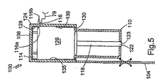
次に、図4〜図7を参照すると、締結具駆動工具の燃焼室プレートのためのラッチ機構を有した燃焼室組立体の第2の実施形態が、参照番号100により指示されている。実施形態100の特徴は、ラッチ機構が、バネにより付勢されるラッチ部材と停止部から成る単純な構成を用いている点である。図4において、燃焼室組立体100を備えた燃焼工具は、燃焼室12が取付けられている燃焼室組立体10を備えた工具と同様に、ワーク表面に接触しておらず、かつ、ハウジング106(図示せず)からワーク接触要素104が突出している。ピストンシリンダ110にスリーブ108が落下し、かつ、バネ112が該スリーブをピストンシリンダへ付勢する。分割プレート114が、好ましくはスリーブの頂部近傍において、ピストンシリンダ110とスリーブ108との間に配置されている。(図4)更に、分割プレート114は、スリーブ108に対して摺動時可能な寸法にて形成されている。側方へ往復動可能なラッチ部材116が係合すると、分割プレート114は、スリーブ108の内側の端面117に配置される。係合位置(図4〜図7)では、ラッチ部材116の端部116aがスリーブ108の内部に突出する。図5に示すように、端部116aは、好ましくは、傾斜しているが、他の形状も可能である。更に、ラッチ部材116は、好ましくは、バネ116bによって係合位置に付勢されている。
4-7, a second embodiment of a combustion chamber assembly having a latch mechanism for a combustion chamber plate of a fastener drive tool is indicated by
ピストンシリンダ110内には、ピストン24と同様に、ピストン118が往復動自在に配設されている。ピストンプレート120が、ピストンシリンダ110の頂部と概ね面一に設けられ、駆動ブレード122がピストンプレート120からピストンシリンダの底部の開口部123を通して垂下されている。
In the
次に図5を参照すると、該工具のワーク接触要素104がワーク表面に接触しており、当技術分野で周知のように、点火のために、工具は既にワークに対して押下されている。工具が押下されると、ワーク接触要素104は、スリーブ108をピストンシリンダ110から変位した最上位置まで押し上げ、こうしてスリーブ内部空間126が形成される。スリーブ108の壁128からラッチ部材116が横方向に突出した状態で、該ラッチ部材は、分割プレート114をスリーブの端壁に隣接させて該スリーブと共に上方に移動させる。同時に、スリーブシール部130を越えた部分であるスリーブ内部空間126内に空気が吸引される。スリーブ108がスリーブ最上位置(図5)に到達すると、燃料がスリーブ内部空間126に噴射され、シール部130によって内部に密封される。
Referring now to FIG. 5, the
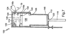
図6を参照すると、トリガー79が完全に押されて点火した後に、ラッチ部材116が解放され、つまり、横方向に外側へ移動したときの実施形態100が図示されている。第2のバネ132がスリーブ108に取着されており、スリーブ108の内壁135に配設された停止部134が分割プレートに係合するまで、分割プレート114を下方に駆動する。下方に変位した分割プレート114によって、スリーブ内部空間126内には、第1の空間136と第2の空間138とが画成される。燃料混合気は、分割プレート114の複数の穴140を通じて第2の空間138から第1の空間136へ流入する。こうして、第1の空間136には乱流が発生し、一層速い火炎速度を発生させるために用いられる。
Referring to FIG. 6, an
図7を参照すると、分割プレート114が停止部134に到達したときに、燃料混合気に点火することによって、第1の空間136に燃焼が生じる。好ましい実施形態では、当技術分野で示されるように、点火プラグによって点火が行われる。乱流状態で第1の空間136内で燃焼が開始すると、分割プレート114の穴140を通じて火炎が伝播し、第2の空間138内で点火する。燃焼ガスの急速な膨張により、ピストン118はピストンシリンダ110内を下方へ駆動され締結具に衝当する。ピストン118が、行程の終端で逆止弁146を通過すると、燃焼ガスが排気される。ピストン118は、燃焼ガスの冷却により生じる真空によって、ピストンシリンダ110内を初期位置(図4)に復帰する。
Referring to FIG. 7, when the
次に図8〜図11を参照すると、ラッチ機構を組み込んだ他の燃焼室組立体が参照番号150により指示されている。ラッチ機構100と共通の構成要素は同じ参照番号にて指示されている。実施形態150の特徴は、ラッチ機構がバネにより付勢された少なくとも1つのラッチ部材および該少なくとも1つのラッチ部材と係合するカムとを使用する点である。他の特徴は、分割プレート114の開口部を通過する空気と燃料の流れを増加して、工具の点火応答時間を最大化するようにした点である。燃焼室組立体10、100のラッチ機構は、ピストンの駆動力を最適化する分割プレート44、114の穴寸法を用いている。最適穴寸法が小さすぎて、工具のトリガーを引いた後に分割プレートが上方位置へ跳ね返ることがある。これは、工具を繰り返し点火する速度に影響する。燃焼室組立体150のラッチ機構における重要な特徴は、分割プレート152が上動動作する間は開口部が大きくなり、また、ラッチ機構により穴を閉じてピストンの駆動力を最大化するようにした点である。
With reference now to FIGS. 8-11, another combustion chamber assembly incorporating a latch mechanism is indicated by
図8を参照すると、燃焼室組立体150のラッチ機構は準備が整った位置にて図示されており、ワーク接触要素104は休止位置にあるスリーブ154に取着されている。スリーブ154は分割プレート152上に落下しており、分割プレートそれ自体はピストン118上に落下している。ハウジング156がピストンシリンダ110に取着されている。スリーブ154はピストンシリンダ110上に落下しており、バネ158が分割プレート152をピストンシリンダに対して付勢する。分割プレート152は、ピストンシリンダ110とスリーブ154との間に配設されている。第1のラッチ部材またはラッチタブ160と、鉛直方向に向けられた第2のラッチ部材またはラッチタブ162が、スリーブ154から横方向外側に突出するように、バネ163によって付勢されている。更に、タブ160、162は、スリーブ154に対して横方向に往復動自在になっている。第1のラッチタブ160はスリーブ154の頂部近傍に配置され、第2のラッチタブ162はスリーブの底部近傍に配置されている。
Referring to FIG. 8, the latch mechanism of the
図9を参照すると、ワーク接触要素104がワークに対して当接してスリーブ154を押上げ、スリーブ内部空間126が形成されている。スリーブが変位し始めると、燃料が噴射され空気と混合する。第2のラッチタブ162はトリガー79に摺動自在に係合し、分割プレート152をピストン118に対して保持する。ハウジング156にはカム168が設けられており、点火前に第1のラッチタブ160に係合してスリーブ内部空間126内に突出させる。第1と第2のラッチタブ160、162は、周方向に異なる角度位置に配置されており、凹所166(図11)が第1のラッチタブ162とは一致せず、第1のラッチタブ160に位置決めされるようになっている。
Referring to FIG. 9, the
完全に押し込まれると、トリガー79は第2のラッチタブ162を解放し、該タブは分割プレート152に対して滑り係合が解除される。第1の空間136で燃焼が開始すると、火炎は、穴168から分割プレート114を通過して凹所166のところで分割プレートを通過することが防止される。第2の空間138におけるガスの燃焼によって、ピストン118はシリンダ110を下方に駆動され締結具に衝当する。
When fully depressed, the
この構成により分割プレート152は上動する際の流体摩擦に対して一層容易に移動可能となる。この利点は、凹所166が閉塞されていないときに、分割プレート152の穴の全面積が大きくなるためである。凹所166によって、第1の空間136と第2の空間138との間で一層多い空気が輸送される。流体摩擦が低いときに、分割プレート152は、一層高い速度で第1のラッチタブ160へ向けて上方へ移動し、従って、点火サイクルが短くなる。
With this configuration, the dividing
こうして、上述した実施形態のラッチ機構は、少なくとも1つの移動プレートを燃焼動力式工具の燃焼室内に位置決めする。また、少なくとも1つのラッチ部材をバネにより付勢するようにしたラッチ機構が提供される。上述した実施形態の特徴は、少なくとも1つの移動プレートを正確に位置決めして、燃焼室内に正しい燃料混合気を達成する単純な機構が提供される点である。本発明は、また、低コストで補修が簡単な電子部品または電気部品に代わるものを提供する。 Thus, the latch mechanism of the above-described embodiment positions at least one moving plate in the combustion chamber of the combustion power tool. A latch mechanism is provided in which at least one latch member is biased by a spring. A feature of the above-described embodiments is that a simple mechanism is provided to accurately position at least one moving plate to achieve the correct fuel mixture in the combustion chamber. The present invention also provides an alternative to electronic or electrical components that are low cost and easy to repair.
締結具駆動工具の燃焼室プレートのためのラッチ機構の特の実施形態を示し、説明したが、特許請求の範囲に記載された本発明から逸脱することなく、該実施形態に変更と修正とが可能なことは当業者の当然とするところである。 While a particular embodiment of a latch mechanism for a combustion chamber plate of a fastener drive tool has been shown and described, changes and modifications may be made to the embodiment without departing from the invention as set forth in the claims. What is possible is obvious to those skilled in the art.
10 燃焼室組立体
12 燃焼室
14 円筒壁
16 環状底部
18 開口部
20 ガイドシリンダ
22 ガイドシリンダ20の底部
24 ピストン
26 ピストンプレート
28 ドライバーブレード
36 燃焼室プレート
40 円筒部分(ラッチ機構)
44 分離プレート
48 円筒ロッド(ラッチ機構)
50 肩部(ラッチ機構)
64 ラッチ部材(ラッチ機構)
66 回動点(ラッチ機構)
DESCRIPTION OF
44
50 shoulder (latch mechanism)
64 Latch member (latch mechanism)
66 Rotation point (latch mechanism)
Claims (25)
前記燃焼室を複数の空間に分割するために、前記燃焼室内での前記少なくとも1つのプレートの移動の制御部と協働する少なくとも1つのラッチ部材と、
前記ラッチ部材を解放して、前記少なくとも1つの燃焼室プレートと前記燃焼室との相対動作を許容するための手段とを具備する燃焼室組立体。 A combustion tool comprising a combustion chamber and at least one combustion chamber plate disposed in the combustion chamber, wherein the combustion chamber and the at least one combustion chamber plate are relatively reciprocated. In the combustion chamber assembly used,
At least one latch member cooperating with a controller for movement of the at least one plate within the combustion chamber to divide the combustion chamber into a plurality of spaces;
A combustion chamber assembly comprising means for releasing the latch member to allow relative movement between the at least one combustion chamber plate and the combustion chamber.
前記ラッチ部材が前記円筒状のロッドの少なくとも1つの肩部に設けられている請求項1に記載の燃焼室組立体。 The combustion chamber assembly further comprises a cylindrical rod that cooperates with the at least one plate and has a shoulder.
The combustion chamber assembly of claim 1, wherein the latch member is provided on at least one shoulder of the cylindrical rod.
前記少なくとも1つのラッチ部材が前記燃焼室スリーブ上に配設されている請求項1に記載の燃焼室組立体。 The combustion chamber assembly further comprises a combustion chamber sleeve provided displaceably from at least one combustion chamber member;
The combustion chamber assembly of claim 1, wherein the at least one latch member is disposed on the combustion chamber sleeve.
燃焼室と、
前記燃焼室の長手方向に変位可能に設けられた少なくとも1つの燃焼室プレートと、
前記少なくとも1つの燃焼室プレートが第2の燃焼室部材から変位する間、第1の燃焼室部材と共に移動できるように前記少なくとも1つの燃焼室プレートを解放可能に保持するラッチ部材と、
前記ラッチ部材を解放する手段とを具備する燃焼室組立体。 In the combustion chamber assembly of the combustion power type fastener driving tool,
A combustion chamber;
At least one combustion chamber plate provided to be displaceable in the longitudinal direction of the combustion chamber;
A latch member that releasably holds the at least one combustion chamber plate for movement with the first combustion chamber member while the at least one combustion chamber plate is displaced from the second combustion chamber member;
A combustion chamber assembly comprising means for releasing the latch member.
前記解放手段が、前記ラッチ部材に連結され前記第1の位置から前記第2の位置へ移動させるトリガーを具備する請求項11に記載の燃焼室組立体。 A latch member is provided movably in the first and second positions;
The combustion chamber assembly according to claim 11, wherein the release means includes a trigger coupled to the latch member to move from the first position to the second position.
燃焼室内で互いに相対的に移動可能に設けられた複数の燃焼室プレートと、
前記複数の燃焼室プレートの少なくとも1つと係合する第1の位置と、前記複数の燃焼室プレートの前記少なくとも1つから離間する第2の位置とを有した少なくとも1つのラッチ部材を含むラッチ手段とを具備するラッチ機構。 In a latch mechanism used in a combustion tool including first and second combustion chamber plates, wherein the combustion chamber plate is provided movably toward a fastener driving tool,
A plurality of combustion chamber plates provided to be movable relative to each other in the combustion chamber;
Latch means including at least one latch member having a first position for engaging at least one of the plurality of combustion chamber plates and a second position spaced from the at least one of the plurality of combustion chamber plates. And a latch mechanism.
燃焼室プレートと、
前記燃焼室プレートに対して移動可能に設けられたスリーブと、
前記スリーブと協働し、前記燃焼室プレートを前記スリーブに対して位置決めするラッチ部材とを具備し、
前記スリーブと前記燃焼室プレートとが工具ハウジングに対して移動可能となっている燃焼室組立体。 In a combustion chamber assembly for a fastener driving tool,
A combustion chamber plate;
A sleeve movably provided with respect to the combustion chamber plate;
A latch member cooperating with the sleeve and positioning the combustion chamber plate relative to the sleeve;
A combustion chamber assembly in which the sleeve and the combustion chamber plate are movable relative to a tool housing.
少なくとも1つの燃焼室プレートに対して移動可能に設けられたスリーブと、
前記少なくとも1つの燃焼室プレートを第1と第2の位置に保持するように形成された複数のラッチとを具備するラッチ機構。 In a latch mechanism for a fastener-driven tool having at least one combustion chamber plate,
A sleeve provided movably with respect to at least one combustion chamber plate;
A latch mechanism comprising a plurality of latches configured to hold the at least one combustion chamber plate in first and second positions.
該バネが前記燃焼室プレートを前記複数のラッチの各々に付勢するようになっている請求項21に記載のラッチ機構。 A spring that cooperates with the combustion chamber plate;
The latch mechanism of claim 21, wherein the spring biases the combustion chamber plate against each of the plurality of latches.
Applications Claiming Priority (2)
| Application Number | Priority Date | Filing Date | Title |
|---|---|---|---|
| US10/700,081 US6892524B1 (en) | 2003-11-03 | 2003-11-03 | Latching mechanism for combustion chamber plate of a fastener driving tool |
| PCT/US2004/035793 WO2005045214A1 (en) | 2003-11-03 | 2004-10-29 | Latchinig mechanism for combustion chamber plate of a fastener driving tool |
Publications (2)
| Publication Number | Publication Date |
|---|---|
| JP2007510553A true JP2007510553A (en) | 2007-04-26 |
| JP2007510553A5 JP2007510553A5 (en) | 2007-12-06 |
Family
ID=34551111
Family Applications (1)
| Application Number | Title | Priority Date | Filing Date |
|---|---|---|---|
| JP2006538240A Pending JP2007510553A (en) | 2003-11-03 | 2004-10-29 | Combustion chamber assembly and latch mechanism for fastener-driven tools |
Country Status (9)
| Country | Link |
|---|---|
| US (1) | US6892524B1 (en) |
| JP (1) | JP2007510553A (en) |
| KR (1) | KR20060115737A (en) |
| CN (1) | CN100393996C (en) |
| AU (1) | AU2004288190B2 (en) |
| CA (1) | CA2545000A1 (en) |
| NZ (1) | NZ547026A (en) |
| TW (1) | TWI253971B (en) |
| WO (1) | WO2005045214A1 (en) |
Cited By (1)
| Publication number | Priority date | Publication date | Assignee | Title |
|---|---|---|---|---|
| JP2017538594A (en) * | 2014-12-19 | 2017-12-28 | ヒルティ アクチエンゲゼルシャフト | Driving device having penetration introduction part in combustion chamber |
Families Citing this family (19)
| Publication number | Priority date | Publication date | Assignee | Title |
|---|---|---|---|---|
| US7487898B2 (en) * | 2004-02-09 | 2009-02-10 | Illinois Tool Works Inc. | Combustion chamber control for combustion-powered fastener-driving tool |
| DE102004043955B4 (en) * | 2004-09-11 | 2006-07-20 | Hilti Ag | Internal combustion setting device |
| DE102004043950B4 (en) * | 2004-09-11 | 2006-10-12 | Hilti Ag | Internal combustion setting device |
| US7383974B2 (en) * | 2005-01-03 | 2008-06-10 | Illinois Tool Works Inc. | Combustion chamber control for combustion-powered fastener-driving tool |
| FR2891760B1 (en) * | 2005-10-11 | 2008-01-11 | Maurice Liesse | INTERNAL COMBUSTION GAS HAND APPLIANCE. |
| WO2007061910A2 (en) * | 2005-11-17 | 2007-05-31 | Illinois Tool Works Inc. | Selectable firing mode with electromechanical lockout for combustion-powered fastener-driving tool |
| DE102006000179A1 (en) * | 2006-04-13 | 2007-10-18 | Hilti Ag | Internal combustion setting device |
| CA2666273C (en) * | 2006-10-16 | 2013-01-15 | Illinois Tool Works Inc. | Recharge cycle function for combustion nailer |
| JP4992404B2 (en) * | 2006-12-08 | 2012-08-08 | マックス株式会社 | Gas fired driving tool |
| DE102010063177A1 (en) * | 2010-12-15 | 2012-06-21 | Hilti Aktiengesellschaft | A bolt gun and method for operating a bolt gun |
| US9486906B2 (en) * | 2012-05-11 | 2016-11-08 | Illinois Tool Works Inc. | Lockout for fastener-driving tool |
| EP2929983A1 (en) * | 2014-04-09 | 2015-10-14 | HILTI Aktiengesellschaft | Handheld and semi-stationary setting tool |
| US10759031B2 (en) | 2014-08-28 | 2020-09-01 | Power Tech Staple and Nail, Inc. | Support for elastomeric disc valve in combustion driven fastener hand tool |
| US9862083B2 (en) | 2014-08-28 | 2018-01-09 | Power Tech Staple and Nail, Inc. | Vacuum piston retention for a combustion driven fastener hand tool |
| EP3034238A1 (en) * | 2014-12-19 | 2016-06-22 | HILTI Aktiengesellschaft | Driving device with adjustable combustion chamber |
| US11179837B2 (en) | 2017-12-01 | 2021-11-23 | Illinois Tool Works Inc. | Fastener-driving tool with multiple combustion chambers and usable with fuel canisters of varying lengths |
| US11624314B2 (en) | 2018-08-21 | 2023-04-11 | Power Tech Staple and Nail, Inc. | Combustion chamber valve and fuel system for driven fastener hand tool |
| CN109238725A (en) * | 2018-11-17 | 2019-01-18 | 邵阳学院 | A kind of the constant volume combustion bomb device and its control system of analog turbulent motion |
| US20220042497A1 (en) * | 2020-08-04 | 2022-02-10 | Navita Energy, Inc. | Enhanced low temperature difference-powered devices, systems, and methods |
Family Cites Families (21)
| Publication number | Priority date | Publication date | Assignee | Title |
|---|---|---|---|---|
| US3967771A (en) * | 1974-12-16 | 1976-07-06 | Smith James E | Self-contained impact tool |
| FR2463267A1 (en) * | 1979-08-08 | 1981-02-20 | Liesse Maurice | THERMAL GENERATOR OF PULSES |
| US4773581A (en) | 1986-06-13 | 1988-09-27 | Hitachi Koki Company, Ltd. | Combustion gas powered tool |
| US4717060A (en) | 1986-07-02 | 1988-01-05 | Senco Products, Inc. | Self-contained internal combustion fastener driving tool |
| US4712379A (en) | 1987-01-08 | 1987-12-15 | Pow-R Tools Corporation | Manual recycler for detonating impact tool |
| DE4032204C2 (en) * | 1990-10-11 | 1999-10-21 | Hilti Ag | Setting tool for fasteners |
| DE4032202C2 (en) | 1990-10-11 | 1999-10-21 | Hilti Ag | Setting tool for fasteners |
| US5680980A (en) | 1995-11-27 | 1997-10-28 | Illinois Tool Works Inc. | Fuel injection system for combustion-powered tool |
| US6145724A (en) * | 1997-10-31 | 2000-11-14 | Illinois Tool Works, Inc. | Combustion powered tool with combustion chamber delay |
| US6260519B1 (en) | 1997-12-31 | 2001-07-17 | Porter-Cable Corporation | Internal combustion fastener driving tool accelerator plate |
| DE19950350C2 (en) | 1999-10-19 | 2002-06-20 | Hilti Ag | Dosing head, in particular for setting tools operated by internal combustion engines |
| DE19950345C2 (en) | 1999-10-19 | 2003-06-05 | Hilti Ag | Method and device for driving a piston of an internal combustion-powered working device, in particular a setting device for fastening elements |
| DE19950352C2 (en) | 1999-10-19 | 2002-03-07 | Hilti Ag | Portable, combustion powered tool and method for driving its piston |
| DE19962597C2 (en) | 1999-12-23 | 2002-07-04 | Hilti Ag | Portable, combustion powered tool and method for providing a gas mixture in its combustion chamber |
| DE19962598C2 (en) | 1999-12-23 | 2002-03-14 | Hilti Ag | Portable, combustion-powered working device, in particular setting device for fastening elements and method for its operational control |
| DE19962711C2 (en) | 1999-12-23 | 2002-06-27 | Hilti Ag | Portable, combustion powered tool with changeable prechamber |
| DE19962599C2 (en) | 1999-12-23 | 2002-09-19 | Hilti Ag | Portable, combustion-powered working tool, in particular setting tool for fastening elements, and method for its operational control |
| DE19962696C1 (en) | 1999-12-23 | 2001-06-07 | Hilti Ag | Power tool with an internal combustion power unit to drive mountings home has a brake system at the piston rod with an adjustable braking force to set the power transferred from the combustion chamber to the piston |
| DE19962695B4 (en) | 1999-12-23 | 2006-02-16 | Hilti Ag | Portable, combustion-powered work tool with variable main chamber |
| FR2832344B1 (en) | 2001-11-21 | 2004-01-23 | Spit Soc Prospect Inv Techn | COMPRESSED GAS PISTON FIXING APPARATUS |
| US6592014B2 (en) * | 2001-12-13 | 2003-07-15 | Illinois Tool Works Inc. | Lockout mechanism for fastener driving tool |
-
2003
- 2003-11-03 US US10/700,081 patent/US6892524B1/en not_active Expired - Fee Related
-
2004
- 2004-10-29 CN CNB2004800328824A patent/CN100393996C/en not_active Expired - Fee Related
- 2004-10-29 CA CA002545000A patent/CA2545000A1/en not_active Abandoned
- 2004-10-29 WO PCT/US2004/035793 patent/WO2005045214A1/en active Application Filing
- 2004-10-29 KR KR1020067008601A patent/KR20060115737A/en not_active Application Discontinuation
- 2004-10-29 AU AU2004288190A patent/AU2004288190B2/en not_active Ceased
- 2004-10-29 NZ NZ547026A patent/NZ547026A/en not_active IP Right Cessation
- 2004-10-29 JP JP2006538240A patent/JP2007510553A/en active Pending
- 2004-11-03 TW TW093133540A patent/TWI253971B/en not_active IP Right Cessation
Cited By (1)
| Publication number | Priority date | Publication date | Assignee | Title |
|---|---|---|---|---|
| JP2017538594A (en) * | 2014-12-19 | 2017-12-28 | ヒルティ アクチエンゲゼルシャフト | Driving device having penetration introduction part in combustion chamber |
Also Published As
| Publication number | Publication date |
|---|---|
| NZ547026A (en) | 2009-09-25 |
| TWI253971B (en) | 2006-05-01 |
| WO2005045214A1 (en) | 2005-05-19 |
| KR20060115737A (en) | 2006-11-09 |
| US20050091962A1 (en) | 2005-05-05 |
| CA2545000A1 (en) | 2005-05-19 |
| TW200518889A (en) | 2005-06-16 |
| US6892524B1 (en) | 2005-05-17 |
| CN1878935A (en) | 2006-12-13 |
| CN100393996C (en) | 2008-06-11 |
| AU2004288190B2 (en) | 2008-05-01 |
| AU2004288190A1 (en) | 2005-05-19 |
Similar Documents
| Publication | Publication Date | Title |
|---|---|---|
| JP2007510553A (en) | Combustion chamber assembly and latch mechanism for fastener-driven tools | |
| JP4833864B2 (en) | Exhaust system for combustion powered fastener drive tools | |
| JP4741518B2 (en) | Combustion chamber control for combustion powered fastener drive tools | |
| EP1813394B1 (en) | Combustion chamber control for combustion-powered fastener-driving tool | |
| EP2061631B1 (en) | Combustion-type power tool | |
| WO2006123693A1 (en) | Fuel gas type hammering tool | |
| WO2007018179A1 (en) | Gas combustion type driving tool | |
| JP2007237328A (en) | Combustion type power tool | |
| US7210431B2 (en) | Combustion-type power tool with exhaust gas flow regulating rib | |
| US6755335B2 (en) | Gas-operated setting tool | |
| US6695195B2 (en) | Combustion-powered nail gun | |
| AU2004287842B2 (en) | Combustion apparatus having collapsible volume | |
| JP2005153105A (en) | Combustion type power tool | |
| JP5067046B2 (en) | Gas fired driving tool | |
| JP2019126848A (en) | Placing tool | |
| JP4075353B2 (en) | Gas nailer | |
| JP2006000946A (en) | Combustion type working tool | |
| JP2005040875A (en) | Combustion power tool | |
| JPS62297076A (en) | Gas combustion type piston drive | |
| JPS63147012A (en) | Scavenger for internal combustion-type piston driver | |
| JP2019188538A (en) | Driving tool |
Legal Events
| Date | Code | Title | Description |
|---|---|---|---|
| A521 | Request for written amendment filed |
Free format text: JAPANESE INTERMEDIATE CODE: A523 Effective date: 20071015 |
|
| A621 | Written request for application examination |
Free format text: JAPANESE INTERMEDIATE CODE: A621 Effective date: 20071015 |
|
| A131 | Notification of reasons for refusal |
Free format text: JAPANESE INTERMEDIATE CODE: A131 Effective date: 20090421 |
|
| A02 | Decision of refusal |
Free format text: JAPANESE INTERMEDIATE CODE: A02 Effective date: 20090929 |