JP2007507290A - Method and associated apparatus for generating retrograde perfusion - Google Patents
Method and associated apparatus for generating retrograde perfusion Download PDFInfo
- Publication number
- JP2007507290A JP2007507290A JP2006533878A JP2006533878A JP2007507290A JP 2007507290 A JP2007507290 A JP 2007507290A JP 2006533878 A JP2006533878 A JP 2006533878A JP 2006533878 A JP2006533878 A JP 2006533878A JP 2007507290 A JP2007507290 A JP 2007507290A
- Authority
- JP
- Japan
- Prior art keywords
- coronary vein
- blood flow
- graft
- coronary
- passage
- Prior art date
- Legal status (The legal status is an assumption and is not a legal conclusion. Google has not performed a legal analysis and makes no representation as to the accuracy of the status listed.)
- Withdrawn
Links
Images


Classifications
-
- A—HUMAN NECESSITIES
- A61—MEDICAL OR VETERINARY SCIENCE; HYGIENE
- A61F—FILTERS IMPLANTABLE INTO BLOOD VESSELS; PROSTHESES; DEVICES PROVIDING PATENCY TO, OR PREVENTING COLLAPSING OF, TUBULAR STRUCTURES OF THE BODY, e.g. STENTS; ORTHOPAEDIC, NURSING OR CONTRACEPTIVE DEVICES; FOMENTATION; TREATMENT OR PROTECTION OF EYES OR EARS; BANDAGES, DRESSINGS OR ABSORBENT PADS; FIRST-AID KITS
- A61F2/00—Filters implantable into blood vessels; Prostheses, i.e. artificial substitutes or replacements for parts of the body; Appliances for connecting them with the body; Devices providing patency to, or preventing collapsing of, tubular structures of the body, e.g. stents
- A61F2/02—Prostheses implantable into the body
- A61F2/24—Heart valves ; Vascular valves, e.g. venous valves; Heart implants, e.g. passive devices for improving the function of the native valve or the heart muscle; Transmyocardial revascularisation [TMR] devices; Valves implantable in the body
- A61F2/2493—Transmyocardial revascularisation [TMR] devices
-
- A—HUMAN NECESSITIES
- A61—MEDICAL OR VETERINARY SCIENCE; HYGIENE
- A61F—FILTERS IMPLANTABLE INTO BLOOD VESSELS; PROSTHESES; DEVICES PROVIDING PATENCY TO, OR PREVENTING COLLAPSING OF, TUBULAR STRUCTURES OF THE BODY, e.g. STENTS; ORTHOPAEDIC, NURSING OR CONTRACEPTIVE DEVICES; FOMENTATION; TREATMENT OR PROTECTION OF EYES OR EARS; BANDAGES, DRESSINGS OR ABSORBENT PADS; FIRST-AID KITS
- A61F2/00—Filters implantable into blood vessels; Prostheses, i.e. artificial substitutes or replacements for parts of the body; Appliances for connecting them with the body; Devices providing patency to, or preventing collapsing of, tubular structures of the body, e.g. stents
- A61F2/01—Filters implantable into blood vessels
- A61F2/0105—Open ended, i.e. legs gathered only at one side
-
- A—HUMAN NECESSITIES
- A61—MEDICAL OR VETERINARY SCIENCE; HYGIENE
- A61F—FILTERS IMPLANTABLE INTO BLOOD VESSELS; PROSTHESES; DEVICES PROVIDING PATENCY TO, OR PREVENTING COLLAPSING OF, TUBULAR STRUCTURES OF THE BODY, e.g. STENTS; ORTHOPAEDIC, NURSING OR CONTRACEPTIVE DEVICES; FOMENTATION; TREATMENT OR PROTECTION OF EYES OR EARS; BANDAGES, DRESSINGS OR ABSORBENT PADS; FIRST-AID KITS
- A61F2/00—Filters implantable into blood vessels; Prostheses, i.e. artificial substitutes or replacements for parts of the body; Appliances for connecting them with the body; Devices providing patency to, or preventing collapsing of, tubular structures of the body, e.g. stents
- A61F2/82—Devices providing patency to, or preventing collapsing of, tubular structures of the body, e.g. stents
- A61F2/86—Stents in a form characterised by the wire-like elements; Stents in the form characterised by a net-like or mesh-like structure
- A61F2/90—Stents in a form characterised by the wire-like elements; Stents in the form characterised by a net-like or mesh-like structure characterised by a net-like or mesh-like structure
- A61F2/91—Stents in a form characterised by the wire-like elements; Stents in the form characterised by a net-like or mesh-like structure characterised by a net-like or mesh-like structure made from perforated sheet material or tubes, e.g. perforated by laser cuts or etched holes
- A61F2/915—Stents in a form characterised by the wire-like elements; Stents in the form characterised by a net-like or mesh-like structure characterised by a net-like or mesh-like structure made from perforated sheet material or tubes, e.g. perforated by laser cuts or etched holes with bands having a meander structure, adjacent bands being connected to each other
-
- A—HUMAN NECESSITIES
- A61—MEDICAL OR VETERINARY SCIENCE; HYGIENE
- A61M—DEVICES FOR INTRODUCING MEDIA INTO, OR ONTO, THE BODY; DEVICES FOR TRANSDUCING BODY MEDIA OR FOR TAKING MEDIA FROM THE BODY; DEVICES FOR PRODUCING OR ENDING SLEEP OR STUPOR
- A61M27/00—Drainage appliance for wounds or the like, i.e. wound drains, implanted drains
- A61M27/002—Implant devices for drainage of body fluids from one part of the body to another
-
- A—HUMAN NECESSITIES
- A61—MEDICAL OR VETERINARY SCIENCE; HYGIENE
- A61F—FILTERS IMPLANTABLE INTO BLOOD VESSELS; PROSTHESES; DEVICES PROVIDING PATENCY TO, OR PREVENTING COLLAPSING OF, TUBULAR STRUCTURES OF THE BODY, e.g. STENTS; ORTHOPAEDIC, NURSING OR CONTRACEPTIVE DEVICES; FOMENTATION; TREATMENT OR PROTECTION OF EYES OR EARS; BANDAGES, DRESSINGS OR ABSORBENT PADS; FIRST-AID KITS
- A61F2/00—Filters implantable into blood vessels; Prostheses, i.e. artificial substitutes or replacements for parts of the body; Appliances for connecting them with the body; Devices providing patency to, or preventing collapsing of, tubular structures of the body, e.g. stents
- A61F2/01—Filters implantable into blood vessels
- A61F2002/018—Filters implantable into blood vessels made from tubes or sheets of material, e.g. by etching or laser-cutting
-
- A—HUMAN NECESSITIES
- A61—MEDICAL OR VETERINARY SCIENCE; HYGIENE
- A61F—FILTERS IMPLANTABLE INTO BLOOD VESSELS; PROSTHESES; DEVICES PROVIDING PATENCY TO, OR PREVENTING COLLAPSING OF, TUBULAR STRUCTURES OF THE BODY, e.g. STENTS; ORTHOPAEDIC, NURSING OR CONTRACEPTIVE DEVICES; FOMENTATION; TREATMENT OR PROTECTION OF EYES OR EARS; BANDAGES, DRESSINGS OR ABSORBENT PADS; FIRST-AID KITS
- A61F2/00—Filters implantable into blood vessels; Prostheses, i.e. artificial substitutes or replacements for parts of the body; Appliances for connecting them with the body; Devices providing patency to, or preventing collapsing of, tubular structures of the body, e.g. stents
- A61F2/02—Prostheses implantable into the body
- A61F2/04—Hollow or tubular parts of organs, e.g. bladders, tracheae, bronchi or bile ducts
- A61F2/06—Blood vessels
- A61F2002/068—Modifying the blood flow model, e.g. by diffuser or deflector
-
- A—HUMAN NECESSITIES
- A61—MEDICAL OR VETERINARY SCIENCE; HYGIENE
- A61F—FILTERS IMPLANTABLE INTO BLOOD VESSELS; PROSTHESES; DEVICES PROVIDING PATENCY TO, OR PREVENTING COLLAPSING OF, TUBULAR STRUCTURES OF THE BODY, e.g. STENTS; ORTHOPAEDIC, NURSING OR CONTRACEPTIVE DEVICES; FOMENTATION; TREATMENT OR PROTECTION OF EYES OR EARS; BANDAGES, DRESSINGS OR ABSORBENT PADS; FIRST-AID KITS
- A61F2/00—Filters implantable into blood vessels; Prostheses, i.e. artificial substitutes or replacements for parts of the body; Appliances for connecting them with the body; Devices providing patency to, or preventing collapsing of, tubular structures of the body, e.g. stents
- A61F2/82—Devices providing patency to, or preventing collapsing of, tubular structures of the body, e.g. stents
- A61F2/86—Stents in a form characterised by the wire-like elements; Stents in the form characterised by a net-like or mesh-like structure
- A61F2/90—Stents in a form characterised by the wire-like elements; Stents in the form characterised by a net-like or mesh-like structure characterised by a net-like or mesh-like structure
- A61F2/91—Stents in a form characterised by the wire-like elements; Stents in the form characterised by a net-like or mesh-like structure characterised by a net-like or mesh-like structure made from perforated sheet material or tubes, e.g. perforated by laser cuts or etched holes
- A61F2/915—Stents in a form characterised by the wire-like elements; Stents in the form characterised by a net-like or mesh-like structure characterised by a net-like or mesh-like structure made from perforated sheet material or tubes, e.g. perforated by laser cuts or etched holes with bands having a meander structure, adjacent bands being connected to each other
- A61F2002/91533—Stents in a form characterised by the wire-like elements; Stents in the form characterised by a net-like or mesh-like structure characterised by a net-like or mesh-like structure made from perforated sheet material or tubes, e.g. perforated by laser cuts or etched holes with bands having a meander structure, adjacent bands being connected to each other characterised by the phase between adjacent bands
-
- A—HUMAN NECESSITIES
- A61—MEDICAL OR VETERINARY SCIENCE; HYGIENE
- A61F—FILTERS IMPLANTABLE INTO BLOOD VESSELS; PROSTHESES; DEVICES PROVIDING PATENCY TO, OR PREVENTING COLLAPSING OF, TUBULAR STRUCTURES OF THE BODY, e.g. STENTS; ORTHOPAEDIC, NURSING OR CONTRACEPTIVE DEVICES; FOMENTATION; TREATMENT OR PROTECTION OF EYES OR EARS; BANDAGES, DRESSINGS OR ABSORBENT PADS; FIRST-AID KITS
- A61F2/00—Filters implantable into blood vessels; Prostheses, i.e. artificial substitutes or replacements for parts of the body; Appliances for connecting them with the body; Devices providing patency to, or preventing collapsing of, tubular structures of the body, e.g. stents
- A61F2/82—Devices providing patency to, or preventing collapsing of, tubular structures of the body, e.g. stents
- A61F2/86—Stents in a form characterised by the wire-like elements; Stents in the form characterised by a net-like or mesh-like structure
- A61F2/90—Stents in a form characterised by the wire-like elements; Stents in the form characterised by a net-like or mesh-like structure characterised by a net-like or mesh-like structure
- A61F2/91—Stents in a form characterised by the wire-like elements; Stents in the form characterised by a net-like or mesh-like structure characterised by a net-like or mesh-like structure made from perforated sheet material or tubes, e.g. perforated by laser cuts or etched holes
- A61F2/915—Stents in a form characterised by the wire-like elements; Stents in the form characterised by a net-like or mesh-like structure characterised by a net-like or mesh-like structure made from perforated sheet material or tubes, e.g. perforated by laser cuts or etched holes with bands having a meander structure, adjacent bands being connected to each other
- A61F2002/9155—Adjacent bands being connected to each other
- A61F2002/91575—Adjacent bands being connected to each other connected peak to trough
-
- A—HUMAN NECESSITIES
- A61—MEDICAL OR VETERINARY SCIENCE; HYGIENE
- A61F—FILTERS IMPLANTABLE INTO BLOOD VESSELS; PROSTHESES; DEVICES PROVIDING PATENCY TO, OR PREVENTING COLLAPSING OF, TUBULAR STRUCTURES OF THE BODY, e.g. STENTS; ORTHOPAEDIC, NURSING OR CONTRACEPTIVE DEVICES; FOMENTATION; TREATMENT OR PROTECTION OF EYES OR EARS; BANDAGES, DRESSINGS OR ABSORBENT PADS; FIRST-AID KITS
- A61F2220/00—Fixations or connections for prostheses classified in groups A61F2/00 - A61F2/26 or A61F2/82 or A61F9/00 or A61F11/00 or subgroups thereof
- A61F2220/0008—Fixation appliances for connecting prostheses to the body
- A61F2220/0016—Fixation appliances for connecting prostheses to the body with sharp anchoring protrusions, e.g. barbs, pins, spikes
-
- A—HUMAN NECESSITIES
- A61—MEDICAL OR VETERINARY SCIENCE; HYGIENE
- A61F—FILTERS IMPLANTABLE INTO BLOOD VESSELS; PROSTHESES; DEVICES PROVIDING PATENCY TO, OR PREVENTING COLLAPSING OF, TUBULAR STRUCTURES OF THE BODY, e.g. STENTS; ORTHOPAEDIC, NURSING OR CONTRACEPTIVE DEVICES; FOMENTATION; TREATMENT OR PROTECTION OF EYES OR EARS; BANDAGES, DRESSINGS OR ABSORBENT PADS; FIRST-AID KITS
- A61F2230/00—Geometry of prostheses classified in groups A61F2/00 - A61F2/26 or A61F2/82 or A61F9/00 or A61F11/00 or subgroups thereof
- A61F2230/0002—Two-dimensional shapes, e.g. cross-sections
- A61F2230/0004—Rounded shapes, e.g. with rounded corners
- A61F2230/0006—Rounded shapes, e.g. with rounded corners circular
-
- A—HUMAN NECESSITIES
- A61—MEDICAL OR VETERINARY SCIENCE; HYGIENE
- A61F—FILTERS IMPLANTABLE INTO BLOOD VESSELS; PROSTHESES; DEVICES PROVIDING PATENCY TO, OR PREVENTING COLLAPSING OF, TUBULAR STRUCTURES OF THE BODY, e.g. STENTS; ORTHOPAEDIC, NURSING OR CONTRACEPTIVE DEVICES; FOMENTATION; TREATMENT OR PROTECTION OF EYES OR EARS; BANDAGES, DRESSINGS OR ABSORBENT PADS; FIRST-AID KITS
- A61F2230/00—Geometry of prostheses classified in groups A61F2/00 - A61F2/26 or A61F2/82 or A61F9/00 or A61F11/00 or subgroups thereof
- A61F2230/0063—Three-dimensional shapes
- A61F2230/0067—Three-dimensional shapes conical
-
- A—HUMAN NECESSITIES
- A61—MEDICAL OR VETERINARY SCIENCE; HYGIENE
- A61F—FILTERS IMPLANTABLE INTO BLOOD VESSELS; PROSTHESES; DEVICES PROVIDING PATENCY TO, OR PREVENTING COLLAPSING OF, TUBULAR STRUCTURES OF THE BODY, e.g. STENTS; ORTHOPAEDIC, NURSING OR CONTRACEPTIVE DEVICES; FOMENTATION; TREATMENT OR PROTECTION OF EYES OR EARS; BANDAGES, DRESSINGS OR ABSORBENT PADS; FIRST-AID KITS
- A61F2230/00—Geometry of prostheses classified in groups A61F2/00 - A61F2/26 or A61F2/82 or A61F9/00 or A61F11/00 or subgroups thereof
- A61F2230/0063—Three-dimensional shapes
- A61F2230/0069—Three-dimensional shapes cylindrical
-
- A—HUMAN NECESSITIES
- A61—MEDICAL OR VETERINARY SCIENCE; HYGIENE
- A61F—FILTERS IMPLANTABLE INTO BLOOD VESSELS; PROSTHESES; DEVICES PROVIDING PATENCY TO, OR PREVENTING COLLAPSING OF, TUBULAR STRUCTURES OF THE BODY, e.g. STENTS; ORTHOPAEDIC, NURSING OR CONTRACEPTIVE DEVICES; FOMENTATION; TREATMENT OR PROTECTION OF EYES OR EARS; BANDAGES, DRESSINGS OR ABSORBENT PADS; FIRST-AID KITS
- A61F2230/00—Geometry of prostheses classified in groups A61F2/00 - A61F2/26 or A61F2/82 or A61F9/00 or A61F11/00 or subgroups thereof
- A61F2230/0063—Three-dimensional shapes
- A61F2230/0073—Quadric-shaped
- A61F2230/0078—Quadric-shaped hyperboloidal
-
- A—HUMAN NECESSITIES
- A61—MEDICAL OR VETERINARY SCIENCE; HYGIENE
- A61F—FILTERS IMPLANTABLE INTO BLOOD VESSELS; PROSTHESES; DEVICES PROVIDING PATENCY TO, OR PREVENTING COLLAPSING OF, TUBULAR STRUCTURES OF THE BODY, e.g. STENTS; ORTHOPAEDIC, NURSING OR CONTRACEPTIVE DEVICES; FOMENTATION; TREATMENT OR PROTECTION OF EYES OR EARS; BANDAGES, DRESSINGS OR ABSORBENT PADS; FIRST-AID KITS
- A61F2230/00—Geometry of prostheses classified in groups A61F2/00 - A61F2/26 or A61F2/82 or A61F9/00 or A61F11/00 or subgroups thereof
- A61F2230/0063—Three-dimensional shapes
- A61F2230/0073—Quadric-shaped
- A61F2230/008—Quadric-shaped paraboloidal
-
- A—HUMAN NECESSITIES
- A61—MEDICAL OR VETERINARY SCIENCE; HYGIENE
- A61F—FILTERS IMPLANTABLE INTO BLOOD VESSELS; PROSTHESES; DEVICES PROVIDING PATENCY TO, OR PREVENTING COLLAPSING OF, TUBULAR STRUCTURES OF THE BODY, e.g. STENTS; ORTHOPAEDIC, NURSING OR CONTRACEPTIVE DEVICES; FOMENTATION; TREATMENT OR PROTECTION OF EYES OR EARS; BANDAGES, DRESSINGS OR ABSORBENT PADS; FIRST-AID KITS
- A61F2250/00—Special features of prostheses classified in groups A61F2/00 - A61F2/26 or A61F2/82 or A61F9/00 or A61F11/00 or subgroups thereof
- A61F2250/0014—Special features of prostheses classified in groups A61F2/00 - A61F2/26 or A61F2/82 or A61F9/00 or A61F11/00 or subgroups thereof having different values of a given property or geometrical feature, e.g. mechanical property or material property, at different locations within the same prosthesis
- A61F2250/0039—Special features of prostheses classified in groups A61F2/00 - A61F2/26 or A61F2/82 or A61F9/00 or A61F11/00 or subgroups thereof having different values of a given property or geometrical feature, e.g. mechanical property or material property, at different locations within the same prosthesis differing in diameter
Abstract
冠状静脈内に逆行性の血液流れを生成することにより心臓を治療する方法および関連装置が、血液を含む解剖学的構造と冠状静脈との間の通路を通して血液を流すことにより、冠状静脈内で逆行性の血液流を生成することを含む。この方法および関連装置はさらに、測定内部圧力を決定するために冠状静脈の内部圧力を測定すること、および測定内部圧力に基づいて逆行性の血液流の方向に対して前記通路の上流側位置で冠状静脈を少なくとも部分的に閉鎖することを含む。 A method and related apparatus for treating the heart by generating retrograde blood flow in the coronary vein is provided in the coronary vein by flowing blood through a passage between the anatomical structure containing the blood and the coronary vein. Generating a retrograde blood flow. The method and related apparatus further measure the internal pressure of the coronary vein to determine the measured internal pressure, and at a location upstream of the passage relative to the direction of retrograde blood flow based on the measured internal pressure. Including at least partially closing the coronary vein.
Description
本出願は、2003年9月29日出願の米国特許出願番号第10/671,581号に対する優先権を主張するものである。 This application claims priority to US patent application Ser. No. 10 / 671,581 filed Sep. 29, 2003.
本発明は静脈系に逆行性の流体流れを生成する方法および関連装置に関する。例えば前記方法および関連装置は、例えば、左心室または冠状動脈などの酸素を豊富に含んだ血液を含む血液を含有する解剖学的構造体と、冠状動脈との間に通路を形成することにより、および通路の上流の位置で冠状静脈を少なくとも部分的に閉鎖することによって逆行性潅流が生成する間に、冠状静脈の内部圧力を制御することにより、冠状静脈内に酸素を豊富に含んだ血流の逆行性流れを生成する。 The present invention relates to a method and associated apparatus for generating retrograde fluid flow in the venous system. For example, the method and related apparatus can form a passage between a coronary artery and an anatomical structure containing blood containing oxygen-rich blood, such as the left ventricle or coronary artery, for example. And oxygen-rich blood flow in the coronary vein by controlling the internal pressure of the coronary vein while retrograde perfusion is generated by at least partially closing the coronary vein at a location upstream of the passageway Generate a retrograde flow of
心不全の一般的な形態は、例えば冠状動脈など、様々な血管構造体の壁への血小板の堆積を含む。壁上に堆積した血小板は、動脈に部分的または全体的な閉塞を発生する可能性がある。このような閉塞は、通常左心室から大動脈弁を通って動脈に入る、動脈を通る血流を制限または完全に遮断する恐れがある。冠状動脈は心臓壁を形成する筋肉内の様々な血管に血液を供給するため、例えば虚血などの、冠状動脈を通る血流の制限または遮断は心筋に損傷を与える結果になる。虚血組織は心臓のポンピング能力を低減させ、結果として心臓機能を低下させる。場合によっては、心臓能力が低下する結果として心臓発作を起こす可能性がある。 A common form of heart failure involves the deposition of platelets on the walls of various vascular structures, such as coronary arteries. Platelets deposited on the wall can cause partial or total occlusion of the artery. Such an occlusion can limit or completely block blood flow through the artery, which normally enters the artery from the left ventricle through the aortic valve. Because the coronary arteries supply blood to various blood vessels in the muscle that form the heart wall, restricting or blocking blood flow through the coronary arteries, such as ischemia, can result in damage to the myocardium. Ischemic tissue reduces the heart's ability to pump and consequently reduces cardiac function. In some cases, a heart attack can occur as a result of reduced cardiac performance.
この種の心臓の症状を治療するために様々な技術が開発されている。例えば、冠状動脈バイパス移植術(CABG)と称される外科技術では、患者から(通常大腿静脈から)静脈またはその一部を除去し、その静脈を移植して、閉塞部の上流および下流で冠状動脈の一部と接続することを含む。この結果、血流が閉塞部の周囲を迂回して静脈移植片を通して送られることにより、酸素を豊富に含んだ血液を心臓壁の血管に送ることができる。CABGは一般に回復時間が比較的長くなる観血療法として実行される。さらに、多くの場合、患者はCABGにおいてなされる静脈の除去の結果として大きな不快感を経験する。さらに、冠状動脈に移植された静脈は耐用年数が限られている。 Various techniques have been developed to treat this type of heart condition. For example, in a surgical technique called coronary artery bypass grafting (CABG), a vein or part thereof is removed from a patient (usually from the femoral vein) and the vein is implanted to coronate upstream and downstream of the occlusion. Including connecting to a portion of the artery. As a result, the blood flow is diverted around the obstruction and sent through the vein graft, so that oxygen-rich blood can be sent to the blood vessels in the heart wall. CABG is generally performed as an open therapy with a relatively long recovery time. Moreover, in many cases, patients experience great discomfort as a result of vein removal done in CABG. In addition, veins implanted in coronary arteries have a limited useful life.
冠動脈血管形成術は、バイパス術の代替として実行できる、閉塞部を有する他の形態の動脈の治療を表す。この技法では、バルーンカテーテルが冠状動脈に経皮的に挿入される。カテーテルが挿入されてバルーンが治療される閉塞に隣接する位置に達すると、バルーンが膨張して閉塞位置において動脈を拡大する。多くの場合、この技法ではバルーンの膨張および収縮を繰り返し、動脈の望ましい拡大を達成する。この技法は、閉塞位置で動脈と同一線上にステントを配置し、動脈の適正な拡大を維持することを含む。ステントの送達は、拡大バルーンカテーテルを除去後、バルーンカテーテルを挿入して動脈にステントを送り込むことにより達成される。複数のバルーンステントの送達カテーテルは、動脈を拡大して、カテーテルの一回の挿入で患者体内にステントを配置することができる。 Coronary angioplasty represents the treatment of other forms of arteries with obstructions that can be performed as an alternative to bypass surgery. In this technique, a balloon catheter is inserted percutaneously into the coronary artery. When the catheter is inserted and reaches a position adjacent to the occlusion where the balloon is treated, the balloon is inflated to expand the artery in the occluded position. In many cases, this technique repeats balloon inflation and deflation to achieve the desired expansion of the artery. This technique involves placing the stent collinear with the artery at the occluded position to maintain proper expansion of the artery. Stent delivery is accomplished by removing the dilatation balloon catheter and then inserting the balloon catheter to deliver the stent into the artery. Multiple balloon stent delivery catheters can expand the artery and place the stent within the patient with a single insertion of the catheter.
さらに、別の技法は、冠状動脈内の閉塞部の上流位置において冠状動脈と冠状静脈との間に通路を形成することにより、酸素を豊富に含む血液を心臓壁に逆行して送ることを含む。この技法では一般に、冠状静脈を縛るかまたは別の方法で閉鎖して、通路から冠状静脈洞への順行性の血流を停止させる。したがって、動脈血は、冠状動脈から、通路を通して冠状静脈に導かれ、そこで逆行して流れて、心臓壁を潅流する。しかし、この逆行性潅流技法(すなわち、動脈系から静脈系に逆行する流れを利用して心臓を潅流する)は、出血性梗塞の発生率または細胞死をもたらす組織の充血の発生率が比較的高いことと関連している。このような問題は、冠状静脈洞への順行性の血流の遮断により少なくとも一部で発生する。言い換えると、一定の条件下で、静脈系を通る心臓からの流出を認めることなく逆行性潅流を行うことは心臓の過剰潅流を引き起こす可能性がある。 Yet another technique involves sending oxygen-rich blood back to the heart wall by creating a passage between the coronary artery and the coronary vein at a location upstream of the occlusion within the coronary artery. . This technique generally ties up or otherwise closes the coronary vein to stop antegrade blood flow from the passageway to the coronary sinus. Thus, arterial blood is directed from the coronary artery through the passageway to the coronary vein where it flows backwards and perfuses the heart wall. However, this retrograde perfusion technique (ie, perfusing the heart using a retrograde flow from the arterial system to the venous system) has a relatively high incidence of hemorrhagic infarction or tissue hyperemia leading to cell death. Related to being expensive. Such problems occur at least in part due to antegrade blockage of blood to the coronary sinus. In other words, under certain conditions, performing retrograde perfusion without any outflow from the heart through the venous system can cause overperfusion of the heart.
さらに、冠状動脈から冠状静脈に血液を逆行して送出することにより心臓を逆行潅流する従来の技法は、冠状静脈が受ける内部圧力を考慮していない。この内部圧力は、上で説明したとおり、静脈自体ならびに心臓を潅流する能力両方に影響を与える。心臓の過剰潅流を生じることに加えて、例えば、通路の位置に近接する冠状静脈を完全に閉鎖または縛ることは、正常状態(すなわち、動脈の逆行性血流が存在しない)で見られる圧力以上に静脈の圧力が増加するため、静脈に損傷を与えることがある。 Further, conventional techniques for retroperfusion of the heart by retrogressing blood from the coronary artery to the coronary vein do not take into account the internal pressure experienced by the coronary vein. This internal pressure, as explained above, affects both the vein itself as well as the ability to perfuse the heart. In addition to causing hyperperfusion of the heart, for example, completely closing or tying a coronary vein close to the location of the passage is above the pressure seen in normal conditions (ie, the absence of retrograde arterial blood flow) Because of increased vein pressure, the veins may be damaged.
しかし、他方では、静脈を閉鎖されない状態のままにしておくと、静脈を通る逆行性血流と静脈を通る順行性血流の間で対抗するため心臓の非効率な潅流を生じる。このような対抗する流れは心臓の潅流不足を招く。 On the other hand, however, leaving the vein unoccupied results in inefficient perfusion of the heart to counteract between retrograde blood flow through the vein and antegrade blood flow through the vein. Such opposing flow leads to insufficient perfusion of the heart.
したがって、静脈系を通る少なくとも若干の順行性血流を認める、心臓を逆行潅流する技法を提供することが望ましい。 Accordingly, it would be desirable to provide a technique for retroperfusion of the heart that allows at least some antegrade blood flow through the venous system.
さらに、例えば、逆行性血流が発生する血管内で生じる圧力を制限することにより、血管内の圧力を制御する、逆行性潅流の技法を提供することが望ましい。例えば、圧力を制限して、圧力が、冠状静脈の測定された内部圧力に基づいて選択される、ほぼ所定の値またはその値未満または所定の範囲の値に維持されることが望ましい。 Furthermore, it would be desirable to provide a retrograde perfusion technique that controls the pressure in a blood vessel, for example, by limiting the pressure that occurs in the blood vessel where retrograde blood flow occurs. For example, it may be desirable to limit the pressure and maintain the pressure at approximately a predetermined value, less than or within a predetermined range selected based on the measured internal pressure of the coronary vein.
本発明は、上述の1つまたは複数の態様、目的または利点を実行することなく実現できることは理解されるべきである。他の態様は下記の詳細な説明から明らかになるであろう。 It is to be understood that the present invention can be realized without carrying out one or more of the aspects, objects or advantages described above. Other aspects will become apparent from the detailed description below.
本発明の態様は心臓の治療方法を含み、この方法は、血液を含む解剖学的構造体、例えば酸素が豊富な血液を含む解剖学的構造体と冠状静脈のとの間の通路を通して血液を流すことにより、冠状静脈内に逆行性血流を生成することを含む。この方法はさらに冠状静脈の内部圧力を測定して、測定された内部圧力を決定することを含む。この方法はまた、測定された内部圧力に基づいて、通路の逆行性血流に対して上流の位置で冠状静脈を少なくとも部分的に閉鎖することを含む。 Aspects of the present invention include a method of treating the heart, the method comprising blood flow through a passage between a coronary vein and an anatomical structure containing blood, eg, an oxygen rich blood anatomical structure. Generating retrograde blood flow in the coronary vein by flowing. The method further includes measuring the internal pressure of the coronary vein to determine the measured internal pressure. The method also includes at least partially closing the coronary vein at a location upstream from the retrograde blood flow in the passage based on the measured internal pressure.
少なくとも部分的な閉鎖は、(1)少なくとも一部の順行性血流が心搏周期全体を通してその閉鎖位置を通過できること、(2)少なくとも一部の順行性血流が心搏周期の一部の間にその閉鎖位置を通過でき、心搏周期の別の部分の間に順行性血流がその位置を通過するのを遮断できること、(3)血管を完全に閉鎖して、順行性血流が心搏周期全体にわたってその位置を通過するのを遮断することを含む。 At least partial occlusion is (1) that at least some antegrade blood flow can pass through the closed position throughout the cardiac cycle, and (2) that at least some antegrade blood flow is part of the cardiac cycle. Be able to pass its closed position between the parts and block the antegrade blood flow from passing that position during another part of the cardiac cycle, (3) antegrade with the blood vessel completely closed Blocking the passage of sexual blood flow through that location throughout the cardiac cycle.
本発明の別の態様は、心腔と冠状静脈との間の通路を通して血液を流すことにより、冠状静脈内に逆行性血流を生成し、および通路の逆行性血流の方向に対して上流の位置で冠状静脈を少なくとも部分的に閉鎖することからなる、心臓の治療方法を含む。 Another aspect of the invention is to generate retrograde blood flow in the coronary vein by flowing blood through the passage between the heart chamber and the coronary vein, and upstream to the direction of the retrograde blood flow in the passage. A method of treating the heart comprising at least partially closing the coronary vein at
本発明のさらに別の態様は、冠状静脈内に逆行性血流を生成することにより心臓を逆行潅流するのに使用するシステムを含む。このシステムは冠状静脈の内部圧力を測定するために構成された圧力測定装置を含む。このシステムはさらに、逆行性血流を発生する発生源の逆行性血流の方向に対して上流の位置で、冠状静脈を基準にして配置されるように構成される移植片を含む。この移植片は冠状静脈を少なくとも部分的に閉鎖するように構成される。 Yet another aspect of the invention includes a system for use in retroperfusion of the heart by generating retrograde blood flow in a coronary vein. The system includes a pressure measuring device configured to measure the internal pressure of the coronary vein. The system further includes an implant configured to be positioned with respect to the coronary vein at a location upstream relative to the direction of the retrograde blood flow of the source that generates the retrograde blood flow. The graft is configured to at least partially close the coronary vein.
本発明のさらに別の典型的な態様は、冠状静脈内に逆行性血流を生成することにより、心臓を逆行潅流するのに使用する装置を含む。この装置は冠状静脈と心腔との間の通路の、逆行性血流の方向に対して上流の位置で冠状静脈内に配置されるように構成された移植片を含む。この移植片は冠状静脈を少なくとも部分的に閉鎖するように構成される。 Yet another exemplary embodiment of the present invention includes a device for use in retroperfusion of the heart by generating retrograde blood flow in a coronary vein. The device includes an implant configured to be placed in the coronary vein at a location upstream of the direction of the retrograde blood flow in the passage between the coronary vein and the heart chamber. The graft is configured to at least partially close the coronary vein.
上記の構造的および手順的な処置の他に、本発明は、以下に説明されるような、多数の他の処理を含む。前述の概要および下記の詳細な説明の両方は典型的なものであり、単に説明上のものであり、本発明を限定しないことは理解されるであろう。 In addition to the structural and procedural actions described above, the present invention includes a number of other processes, as described below. It will be understood that both the foregoing summary and the following detailed description are exemplary and are exemplary only and are not restrictive of the invention.
添付図面は本発明を詳細に理解するために含まれ、組み込まれており、この明細書の一部を構成する。図面は本発明の典型的な実施形態であり、説明と併せて、特定の原理を説明するのに役立つ。 The accompanying drawings are included and incorporated to provide a thorough understanding of the present invention, and constitute a part of this specification. The drawings are exemplary embodiments of the invention and, together with the description, serve to explain specific principles.
本発明は静脈系内に酸素を豊富に含む血液を逆行して流すことにより、心臓を逆行潅流する方法およびその方法を実行する関連装置に関する。例として、開示された方法および装置は心腔(例えば左心室)と静脈(例えば冠状静脈)との間または動脈(例えば冠状動脈)と静脈(例えば冠状静脈)との間に通路を形成し、心臓壁の少なくとも一部の方向に静脈内の逆行性血流を流すことにより、冠状血管の全体または部分的な閉塞をバイパスするために使用できる。前記方法および装置を使用する技法は、外科的および例えば経皮的挿入などの侵襲性の少ない技法により実行される。 The present invention relates to a method for retroperfusion of the heart by retrogradely flowing oxygen-rich blood in the venous system and related apparatus for performing the method. By way of example, the disclosed methods and devices form a passage between a heart chamber (eg, the left ventricle) and a vein (eg, coronary vein) or between an artery (eg, coronary artery) and a vein (eg, coronary vein) It can be used to bypass total or partial occlusion of coronary vessels by flowing retrograde blood flow in the vein in the direction of at least a portion of the heart wall. Techniques using the methods and apparatus are performed by surgical and less invasive techniques such as percutaneous insertion.
前記方法は一般に、冠状静脈と酸素を豊富に含む血液を含む解剖学的構造体との間に通路を通して血液を流して、冠状静脈内で逆行性血流を生成すること、および通路の上流の位置で冠状静脈を少なくとも部分的に閉鎖して、逆行性潅流の間、冠状静脈の内部圧力を制御することを含む。ここで使用されている、用語「上流」および「下流」は、特に表示のない限り、静脈内の逆行性の血液流れの方向を基準にする。前記方法は、圧力測定装置による冠状静脈系の内部圧力の測定および測定された内部圧力に基づいた冠状静脈の少なくとも部分的な閉鎖を含む。測定された内部圧力に基づいた冠状静脈の少なくとも部分的な閉鎖は、特に、閉鎖量および/または閉鎖の位置の選択を含む。 The method generally involves flowing blood through a passage between a coronary vein and an oxygen rich blood anatomical structure to produce retrograde blood flow in the coronary vein, and upstream of the passage. Including at least partially closing the coronary vein in position to control the internal pressure of the coronary vein during retrograde perfusion. As used herein, the terms “upstream” and “downstream” refer to the direction of retrograde blood flow in the vein unless otherwise indicated. The method includes measuring the internal pressure of the coronary venous system with a pressure measuring device and at least partially closing the coronary vein based on the measured internal pressure. At least partial closure of the coronary vein based on the measured internal pressure includes, in particular, selection of the closure amount and / or location of the closure.
例として、冠状の静脈系内で測定された内部圧力は楔入圧であり、さらに詳細には、例えば、平均楔入圧である。 By way of example, the internal pressure measured in the coronary venous system is the wedge pressure, more specifically the average wedge pressure, for example.
本発明の典型的な態様による方法および装置は酸素を豊富に含む血液を含む解剖学的構造体(例えば、心腔(左心室など)または冠状血管(冠状動脈など))と冠状静脈との間に通路を形成することにより心臓を逆行潅流し、冠状静脈内に逆行性血流を生成することに関して説明されているが、説明されている方法および装置は心臓を除いて様々な他の状況においても具体化して、目的の領域に逆行性血流を提供できる。さらに、酸素を豊富に含んだ血液を含む解剖学的構造体は、他の心腔、他の冠状の血管および他の任意の酸素を豊富に含んだ血液を含む解剖学的構造体を含む、任意の構造である。加えて、冠状静脈に逆行性血流を供給する酸素を豊富に含んだ血液の発生源は、天然または人工を問わず、他の任意の種類の発生源である。 Methods and devices according to exemplary embodiments of the present invention provide oxygen-rich blood-containing anatomical structures (eg, heart chambers (such as the left ventricle) or coronary vessels (such as coronary arteries)) and coronary veins. Although described with respect to retroperfusion of the heart by creating a passageway and generating retrograde blood flow in the coronary veins, the described methods and devices have been described in various other situations except for the heart. In particular, retrograde blood flow can be provided to the target area. Further, oxygen-rich blood-containing anatomical structures include other heart chambers, other coronary blood vessels, and any other oxygen-rich blood-containing anatomical structures, Arbitrary structure. In addition, the source of oxygen-rich blood that provides retrograde blood flow to the coronary veins is any other type of source, whether natural or artificial.
図1は左心室LVと冠状静脈CVの間に形成された通路22を備えた、心臓20の部分的断面図である。通路22は心筋層MYOを通して形成される。通路22は、冠状動脈CA内の閉塞部BLの例えばいずれの側の位置でも、所望の位置に形成される。典型的な態様では、管24は図示されているとおり通路22内に位置する。通路22は左心室LVと冠状動脈CVとの間に酸素を豊富に含む血流を流し、冠状静脈CV内で逆行性血流28(すなわち、点線で示されている通常の順行性血流の方向28’とは逆の血流)を生成する。これにより、逆行性血流28は心筋層MYOを潅流し、冠状動脈CA内の閉塞部BLのために酸素を豊富に含んだ血液が奪われる。閉塞部BLは全体的な閉塞として図示されているが、本明細書に述べる方法および装置は、部分的な閉塞を治療するのに利用できることは理解されるべきである。
FIG. 1 is a partial cross-sectional view of the
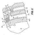
図2は心臓を逆潅流する別の典型的な方法を示す。図2では、通路32は閉塞部BLに近接する点(例えば、冠状動脈CAを通る流れに対して上流側)において冠状動脈CAと冠状静脈CVとの間に形成される。通路32は図2に示されているとおり、心筋層MYOを通して形成される。代替形態では、通路32は冠状動脈CAと冠状静脈CVとの間に直接形成される。管34は図示されているとおり通路32内に配置される。通路32は冠状動脈CAと冠状静脈CVとの間に酸素を豊富に含んだ血流を流し、冠状静脈CVに逆行性血流28を流すことができる。これにより、逆行性血流28は心筋層MYOを潅流し、冠状動脈CAの閉塞部BLにより酸素を豊富に含んだ血液が奪われる。
FIG. 2 shows another exemplary method for reverse perfusion of the heart. In FIG. 2, the
逆行性血流28を促進するために、冠状静脈CVは、図1および2に示されているとおり、位置26で少なくとも部分的に閉鎖されている。位置26は逆行性血流28の方向に対して通路の上流側にある。以下により詳細に説明されるとおり、位置26の閉塞部は完全な閉塞部であり、順行性血流(すなわち、通常方向の血流であり、逆行性流れの方向の反対である)が心搏周期全体にわたって位置26を通過するのを遮断する。他方では、この閉塞部は、心搏周期の少なくとも一部の間に、少なくとも一部の順行性血流が位置26を通過可能にする。例えば、閉塞部は、少なくとも一部の順行性血流が心搏周期全体にわたって閉塞位置を通過可能にするか、または心搏周期の別の一部の間に順行性血流が閉塞位置を通過するのを防ぐと同時に、心博周期の一部の間だけ少なくとも一部の順行性血流が閉塞位置を通過可能にする。
To promote
図1および2に示されているとおり、心臓の逆行性潅流は、例えば、左心室と冠状静脈(心室から静脈)と間または冠状動脈と冠状静脈(動脈から静脈)間に通路を形成すること、および通路の上流の位置において冠状静脈の少なくとも一部を閉鎖することにより実行される。以下の説明は、心室から静脈への逆行性潅流に関する本発明の別の態様を説明しているが、同様に動脈から静脈にも等しく適用できる。また、本発明の方法はバイパスに対して実施でき、冠状動脈内で血流を完全に遮断する閉塞部または冠状動脈CA内での血流の部分的な遮断を行う閉塞部を治療できる。 As shown in FIGS. 1 and 2, retrograde perfusion of the heart, for example, forms a passage between the left ventricle and the coronary vein (ventricle to vein) or between the coronary artery and the coronary vein (artery to vein) And closing at least a portion of the coronary vein at a location upstream of the passageway. The following description describes another aspect of the invention for retrograde perfusion from the ventricle to the vein, but is equally applicable to the artery to vein as well. In addition, the method of the present invention can be performed on a bypass to treat an occlusion that completely blocks blood flow in the coronary artery or an occlusion that partially blocks blood flow in the coronary artery CA.
典型的な態様によれば、逆行性潅流の間に冠状静脈CVの内部圧力が制御される。逆行性潅流の間の冠状静脈CVの内部圧力は十分高く、治療される心臓の虚血領域に十分な逆行性血流を供給しなければならない。例えば、圧力は、逆行性血流が静脈を通る順行性血流に打ち勝つように十分に供給され、心臓が潅流不足にならないようにしなければならない。同時に、逆行性潅流の間の冠状静脈CVの内部圧力は、冠状静脈CVへの心臓の過剰潅流および/または損傷の可能性を生じるほど高くてしてはならない。逆行性潅流の間の冠状静脈CVの内部圧力についての最適値または圧力値の範囲は、個々の患者、逆行性潅流が実行される個々の冠状静脈および冠状静脈内の逆行性潅流の個々の位置に依存する。 According to typical aspects, the internal pressure of the coronary vein CV is controlled during retrograde perfusion. The internal pressure of the coronary vein CV during retrograde perfusion must be high enough to provide sufficient retrograde blood flow to the ischemic region of the heart being treated. For example, the pressure must be supplied enough so that the retrograde blood flow overcomes the antegrade blood flow through the veins so that the heart does not become underperfused. At the same time, the internal pressure of the coronary vein CV during retrograde perfusion should not be so high as to cause the possibility of hyperperfusion and / or damage of the heart to the coronary vein CV. The optimum value or range of pressure values for the internal pressure of the coronary venous CV during retrograde perfusion depends on the individual patient, the individual coronary vein where retrograde perfusion is performed and the individual location of retrograde perfusion within the coronary vein Depends on.
したがって、例えば冠状静脈系の中間楔入圧などの内部圧力が測定され、静脈内の順行性流れの閉塞量は個々の患者に対して調整され、かつ測定された圧力に基づいて選択され、これにより、所定の圧力または圧力範囲に可能な限り近い値を達成し、その値を維持するようにされる。冠状の静脈系の平均楔入圧は、例えば通路22を形成する前に、逆行性血流を生成する前に測定される。代替形態では、平均楔入圧は通路22の形成後に測定される。冠状静脈CVの典型的な平均楔入圧を測定し、静脈に逆行性流れを生成している間の冠状静脈における目標の圧力範囲を決定する方法は、Boekstegersへの米国特許番号6,458,323に開示されている。米国特許番号6,458,323の全内容は参照により本明細書に引用したものとする。
Thus, an internal pressure, such as an intermediate wedge pressure in the coronary venous system, is measured, the amount of antegrade flow occlusion within the vein is adjusted for an individual patient and selected based on the measured pressure, This achieves a value as close as possible to the predetermined pressure or pressure range and maintains that value. The average wedge pressure of the coronary venous system is measured before generating retrograde blood flow, for example, before the
例として、圧力測定はバルーンまたは他の種類のオクルダーを静脈に挿入し、圧力変換器またはオクルダー末端の圧力測定ガイドワイヤによって圧力を測定することにより実行される。このような圧力測定技法は当業者には明らかであろう。上述の通り、圧力は通路の形成後に測定できることも考えられ、その場合、平均楔入圧を類似の技法を用いて測定して、閉鎖の所望の量および/または閉鎖の位置を決定できる。 As an example, pressure measurement is performed by inserting a balloon or other type of occluder into the vein and measuring the pressure with a pressure transducer or pressure measuring guidewire at the end of the occluder. Such pressure measurement techniques will be apparent to those skilled in the art. As discussed above, it is contemplated that the pressure can be measured after passage formation, in which case the average wedge pressure can be measured using similar techniques to determine the desired amount of closure and / or the location of the closure.
閉鎖量に加えて、閉鎖位置を選択することにより、逆行性潅流の間における冠状静脈CVの内部圧力を制御できる。例えば、同一量の閉鎖を仮定すると、通路22に近接した閉鎖位置を選択することは、逆行性潅流の間における冠状静脈CVの内部圧力を低下させる。したがって、逆行性潅流の間の血管の内部圧力は、閉鎖量の選択、閉鎖位置の選択または閉鎖量と閉鎖位置の組み合わせの選択により制御できる。
In addition to the amount of closure, the internal pressure of the coronary vein CV during retrograde perfusion can be controlled by selecting the closure position. For example, assuming the same amount of closure, selecting a closed position close to the
閉鎖量および/または閉鎖位置とは別に、例えば、圧力吸収メカニズムなどの他のメカニズムを使用して、冠状静脈の内部圧力を制御することもできる。冠状静脈の内部圧力の制御のためのこのようなメカニズムの例は、さらに詳細に以下で説明される。 Apart from the amount and / or position of closure, other mechanisms such as, for example, a pressure absorption mechanism may be used to control the internal pressure of the coronary vein. An example of such a mechanism for control of the internal pressure of the coronary vein is described in more detail below.
典型的な態様によれば、冠状静脈CVを位置26で完全に閉鎖して、心博周期全体にわたり位置26を通る順行性血流を遮断できる。図3は冠状静脈を完全に閉鎖するための閉鎖装置の典型的な実施形態である。図示されるとおり、閉鎖装置30は完全閉鎖移植片35の形態であり、例えば、ステントのような構造を有し、位置26で冠状静脈CVの内腔25内に配置される。完全な閉鎖植片35は冠状静脈CVの内面27と係着するように構成される外面37および端面39を含み、端面39は、図3に示されるとおり、例えば、通路22に面するように配置される。端面39は実質的に剛体であり、心博周期全体にわたり実質的に変形しない。したがって、完全閉鎖移植片35が使用される場合、逆行性潅流の間における還流静脈CVの内部圧力は通路22に対する移植片35の位置26の選択により制御される。
According to typical aspects, the coronary vein CV can be completely closed at
完全閉鎖移植片35は自己拡大性を有する。この移植片は収縮した状態でカテーテルまたはシース(図示せず)を通して位置26に送られ、カテーテルまたはシースから冠状静脈CVの内腔25内に押し出される。カテーテルまたはシースから押し出されると、完全閉鎖移植片35は拡大して、移植片の外面37を冠状静脈CVの内面27に係着させる。代替形態では、移植片はバルーン形状で膨張可能であり、例えばバルーンカテーテルを通して送られる。
The fully closed
移植片35は実質的に中空構造とするかまたは中実構造とすることもできると考えられる。どちらの場合でも、移植片35は移植片35を通る流れを遮断する端面39を有する。当業者は、不浸透性の端面39を移植片35のどちらかまたは両方の端部に配置できることを理解するであろう。
It is contemplated that the
内腔25内の位置26に移植片35を固定することを助けるため、移植片35に取付メカニズムを設けることができる。図3に示されるように、取付メカニズムは外面37から突き出る複数のピン40の形状である。ピン40の代替または追加として、移植片35は、その外面の周囲にカラー、フランジ、タブ、羽枝または他の類似の取付メカニズムを有し、静脈内の位置における移植片35の保持を助ける。
An attachment mechanism may be provided on the
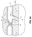
図4Aおよび4Bは、冠状静脈内の内腔25に配置される完全閉鎖移植片の別の典型的な実施形態である。図4Aおよび4Bに示される完全閉鎖移植片45は、端面49を除いて図3に図示されている実施形態と実質的に同一である。実質的に剛体ではなく、端面49は柔軟で、端面49の変形が可能である。例えば、拡張期の間、図4Aの点線と参照符号42により示されているとおり、端面49は、移植片45の反対側の端部の方向に変形し、それにより、通路22から冠状静脈CVに流れ込む血流の一部を収容する。この変形により、、冠状静脈CV内の一部の順行性血流が、通路22の上流の、位置26に向かって流れ、さらに、静脈の完全な閉鎖により冠状静脈CV内に蓄積される圧力の一部を吸収する。他方では、心収縮期の間は、端面49はその本来の形状を復元する。
FIGS. 4A and 4B are another exemplary embodiment of a fully closed graft placed in
端面49の変形は、逆行性潅流の間における冠状静脈CVの内部圧力を制御するメカニズムを提供する。したがって、柔軟な端面49を備える完全閉鎖移植片45が使用される場合、逆行性潅流の間における冠状静脈CVの内部圧力は、通路22に対する位置26を選択すること、および/または、端面49の適切な柔軟性、したがって変形の割合を選択することにより制御できる。図3の典型的な実施形態と同様に、完全閉鎖移植片45は自己拡大性があり、例えば、外面47から突き出る複数のピン40および/または他の適切な取付メカニズムのような、取付メカニズムを含む。自己拡大であることのほかに、図3、4Aおよび4Bの移植片はバルーンまたは他の拡大装置により拡大できることも考えられる。
The deformation of the
さらに、図5Aおよび5Bには、そこを通る逆行性血流を生成する冠状静脈を閉鎖する装置の別の典型的な実施形態が示されている。図5Aでは、閉鎖装置50は位置26で冠状静脈CVを完全に押しつぶすように構成される複数の磁気素子52の形を取る。図5Bでは、それに対して、閉鎖装置50は位置26で冠状静脈CVを部分的に押しつぶすように構成される複数の磁気素子52の形を取る。磁気素子52は図5Aに示されるとおり、冠状静脈CVの周りの組織内に配置され、その磁気吸引力により冠状静脈CVを位置26で部分的または完全に押しつぶすことができる。
In addition, FIGS. 5A and 5B show another exemplary embodiment of a device for closing a coronary vein that produces retrograde blood flow therethrough. In FIG. 5A, the
代替または追加として、磁気素子52は冠状静脈CVの壁内に配置されるかまたは取り付けられる(図示せず)。磁気素子52の数および/または磁気強度を適切に選択して、冠状静脈CVを、所望どおり、位置26で部分的または完全に押しつぶすことができる。したがって、磁気素子52の数および/または磁気強度が冠状静脈CVを完全に押しつぶすように選択される場合(図5A)、逆行性潅流の間における冠状静脈CVの内部圧力は、通路22に対する磁気素子52の位置26を選択することにより制御できる。他方では、冠状静脈CVが部分的に押しつぶされる場合、磁気素子52により、少なくとも一部の順行性血流が位置26を通過できるようにし、磁気素子52の磁界の強さおよび/または磁気素子52の数を選択して、冠状静脈CVが押しつぶされる量を制御し、それにより逆行性潅流の間における冠状静脈CVの内部圧力を制御することができる。上述の通り、逆行性潅流の間における冠状静脈CVの内部圧力を制御するこれらの機能は、測定された内部圧力、例えば通路22の形成の前または後に冠状静脈CVの平均楔入圧に基づいて選択される。図5Aおよび5Bに示されているとおり複数の磁気素子52を使用することは、素子52が静脈中の血流と接触しないという点で有利である。これは血栓形成の危険性を低減する。
Alternatively or additionally, the
典型的な磁気素子および人体構造内に磁気素子を配置する方法は、米国特許出願公開番号2000/0091295 A1「磁性粒子を使用する治療方法および装置(Medical Treatment Method and Device Utilizing Magnetic Particles)」に開示されている。米国特許出願公開番号2000/0091295 A1の開示の全内容は参照により本明細書に引用したものとする。 Exemplary magnetic elements and methods of placing magnetic elements within a human body structure are disclosed in US Patent Application Publication No. 2000/0091295 A1, “Medical Treatment Method and Device Using Magnetic Particles”. Has been. The entire disclosure of US Patent Application Publication No. 2000/0091295 A1 is hereby incorporated by reference.
上述の通り、位置26で完全に閉鎖されるのではなく、心搏周期の少なくとも一部の間、少なくとも一部の順行性血流が位置26を通過できるように、冠状静脈CVは位置26で部分的に閉鎖される。例えば、部分的な閉鎖により、心搏周期全体にわたって少なくとも一部の順行性血流はその位置を通過できる。代替形態では、部分的な閉鎖により、少なくとも一部の順行性血流は心搏周期の一部の間に閉鎖位置を通過でき、心搏周期の別の一部の間、順行性血流が閉鎖位置を通過するのを防止できる。
As described above, the coronary vein CV is positioned 26 so that at least a portion of the antegrade blood flow can pass through the
図5Cおよび5Dは複数の磁気素子から形成された閉鎖装置の典型的な実施形態を示しており、磁気素子により心搏周期の一部の間に少なくとも一部の順行性血流が位置を通過でき、心搏周期の別の一部の間に順行性血流を遮断する。この実施形態は、数および/または磁気強度を除いて図5Aおよび5Bに図示されている実施形態と類似しており、および/または磁気素子132の位置は適切に選択され、図5Cに示されるとおり、位置26の冠状静脈CVは心搏周期の第1の部分の間に部分的に押しつぶされ、図5Dに示されるとおり心博周期の第2の部分の間に完全に押しつぶされる。例として、磁気素子132を制御することにより、冠状静脈CVが心収縮期中に完全に押しつぶされ、位置26を少なくとも一部の順行性血流が通過でき、心拡張期中に部分的に押しつぶされ、位置26の順行性血流の通過を遮断するようにする、ことが望ましい。
FIGS. 5C and 5D illustrate an exemplary embodiment of a closure device formed from a plurality of magnetic elements that position at least some antegrade blood flow during a portion of a cardiac cycle. Can pass and blocks antegrade blood flow during another part of the cardiac cycle. This embodiment is similar to the embodiment illustrated in FIGS. 5A and 5B except for number and / or magnetic strength, and / or the location of the
心博周期の様々な部分に関連付けて静脈を押しつぶすことを制御するために、磁気素子132が、例えば、心博周期の様々な部分の間、心臓に関連する電気信号により作用を受ける。代替形態では、外部制御の磁気発生源(図示せず)が磁石132に結合され、磁石132の磁気強度を心博周期の特定の部分の間に静脈を押しつぶす所望の割合に応じて変化させるように、自動または手動で駆動される。静脈を押しつぶす割合を制御し、および心博周期と静脈を押しつぶすタイミングを合わせる別の手段も使用することができ、その手段も本発明の範囲内と考えるものとする。
In order to control the crushing of veins in relation to various parts of the cardiac cycle, the
したがって、位置26に加えて、磁気素子132の数および/または磁気強度、さらに心博周期の位相に応じた磁気強度の変化を選択することにより、逆行性潅流の間における冠状静脈CVの内部圧力を制御できる。上述のとおり、逆行性潅流の間に冠状静脈CVの内部圧力を制御するこれらの様々な形態は、通路22の形成前または後に冠状静脈CVの測定された内部圧力に基づいて選択される。
Thus, in addition to
図6は、ある位置で冠状静脈を部分的に閉鎖し、その位置で順行性血流の通過を可能にする閉鎖装置の典型的な実施形態を示している。図示されているとおり、閉鎖装置60は、冠状静脈CVの内腔25内に配置されるように構成される部分的閉鎖移植片65の形を取る。部分的閉鎖移植片65は冠状静脈CVの内面27との端面69を係着するように構成された外面67を含む。端面69は通路22に面し、実質的に剛体であって、心博周期全体にわたって変形しない。代替形態では、図4Aおよび4Bに対して説明されているとおり、端面69は柔軟であり、変形が可能である。例えば、端面69は心博周期全体にわたってまたは心博周期の一部のみの間、反対側の端部の方向に変形する。後者の場合、例えば、端面69は心拡張期中および/または心収縮期中に変形するように構成される。典型的な実施形態によれば、端面69が心収縮期中に変形するように構成される場合、静脈内の心臓収縮の最大圧力を低減でき、これにより心臓壁の効果的な潅流を助ける。
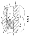
FIG. 6 illustrates an exemplary embodiment of a closure device that partially occludes a coronary vein at a location and allows passage of antegrade blood flow at that location. As shown,
さらに、部分的閉鎖移植片65は通路66を画定し、少なくとも一部の順行性血流29の通過を可能にするように構成される。この通路66は、心博周期全体にわたって一部の順行性血流が通路を通過できるように構成される。代替形態では、通路66は心博周期の少なくとも一部の間は閉じるように構成され、それにより、心博周期の一部の間のみ順行性血流が通路66を通過できるようにする。例えば、通路66は心収縮期中(例えば、移植片65を押しつぶすことにより)閉じるように構成され、心拡張期中は開いて、順行性血流がそこを通過できるように構成される。このような変形は移植片60自体の構造により生じ、この構造は、心博周期の間に静脈が受ける様々な力を考慮し、それぞれ、これらの力に応じて、それぞれ押しつぶすおよび開くように構成される。代替形態では外部の力発生源を使用して、移植片を押しつぶすおよび開くことを制御できる。移植片60と類似する構造を有する移植片を押しつぶすおよび開くことを制御するこのような装置の典型的な実施形態は、図14A、14Bおよび15を参照して以下に説明される。しかし、移植片60を押しつぶすおよび開くことを制御する他の方法もまた本発明の範囲内と見なされる。
Further, the partially closed
図6に示される実施形態では、通路66はほぼ均一の断面を有する。したがって、位置26に加えて、通路66の断面および長さを選択することにより、逆行性潅流の間における冠状静脈の内部圧力を制御できる。柔軟な端部69を有する部分的閉鎖移植片65が使用される場合、逆行性潅流の間の冠状静脈CVの内部圧力は、端部69の適切な柔軟性を選択することによっても制御できる。別の典型的な態様によれば、心博周期の様々な部分の間における通路66の(完全な閉鎖を含む)閉鎖の割合を選択することにより、冠状静脈CVの圧力を制御できる。上述の通り、移植片のこれらの様々な形態を選択して、内部圧力、例えば逆行性潅流の間における冠状静脈CVの平均楔入圧を制御でき、それらの形態は通路22の形成前および後の冠状静脈CVの測定された内部圧力に基づいて決定される。
In the embodiment shown in FIG. 6, the
部分的な閉鎖移植片65は自己拡大性を有する。代替形態では、部分的閉鎖移植片65は、バルーンなど、拡大メカニズムにより拡大可能である。通路66内に配置されるバルーン(図示せず)は、冠状静脈CVの内腔25で膨張され、部分的閉鎖移植片65を拡大する。部分的閉鎖移植片65はさらに、例えば、外面67から突き出る複数のピン40の形状の取付メカニズムまたは他の適切なメカニズムを含む。
Partially closed
図7は、ある位置で冠状静脈を部分的に閉鎖する閉鎖装置70の別の典型的な実施形態であり、心博周期の間その位置を少なくとも一部の順行性血流が通過できるようにしている。図7に図示される実施形態は、移植片75が不均一な断面を有する通路76を画定することを除いて、図6に示されている実施形態に類似している。図示されているとおり、通路76は吹き流しの形状であり、断面は通路22に最も近い端部79に比べて中間部分の断面が小さい。中間部分から端部79と反対側の端部78への通路76の断面はほぼ均一であるか、またはテーパー形であって端部78に向かって徐々に小さくなる。言うまでもなく、図7に図示されたテーパー形状は典型であり、他のテーパー形状も同様に使用できる。例えば、テーパーの方向は図7で示されているものと反対の形状が可能である。
FIG. 7 is another exemplary embodiment of a
不均一な断面を有する通路を画定する移植片の形状の閉鎖装置の別の典型的な実施形態が、図8に示されている。閉鎖装置80は、位置26で冠状静脈を部分的に閉鎖するように構成され、心博周期中その位置を少なくとも一部の順行性血流が通過できる。図8に示される実施形態では、移植片85は、断面が通路22に最も近い端部89においておよび端部89の反対側の端部88より中間部分において小さい不均一な断面を有する通路86を画定する。図示されているとおり、通路86の断面はテーパー形であり、端部88および89に向かって中間部分から徐々に大きくなる。
Another exemplary embodiment of a graft-shaped closure device that defines a passage having a non-uniform cross-section is shown in FIG. The
これらのテーパー形状は、逆行性潅流の間における冠状静脈CVの内部圧力を制御する別のメカニズムを提供する。様々なテーパー形状は、例えば、通路を通る様々な流れ抵抗を提供するように選択される。したがって、上術の様々な形態に加えて、テーパーおよび/または通路の断面の割合および/または形状をさらに別のメカニズムとして利用して、逆行性潅流の間における冠状静脈CVの内部圧力を制御できる。 These tapered shapes provide another mechanism for controlling the internal pressure of the coronary vein CV during retrograde perfusion. Different taper shapes are selected, for example, to provide different flow resistances through the passages. Thus, in addition to various forms of surgery, taper and / or passage cross-sectional proportions and / or shapes can be utilized as yet another mechanism to control coronary venous CV internal pressure during retrograde perfusion. .
図6の実施形態におけるのと同様に、図7および8に示されている閉鎖装置70および80は、心博周期全体にわたって一部の順行性血流を流すように構成される。例えば、通路76および86は心博周期全体にわたって開いたままである。代替形態では、通路76および86は、心博周期の少なくとも一部の間、例えば、押しつぶすことにより、閉じるように構成され、それにより、心博周期の一部の間のみ順行性血流が通路76および86を通過できるようにする。別の典型的な態様によれば、心博周期の様々な部分の間に通路76および86を閉鎖する(完全な閉鎖を含む)割合を選択して、冠状静脈CV内の圧力を制御できる。
As in the embodiment of FIG. 6, the
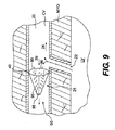
図9には、ある位置で冠状静脈を部分的に閉鎖して、心博周期中その位置を少なくとも一部順行性血流が通過できるようにする、閉鎖装置のさらに別の典型的な実施形態が示されている。図9に示される閉鎖装置90は円錐95形状の移植片である。図示されるとおり、円錐95は、その断面が、通路22に最も近い端部99から端部99と反対側の端部98の方向に徐々に小さくなる、テーパー形の通路96を有する。通路96に加えて、円錐95自体の本体により、少なくとも一部の順行性血流が位置26を通過できる。すなわち、両端の間の円錐95の外面は、多孔質のフィルター状の材料でカバーされており、一部の血液の通過を可能にする。円錐95はさらに、例えば複数のピン40などのような取付メカニズムを備え、冠状静脈CVの内腔25内にフィルター95を固定できる。
FIG. 9 shows yet another exemplary implementation of a closure device that partially occludes the coronary vein at a location so that at least partially antegrade blood flow can pass through that location during the cardiac cycle. The form is shown. The
上述の実施形態におけるのと同様に、外面のカバーの多孔性、各端部98、99の開口部のサイズ、通路22のテーパーの割合などの、円錐95の様々な形状を変更して、所望の順行性流れを得ることができ、それにより、冠状静脈内CVの圧力を制御できる。
As in the previous embodiment, various shapes of the
図11は、ある位置で冠状静脈を部分的に閉鎖して、心博周期中その位置を少なくとも一部順行性血流が通過できるようにする、閉鎖装置のさらに別の典型的な実施形態が示されている。図11は位置26での冠状静脈CVの断面図を示している。図示されているとおり、閉鎖装置110は冠状静脈CVの内腔25内に配置されるように構成される移植片115を含む。移植片115は、例えば、剛体性面119を有するかまたは実質的に剛体プラグの形状である。この方法では、血流は閉鎖装置の内部を通過できない。さらに、閉鎖装置110はバイアス部材118を含み、例えば、部材118は移植片115の外面117の全長に沿った薄い弾性または非弾性の帯などである。したがって、移植片115の外面117の一部が冠状静脈CVの内面27と係着すると同時に、外面117の別の部分と冠状静脈CVの内面27との間に空間116が形成される。この空間116により、心博周期中少なくとも一部の順行性血流が位置26を通過できる。
FIG. 11 shows yet another exemplary embodiment of a closure device that partially occludes a coronary vein at a location so that at least partially antegrade blood flow can pass through that location during a cardiac cycle. It is shown. FIG. 11 shows a cross-sectional view of the coronary vein CV at
通路22に最も近い端面119は、剛体であって、心博周期全体にわたって変形しない。代替形態では、図4Aおよび4Bに関して説明されているとおり、端面119は柔軟性があり、心博周期の少なくとも一部の間、他方の端部の方向に変形する。部分的閉鎖移植片115は自己拡大性を有する。また、部分的閉鎖移植片115は、複数のピン40などの取付メカニズムまたは他の取付メカニズムを含むことができる。
The
空間116のサイズは、バイアス部材118について様々なバイアス強度を選択することにより変更できる。したがって、上述の様々な形態に加えて、バイアス部材118のバイアス強度を選択して、逆行性潅流の間における冠状静脈CVの内部圧力を制御できる。
The size of the
図5C〜8の閉鎖装置の実施形態に関して上に説明されたとおり、例えば、図11の閉鎖装置の別の構成では、移植片115がバイアス部材118に対抗して拡大し、冠状静脈CVの内腔全体を満たすことにより、例えば、心収縮期中など心博周期の一部の間、位置26で順行性血流が通過するのを防止できる。例えば、心拡張期など心博周期の別の一部の間、冠状静脈内の圧力は、バイアス部材118が移植片115の外面の一部上を押し込むことにより、順行性血流が空間116を通過可能にし、それにより、冠状静脈CV内の圧力を制御し、逆行性潅流血流による心臓の有効な潅流を可能にする。
As described above with respect to the embodiment of the closure device of FIGS. 5C-8, for example, in another configuration of the closure device of FIG. 11, the
図12Aおよび12Bは冠状静脈を部分的に閉鎖する閉鎖装置のさらに別の典型的な実施形態を示しており、心博周期中少なくとも一部順行性血流がその閉鎖位置を通過できる。例えば、閉鎖装置140により、心収縮期中に順行性血流が位置26を通過でき、心拡張期中に順行性血流が位置26を通過するのを防止できる。図示されているとおり、装置140は冠状静脈CVの内腔25内に配置される、部分的閉鎖移植片145を含む。一般にコンジット形状の部分的閉鎖移植片145は、例えば、外面147を含むステントである。外面147の少なくとも一部は、冠状静脈CVの内面27と係着するように構成される。移植片145は端部148および149両方に開口を有する。
12A and 12B show yet another exemplary embodiment of a closure device that partially closes the coronary vein, allowing at least partially antegrade blood flow through the closed position during the cardiac cycle. For example, the
部分的閉鎖移植片145は2つの端部148、149とバイアス部材144との間に延びる内腔146を含み、例えば、比較的薄い弾性または非弾性の帯は外面147の周囲に配置されている。例えば、バイアス部材144は移植片145の中間部分の周囲に配置される。バイアス部材144のバイアス強度および弾性は、図12Aで示されているとおり、内腔146が心博周期の第1の部分の間では開き、図12Bで示されているとおり、心博周期の第2の部分の間では閉じられるように選択される。したがって、上述の他の様々な形態に加えて、バイアス部材144のバイアス強度を選択して、内腔146を通る順行性血流の量、したがって、逆行性潅流の間における冠状静脈CVの内部圧力を制御できる。
Partially closed
部分的閉鎖移植片145は自己拡大性を有する。代替形態では、部分的閉鎖移植片145はバルーン形状に膨張できおよび/または他の拡大メカニズムにより拡大できる。バイアス部材144は弾性または非弾性である。また、バルーン形状で膨張する移植片の場合、閉鎖の割合は、様々なバルーン膨張圧力に対してバイアス部材144のコンプライアンスをより大きくすることにより制御できる。言い換えると、バイアス部材144は、その弾性すなわちコンプライアンスが、移植片145を拡大するために加えられる様々な圧力に応じて様々な値を有するように構成される。これにより、バイアス部材144が、一定の割合に拡大後、実質的に非弾性体となるような弾性を有し、すなわち、所望の割合に拡大されると、それ以上に拡大しないようにすることができる。部分的閉鎖移植片145はさらに、例えば、外面147から突き出る複数のピン40などの、取付メカニズムを含む。
Partially closed
図13に示されているのと同様に、図12Aおよび12Bに示される実施形態は、心博周期全体にわたって少なくとも一部順行性血流が位置26を通過できるように変更できる。言い換えると、バイアス部材144の適切なバイアス強度の選択により、通路146は心収縮期および心拡張期中に開いた状態を保持できる。例として、バイアス部材144は、上述の通り、移植片の拡大後に実質的に変化しない、ほぼ非弾性の帯の形状にできる。
Similar to that shown in FIG. 13, the embodiment shown in FIGS. 12A and 12B can be modified to allow at least partially antegrade blood flow through
上述のように、バイアス部材144は弾性を有し、エラストマー、ゴム、シリコン、膨張金属および弾性挙動を示す他の材料であってもよい。代替形態では、バイアス部材144は実質的に非弾性であり、例えば、ステンレス鋼などの金属、例えば、ポリエチレンなどの硬質プラスチックおよび他の実質的に非弾性の材料であってもよい。典型的な実施形態では、バイアス部材144は移植片を囲む縫合糸の形状である。
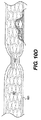
図10A〜10Dは、図10A〜10Dの移植片がバイアス部材を有さないことを除いて、図12A、12Bおよび13の実施形態に類似する限定範囲102を有する、移植片100の典型的な実施形態を示す。移植片100は、例えば、ステント101の形状であり、その構造は、静脈内でステント101が拡大するとき、ステント101の一部がステント101の他の部分103ほど拡大せず、内腔のサイズは領域102に制限されている。制限領域102を有するステント101のセル構造を形成するため、例えば、一体型チューブの電子化学エッチングおよび/またはレーザーカッティングなどの方法および拡大ステントを形成する他の方法が使用される。しかし、ステント101の制限領域102を形成するセル構造は、ステント101の非制限領域103を形成するセル構造とは異なる。制限領域102を形成するために使用される様々なセル構造は、ステント101が拡大するとき、制限領域102がステントの他の部分103ほど拡大しない。
As described above, the
FIGS. 10A-10D are
図10Bおよび10Cは拡大前のステント101を示している。拡大前には、ステント101は全長にわたりほぼ一定の直径を有する。ステント101が拡大するとき、制限されたステントのセル構造102’は拡大可能なステントのセル構造103’の形状のステントの残り部分ほど拡大しないため、内腔の大きさが減少する制限領域102を備えるステント101を実現する。典型的な実施形態においては、ステント101の拡大後の制限領域囲102の直径は、拡大前のステント101の直径とほぼ同一である。別の実施形態では、ステント101の拡大後、ステントのセル構造102’は、制限領域102が拡大前のステント101の直径よりわずかに大きい直径を有するように構成される。
10B and 10C show the
典型的な実施形態によれば、ステント101は少なくとも2つの異なるステントセル構造を有する。例えば、第1のステントセル構造102’は、例えば、図10Bで示されるとおり、ステント101の制限領域102を構成し、第2のステントのセル構造103’は、例えば、図10Cで示されるとおり、ステント101の拡大(例えば、非制限)部分103を形成する。制限領域102は、例えば、図10Aおよび10Bに示されるとおり、単一のステントセルの形状である。さらに、任意の数のステントセルを使用して、制限領域102を形成できる。さらに、ステントの全長に沿って複数の制限領域が存在し、これらの領域は、所望の相互間隔を空けて配置されている。図10Bの典型的な実施形態では、ステントセル構造102’はステント101の周囲を横切る、繰返し波形状パターンを含む。支持体104は波形状パターンを形成する隣接している足部105を接続される。支持体104は、ステントセル構造102’の半径方向の拡大を阻止または少なくとも妨害するように構成される。図10Bおよび10Cは、ステント101の非制限領域103を形成する、ステントセル構造103’の典型的な実施形態を示す。このステントセル構造103’はさらに、繰返し波形状パターンの形状のステントセルを含む。しかし、ステントセル構造103’は波形状パターンの足の間に支持体が存在せず、ステントセル構造103’は半径方向に拡大できる。図10Aから10Cの典型的な実施形態では、ステント101を形成する様々なステントセルは、接合部106により、互いに接続される。
According to an exemplary embodiment, the
図10A〜10Cに示されている特定のステントセル構造は単に典型的なものであり、移植片が他の領域に比べてある特定の領域で大きく拡大する別のセル構造を利用できるが、これも本発明の範囲内と見なされる。例えば、所望どおり、支持体の数、配置、大きさ、形状、材料および/または他の特性を変更して、制限されたステントセル構造102’のより大きなまたはより小さな拡大を実現できる。 The particular stent cell structure shown in FIGS. 10A-10C is merely exemplary, and other cell structures can be utilized in which the graft expands significantly in one particular area compared to the other. Are also considered within the scope of the present invention. For example, as desired, the number, placement, size, shape, material, and / or other characteristics of the support can be altered to achieve greater or lesser expansion of the restricted stent cell structure 102 '.
図10A〜10Cについて上で説明されたとおり、一体成形チューブから様々なステントセル構造を形成する代わりに、制限領域のステントセル構造は、非制限領域を形成するチューブから分離したチューブから形成される。この方法では、制限領域のステントセル構造は、例えば、縦に並べた構成で、溶接、接着、または非制限領域103を形成するステントのセル構造を有する他の接合メカニズムにより接合され、これにより実質的に連続したステント構造を形成する。代替形態では、ワイヤステントが使用され、ワイヤステントの一部は制限領域に形成される。これは、例えば、重なるワイヤまたは隣接するワイヤを相互に溶接または接着して、接着したワイヤの膨張を防止することにより、達成できる。
As described above for FIGS. 10A-10C, instead of forming the various stent cell structures from a monolithic tube, the restricted area stent cell structure is formed from a tube that is separate from the tube that forms the unrestricted area. . In this method, the restricted area stent cell structure is joined, for example, in a side-by-side configuration by welding, bonding, or other joining mechanism having a stent cell structure that forms an
ステント101は、ステントの形成に使用される、例えば、ステンレス鋼、形状記憶合金、金属、プラスチックおよび他の材料から形成できる。典型的な実施形態では、ステントは図10Dに示されるとおりカバー107を備えて提供される。カバー107はステント101の外面および/または内面を覆う。このようなカバー107は、例えば、伸張されたポリテトラフルオロエチレン(ePTFE)、ポリエチレンテレフタレート(PET)、ダクロンおよびステントおよび他の医療装置のために使用される他のカバーから形成される。さらに、典型的な態様では、例えば、ヘパリンなどのコーティングが覆いと併せて使用され、ステント101の内面および/または外面上のカバーの上に配置される。
The
ここで説明される他の典型的な実施形態におけるのと同様に、図10A〜10Dの移植片は自己拡大性を有するか、例えば、バルーンなど、拡大メカニズムにより拡大する。また、移植片は、羽枝、フック、タブ、ピン、縫合糸など、取付メカニズムを備えて提供され、冠状静脈内の位置で移植片を固定するのに役立つ。 As in the other exemplary embodiments described herein, the implants of FIGS. 10A-10D are self-expanding or are expanded by an expansion mechanism, such as a balloon. The graft is also provided with attachment mechanisms such as wings, hooks, tabs, pins, sutures, etc. to help secure the graft in position within the coronary vein.
さらに、ステント101の制限領域102は、ステント101の内腔が完全にまたは実質的に、心博周期の一部の間またはその全体にわたって押しつぶされるものであると、考えられる。例えば、後者の場合、ステント101は自己拡大性ステントであり、ステント101が拡大したときに、内腔がその領域で完全にまたは実質的に押しつぶされた状態を維持するような拡大しない制限領域102を備える。前者の場合、制限領域102のステント構造102’は、心博周期の別の一部の間、ステントの内腔を閉じるまたは実質的に閉じると同時に、心博周期の一部の間ステントの内腔を開けるようにわずかに拡大するように構成される。例として、制限領域の拡大は、心博周期に関連する様々な力に応じて変形するステント構造を提供することにより生じる。
Further, the restricted
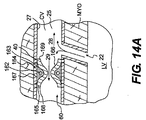
図14Aおよび14Bは冠状静脈を部分的に閉鎖する装置のさらに別の典型的な実施形態を図示しており、少なくとも一部の順行性血流が心博周期の間にその閉鎖位置を通過できる。例えば、閉鎖装置160は、心拡張期中に順行性血流が位置26を通過できるようにし、心収縮期中に順行性血流が位置26を通過できないようにすることができる。図示されているとおり、装置160は、冠状静脈CVの内腔25内に配置される部分的閉鎖移植片165を含む。図12Aおよび12Bの構成と同様に、部分的閉鎖移植片165は冠状静脈CVの内面27および2つの開口端部168、169と係着するように構成される外面167を含む。
14A and 14B illustrate yet another exemplary embodiment of a device for partially closing a coronary vein, wherein at least some antegrade blood flow passes through the closed position during the cardiac cycle. it can. For example, the
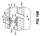
部分的閉鎖移植片165は開口端部168、169の間に延びる通路166を画定する。1つまたは複数の拡大部材164は移植片の外面167に隣接して配置される。拡大部材164は、例えば、バルーンなど、様々な形状を有する。拡大部材164の典型的な形状は、図14Aおよび14Bに示されているとおり、気泡162を含むポケット163である。ポケット163は外面167と通路166の間に形成される。代替形態では、ポケット163は移植片165の外面の一部を形成する。気泡162はポケット163を満たす適切な物質内に浮遊している。各ポケット163内の気泡162のサイズおよび/または数を選択することにより、図14Aに示されているとおり、心博周期の第1の部分の間、気泡162が少なくとも部分的に収縮して通路166を開き、図14Bに示されているとおり、心博周期の第2の部分の間、気泡が本来の形状に戻って通路166を閉じるようにできる。さらに、気泡162を含むポケット163の数ならびに移植片165の周囲のこのようなポケットの配置を選択することにより、通路166の開閉を制御できる。気泡162および/またはポケット163の数、大きさおよび配置の任意の組み合わせを選択することにより、通路166の開閉を制御または通路166の開口の割合を制御できる。例として、心博周期段階に基づいて通路166の開閉を制御するために、外部の拡大源(図示せず)を設け、気泡162を手動または自動で操作して膨張および収縮するようにできる。
Partially closed
したがって、上述の様々な形態に加えて、気泡162および/またはポケット163の数、サイズおよび配置の任意の組み合わせを選択することにより、冠状静脈CVの閉鎖量を制御し、それにより、通路166を通る順行性流れの量および逆行性潅流の間における冠状静脈CVの内部圧力を制御できる。上述のとおり、逆行性潅流の間の冠状静脈の内部圧力を制御するこれらの形態は、通路22の形成前または後に冠状静脈CVの測定された内部圧力に基づいて選択される。
Thus, in addition to the various forms described above, the amount of coronary vein CV closure can be controlled by selecting any combination of the number, size and placement of air bubbles 162 and / or
部分的閉鎖移植片165は自己拡大性を有する。代替形態では、部分的閉鎖移植片165は拡大メカニズムにより拡大できる。例えば、通路166内に配置されたバルーンを冠状静脈CVの内腔25内で膨張させて、部分的閉鎖移植片165を拡大できる。部分的閉鎖移植片165にはさらに、例えば、図14Aおよび14Bに示される複数のピン40のような取付メカニズムを設けて、冠状静脈CV内で移植片165を固定できる。
Partially closed
図15に示されるように、図14Aおよび14Bに示される実施形態を変更して、少なくとも一部の順行性血流が心博周期全体にわたって閉鎖位置を通過できるようにすることができる。言い換えると、気泡162および/またはポケット163の数、サイズおよび配置の適切な組み合わせを選択することにより、通路166は心収縮期および心拡張期の両方の間で開いた状態を維持できる。通路166が心博周期全体にわたって開いた状態を維持する実施形態では、通路166の各断面は心博周期全体にわたって同じ状態を維持するかまたは心博周期の様々な部分に関連する圧力に基づいて心博周期中に変更される。
As shown in FIG. 15, the embodiment shown in FIGS. 14A and 14B can be modified to allow at least some antegrade blood flow to pass through the closed position throughout the entire cardiac cycle. In other words, by selecting an appropriate combination of the number, size and placement of the
すでに述べたとおり、上述の閉鎖装置の様々な典型的な実施形態を用いて、逆行性潅流により心臓を治療できる。典型的な態様においては、楔入圧、例えば患者の冠状静脈の平均楔入圧は、冠状静脈の逆行性潅流の流れを確立するために、例えば酸素を豊富に含んだ血液を含む解剖学的構造と冠状静脈の間の通路を形成する前に測定される。測定された楔入圧に基づいて、目的の圧力または圧力の範囲が決定される。例えば、目的の圧力または圧力の範囲を選択して、冠状の血管内の圧力が十分高くて逆行性潅流を発生するが、心臓が過剰潅流されない程度および/または過剰圧力のために血管に損傷を与える危険性を最小化する程度に低くなるようにする。測定された圧力および/または目的の圧力または圧力の範囲に基づいて閉鎖装置を選択して、冠状静脈の圧力をほぼ目的のレベルに制御することができる。さらに、測定された圧力に基づいて、遮断の量、遮断の位置および/または圧力の吸収量などの要素を決定して、冠状血管の圧力を所定の目的レベルに制御でき、これら要素を用いて、移植のために選択される様々な特性を有するものを複数の閉鎖装置から決定できる。このように、各患者に対して使用される閉鎖装置の種類および/または位置が患者の特定の要求に一致するように調整され、それにより、患者の治療を最適化できる。 As already mentioned, the heart can be treated by retrograde perfusion using various exemplary embodiments of the closure devices described above. In a typical embodiment, the wedge pressure, e.g., the mean wedge pressure of the patient's coronary vein, is used to establish a retrograde perfusion flow of the coronary vein, e.g., an anatomical that contains oxygen-rich blood. Measured before forming a passage between the structure and the coronary vein. Based on the measured wedge entry pressure, the target pressure or range of pressures is determined. For example, select the desired pressure or range of pressures so that the pressure in the coronary vessel is high enough to produce retrograde perfusion, but the extent to which the heart is not overperfused and / or damage to the vessel due to overpressure Try to be low enough to minimize the risk. A closure device can be selected based on the measured pressure and / or the target pressure or range of pressures to control the coronary vein pressure to approximately the target level. Further, based on the measured pressure, factors such as the amount of blockage, the position of the blockage and / or the amount of pressure absorbed can be determined to control the coronary pressure to a predetermined target level, and using these factors One having a variety of characteristics selected for implantation can be determined from a plurality of closure devices. In this way, the type and / or position of the closure device used for each patient can be adjusted to match the patient's specific requirements, thereby optimizing the patient's treatment.
患者の心臓を逆行潅流するために用いられシステムの典型的な実施形態は、したがって、冠状静脈の楔入圧を測定するための圧力測定装置、および冠状静脈に対して配置されるおよび冠状静脈内で少なくとも部分的に順行性の流れを遮断するように構成される少なくとも1つの移植片を含む。例として、このようなシステムは、例えば、ここに説明されている様々な閉鎖装置の形状の複数の移植片を含み、各移植片は、さまざまな方法で流れを部分的な遮断するような様々な特性を有する。 An exemplary embodiment of a system used to retroperfuse a patient's heart is therefore a pressure measuring device for measuring coronary vein wedge pressure, and a coronary vein placed and coronary At least one implant configured to at least partially block antegrade flow. By way of example, such a system includes, for example, a plurality of implants in the form of the various closure devices described herein, each implant having various configurations that partially block flow in a variety of ways. It has special characteristics.
ここに説明されている様々な実施形態は単に例示であることを理解されたい。様々な他の構造形態が想定され、冠状静脈を通る順行性血流を少なくとも部分的に遮断するための同一機能が提供される。さらに、少なくとも一部の順行性血流が位置を通過できるとして述べた閉鎖装置の実施形態は、冠状静脈CVを完全に閉鎖するようにも構成でき、心博周期全体にわたって閉鎖装置の位置を順行性血流が通過するのを防止できる。 It should be understood that the various embodiments described herein are merely exemplary. Various other structural configurations are envisioned and provide the same function to at least partially block antegrade blood flow through the coronary vein. Furthermore, embodiments of the closure device described as allowing at least some antegrade blood flow through the location can also be configured to completely close the coronary vein CV, and position the closure device throughout the entire cardiac cycle. The antegrade blood flow can be prevented from passing.
さらに、その最も広範な態様においては、本発明は、典型的な実施形態に関して述べた方法で心臓を逆行潅流することに限定されない。上述の装置および方法を使用して、様々な他の設定において流量および圧力を制御できることは、当業者には明らかである。例えば、本発明の装置および方法は心臓に関連する器官および組織範囲以外の器官および組織範囲を逆行潅流するのに役立つ。さらに、本発明の装置および方法は酸素を豊富に含む血液を含む解剖学的構造を通る静脈系の逆行性潅流と併せて説明されている。しかし、装置および方法はまた酸素を豊富に含んだ血液を含む解剖学的構造以外の発生源を通る静脈系の逆行性潅流と併せて使用できることが想定される。このような発生源は、例えば、逆行性潅流の流れを提供する、静脈系と流体連通して配置される人工の発生源または外部の発生源を含む。加えて、ここに説明されている装置および方法は、様々な器官および身体の他の部分の潅流の間の流れ制御の分野で使用でき、その場合には、様々な部分的閉鎖装置および方法を動脈系と関連付けて用いることにより、血流および/または圧力を制御できる。 Moreover, in its broadest aspect, the present invention is not limited to retroperfusion of the heart in the manner described with respect to the exemplary embodiments. It will be apparent to those skilled in the art that the devices and methods described above can be used to control flow and pressure in a variety of other settings. For example, the devices and methods of the present invention are useful for retroperfusion of organs and tissue areas other than those associated with the heart. Furthermore, the devices and methods of the present invention have been described in conjunction with retrograde perfusion of the venous system through oxygen-rich blood-containing anatomy. However, it is envisioned that the device and method can also be used in conjunction with retrograde perfusion of the venous system through sources other than oxygen rich blood anatomical structures. Such sources include, for example, artificial sources or external sources that are placed in fluid communication with the venous system to provide retrograde perfusion flow. In addition, the devices and methods described herein can be used in the field of flow control during perfusion of various organs and other parts of the body, in which case various partial closure devices and methods can be used. By using it in conjunction with the arterial system, blood flow and / or pressure can be controlled.
本発明の他の実施形態は本明細書に開示されている本発明の明細および実施の考察から当業者には明らかであろう。明細および例は単に例示であり、本発明は修正形態および変更形態を包含するものとする。 Other embodiments of the invention will be apparent to those skilled in the art from consideration of the specification and practice of the invention disclosed herein. The specification and examples are illustrative only and the present invention is intended to cover modifications and variations.
Claims (112)
測定内部圧力を決定するために冠状静脈の内部圧力を測定するステップと、
冠状静脈内に逆行性血流を流すために、血液を含む解剖学的構造体と冠状静脈との間の通路を通して血液を流すステップと、
前記測定内部圧力に基づいて、前記逆行性血流の方向に対して通路の上流の位置で冠状静脈を少なくとも部分的に閉鎖するステップと、を含む方法。 A method of treating the heart,
Measuring the internal pressure of the coronary vein to determine the measured internal pressure;
Flowing blood through a passage between an anatomical structure containing blood and the coronary vein to flow retrograde blood flow into the coronary vein;
Closing at least partially a coronary vein at a location upstream of a passage relative to the direction of retrograde blood flow based on the measured internal pressure.
測定内部圧力を決定するために静脈系の一部の内部圧力を測定するステップと、
静脈系の一部内で逆行性血流を生成するために、血液を含む解剖学的構造体と前記静脈系の一部との間の通路を通して血液を流すステップと、
前記測定内部圧力に基づいて、前記逆行性血流の方向に対して前記通路の上流の位置で静脈系の一部を少なくとも部分的に閉鎖するステップと、を含む方法。 A method of generating retrograde perfusion, comprising:
Measuring the internal pressure of a portion of the venous system to determine the measured internal pressure;
Flowing blood through a passage between an anatomical structure containing blood and a portion of the venous system to generate retrograde blood flow within a portion of the venous system;
At least partially closing a portion of the venous system at a location upstream of the passage relative to the direction of retrograde blood flow based on the measured internal pressure.
心腔と冠状静脈の間の通路を通して血液を流すことにより、冠状静脈内で逆行性の血液を流すステップと、
前記逆行性血流の方向に対して前記通路の上流の位置で冠状静脈を少なくとも部分的に閉鎖するステップとを含む、方法。 A method of treating the heart,
Flowing retrograde blood in the coronary vein by flowing blood through a passage between the heart chamber and the coronary vein;
At least partially closing a coronary vein at a location upstream of the passage relative to the direction of the retrograde blood flow.
前記測定平均楔入圧に基づいて、冠状静脈を少なくとも部分的に閉鎖することをさらに含む、請求項38に記載の方法。 To determine the measured mean wedge pressure, measure the coronary mean wedge pressure,
40. The method of claim 38, further comprising at least partially closing a coronary vein based on the measured average wedge pressure.
前記測定平均楔入圧に基づいて、前記通路の上流の前記位置を選択することをさらに含む、請求項38に記載の方法。 To determine the measured mean wedge pressure, measure the coronary mean wedge pressure,
40. The method of claim 38, further comprising selecting the position upstream of the passage based on the measured average wedge pressure.
冠状静脈の内部圧力を測定するように構成された圧力測定装置と、
冠状静脈と血液を含む解剖学的構造体の間に形成される通路の前記逆行性血流の方向に対して上流の位置で、冠状静脈に対して配置されるように構成された少なくとも1つの移植片と、を含み、
前記移植片が冠状静脈を少なくとも部分的に閉鎖するように構成された、システム。 A system used to treat the heart by generating retrograde blood flow in a coronary vein,
A pressure measuring device configured to measure the internal pressure of the coronary vein;
At least one configured to be disposed relative to the coronary vein at a location upstream from the direction of the retrograde blood flow in a passage formed between the coronary vein and an anatomical structure containing blood An implant, and
A system wherein the graft is configured to at least partially close a coronary vein.
冠状静脈と心腔の間で通路の前記逆行性血流の方向に対して上流の位置で冠状静脈内に配置されるように構成された移植片を含み、この移植片が冠状静脈を少なくとも部分的に閉鎖するように構成されている、装置。 A device used to treat the heart by generating retrograde blood flow in a coronary vein,
A graft configured to be disposed in the coronary vein at a position upstream from the direction of the retrograde blood flow in the passage between the coronary vein and the heart chamber, the graft at least partially covering the coronary vein The device is configured to be closed automatically.
静脈系の一部の内部圧力を測定するように構成された圧力測定装置と、
静脈系の一部と血液を含む解剖学的構造体の間に形成される通路の前記逆行性血流の方向に対して上流の位置で、前記静脈系の一部に対して配置されるように構成された少なくとも1つの移植片と、を含み、
記移植片が前記静脈系の一部を少なくとも部分的に閉鎖するように構成されている、システム。 A system used to generate retrograde perfusion, comprising:
A pressure measuring device configured to measure the internal pressure of a portion of the venous system;
A passage formed between a portion of the venous system and an anatomical structure containing blood, positioned upstream from the direction of the retrograde blood flow, with respect to the portion of the venous system At least one implant configured in
A system wherein the implant is configured to at least partially occlude a portion of the venous system.
Applications Claiming Priority (2)
| Application Number | Priority Date | Filing Date | Title |
|---|---|---|---|
| US10/671,581 US20050070993A1 (en) | 2003-09-29 | 2003-09-29 | Methods of retroperfusion and related devices |
| PCT/US2004/028816 WO2005032622A2 (en) | 2003-09-29 | 2004-09-28 | Methods of retroperfusion and related devices |
Publications (1)
| Publication Number | Publication Date |
|---|---|
| JP2007507290A true JP2007507290A (en) | 2007-03-29 |
Family
ID=34376163
Family Applications (1)
| Application Number | Title | Priority Date | Filing Date |
|---|---|---|---|
| JP2006533878A Withdrawn JP2007507290A (en) | 2003-09-29 | 2004-09-28 | Method and associated apparatus for generating retrograde perfusion |
Country Status (6)
| Country | Link |
|---|---|
| US (1) | US20050070993A1 (en) |
| EP (1) | EP1670384A2 (en) |
| JP (1) | JP2007507290A (en) |
| AU (1) | AU2004277875A1 (en) |
| CA (1) | CA2540358A1 (en) |
| WO (1) | WO2005032622A2 (en) |
Cited By (1)
| Publication number | Priority date | Publication date | Assignee | Title |
|---|---|---|---|---|
| JP2016539736A (en) * | 2013-12-11 | 2016-12-22 | ミラコー メディカル システムズ ゲーエムベーハー | System and method for treating cardiac tissue |
Families Citing this family (18)
| Publication number | Priority date | Publication date | Assignee | Title |
|---|---|---|---|---|
| DE19514638C2 (en) * | 1995-04-20 | 1998-06-04 | Peter Dr Med Boekstegers | Device for the selective suction and retroinfusion of a fluid from or into body veins controlled by venous pressure |
| DE102005003632A1 (en) | 2005-01-20 | 2006-08-17 | Fraunhofer-Gesellschaft zur Förderung der angewandten Forschung e.V. | Catheter for the transvascular implantation of heart valve prostheses |
| US8070802B2 (en) * | 2007-02-23 | 2011-12-06 | The Trustees Of The University Of Pennsylvania | Mitral valve system |
| US7896915B2 (en) | 2007-04-13 | 2011-03-01 | Jenavalve Technology, Inc. | Medical device for treating a heart valve insufficiency |
| US9017362B2 (en) * | 2007-06-13 | 2015-04-28 | Cook Medical Technologies Llc | Occluding device |
| BR112012021347A2 (en) | 2008-02-26 | 2019-09-24 | Jenavalve Tecnology Inc | stent for positioning and anchoring a valve prosthesis at an implantation site in a patient's heart |
| US9044318B2 (en) | 2008-02-26 | 2015-06-02 | Jenavalve Technology Gmbh | Stent for the positioning and anchoring of a valvular prosthesis |
| US20090248142A1 (en) * | 2008-03-25 | 2009-10-01 | Medtronic Vascular, Inc. | Methods, Devices and Systems for Treating Venous Insufficiency |
| US8394139B2 (en) * | 2008-08-29 | 2013-03-12 | Cook Medical Technologies Llc | Barbed anchors for wire stent |
| US8696739B2 (en) | 2008-08-29 | 2014-04-15 | Cook Medical Technologies Llc | Barbed anchor |
| BR112012029896A2 (en) | 2010-05-25 | 2017-06-20 | Jenavalve Tech Inc | prosthetic heart valve for stent graft and stent graft |
| US9414752B2 (en) | 2012-11-09 | 2016-08-16 | Elwha Llc | Embolism deflector |
| JP6563394B2 (en) | 2013-08-30 | 2019-08-21 | イェーナヴァルヴ テクノロジー インコーポレイテッド | Radially foldable frame for an artificial valve and method for manufacturing the frame |
| CN107530168B (en) | 2015-05-01 | 2020-06-09 | 耶拿阀门科技股份有限公司 | Device and method with reduced pacemaker ratio in heart valve replacement |
| EP3454795B1 (en) | 2016-05-13 | 2023-01-11 | JenaValve Technology, Inc. | Heart valve prosthesis delivery system for delivery of heart valve prosthesis with introducer sheath and loading system |
| CN110392557A (en) | 2017-01-27 | 2019-10-29 | 耶拿阀门科技股份有限公司 | Heart valve simulation |
| WO2020154661A1 (en) * | 2019-01-24 | 2020-07-30 | Neovasc Medical Ltd. | Flow modifying implants |
| WO2020163659A1 (en) * | 2019-02-08 | 2020-08-13 | NXT Biomedical | Left atrial appendage stasis reduction |
Family Cites Families (2)
| Publication number | Priority date | Publication date | Assignee | Title |
|---|---|---|---|---|
| DE19514638C2 (en) * | 1995-04-20 | 1998-06-04 | Peter Dr Med Boekstegers | Device for the selective suction and retroinfusion of a fluid from or into body veins controlled by venous pressure |
| US6953476B1 (en) * | 2000-03-27 | 2005-10-11 | Neovasc Medical Ltd. | Device and method for treating ischemic heart disease |
-
2003
- 2003-09-29 US US10/671,581 patent/US20050070993A1/en not_active Abandoned
-
2004
- 2004-09-28 CA CA002540358A patent/CA2540358A1/en not_active Abandoned
- 2004-09-28 EP EP04783151A patent/EP1670384A2/en not_active Withdrawn
- 2004-09-28 WO PCT/US2004/028816 patent/WO2005032622A2/en active Application Filing
- 2004-09-28 AU AU2004277875A patent/AU2004277875A1/en not_active Abandoned
- 2004-09-28 JP JP2006533878A patent/JP2007507290A/en not_active Withdrawn
Cited By (1)
| Publication number | Priority date | Publication date | Assignee | Title |
|---|---|---|---|---|
| JP2016539736A (en) * | 2013-12-11 | 2016-12-22 | ミラコー メディカル システムズ ゲーエムベーハー | System and method for treating cardiac tissue |
Also Published As
| Publication number | Publication date |
|---|---|
| CA2540358A1 (en) | 2005-04-14 |
| US20050070993A1 (en) | 2005-03-31 |
| AU2004277875A1 (en) | 2005-04-14 |
| WO2005032622A3 (en) | 2005-10-06 |
| WO2005032622A2 (en) | 2005-04-14 |
| EP1670384A2 (en) | 2006-06-21 |
Similar Documents
| Publication | Publication Date | Title |
|---|---|---|
| JP6689868B2 (en) | Aortic implant | |
| US10709832B2 (en) | Methods and systems for establishing retrograde carotid arterial blood flow | |
| JP2007507290A (en) | Method and associated apparatus for generating retrograde perfusion | |
| US8894681B2 (en) | Devices, systems and methods for controlling local blood pressure | |
| US6796992B2 (en) | Cerebral perfusion augmentation | |
| US6712806B2 (en) | Partial aortic occlusion devices and methods for cerebral perfusion augmentation | |
| CN113164720A (en) | Methods and techniques for establishing connections and shunts between vessels and chambers of biological structures | |
| US20060106449A1 (en) | Flow reducing implant | |
| US20100082058A1 (en) | Devices, systems and methods for controlling local blood pressure | |
| US20230293800A1 (en) | Av flow restrictors |
Legal Events
| Date | Code | Title | Description |
|---|---|---|---|
| A300 | Application deemed to be withdrawn because no request for examination was validly filed |
Free format text: JAPANESE INTERMEDIATE CODE: A300 Effective date: 20071204 |