JP2007507165A - Apparatus and method for determining gain factors of wireless communication transmission power - Google Patents
Apparatus and method for determining gain factors of wireless communication transmission power Download PDFInfo
- Publication number
- JP2007507165A JP2007507165A JP2006528049A JP2006528049A JP2007507165A JP 2007507165 A JP2007507165 A JP 2007507165A JP 2006528049 A JP2006528049 A JP 2006528049A JP 2006528049 A JP2006528049 A JP 2006528049A JP 2007507165 A JP2007507165 A JP 2007507165A
- Authority
- JP
- Japan
- Prior art keywords
- channel
- transmission
- physical
- combination
- setting
- Prior art date
- Legal status (The legal status is an assumption and is not a legal conclusion. Google has not performed a legal analysis and makes no representation as to the accuracy of the status listed.)
- Granted
Links
Images


Classifications
-
- H—ELECTRICITY
- H04—ELECTRIC COMMUNICATION TECHNIQUE
- H04W—WIRELESS COMMUNICATION NETWORKS
- H04W52/00—Power management, e.g. TPC [Transmission Power Control], power saving or power classes
- H04W52/04—TPC
- H04W52/18—TPC being performed according to specific parameters
- H04W52/22—TPC being performed according to specific parameters taking into account previous information or commands
- H04W52/225—Calculation of statistics, e.g. average, variance
-
- H—ELECTRICITY
- H04—ELECTRIC COMMUNICATION TECHNIQUE
- H04B—TRANSMISSION
- H04B7/00—Radio transmission systems, i.e. using radiation field
- H04B7/24—Radio transmission systems, i.e. using radiation field for communication between two or more posts
- H04B7/26—Radio transmission systems, i.e. using radiation field for communication between two or more posts at least one of which is mobile
- H04B7/2628—Radio transmission systems, i.e. using radiation field for communication between two or more posts at least one of which is mobile using code-division multiple access [CDMA] or spread spectrum multiple access [SSMA]
-
- H—ELECTRICITY
- H04—ELECTRIC COMMUNICATION TECHNIQUE
- H04W—WIRELESS COMMUNICATION NETWORKS
- H04W52/00—Power management, e.g. TPC [Transmission Power Control], power saving or power classes
- H04W52/04—TPC
- H04W52/06—TPC algorithms
-
- H—ELECTRICITY
- H04—ELECTRIC COMMUNICATION TECHNIQUE
- H04W—WIRELESS COMMUNICATION NETWORKS
- H04W52/00—Power management, e.g. TPC [Transmission Power Control], power saving or power classes
- H04W52/04—TPC
- H04W52/06—TPC algorithms
- H04W52/16—Deriving transmission power values from another channel
-
- H—ELECTRICITY
- H04—ELECTRIC COMMUNICATION TECHNIQUE
- H04W—WIRELESS COMMUNICATION NETWORKS
- H04W52/00—Power management, e.g. TPC [Transmission Power Control], power saving or power classes
- H04W52/04—TPC
- H04W52/18—TPC being performed according to specific parameters
- H04W52/28—TPC being performed according to specific parameters using user profile, e.g. mobile speed, priority or network state, e.g. standby, idle or non transmission
- H04W52/281—TPC being performed according to specific parameters using user profile, e.g. mobile speed, priority or network state, e.g. standby, idle or non transmission taking into account user or data type priority
-
- H—ELECTRICITY
- H04—ELECTRIC COMMUNICATION TECHNIQUE
- H04W—WIRELESS COMMUNICATION NETWORKS
- H04W52/00—Power management, e.g. TPC [Transmission Power Control], power saving or power classes
- H04W52/04—TPC
- H04W52/30—TPC using constraints in the total amount of available transmission power
- H04W52/34—TPC management, i.e. sharing limited amount of power among users or channels or data types, e.g. cell loading
-
- H—ELECTRICITY
- H04—ELECTRIC COMMUNICATION TECHNIQUE
- H04B—TRANSMISSION
- H04B1/00—Details of transmission systems, not covered by a single one of groups H04B3/00 - H04B13/00; Details of transmission systems not characterised by the medium used for transmission
- H04B1/69—Spread spectrum techniques
- H04B1/707—Spread spectrum techniques using direct sequence modulation
-
- H—ELECTRICITY
- H04—ELECTRIC COMMUNICATION TECHNIQUE
- H04W—WIRELESS COMMUNICATION NETWORKS
- H04W52/00—Power management, e.g. TPC [Transmission Power Control], power saving or power classes
- H04W52/04—TPC
- H04W52/18—TPC being performed according to specific parameters
- H04W52/24—TPC being performed according to specific parameters using SIR [Signal to Interference Ratio] or other wireless path parameters
Abstract
無線通信の送信電力を制御する装置および方法を提供する。送信電力制御のコンテクストにおいて、物理チャネルを再構成するためのゲイン係数(gain factors)と調整の決定に対処する。実装は、同時に送信される複数のチャネル(20)を使用して無線送受信ユニット(WTRU:wireless transmit receive units)(10)間で無線通信を行う通信システムと組み合わせるのが好ましい。
An apparatus and method for controlling transmission power of wireless communications are provided. In the context of transmit power control, the determination of gain factors and adjustments to reconfigure the physical channel is addressed. The implementation is preferably combined with a communication system that performs wireless communication between wireless transmit / receive units (WTRU) (10) using multiple channels (20) transmitted simultaneously.
Description
本発明は、無線通信の送信電力を制御する装置および方法に関し、特に、同時に送信される複数のチャネルを使用して無線送受信ユニット(WTRU:wireless transmit receive units)間に無線通信を実装する通信システムに関する。送信電力制御のコンテクストにおいて、物理チャネルを再構成するためのゲイン係数と調整の決定に対処する。 The present invention relates to an apparatus and method for controlling transmission power of wireless communication, and in particular, a communication system that implements wireless communication between wireless transmit / receive units (WTRUs) using a plurality of channels transmitted simultaneously. About. In the context of transmit power control, the determination of gain factors and adjustments to reconfigure the physical channel is addressed.
無線通信システムは当業者には周知である。一般に、こうしたシステムは、通信ステーション(communication stations)、すなわち相互間で無線通信信号を送信および受信する無線送信/受信ユニット(WTRU)で構成されている。システムのタイプによって、通信ステーションは通常は基地局と加入者WTRU(モバイルユニットを含む)の2種類のいずれかである。 Wireless communication systems are well known to those skilled in the art. In general, such systems are comprised of communication stations, ie, wireless transmit / receive units (WTRUs) that transmit and receive wireless communication signals between each other. Depending on the type of system, the communication station is usually one of two types: a base station or a subscriber WTRU (including a mobile unit).
無線システムのグローバルな接続性を提供するために、標準規格が作成され、実装されている。現在普及している1つの標準規格は、Global System for Mobile Telecommunications(GSM)として知られている。これは、いわゆる第2世代モバイル無線システム標準(Second Generation mobile radio system standard)(2G)と見なされており、後にはその改訂版(2.5G)が続いている。GPRS(General Packet Radio Service)とEDGE(Enhanced Data rates for Global Evolution)は、(2G)GSMネットワークで最上位の比較的高速のデータサービスを提供する、2.5G技術の具体的例である。こうした標準のそれぞれには、先行する標準規格を改善するために、機能の追加と強化が求められている。1998年1月に、European Telecommunications Standard Institute-Special Mobile Group(ETSI SMG)は、Universal Mobile Telecommunications Systems(UMTS)と呼ばれる第3世代無線システムの無線アクセススキーマに合意した。UMTS標準の高度な実装のために、1998年12月に第3世代パートナーシッププロジェクト(3GPP:Third Generation Partnership Project)が結成された。3GPPは、一般的な第3世代モバイル無線標準規格への取り組みを続けている。 Standards have been created and implemented to provide global connectivity for wireless systems. One standard that is currently popular is known as Global System for Mobile Telecommunications (GSM). This is considered the so-called Second Generation mobile radio system standard (2G), followed by its revised version (2.5G). GPRS (General Packet Radio Service) and EDGE (Enhanced Data fors for Global Evolution) are specific examples of 2.5G technologies that provide the highest, relatively high-speed data services in (2G) GSM networks. Each of these standards requires additional features and enhancements to improve the previous standards. In January 1998, the European Telecommunications Standard Institute-Special Mobile Group (ETSI SMG) agreed on a radio access schema for a third generation radio system called Universal Mobile Telecommunications Systems (UMTS). A 3rd Generation Partnership Project (3GPP) was formed in December 1998 for advanced implementation of the UMTS standard. 3GPP continues to work on general third generation mobile radio standards.
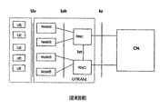
現在の3GPP仕様による一般的なUMTSシステムが図1に示されている。UMTSのネットワークアーキテクチャには、Iuとして知られるインターフェースを介してUTRAN(UMTS Terrestrial Radio Access Network)と相互接続されるコアネットワーク(CN:Core Network)が含まれる。Iuインターフェースは、現在公的に入手可能な3GPP仕様のドキュメントで詳細に定義されている。UTRANは、3GPPではユーザ装置(UE:User Equipment)として知られる無線送受信ユニット(WTRU)を介してUuとして知られる無線インターフェース経由でユーザに無線通信サービスを提供するように構成されている。UTRANは、1つまたは複数の無線ネットワークコントローラ(RNC:Radio Network Controller)および3GPPではNode Bとして知られる基地局を備えており、全体としてUEによる無線通信の地理上のカバリッジを提供する。1つまたは複数のNode Bは、3GPPではIubとして知られるインターフェースを経由してそれぞれのRNCに接続する。UTRANには、異なるRNCに接続するNode Bのいくつかのグループが含まれていてもよい。例えば、図1の例には2つのグループが示されている。UTRANに複数のRNCが提供されている場合に、RNC間の通信はIurインターフェースを経由して行われる。 A typical UMTS system according to the current 3GPP specification is shown in FIG. The UMTS network architecture includes a core network (CN) that is interconnected with UTRAN (UMTS Terrestrial Radio Access Network) via an interface known as Iu. The Iu interface is defined in detail in 3GPP specification documents that are now publicly available. UTRAN is configured to provide wireless communication services to users via a wireless interface known as Uu via a wireless transceiver unit (WTRU) known as User Equipment (UE) in 3GPP. UTRAN comprises one or more radio network controllers (RNCs) and a base station known as Node B in 3GPP, and provides a geographical coverage of radio communications by the UE as a whole. One or more Node Bs connect to each RNC via an interface known as Iub in 3GPP. UTRAN may include several groups of Node Bs that connect to different RNCs. For example, two groups are shown in the example of FIG. When a plurality of RNCs are provided to UTRAN, communication between RNCs is performed via an Iur interface.
ネットワークコンポーネントの外部の通信は、ユーザレベルではNode BによってUuインターフェースを介して行われ、ネットワークレベルではCNによって外部システムへの様々なCN接続を介して行われる。 Communication external to the network component is performed at the user level by the Node B via the Uu interface, and at the network level by the CN via various CN connections to external systems.
CNは、情報をその正しいあて先にルーティングする役割を果たす。例えば、CNはNode Bのいずれかを介してUMTSが受信するUEからの音声トラフィックを公衆交換電話網(PSTN)にルーティングしてもよいし、インターネットに割り当てられたパケットデータにルーティングしてもよい。3GPPにおいて、CNは、1)サービング(serving)General Packet Radio Service(GPRS)サポートノード、2)ゲートウェイGPRSサポートノード、3)(border gateway)、4)VLR(visitor location register)、5)移動通信交換局、6)ゲートウェイ移動通信交換局(gateway mobile services switching center)の6つの主要コンポーネントを備えている。サービングGPRSサポートノードを使用すると、インターネットなどのパケット交換ドメインにアクセスできる。ゲートウェイGPRSサポートノードは、他のネットワークに接続するためのゲートウェイノードである。他のオペレータのネットワークまたはインターネットに送信されるすべてのデータトラフィックは、ゲートウェイGPRSサポートノードを通過する。ボーダーゲートウェイは、ファイアウォールとして動作し、ネットワーク外部からの侵入者によるネットワーク領域内の加入者への攻撃を防止する。VLRは、サービスを提供するために必要な加入者データの最新のサービングネットワークコピーである。この情報は、初めにモバイル加入者を管理するデータベースから取得される。移動通信交換局は、UMTS端末からネットワークへの「回線交換」接続を担当する。ゲートウェイ移動通信交換局は、加入者の現在の位置に基づいて要求されるルーティング機能を実現する。ゲートウェイモバイルサービス交換センターは、外部ネットワークの加入者からの接続要求を受け取り、管理する。 The CN is responsible for routing information to its correct destination. For example, the CN may route voice traffic from the UE received by the UMTS via any of the Node Bs to the public switched telephone network (PSTN) or to packet data assigned to the Internet. . In 3GPP, CN is 1) Serving General Packet Radio Service (GPRS) support node, 2) Gateway GPRS support node, 3) (boarder gateway), 4) VLR (visitor location register), 5) Mobile communication exchange 6) It has six main components: gateway mobile services switching center. The serving GPRS support node can be used to access a packet switched domain such as the Internet. The gateway GPRS support node is a gateway node for connecting to another network. All data traffic sent to the other operator's network or the Internet passes through the gateway GPRS support node. The border gateway operates as a firewall and prevents an intruder from outside the network from attacking the subscriber in the network area. A VLR is an up-to-date serving network copy of subscriber data required to provide a service. This information is initially obtained from a database that manages mobile subscribers. The mobile switching center is responsible for the “circuit switched” connection from the UMTS terminal to the network. The gateway mobile switching center implements the required routing function based on the current location of the subscriber. The gateway mobile service switching center receives and manages connection requests from external network subscribers.
RNCは、一般にUTRANの内部機能を制御する。RNCは、Node BとのUuインターフェース接続を経由したローカルコンポーネントと、CNと外部システムとの接続を経由した外部サービスコンポーネントとを備える通信のための中継サービスも提供する(例えば、国内のUMTSの携帯電話からの海外呼び出し)。 The RNC generally controls the internal functions of UTRAN. The RNC also provides a relay service for communication comprising a local component via a Uu interface connection with the Node B and an external service component via a connection between the CN and an external system (for example, a domestic UMTS mobile phone). Overseas call from phone).
一般に、RNCは複数の基地局を監視し、Node Bが提供する無線サービスの対象となる地理上の領域内の無線リソースを管理し、さらにUuインターフェースの物理的無線リソースを制御する。3GPPでは、RNCのIuインターフェースはCNへの2つの接続、つまり1つはパケット交換ドメイン、もう1つは回路交換ドメインへの接続を提供する。RNCのその他の重要な機能には、機密保護と整合性の保護がある。 In general, the RNC monitors a plurality of base stations, manages radio resources in a geographical area targeted for radio services provided by the Node B, and controls physical radio resources of the Uu interface. In 3GPP, the RNC Iu interface provides two connections to the CN, one for the packet switched domain and one for the circuit switched domain. Other important functions of the RNC include confidentiality and integrity protection.
一般に、Node Bなどの基地局の主な機能は、基地局のネットワークとWTRUとの間に無線接続を提供することである。通常、基地局から発信される共通チャネル信号(common channel signal)によって、接続されていないWTRUは基地局のタイミングに同期することができる。3GPPにおいて、Node BはUEとの物理的な無線接続を行う。Node Bは、RNCからIubインターフェースを経由して信号を受信する。RNCは、Node BがUuインターフェースを経由して送信する無線信号を制御する。3GPP通信システムのUu無線インターフェースはユーザデータを送信し、UEとNode Bとの信号伝達を行う送信チャネル(TrCH:Transport Channels)を使用する。チャネルは、一般に共有チャネル(Shared Channels)、すなわち同時に複数のUEに使用できるチャネルとして、または専用チャネル(DCH:dedicated channel)、すなわち無線通信の間に特定のUEで使用するために割り当てられるチャネルとして指定される。 In general, the main function of a base station such as Node B is to provide a wireless connection between the base station network and the WTRU. Normally, a non-connected WTRU can be synchronized with the timing of the base station by a common channel signal transmitted from the base station. In 3GPP, the Node B performs a physical radio connection with the UE. The Node B receives a signal from the RNC via the Iub interface. The RNC controls a radio signal transmitted by the Node B via the Uu interface. The Uu radio interface of the 3GPP communication system uses a transmission channel (TrCH: Transport Channels) that transmits user data and performs signaling between the UE and the Node B. Channels are generally shared channels (Shared Channels), i.e., channels that can be used simultaneously by multiple UEs, or dedicated channels (DCH), i.e., channels that are allocated for use by a particular UE during wireless communication. It is specified.
多くの無線通信システムにおいて、適応的な送信電力制御アルゴリズムが使用され、WTRUの送信電力を制御している。このようなシステムでは、多くのWTRUが同じ無線周波数スペクトルを共有できる。特定の通信を受信する場合は、同じスペクトルで送信される他のすべての通信がこの特定の通信への干渉の原因となる。結果として、1つの通信の送信電力レベルを上げることによってそのスペクトル内にある他のすべての通信の信号品質が低下する。しかし、送信電力レベルを極度に下げると、受信機の信号対干渉比(SIR:signal to interference ratio)で測定されるように、望ましくない受信信号品質となってしまう。 In many wireless communication systems, adaptive transmit power control algorithms are used to control the WTRU transmit power. In such a system, many WTRUs can share the same radio frequency spectrum. When receiving a particular communication, all other communications transmitted in the same spectrum will cause interference to this particular communication. As a result, increasing the transmission power level of one communication degrades the signal quality of all other communications in the spectrum. However, extremely low transmission power levels result in undesirable received signal quality, as measured by the receiver's signal to interference ratio (SIR).
無線通信システムの出力電力を制御する様々な方法は当業者には周知である。無線通信システムのためのオープンループ電力制御システムの例は、図2に示されている。こうしたシステムの目的は、フェージング伝搬チャネル(fading propagation channel)と時間によって変動する干渉によって送信機の出力が最小になる場合に、離れた端末で許容できる品質のデータを受信することを保証しながら、送信電力を迅速に変化させることである。 Various methods for controlling the output power of a wireless communication system are well known to those skilled in the art. An example of an open loop power control system for a wireless communication system is shown in FIG. The purpose of such a system is to ensure that a remote terminal receives acceptable quality data when the transmitter output is minimized due to fading propagation channels and time-varying interference, while It is to change the transmission power quickly.
第3世代パートナーシッププロジェクト(3GPP)の時分割多重(TDD:Time Division Duplex)システムと周波数分割多重(FDD)システムなどの通信システムにおいて、データ転送速度を変更できる共有チャネルと専用チャネルを組み合わせて、送信が行われる。3GPPワイドバンドCDMA(WCDMA:wideband CDMA)システムでは、電力制御がリンクアダプテーション方法として使用される。DPCHの送信電力を調整し、最小の送信電力レベルでサービス品質(QoS:quality of service)を実現する、したがってシステム内の干渉レベルを制限する動的な電力制御は、専用物理チャネル(DPCH:dedicated physical channel)に適用される。 In a communication system such as a Time Division Duplex (TDD) system and a Frequency Division Multiplex (FDD) system of the 3rd Generation Partnership Project (3GPP), transmission is performed by combining a shared channel that can change the data transfer rate and a dedicated channel. Is done. In 3GPP wideband CDMA (WCDMA) systems, power control is used as the link adaptation method. Dynamic power control that adjusts the transmission power of the DPCH to achieve quality of service (QoS) at the minimum transmission power level, and thus limits the interference level in the system, is a dedicated physical channel (DPCH). (physical channel).
電力制御の1つの慣例的なアプローチは、送信電力制御を個別のプロセスに分割することであり、外部ループ電力制御(OLPC:outer loop power control)および内部ループ電力制御(ILPC:inner loop power control)と呼ばれる。電力制御システムは、一般に内部ループが開いているか閉じているかによってオープンまたはクロ−ズドと言われる。通常、アップリンク通信を行う3GPPシステムにおいて、両方のタイプのシステムの外部ループはクロ−ズドループである。図2に示すWCDMAオープンループタイプのシステムの例の内部ループはオープンループである。 One conventional approach to power control is to divide transmit power control into separate processes, such as outer loop power control (OLPC) and inner loop power control (ILPC). Called. A power control system is commonly referred to as open or closed depending on whether the inner loop is open or closed. Typically, in 3GPP systems with uplink communication, the outer loop of both types of systems is a closed loop. The inner loop of the example of the WCDMA open loop type system shown in FIG. 2 is an open loop.
外部ループの電力制御において、特定の送信機の出力レベルは通常はターゲットSIR値などの目標値に基づいている。受信機では、その送信信号を受信するときに、受信信号の品質が測定される。3GPPシステムにおいて、送信された情報は送信ブロック(TB:transport block)単位で送信され、受信した信号の品質はブロックエラーレート(BLER:block error rate)ベースで監視できる。BLERは、受信機で通常はデータの巡回冗長検査(CRC:cyclic redundancy check)によって評価される。この評価されたBLERは、ターゲットBLER、チャネル上の様々なタイプのデータサービスに関するQoS要求条件の代表値など、ターゲット品質要求条件と比較される。測定された受信信号品質に基づいて、ターゲットSIR調整制御信号が生成され、ターゲットSIRはこうした調整制御信号に応じて調整される。 In outer loop power control, the output level of a particular transmitter is usually based on a target value such as a target SIR value. In the receiver, when the transmission signal is received, the quality of the received signal is measured. In the 3GPP system, transmitted information is transmitted in units of a transport block (TB), and the quality of a received signal can be monitored on a block error rate (BLER) basis. The BLER is typically evaluated at the receiver by a cyclic redundancy check (CRC) of the data. This evaluated BLER is compared to target quality requirements, such as target BLER, representative values of QoS requirements for various types of data services on the channel. Based on the measured received signal quality, a target SIR adjustment control signal is generated, and the target SIR is adjusted in response to the adjustment control signal.
内部ループの電力制御において、受信機は受信信号品質の測定値(SIRなど)をしきい値と比較する。SIRがしきい値を上回る場合は、出力レベルを下げる送信電力コマンド(TPC:transmit power command)が送信される。SIRがしきい値を下回る場合は、出力レベルを上げるTPCが送信される。通常、TPCは送信機への専用チャネル内のデータで多重化されて送信される。送信機は、受信したTPCに応じてその送信電力レベルを変更する。 In inner loop power control, the receiver compares a received signal quality measurement (such as SIR) with a threshold. When the SIR exceeds the threshold value, a transmission power command (TPC) that lowers the output level is transmitted. If the SIR is below the threshold, a TPC that increases the output level is transmitted. Usually, the TPC is multiplexed and transmitted with data in a dedicated channel to the transmitter. The transmitter changes its transmission power level according to the received TPC.
従来、3GPPシステムの外部ループ電力制御アルゴリズムは、BLERとSIRとの固定のマッピングを使用し、特定のチャネル条件を仮定した上で、各CCTrCH(coded composite transport channel)に対して要求されたターゲットBLERに基づいて、初期ターゲットSIRを設定する。CCTrCHは、複数の送信チャネル(TrCH:transport channel)を多重化することによって、物理無線チャネル上で様々なサービスを(サービスごとに独自のTrCH上で)送信するために一般的に採用されている。CCTrCHベースでBLERレベルを監視するために、検討しているCCTrCHに多重化される送信チャネルの中から参照送信チャネル(RTrCH:reference transport channel)を選択してもよい。 Conventionally, the outer loop power control algorithm of the 3GPP system uses a fixed mapping between BLER and SIR and assumes a specific channel condition, and then requires a target BLER required for each CCTrCH (coded composite transport channel). Based on the above, an initial target SIR is set. CCTrCH is commonly adopted to transmit various services (on a unique TrCH for each service) on a physical radio channel by multiplexing a plurality of transmission channels (TrCH). . In order to monitor the BLER level on a CCTrCH basis, a reference transmission channel (RTrCH: reference transport channel) may be selected from the transmission channels multiplexed on the CCTrCH under consideration.
3GPPシステムのWTRUで送信される専用チャネルのアップリンク電力制御は、図2に示す例のようにクローズしている外部ループとオープンの内部ループで構成される。クロ−ズしている外部ループは、特定のWTRUで実行されるアップリンク送信のSIRターゲットを決定する役割を果たす。SIRターゲットの初期値は、制御RNC(C−RNC:Controlling RNC)によって決定され、さらにアップリンクCCTrCH品質の測定値に基づいてサービングRNC(S−RNC:Serving RNC)によって調整されてもよい。ここで、S−RNCはSIRターゲットの更新をWTRUに送信する。オープンの内部ループは、フレームごとにサービングセルのP−CCPCH受信信号コード出力(RSCP:received signal code power)を測定し、Node BとWTRUとの間のパスロスを計算するWTRUによるアップリンク送信電力を計算する。パスロスとSIRターゲットおよびUL CCTrCHのULタイムスロット干渉信号コード出力(ISCP:interference signal code power)のUTRAN送信値に基づいて、WTRUは専用物理チャネル(PDPCH)の送信電力を計算する。 The uplink power control of the dedicated channel transmitted by the WTRU of the 3GPP system is configured by a closed outer loop and an open inner loop as in the example shown in FIG. The closing outer loop is responsible for determining the SIR target for uplink transmissions performed at a particular WTRU. The initial value of the SIR target is determined by the control RNC (C-RNC: Controlling RNC) and may be further adjusted by the serving RNC (S-RNC: Serving RNC) based on the measured value of the uplink CCTrCH quality. Here, the S-RNC sends an update of the SIR target to the WTRU. An open inner loop measures the P-CCPCH received signal code power (RSCP) of the serving cell for each frame and calculates the uplink transmission power by the WTRU that calculates the path loss between the Node B and the WTRU. To do. The WTRU calculates the transmit power of the dedicated physical channel (P DPCH ) based on the path loss, the SIR target, and the UL time slot interference signal code output (ISPP) UTRAN transmission value of the UL CCTrCH.
さらに、CCTrCHの個々のDPCH(DPCHi)は、様々なDPCHで使用する様々な拡散係数を補償する重み係数γiによって、個々に重み付けされる。さらに、各タイムスロットのDPCHは、複雑な加算を使用して結合される。 Furthermore, the individual DPCHs (DPCHi) of the CCTrCH are individually weighted by weighting factors γi that compensate for the various spreading factors used in the various DPCHs. Furthermore, the DPCH for each time slot is combined using complex addition.
物理チャネルを結合した後で、CCTrCHのゲイン係数βが適用される。ゲイン係数は、CCTrCHに割り当てられた様々なTFCの送信電力要求条件の差を補償する。つまり、各TFCはコードコンポジット送信チャネル(CCTrCH:Coded Composite Transport Channel)の送信チャネルのそれぞれからのデータの様々な組合せを表している。個々の組合せによって、CCTrCH内の各TrCHに適用する様々な量の繰り返し(repetition)またはパンクチャリング(puncturing)が得られる。パンクチャリング/繰り返しは特定の信号対ノイズ比(Eb/No)を得るために必要な送信電力に影響を及ぼすので、適用するゲイン係数は使用するTFCによって変わる。すなわち、CCTrCHのTFCごとにゲイン係数は独自のものである。ゲイン係数βjの値は、CCTrCHのj番目のTFCに適用される。このプロセスは図3に概念的に示されており、例えば、専用チャネルDPCH1とDPCH2はTrCHのj番目のTFCのデータを搬送する。 After combining the physical channels, the CCTrCH gain factor β is applied. The gain factor compensates for differences in transmission power requirements of various TFCs assigned to CCTrCH. That is, each TFC represents various combinations of data from each of the transmission channels of the code composite transmission channel (CCTrCH: Coded Composite Transport Channel). Individual combinations result in varying amounts of repetition or puncturing applied to each TrCH within the CCTrCH. Since the puncturing / repetition affects the transmission power required to obtain a specific signal-to-noise ratio (Eb / No), the applied gain factor varies depending on the TFC used. That is, the gain coefficient is unique for each TFC of CCTrCH. The value of the gain coefficient βj is applied to the jth TFC of CCTrCH. This process is conceptually illustrated in FIG. 3, for example, dedicated channels DPCH1 and DPCH2 carry data for the jth TFC of TrCH.
βjの値は、TFCjごとに明示的にWTRUに送信できる。または、RNC内の無線リソース制御(RRC:radio resource control)によって、UEが、明示的に送信された参照TFCの値に基づいて、TFCごとのβjを計算する必要があることを示すこともできる。この計算は、従来、レートマッチングパラメータ(rate matching parameters)と、リソース単位が例えば1つのSF16コードとして定義された場合は、指定されたTFCjおよび参照TFCに必要なリソース単位の数に基づいて行われる。SF 16コードのみによる物理チャネル設定の場合は、リソース単位(RU)の数がコードの数に等しくなる。すべてSF 16ではないコードによる設定の場合は、RUの数がSF 16コードの数に等しくなる。個々の拡散係数の等価性は、1 SF8コード=2 RU、1 SF4コード=4 RU、1 SF2コード=8 RU、1 SF 1コード=16 RUである。
The value of βj can be explicitly sent to the WTRU for each TFCj. Alternatively, radio resource control (RRC) in the RNC may indicate that the UE needs to calculate βj for each TFC based on the value of the explicitly transmitted reference TFC. . This calculation is conventionally performed based on rate matching parameters and the number of resource units required for the specified TFCj and reference TFC when the resource units are defined as one SF16 code, for example. . In the case of physical channel setting using only
第1の方法は「送信されたゲイン係数」、第2の方法は「計算されたゲイン係数」と呼ばれる。 The first method is called “transmitted gain factor” and the second method is called “calculated gain factor”.
加入者WTRUで参照TFCに基づいて係数βを計算する従来の方法は、次のようにして提供される。 A conventional method for calculating the coefficient β based on the reference TFC at the subscriber WTRU is provided as follows.
βrefは送信された参照TFCのゲイン係数を表し、βjはj番目のTFCのゲイン係数を表すものとする。 βref represents the gain coefficient of the transmitted reference TFC, and βj represents the gain coefficient of the j-th TFC.
変数 variable
![]()
![]()
を定義する。 Define
ただし、RMiは送信チャネルiの半静的(semi−static)レートマッチング属性、Niは送信チャネルiの無線フレームセグメンテーションブロック(radio frame segmentation block)から出力されたビットの数であり、参照TFC内のすべての送信チャネルiについて合計する。 Where RMi is the semi-static rate matching attribute of transmission channel i, Ni is the number of bits output from the radio frame segmentation block of transmission channel i, and is in the reference TFC Sum for all transmission channels i.
同様に、変数 Similarly, the variable
![]()
![]()
を定義する。 Define
ここで、j番目のTFC内のすべての送信チャネルiについて合計する。 Here, the total is performed for all transmission channels i in the j-th TFC.
さらに、変数 In addition, the variable
![]()
![]()
を定義する。 Define
ここで、SFiはDPCHiの拡散係数であり、参照TFC内で使用するすべてのDPCHiについて合計する。 Here, SF i is a diffusion coefficient of DPCHi, and is summed up for all DPCHi used in the reference TFC.
同様に、変数 Similarly, the variable
![]()
![]()
を定義する。 Define
ここで、j番目のTFC内で使用するすべてのDPCHiについて合計する。 Here, the summation is performed for all DPCHi used in the j-th TFC.
j番目のTFCのゲイン係数βjは、従来は次のように計算される。 The gain coefficient βj of the j-th TFC is conventionally calculated as follows.

参照TFCを送信する代わりに、各TFCのゲイン係数の値をRNC内で決定し、WTRUに送信することもできる。 Instead of sending a reference TFC, the value of the gain factor for each TFC can be determined in the RNC and sent to the WTRU.
しかしながら、現在の標準規格ではWTRUに送信する送信されたゲイン係数の値を決定する方法を定義していない。発明者は、TFCのゲイン係数を、参照TFCに適用できるゲイン係数に比例させることによって、TFCのゲイン係数の計算を改善できることを認識している。この改善は、「送信されたゲイン係数」と「計算されたゲイン係数」の両方に適用できる。 However, current standards do not define a method for determining the value of the transmitted gain factor to be transmitted to the WTRU. The inventor has recognized that the TFC gain factor calculation can be improved by making the TFC gain factor proportional to the gain factor applicable to the reference TFC. This improvement can be applied to both “transmitted gain factor” and “calculated gain factor”.
従来のシステムにおいて発生する別の問題は、再構成(reconfiguration)中のアップリンク電力制御の維持に関連する。物理チャネルの再構成においてCCTrCHに使用する拡散係数を変更する場合に、各TFCのパンクチャリング/繰り返しは再構成の前と後で異なってもよい。従来、ゲイン係数はTFCの中の相対的なパンクチャリング/繰り返しによって変わるので、再構成の前に使用するゲイン係数は再構成の後のパンクチャリング/繰り返しに対応しなくてもよい。 Another problem that occurs in conventional systems is related to maintaining uplink power control during reconfiguration. When changing the spreading factor used for CCTrCH in physical channel reconfiguration, the puncturing / repetition of each TFC may be different before and after reconfiguration. Conventionally, gain factors change with relative puncturing / repetition in the TFC, so the gain factors used before reconstruction may not correspond to puncturing / repetition after reconstruction.
発明者は、このことによってTFCの新しいパンクチャリング/繰り返しに基づいて再収束するための電力制御の必要性が発生することを認識している。パンクチャリング/繰り返しに関連する再構成の後で、同じ出力レベルによって得られたものでない新しいゲイン係数が計算または選択された場合は、再収束することが必要である。再収束の必要性を軽減するために、発明者は次の作業が有効であることを認識している。
・ 再構成の前と後に適切な参照TFCと参照ゲイン係数値を選択する。
・ 再構成の後で使用する新しい参照TFCを選択する(参照ゲイン係数は再構成の前と後で同じに維持される)。
・ 再構成の後で使用する新しい参照ゲイン係数を選択する(参照TFCは再構成の前と後で同じに維持される)。および/または、
・ 再構成の後で使用する新しいSIRターゲットを選択する。
The inventor has recognized that this creates a need for power control to reconverge based on new puncturing / repetition of the TFC. After a reconstruction associated with puncturing / iteration, if a new gain factor is calculated or selected that is not obtained by the same power level, reconvergence is necessary. To alleviate the need for reconvergence, the inventor has recognized that the following work is effective.
Select appropriate reference TFC and reference gain factor values before and after reconstruction.
Select a new reference TFC to use after reconstruction (reference gain factor is kept the same before and after reconstruction).
Select a new reference gain factor to use after reconstruction (reference TFC is kept the same before and after reconstruction). And / or
Select a new SIR target to use after reconfiguration.
無線通信の送信電力を制御するためのゲイン係数を決定する装置および方法を提供する。実装は、同時に送信されている複数のチャネルを使用して無線送受信ユニット(WTRU)間において無線通信を行う通信システムと組み合わせるのが好ましい。 An apparatus and method for determining a gain factor for controlling transmission power of wireless communications is provided. The implementation is preferably combined with a communication system that performs wireless communication between wireless transmit / receive units (WTRUs) using multiple channels being transmitted simultaneously.
本発明の1つの態様において、選択されたチャネルの組合せでデータを搬送するフォワードコンポジットチャネル(forward composite channel)を経由して、信号を送信するWTRUの送信電力を制御する方法が提供される。この方法において、WTRUは、フォワードチャネルを経由して受信したデータ信号に基づいて計算されたターゲットメトリックス(target metrics)の関数として、フォワードチャネルの出力電力調整を行うように構成されている。参照ゲイン係数βrefは、参照となるチャネルの組合せに対して決定される。フォワードコンポジットチャネルを経由してデータを送信するためのチャネルの組合せが選択される。選択されたチャネルの組合せが参照となるチャネルの組合せと同じでない場合は、選択されたチャネルの組合せに対するゲイン係数βは、選択されたチャネルの組合せに対するゲイン係数βが参照ゲイン係数βrefに比例するように計算される。選択されたチャネルの組合せに対するゲイン係数βは、さらにフォワードコンポジットチャネルを経由してデータ信号を送信する場合に、フォワードチャネルの出力電力調整を行うときに、選択されたチャネルの組合せを使用するフォワードコンポジットチャネルに適用される。 In one aspect of the invention, a method is provided for controlling transmission power of a WTRU that transmits a signal via a forward composite channel that carries data in a selected combination of channels. In this method, the WTRU is configured to adjust the output power of the forward channel as a function of target metrics calculated based on data signals received via the forward channel. The reference gain coefficient βref is determined for a reference channel combination. A combination of channels for transmitting data via the forward composite channel is selected. If the selected channel combination is not the same as the reference channel combination, the gain factor β for the selected channel combination is such that the gain factor β for the selected channel combination is proportional to the reference gain factor βref. Is calculated. The gain coefficient β for the selected channel combination is a forward composite that uses the selected channel combination when adjusting the output power of the forward channel when a data signal is further transmitted via the forward composite channel. Applied to the channel.
WTRUは、符号分割多重アクセス(CDMA)システムで使用するように構成されており、データチャネルは送信チャネル(TrCH)であり、コンポジットチャネルはアップリンクコードコンポジット送信チャネル(CCTrCH)であり、送信フォーマット組合せ(TFC:transport format combination)は、CCTrCHのあらかじめ定義された一連のフォーマットチャネル組合せのそれぞれに関連付けられている。ここで、フォーマットチャネル組合せの1つが参照となるチャネルの組合せ(TFCref)である。このような場合は、フォワードコンポジットチャネルを経由してデータを送信するのにj番目のチャネルの組合せTFCjが選択され、選択されたチャネルの組合せに対して、βj=X×βrefとなるようなゲイン係数βjが計算される。ゲイン係数βjは、WTRUで計算することも、WTRUの外部において計算することもできる。WTRUの外部で計算する場合は、WTRUに送信される。後者の場合に、ゲイン係数はWTRUに送信される前に量子化されるのが好ましい。 The WTRU is configured for use in a code division multiple access (CDMA) system, the data channel is a transmission channel (TrCH), the composite channel is an uplink code composite transmission channel (CCTrCH), and transmission format combinations (Transport format combination (TFC)) is associated with each of a series of predefined format channel combinations of CCTrCH. Here, one of the format channel combinations is a reference channel combination (TFCref). In such a case, the j-th channel combination TFCj is selected to transmit data via the forward composite channel, and β j = X × β ref for the selected channel combination. A large gain coefficient βj is calculated. The gain factor βj can be calculated by the WTRU or can be calculated outside the WTRU. When calculating outside the WTRU, it is sent to the WTRU. In the latter case, the gain factor is preferably quantized before being sent to the WTRU.
実装するために、送信機、受信機、および関連付けられたプロセッサを備えるWTRUが提供される。送信機は、選択されたチャネルの組合せで通信データを搬送するフォワードコンポジットチャネルを経由して、信号を送信するように構成されるのが好ましい。受信機は、フォワードチャネルを経由して受信した通信データ信号に基づいて計算されたターゲットメトリックスを受信するように構成されるのが好ましい。関連付けられたプロセッサは、送信機で動作でき、受信したターゲットメトリックスデータの関数としてフォワードチャネルの出力電力調整を行うように構成されるのが好ましい。プロセッサはフォワードコンポジットチャネルを経由してデータを送信するために選択されたチャネルの組合せによる送信機の出力を制御するためのゲイン係数を適用するように構成される。そして、選択されたチャネル組合せが参照となるチャネル組合せと同じでない場合には、選択されたチャネル組合せに関するゲイン係数が、参照となるチャネルの組合せに対して決定された参照ゲイン係数に比例するように、計算されるのが好ましい。 For implementation, a WTRU is provided that includes a transmitter, a receiver, and an associated processor. The transmitter is preferably configured to transmit the signal via a forward composite channel that carries communication data in a selected combination of channels. The receiver is preferably configured to receive target metrics calculated based on communication data signals received via the forward channel. The associated processor is preferably operable to operate at the transmitter and is configured to perform forward channel output power adjustment as a function of the received target metrics data. The processor is configured to apply a gain factor for controlling the output of the transmitter according to the combination of channels selected to transmit data via the forward composite channel. Then, if the selected channel combination is not the same as the reference channel combination, the gain coefficient for the selected channel combination is proportional to the reference gain coefficient determined for the reference channel combination. Is preferably calculated.
WTRUは、符号分割多重アクセス(CDMA)システムで使用されるように構成され、データチャネルは送信チャネル(TrCH)であり、コンポジットチャネルはアップリンクコードコンポジット送信チャネル(CCTrCH)であり、送信フォーマット組合せ(TFC)は、フォーマットチャネル組合せの1つが参照ゲイン係数βrefを備える参照となるチャネルの組合せ(TFCref)であり、j番目のチャネルの組合せTFCjはフォワードコンポジットチャネルを経由してデータを送信するために選択されたチャネルの組合せであるようなCCTrCHのあらかじめ定義された一連のフォーマットチャネルの組合せのそれぞれに関連付けられているのが好ましい。このような場合に、プロセッサは選択されたチャネルの組合せTFCjに対して、βj=X×βrefとなるようなゲイン係数βjを適用し、計算するように構成されるのが好ましい。 The WTRU is configured for use in a code division multiple access (CDMA) system, the data channel is a transmission channel (TrCH), the composite channel is an uplink code composite transmission channel (CCTrCH), and a transmission format combination ( TFC) is a reference channel combination (TFCref) in which one of the format channel combinations has a reference gain factor βref, and the jth channel combination TFCj is selected to transmit data via the forward composite channel Are preferably associated with each of a predefined series of format channel combinations of CCTrCHs, such as In such a case, the processor is preferably configured to apply and calculate a gain factor βj such that β j = X × β ref for the selected channel combination TFCj.
本発明には、選択されたチャネルの組合せで通信データを搬送するフォワードコンポジットチャネルを経由して信号を送信する送信ユニットの送信電力制御を支援するように構成されたWTRUを提供することが含まれる。ただし、送信ユニットは、WTRUで決定されたゲイン係数の関数として、フォワードチャネルの出力電力調整を行うように構成されている。こうしたWTRUは、フォワードコンポジットチャネル上で選択されたチャネルの組合せを経由して送信ユニットから送信された通信信号を受信するように構成された受信機と、送信機およびプロセッサを備えるのが好ましい。プロセッサは、フォワードコンポジットチャネルを経由して受信した選択されたチャネルの組合せに対して、ゲイン係数βを計算するように構成され、選択されたチャネルの組合せが参照となるチャネルの組合せである場合は、ゲイン係数βが参照ゲイン係数βrefとなるように決定され、それ以外の場合は参照ゲイン係数βrefに比例するように計算されるのが好ましい。送信機は、ゲイン係数βを反映するデータを送信ユニットに送信するように構成され、それによって送信ユニットがフォワードチャネルの出力電力調整を行うことができるようにするのが好ましい。送信ユニットがWTRUで計算されたターゲットメトリックスの関数としてフォワードチャネルの出力電力調整を行うように構成されている場合に、WTRUは、WTRUの送信機に関連して動作できるフォワードチャネルを経由して受信したデータ信号に基づいて、ターゲットメトリックスを計算するように構成されたプロセッサを備えている。そして、その計算されたターゲットメトリックスデータは送信ユニットに送信され、それに基づいて送信ユニットはフォワードチャネルの出力電力調整を行うようにするのが好ましい。 The present invention includes providing a WTRU configured to support transmission power control of a transmission unit that transmits a signal via a forward composite channel that carries communication data in selected channel combinations. . However, the transmission unit is configured to perform forward channel output power adjustment as a function of the gain factor determined by the WTRU. Such a WTRU preferably comprises a receiver configured to receive a communication signal transmitted from a transmitting unit via a combination of channels selected on a forward composite channel, and a transmitter and processor. The processor is configured to calculate a gain factor β for the selected channel combination received via the forward composite channel, if the selected channel combination is a reference channel combination The gain coefficient β is preferably determined to be the reference gain coefficient βref, and in other cases, the gain coefficient β is preferably calculated to be proportional to the reference gain coefficient βref. The transmitter is preferably configured to transmit data reflecting the gain factor β to the transmission unit, thereby enabling the transmission unit to perform forward channel output power adjustment. The WTRU receives via a forward channel that can operate in conjunction with the transmitter of the WTRU if the transmitting unit is configured to perform forward channel output power adjustment as a function of the target metric calculated by the WTRU. And a processor configured to calculate target metrics based on the processed data signal. The calculated target metric data is then transmitted to the transmission unit, and the transmission unit preferably adjusts the output power of the forward channel based thereon.
このようなWTRUは、符号分割多重アクセス(CDMA)システムで使用されるように構成されるのが好ましい。ただし、データチャネルは送信チャネル(TrCH)であり、コンポジットチャネルはアップリンクコードコンポジット送信チャネル(CCTrCH)であり、さらに、送信フォーマット組合せ(TFC)は、フォーマットチャネル組合せの1つが参照となるチャネルの組合せ(TFCref)である場合、CCTrCHのあらかじめ定義された一連のフォーマットチャネル組合せのそれぞれに関連付けられている。このような場合に、ネットワークステーションのプロセッサは、選択されたチャネルの組合せに対して、j番目のチャネルの組合せTFCjが送信ユニットでフォワードコンポジットチャネル上のデータ送信のための選択されたチャネル組合せである場合はゲイン係数を計算するように構成されるのが好ましい。ただし、TFCjはTFCrefではなく、ゲイン係数βjは選択されたチャネル組合せに対してβj=X×βrefとなるように計算される。プロセッサは、ゲイン係数βjを量子化するように構成され、送信機はこの量子化されたゲイン係数βjを送信ユニットに送信するように構成されるのが好ましい。 Such WTRUs are preferably configured for use in code division multiple access (CDMA) systems. However, the data channel is a transmission channel (TrCH), the composite channel is an uplink code composite transmission channel (CCTrCH), and the transmission format combination (TFC) is a combination of channels to which one of the format channel combinations is a reference. (TFCref), it is associated with each of a predefined series of format channel combinations of CCTrCH. In such a case, for the selected channel combination, the processor of the network station is that the jth channel combination TFCj is the selected channel combination for data transmission on the forward composite channel in the transmission unit In some cases, it is preferably arranged to calculate a gain factor. However, TFCj is not TFCref, and gain coefficient βj is calculated such that β j = X × β ref for the selected channel combination. The processor is preferably configured to quantize the gain factor βj and the transmitter is configured to transmit this quantized gain factor βj to the transmission unit.
本発明の別の態様により、フォワードコンポジットチャネルの選択された物理送信設定に関連して、選択されたチャネルの組合せでデータを搬送するフォワードコンポジットチャネルを経由して通信信号を送信するWTRUの送信電力を制御する方法が提供される。通信信号は、そのフォワードコンポジットチャネルの第1の物理送信設定に対して、フォワードコンポジットチャネルを経由して選択されたチャネルの組合せで送信される。参照となるチャネルの組合せは、フォワードコンポジットチャネルのその第1の物理送信設定に対して決定される。ゲイン係数βは、フォワードコンポジットチャネルのその第1の物理送信設定に対して、選択されたチャネルの組合せによる通信信号の送信に適用される。ただし、ゲイン係数βは、フォワードコンポジットチャネルのその第1の物理送信設定に対して、選択されたチャネルの組合せと参照となるチャネルの組合せの拡散係数に基づいて決定される。フォワードコンポジットチャネル内の通信信号の送信は、フォワードコンポジットチャネルの第2の物理送信設定に対して、選択されたチャネルの組合せで送信するように再構成される。参照となるチャネルの組合せは、フォワードコンポジットチャネルの第2の物理送信設定に対して決定される。ゲイン係数βは、フォワードコンポジットチャネルの第2の物理送信設定に対して、選択されたチャネルの組合せによる通信信号の送信に適用される。ただし、ゲイン係数βはフォワードコンポジットチャネルの第2の物理送信設定に対して、選択されたチャネルの組合せと参照となるチャネルの組合せの拡散係数に基づいて決定される。 In accordance with another aspect of the invention, transmission power of a WTRU that transmits a communication signal via a forward composite channel that carries data in a selected combination of channels in relation to a selected physical transmission setting of the forward composite channel. A method of controlling is provided. The communication signal is transmitted in a combination of channels selected via the forward composite channel for the first physical transmission setting of the forward composite channel. The reference channel combination is determined for that first physical transmission setting of the forward composite channel. The gain factor β is applied to the transmission of the communication signal by the selected channel combination for the first physical transmission setting of the forward composite channel. However, the gain coefficient β is determined based on the spreading coefficient of the combination of the selected channel and the reference channel combination for the first physical transmission setting of the forward composite channel. Transmission of the communication signal in the forward composite channel is reconfigured to transmit in the selected channel combination for the second physical transmission setting of the forward composite channel. The reference channel combination is determined for the second physical transmission setting of the forward composite channel. The gain coefficient β is applied to transmission of a communication signal by a combination of selected channels with respect to the second physical transmission setting of the forward composite channel. However, the gain coefficient β is determined based on the spreading coefficient of the combination of the selected channel and the reference channel combination for the second physical transmission setting of the forward composite channel.
WTRUは符号分割多重アクセス(CDMA)システムで使用されるように構成されている場合に、データチャネルはコンポジットチャネルの様々な物理送信設定に対応する様々な拡散係数をとり得る送信チャネル(TrCH)であり、コンポジットチャネルはアップリンクコードコンポジット送信チャネル(CCTrCH)であり、送信フォーマット組合せ(TFC)は、すべての物理送信設定に対して定義されたCCTrCHのあらかじめ定義された一連のフォーマットチャネル組合せのそれぞれに関連付けられている。そして、フォワードコンポジットチャネルの第1の物理送信設定に対する参照となるチャネルの組合せは、あらかじめ定義された一連のフォーマットチャネルの組合せの1つ、すなわちゲイン係数βref1に関連付けられたTFCref1であるように決定されるのが好ましい。フォワードコンポジットチャネルの第2の物理送信設定に対して、参照となるチャネルの組合せはあらかじめ定義された一連のフォーマットチャネル組合せの1つ、すなわちゲイン係数βref2に関連付けられたTFCref2であるように決定されるのが好ましい。 When the WTRU is configured for use in a code division multiple access (CDMA) system, the data channel is a transmission channel (TrCH) that can take different spreading factors corresponding to different physical transmission settings of the composite channel. Yes, the composite channel is an uplink code composite transmission channel (CCTrCH), and the transmission format combination (TFC) is for each of a predefined series of format channel combinations of CCTrCH defined for all physical transmission settings. Associated. The reference channel combination for the first physical transmission setting of the forward composite channel is then determined to be one of a predefined series of format channel combinations, ie, TFCref1 associated with the gain factor βref1. It is preferable. For the second physical transmission setting of the forward composite channel, the reference channel combination is determined to be one of a predefined series of format channel combinations, ie TFCref2 associated with the gain factor βref2. Is preferred.
第1および第2の物理チャネル設定に対して同様のパンクチャリング/繰り返しをもたらす共通のTFCが識別された場合に、この共通のTFCは参照となるチャネル組合せTFCref1であり、さらに参照となるチャネル組合せTFCref2でもあると決定され、ゲイン係数βref2はゲイン係数βref1と等しくなるように選択されるのが好ましい。1つの代替策として、参照となるチャネルの組合せTFCref2は、第1の物理チャネル設定に対して参照となるチャネルの組合せTFCref1がもたらすパンクチャリング/繰り返しと比較した場合に、第2の物理チャネル設定に対して同様のパンクチャリング/繰り返しをもたらすTFCを識別することによって決定でき、さらにゲイン係数βref2はゲイン係数βref1と等しくなるように選択される。別の代替策として、参照となるチャネル組合せTFCref2は、参照となるチャネル組合せTFCref1と同じTFCになるように選択でき、さらにゲイン係数βref2はゲイン係数βref1に基づいて選択され、フォワードコンポジットチャネルの第1の物理設定と第2の物理設定とでは、参照となるチャネルの組合せにおける拡散係数が変化する。 If a common TFC is identified that results in similar puncturing / repetition for the first and second physical channel settings, this common TFC is the reference channel combination TFCref1, and the reference channel combination Preferably, it is also determined to be TFCref2, and the gain coefficient βref2 is preferably selected to be equal to the gain coefficient βref1. As an alternative, the reference channel combination TFCref2 is set to the second physical channel setting when compared to the puncturing / repetition caused by the reference channel combination TFCref1 for the first physical channel setting. On the other hand, it can be determined by identifying the TFC that results in similar puncturing / repetition, and the gain factor βref2 is selected to be equal to the gain factor βref1. As another alternative, the reference channel combination TFCref2 can be selected to be the same TFC as the reference channel combination TFCref1, and the gain factor βref2 is selected based on the gain factor βref1, and the first of the forward composite channels In the physical setting and the second physical setting, the spreading coefficient in the reference channel combination changes.
フォワードコンポジットチャネルの第1の物理送信設定に対してデータを送信するためにj番目のチャネルの組合せTFCjが選択され、選択されたチャネルの組合せに対してβj=X*βref1となるように計算されたゲイン係数βjが適用されるのが好ましい。ただし、Xはそのフォワードコンポジットチャネルの第1の物理送信設定に対して、TFCjおよびTFCref1の拡散係数に基づいている。フォワードコンポジットチャネルの第2の物理送信設定に対してデータを送信するためにk番目のチャネルの組合せTFCkが選択され、選択されたチャネルの組合せに対してβk=X’*βref2となるように計算されたゲイン係数βkが適用されるのが好ましい。ただし、X’はフォワードコンポジットチャネルの第2の物理送信設定に対して、TFCkおよびTFCref2の拡散係数に基づいている。 The j-th channel combination TFCj is selected to transmit data for the first physical transmission setting of the forward composite channel and is calculated such that βj = X * βref1 for the selected channel combination. Preferably, the gain factor βj is applied. Where X is based on the spreading factor of TFCj and TFCref1 for the first physical transmission setting of the forward composite channel. The k-th channel combination TFCk is selected to transmit data for the second physical transmission setting of the forward composite channel such that β k = X ′ * β ref2 for the selected channel combination. Preferably, the gain factor β k calculated in is applied. However, X ′ is based on the spreading factor of TFCk and TFCref2 for the second physical transmission setting of the forward composite channel.
実装のために、送信機、受信機、および関連付けられたプロセッサを備えるWTRUが提供される。送信機は、フォワードコンポジットチャネルの選択された物理送信設定に対して、選択されたチャネルの組合せでデータを搬送するフォワードコンポジットチャネル内の通信信号を送信するように構成される。プロセッサは、フォワードコンポジットチャネルの選択された物理送信設定に対して、参照となるチャネルの組合せに基づくゲイン係数を適用するとともに、フォワードチャネルを経由して受信したデータ信号に基づいて計算されたターゲットメトリックスの関数としてフォワードチャネルの出力電力調整を行うように構成されるのが好ましい。送信機は、フォワードコンポジットチャネルの第1の物理送信設定に対して選択された第1のチャネルの組合せによる送信からフォワードコンポジットチャネルの第2の物理送信設定に対して選択された第2のチャネルの組合せによる送信に、フォワードコンポジットチャネル内において通信信号の送信を再構成するようにさらに構成されているのが好ましい。プロセッサは、フォワードコンポジットチャネルのそれぞれの物理送信設定に対して、選択されたチャネルの組合せと参照となるチャネルの組合せの拡散係数に基づいて決定されるようなゲイン係数を計算し、フォワードコンポジットチャネルのそれぞれの物理送信設定に対して、そのゲイン係数を選択されたチャネルの組合せによる通信信号の送信に適用するように、さらに構成されるのが好ましい。 For implementation, a WTRU is provided that includes a transmitter, a receiver, and an associated processor. The transmitter is configured to transmit a communication signal in the forward composite channel that carries data in the selected channel combination for the selected physical transmission setting of the forward composite channel. The processor applies a gain factor based on the reference channel combination to the selected physical transmission setting of the forward composite channel and calculates a target metric calculated based on the data signal received via the forward channel. Preferably, the output power of the forward channel is adjusted as a function of The transmitter is configured to transmit the second channel selected for the second physical transmission setting of the forward composite channel from the transmission by the first channel combination selected for the first physical transmission setting of the forward composite channel. Preferably, the transmission by combination is further configured to reconfigure the transmission of the communication signal in the forward composite channel. The processor calculates, for each physical transmission setting of the forward composite channel, a gain factor as determined based on the spreading factor of the selected channel combination and the reference channel combination, For each physical transmission setting, it is preferably further configured to apply its gain factor to the transmission of the communication signal by the selected channel combination.
こうしたWTRUは、符号分割多重アクセス(CDMA)システムで使用されるように構成されており、この場合、データチャネルは、コンポジットチャネルの様々な物理設定に対応する様々な拡散係数をとることができる送信チャネル(TrCH)であり、コンポジットチャネルはアップリンクコードコンポジット送信チャネル(CCTrCH)であり、さらに、送信フォーマット組合せ(TFC)はすべての物理設定に対して定義されたCCTrCHのあらかじめ定義された一連のフォーマットチャネル組合せのそれぞれに関連付けられているのが好ましい。このような場合に、プロセッサは、フォワードコンポジットチャネルの第1の物理送信設定に対して、あらかじめ定義された一連のフォーマットチャネル組合せから、ゲイン係数βref1に関連付けられた参照となるチャネルの組合せTFCref1を選択し、フォワードコンポジットチャネルの第2の物理送信設定に対して、あらかじめ定義された一連のフォーマットチャネルの組合せから、ゲイン係数βref2に関連付けられた参照となるチャネルの組合せTFCref2を選択するように構成されるのが好ましい。 Such WTRUs are configured to be used in code division multiple access (CDMA) systems, where the data channel can take different spreading factors corresponding to different physical settings of the composite channel. Channel (TrCH), the composite channel is an uplink code composite transmission channel (CCTrCH), and the transmission format combination (TFC) is a predefined sequence of CCTrCH defined for all physical settings. Preferably associated with each channel combination. In such a case, the processor selects the reference channel combination TFCref1 associated with the gain factor βref1 from a series of predefined format channel combinations for the first physical transmission setting of the forward composite channel. And a reference channel combination TFCref2 associated with the gain factor βref2 is selected from a predefined series of format channel combinations for the second physical transmission setting of the forward composite channel. Is preferred.
プロセッサは、第1および第2の物理チャネル設定に対して同様のパンクチャリング/繰り返しをもたらす共通のTFCを識別し、この共通のTFCを参照となるチャネルの組合せTFCref1としても、参照となるチャネルの組合せTFCref2としても選択し、さらにゲイン係数βref1と等しいゲイン係数βref2を選択するように構成できる。このプロセッサは、第1の物理チャネル設定に対して参照となるチャネルの組合せTFCref1がもたらすパンクチャリング/繰り返しと比較した場合に、第2の物理チャネル設定に対して同様のパンクチャリング/繰り返しをもたらすTFCを識別することによって参照となるチャネルの組合せTFCref1を選択し、さらにゲイン係数βref1と等しいゲイン係数βref2を選択するように構成できる。このプロセッサは、参照となるチャネルの組合せTFCref2を参照となるチャネルの組合せTFCref1と同じTFCになるように選択し、ゲイン係数βref1に基づいてゲイン係数βref2を計算するように構成でき、さらにフォワードコンポジットチャネルの第1の物理設定から第2の物理設定への間において参照となるチャネルの組合せ内の拡散係数が変化する。フォーマットチャネルの組合せの1つが選択された参照となるチャネルの組合せTFCrefであり、j番目のチャネルの組合せTFCjがフォワードコンポジットチャネル上のデータ送信のために選択されたチャネルの組合せである場合に、プロセッサは、選択されたチャネルの組合せTFCjに対して、βj=X×βrefとなるようなゲイン係数βjを適用し、計算するように構成されるのが好ましい。 The processor identifies a common TFC that causes similar puncturing / repetition for the first and second physical channel settings, and this common TFC is also referred to as the reference channel combination TFCref1 A combination TFCref2 is also selected, and a gain coefficient βref2 equal to the gain coefficient βref1 can be selected. This processor produces a similar puncturing / repeat for the second physical channel setting when compared to the puncturing / repeat resulting from the reference channel combination TFCref1 for the first physical channel setting. By selecting a reference channel combination TFCref1, and further selecting a gain coefficient βref2 equal to the gain coefficient βref1. The processor can be configured to select the reference channel combination TFCref2 to be the same TFC as the reference channel combination TFCref1, and to calculate the gain factor βref2 based on the gain factor βref1, and further to the forward composite channel Between the first physical setting and the second physical setting, the spreading coefficient in the reference channel combination changes. The processor when one of the format channel combinations is the selected reference channel combination TFCref and the jth channel combination TFCj is the channel combination selected for data transmission on the forward composite channel. Is preferably configured to apply and calculate a gain factor βj such that β j = X × β ref for the selected channel combination TFCj.
WTRUに対して、フォワードコンポジットチャネルの選択された物理送信設定に対して選択されたチャネルの組合せにより、データを搬送するフォワードコンポジットチャネル内の通信信号を送信する方法が提供される。ただし、このWTRUは、フォワードチャネルを経由して受信したデータ信号に基づいて計算されたターゲットメトリックスの関数としてフォワードチャネルの出力電力調整を行うとともに、フォワードコンポジットチャネルの選択された物理送信設定に対して、参照となるチャネルの組合せに基づいて、ゲイン係数を適用するように構成される。参照となるチャネルの組合せは、フォワードコンポジットチャネルに対して決定される。通信信号は、フォワードコンポジットチャネルの第1の物理送信設定に対して、フォワードコンポジットチャネルを経由して選択されたチャネルの組合せで送信される。フォワードコンポジットチャネルの参照となるチャネルの組合せは、フォワードコンポジットチャネルの第1の物理送信設定に対して、選択されたチャネルの組合せによる通信信号の送信に適用するゲイン係数を決定するために使用される。フォワードチャネルの出力電力調整は、フォワードコンポジットチャネルの第1の物理送信設定に対して、フォワードチャネルを経由して受信したデータ信号に基づいて計算したターゲットメトリックスの関数として作成される。フォワードコンポジットチャネル内の通信信号の送信は、フォワードコンポジットチャネルの第2の物理送信設定に対して再構成され、選択されたチャネルの組合せで信号を送信する。さらに、参照となるチャネル組合せ内においてフォワードコンポジットチャネルの第1の物理送信設定から第2の物理送信設定への拡散係数の変化の関数として計算されたターゲットメトリックスの更新に基づいて、フォワードチャネル送信電力を調整するようになる。フォワードコンポジットチャネルの第2の物理送信設定に対する参照となるチャネルの組合せは、フォワードコンポジットチャネルの第2の物理送信設定に対する選択されたチャネルの組合せによる通信信号の送信に適用するゲイン係数を決定するために使用される。 A method is provided for a WTRU to transmit a communication signal in a forward composite channel carrying data by a combination of channels selected for a selected physical transmission setting of the forward composite channel. However, this WTRU adjusts the output power of the forward channel as a function of the target metrics calculated based on the data signal received via the forward channel, and for the selected physical transmission setting of the forward composite channel. The gain factor is configured to be applied based on the reference channel combination. The reference channel combination is determined for the forward composite channel. The communication signal is transmitted in a combination of channels selected via the forward composite channel with respect to the first physical transmission setting of the forward composite channel. The reference channel combination of the forward composite channel is used to determine a gain factor to be applied to the transmission of the communication signal by the selected channel combination for the first physical transmission setting of the forward composite channel. . The forward channel output power adjustment is created as a function of target metrics calculated based on the data signal received via the forward channel for the first physical transmission setting of the forward composite channel. Transmission of the communication signal in the forward composite channel is reconfigured with respect to the second physical transmission setting of the forward composite channel and transmits the signal in the selected channel combination. Further, based on the update of the target metric calculated as a function of the change of the spreading factor from the first physical transmission setting of the forward composite channel to the second physical transmission setting within the reference channel combination, the forward channel transmission power Will come to adjust. The reference channel combination for the second physical transmission setting of the forward composite channel is for determining a gain factor to be applied to the transmission of the communication signal by the selected channel combination for the second physical transmission setting of the forward composite channel. Used for.
WTRUが符号分割多重アクセス(CDMA)システムで使用すされるように構成されている場合に、データチャネルは、コンポジットチャネルの様々な物理送信設定に対応する様々な拡散係数をとり得る送信チャネル(TrCH)であり、コンポジットチャネルはアップリンクコードコンポジット送信チャネル(CCTrCH)であり、送信フォーマットの組合せ(TFC)は、すべての物理送信設定に対して定義されたCCTrCHのあらかじめ定義された一連のフォーマットチャネルの組合せのそれぞれに関連付けられている。さらに送信された通信信号を受信したときの信号対干渉比(SIR)メトリックスを使用してフォワードチャネルの出力電力調整の基準となるターゲットSIRを計算する場合に、フォワードコンポジットチャネルの参照となるチャネルの組合せは、あらかじめ定義された一連のフォーマットチャネル組合せの1つ、すなわちゲイン係数βrefに関連付けられたTFCrefに決定されるのが好ましい。また、再構成に伴うフォワードチャネルの送信電力調整に使用する更新されたターゲットメトリックスは、更新されたターゲットSIRである。更新されたターゲットSIR、SIR_targetnewは、次のように更新されるのが好ましい。 When the WTRU is configured to be used in a code division multiple access (CDMA) system, the data channel can have different spreading factors corresponding to different physical transmission settings of the composite channel (TrCH). And the composite channel is an uplink code composite transmission channel (CCTrCH) and the transmission format combination (TFC) is a combination of a predefined series of format channels of CCTrCH defined for all physical transmission settings. Associated with each. Furthermore, when calculating the target SIR that is the basis for adjusting the output power of the forward channel using the signal-to-interference ratio (SIR) metrics when the transmitted communication signal is received, the channel of the reference channel of the forward composite channel is calculated. The combination is preferably determined to be one of a series of predefined format channel combinations, ie TFCref associated with the gain factor βref. Further, the updated target metrics used for transmission power adjustment of the forward channel accompanying reconfiguration are updated target SIRs. The updated target SIR, SIR_target new is preferably updated as follows.
ここで、
SIR_targetoldは、フォワードコンポジットチャネルの第1の物理送信設定に対するフォワードチャネルの出力電力調整を行うために最新に使用されたターゲットメトリックスである。
here,
SIR_target old is the target metric most recently used to perform forward channel output power adjustment for the first physical transmission setting of the forward composite channel.
![]()
![]()
ここで、SFiは第1の物理設定に対する専用物理チャネル(DPCH)iの拡散係数であり、TFCrefで使用するすべてのDPCHiについて合計する。さらに、 Here, SF i is a spreading coefficient of the dedicated physical channel (DPCH) i for the first physical setting, and is added up for all DPCHi used in TFCref. further,
![]()
![]()
ここで、SFiは第2の物理設定に対する専用物理チャネル(DPCH)iの拡散係数であり、TFCrefで使用するすべてのDPCHiについて合計する。 Here, SF i is a spreading coefficient of the dedicated physical channel (DPCH) i for the second physical setting, and is summed up for all DPCHi used in TFCref.
このような代替的な方法を実装するために、送信機、受信機、および関連付けられたプロセッサを備えるWTRUが提供される。送信機は、フォワードコンポジットチャネルの選択された物理送信設定に対して、選択されたチャネルの組合せでデータを搬送するフォワードコンポジットチャネル内の通信信号を送信するように構成される。プロセッサは、フォワードコンポジットチャネルの選択された物理送信構成に対して、参照となるチャネルの組合せに基づくゲイン係数を適用するとともに、フォワードチャネルを経由して受信した通信信号に基づいて計算されたターゲットメトリックスの関数としてフォワードチャネルの出力電力調整を行うように構成されるのが好ましい。送信機は、フォワードコンポジットチャネルの第1の物理送信設定に対して選択された第1のチャネルの組合せによる送信から、フォワードコンポジットチャネルの第2の物理送信設定に対して選択された第2のチャネルの組合せによる送信へ、フォワードコンポジットチャネル内で通信信号の送信を再構成する。これとともに、プロセッサはフォワードコンポジットチャネルの第1の物理送信設定から第2の物理送信設定への参照となるチャネルの組合せにおける拡散係数の変化の関数として計算されたターゲットメトリックスの更新に基づいて、フォワードチャネルの送信電力を調整するようにさらに構成されるのが好ましい。プロセッサは、フォワードコンポジットチャネルの参照となるチャネルの組合せを使用して、フォワードコンポジットチャネルの選択されたチャネルの組合せによる通信信号の送信に適用するゲイン係数βを決定するようにさらに構成できる。 In order to implement such an alternative method, a WTRU comprising a transmitter, a receiver, and an associated processor is provided. The transmitter is configured to transmit a communication signal in the forward composite channel that carries data in the selected channel combination for the selected physical transmission setting of the forward composite channel. The processor applies a gain factor based on the reference channel combination to the selected physical transmission configuration of the forward composite channel and calculates a target metric calculated based on the communication signal received via the forward channel. Preferably, the output power of the forward channel is adjusted as a function of The transmitter transmits the second channel selected for the second physical transmission setting of the forward composite channel from the transmission by the first channel combination selected for the first physical transmission setting of the forward composite channel. The transmission of the communication signal is reconfigured in the forward composite channel to the transmission by the combination of Together with this, the processor forwards the forward metrics channel based on the target metrics update calculated as a function of the spreading factor change in the reference channel combination from the first physical transmission setting to the second physical transmission setting. It is preferably further configured to adjust the transmit power of the channel. The processor may be further configured to determine a gain factor β to be applied to transmission of the communication signal over the selected channel combination of the forward composite channel using the reference channel combination of the forward composite channel.
このようなWTRUは符号分割多重アクセス(CDMA)システムで使用されるように構成されており、この場合、データチャネルは、コンポジットチャネルの様々な物理設定に対応する様々な拡散係数をとり得る送信チャネル(TrCH)であり、コンポジットチャネルはアップリンクコードコンポジット送信チャネル(CCTrCH)であり、送信フォーマット組合せ(TFC)は、すべての物理送信設定に対して定義されたCCTrCHのあらかじめ定義された一連のフォーマットチャネルの組合せのそれぞれに関連付けられている。さらに送信された通信信号を受信したときの信号対干渉比(SIR)メトリックスを使用してフォワードチャネルの出力電力調整の基準となるターゲットSIRを計算する場合に、フォワードコンポジットチャネルの参照となるチャネルの組合せTFCrefは、あらかじめ定義された一連のフォーマットチャネル組合せの1つであり、ゲイン係数βrefに関連付けられるのが好ましい。プロセッサは、さらに送信を再構成するととともに、フォワードチャネルの調整に使用する更新されたターゲットメトリックスとして更新されたターゲットSIRを使用するように構成されるのが好ましい。このプロセッサは、フォワードコンポジットチャネルの現在の物理送信設定に対してデータを送信するためにj番目のチャネルの組合せTFCjが選択された場合、選択されたチャネルの組合せに対してβj=X*βrefとなるように計算されたゲイン係数βjが適用されるように構成できる。ここで、Xはフォワードコンポジットチャネルの現在の物理送信設定に対して、TFCjおよびとTFCrefの拡散係数に基づいている。 Such WTRUs are configured for use in code division multiple access (CDMA) systems, where the data channel is a transmission channel that can take different spreading factors corresponding to different physical settings of the composite channel. (TrCH), the composite channel is an uplink code composite transmission channel (CCTrCH), and the transmission format combination (TFC) is a predefined series of format channels of CCTrCH defined for all physical transmission settings. Associated with each of the combinations. Furthermore, when calculating the target SIR that is the basis for adjusting the output power of the forward channel using the signal-to-interference ratio (SIR) metrics when the transmitted communication signal is received, the channel of the reference channel of the forward composite channel is calculated. The combination TFCref is one of a series of predefined format channel combinations and is preferably associated with the gain factor βref. The processor is preferably further configured to reconfigure the transmission and use the updated target SIR as the updated target metric used for forward channel adjustment. If the jth channel combination TFCj is selected to transmit data for the current physical transmission setting of the forward composite channel, then this processor will have β j = X * β for the selected channel combination. The gain coefficient βj calculated to be ref can be applied. Where X is based on the TFCj and TFCref spreading coefficients for the current physical transmission setting of the forward composite channel.
本発明の以上のおよびその他の目的と利点は、以下の説明と添付の図面から当業者には明らかになるであろう。 These and other objects and advantages of the present invention will become apparent to those skilled in the art from the following description and accompanying drawings.
本発明の機能と要素について、特定の組合せによる好ましい実施形態に関連して説明するが、こうした機能または要素のそれぞれは、単独でも(好ましい実施形態の他の機能および要素を伴わない)、様々な組合せにおいても(本発明の他の機能および要素を伴っても伴わなくてもよい)利用することができる。 Although the functions and elements of the present invention will be described in connection with preferred embodiments in particular combinations, each of these functions or elements alone (without the other functions and elements of the preferred embodiment) It can also be used in combination (with or without other functions and elements of the invention).
本発明について、図面の符号を参照しながら説明するが、説明の中で数字が同じものは、全体にわたって同じ要素を示している。基地局、無線送信/受信ユニット(WTRU)、およびモバイルユニットの各用語は、その一般的な意味で使用されている。基地局という用語には、本明細書で使用する限り、基地局、Node B、サイトコントローラ、アクセスポイント、あるいは無線環境においてWTRUに対して基地局に関連付けられたネットワークへの無線アクセスを提供する他のインターフェースデバイスが含まれるが、これらに限定はされない。 The present invention will be described with reference to the reference numerals in the drawings. In the description, the same reference numerals denote the same elements throughout. The terms base station, wireless transmit / receive unit (WTRU), and mobile unit are used in their general sense. The term base station, as used herein, includes a base station, Node B, site controller, access point, or other that provides wireless access to a network associated with a base station for a WTRU in a wireless environment. Interface devices, but is not limited to these.
本明細書で使用する限り、WTRUという用語にはユーザ用装置(UE)、モバイルステーション、据え付け型またはモバイルの加入者ユニット(subscriber unit)、ポケベル、あるいは無線環境で動作できる他の任意のタイプのデバイスが含まれるが、これらに限定はされない。WTRUには、電話、テレビ電話、ネットワーク接続を備えるインターネット対応の電話などのパーソナル通信デバイスが含まれる。さらに、WTRUには、PDAや同様のネットワーク機能を備える無線モデム付きのノートブックコンピュータのような携帯用のパーソナルコンピューティング装置も含まれる。携帯用または場所を変えることができるWTRUは、モバイルユニットと呼ばれる。総称して、基地局はWTRUでもある。 As used herein, the term WTRU includes user equipment (UE), mobile station, stationary or mobile subscriber unit, pager, or any other type that can operate in a wireless environment. Devices are included, but are not limited to these. WTRUs include personal communication devices such as telephones, videophones, Internet-enabled telephones with network connections. Furthermore, the WTRU includes a portable personal computing device such as a notebook computer with a wireless modem having a PDA or similar network function. A WTRU that is portable or can change location is called a mobile unit. Collectively, the base station is also a WTRU.
好ましい実施形態について、時分割多重(TDD:time division duplex)モードを利用する第3世代パートナーシッププログラム(3GPP)符号分割多重アクセス(CDMA)システムに関連付けながら説明するが、本実施形態は送信電力が動的に制御される複数の同時チャネルを利用する任意の無線通信システムに適用できる。さらに、本実施形態はCDMAシステムにも、一般に3GPP CDMAシステムの周波数分割多重(FDD)モードにも適用できる。 The preferred embodiment will be described in connection with a third generation partnership program (3GPP) code division multiple access (CDMA) system that utilizes time division duplex (TDD) mode. The present invention can be applied to any wireless communication system that uses a plurality of simultaneous channels that are controlled in a controlled manner. Furthermore, the present embodiment can be applied to a CDMA system and generally to a frequency division multiplexing (FDD) mode of a 3GPP CDMA system.
3GPPなどの無線システムでの従来の電力制御方法には、いわゆる内部ループおよび外部ループが利用されている。電力制御システムは、内部ループが開いているか閉じているかによってオープンまたはクローズドと言われる。 In a conventional power control method in a wireless system such as 3GPP, a so-called inner loop and outer loop are used. The power control system is said to be open or closed depending on whether the inner loop is open or closed.
図2は、「送信」を行う通信ステーション10と「受信」を行う通信ステーション30を備えるオープンループ電力制御システムの該当する部分が示されている。ステーション10、ステーション30はいずれも送受信機である。一般に、1つは3GPPのNode Bと呼ばれる基地局であり、もう1つはWTRUタイプで3GPPのユーザ装置UEと呼ばれる。明確にするために、選択されたコンポーネントのみが図示されており、本発明について好ましい3GPPシステムに関連して説明されているが、本発明は一般的に無線通信システムに適用されており、WTRUがWTRU自身の間で通信するアドホックネットワーキングを実行しているシステムにも適用される。電力制御は、複数のユーザに対して過剰な干渉を引き起こすことなく信号の品質を維持するために重要である。
FIG. 2 shows the relevant part of an open-loop power control system comprising a
送信ステーション10には、送信用のユーザのデータ信号を送信するデータライン12を備える送信機11が含まれる。ユーザデータ信号は、プロセッサ15の出力13から送信電力調整を適用して送信電力レベルを調整することによって、調整された望ましい出力電力レベルによって提供される。ユーザデータは送信機11のアンテナシステム14から送信される。
The
送信データを含む無線信号20は、受信アンテナシステム31を経由して受信ステーション30において受信される。受信アンテナシステムは、受信したデータの品質に影響を与える干渉無線信号21も受信する。受信ステーション30には、受信した信号が入力される干渉電力測定デバイス32が含まれており、デバイス32は測定された干渉電力データを出力する。受信ステーション30には、受信した信号がまた入力されるデータ品質測定デバイス34も含まれており、デバイス34はデータ品質信号を生成する。データ品質測定デバイス34は、信号品質データを受信して、入力37を経由して受信したユーザ定義の品質標準パラメータに基づいて目的の信号対干渉比(SIR)データを計算する処理デバイス36と連動する。
The
受信ステーション30には、干渉電力測定デバイス32およびターゲットSIR生成プロセッサ36と連動する送信機38も含まれる。受信ステーションの送信機38には、入力40、41、42も含まれており、それぞれユーザデータ用、参照信号用、参照信号送信電力データ用である。受信ステーション30は、関連付けられたアンテナシステム39を経由してそのユーザデータ、制御関連データ、および参照信号を送信する。
The receiving
送信ステーション10には、受信機16と関連付けられた受信アンテナシステム17が含まれる。送信ステーションの受信機16は、受信ステーション30によって生成された受信ステーションのユーザデータ44と制御信号およびデータ45を含む受信ステーション30から送信された無線信号を受信する。
The transmitting
送信ステーション10の送信機のプロセッサ15は、送信電力調整を計算するために送信ステーションの受信機16に関連付けられる。送信機11には、受信した参照信号電力(reference signal power)を測定するためのデバイス18も含まれており、このデバイス18はパスロス計算回路19に関連付けられる。
The
送信電力調整を計算するために、プロセッサ15は、受信ステーションのターゲットSIR生成プロセッサ36で生成されたターゲットSIRデータを搬送するターゲットSIRデータ入力22、受信ステーションの干渉電力測定デバイス32で生成された干渉データを搬送する干渉電力データ入力23、およびパスロス計算回路19の出力であるパスロス信号を搬送するパスロスデータ入力24からデータを受信する。パスロス信号は、受信ステーション30から生成された参照信号送信電力データを搬送する参照信号送信電力データ入力25並びに送信機11の参照信号電力測定デバイス18の出力を搬送する測定された参照信号電力入力26を経由して受信したデータから、パスロス計算回路19によって生成される。参照信号測定デバイス18は、送信ステーションの受信機16と結合され、受信ステーションの送信機38から受信した参照信号の電力を測定する。パスロス計算回路19は、入力25によって伝達される既知の参照出力信号強度と入力26によって伝達される測定された受信出力強度との差に基づいて、パスロスを決定するのが好ましい。
In order to calculate the transmit power adjustment, the
干渉電力データ、参照信号電力データおよびターゲットSIR値は、伝搬チャネルおよび干渉の時間によって変動する速度(time−varying rate)よりもかなり遅い速度で、送信ステーション10に信号伝達される。「内部」ループはシステムの一部であり、測定されたインターフェースに依存する。必要な最小限の送信機出力の推定値がどのくらい適切であるかを示している伝搬チャネルおよび干渉の時間により変動する速度と、同等の速度でアルゴリズムへのフィードバックがないので、このシステムは「オープンループ」と見なされる。必要な送信電力レベルが急速に変化する場合は、このシステムはその変動に応じてタイムリーに出力電力調整を変更することはできない。
The interference power data, reference signal power data, and target SIR value are signaled to the transmitting
図2のオープンループ電力制御システムの外部ループに関して、離れた受信機ステーション30においては、受信したデータの品質がデバイス34を使用して評価される。デジタルデータ品質の一般的なメトリックスは、ビットエラーレートおよびブロックエラーレートである。これらのメトリックスを計算するには、時間によって変動する伝搬チャネルおよび干渉の周期よりもかなり長い期間にわたって蓄積したデータが必要である。指定された任意のメトリックスについては、メトリックスと受信したSIRとの間には理論的な関係が存在する。メトリックスを評価するために十分なデータが離れた受信機に蓄積された場合は、メトリックスが計算され、プロセッサ36内にある所望のメトリックス(所望のサービスの品質を表す)と比較され、さらに更新されたターゲットSIRが出力される。更新されたターゲットSIRは、送信機の内部ループに適用された値(理論上)で、測定されたメトリックスを望ましい値に収束させる。最終的に、更新されたターゲットSIRは、受信ステーションの送信機38および送信ステーションの受信機16を経由して送信機11に渡され、その内部ループにおいて使用される。ターゲットSIRの更新された値は、品質統計を蓄積するのに必要な時間および出力を制御される送信機への信号伝送速度に関する実際的な制限に従う。
With respect to the outer loop of the open loop power control system of FIG. 2, at the
許容されている様々なデータチャネル(3GPP CCTrCHなど)の組合せからデータを搬送するコンポジットデータチャネルの文脈において、送信WTRU10のプロセッサ15はコンポジットチャネルを経由してデータが転送されるデータチャネルの特定の組合せに対応するゲイン係数(gain factor)βを適用することによって、送信電力を計算するように構成されるのが好ましい。本発明の教示により、各データチャネルの組合せに対するゲイン係数は、参照データチャネルの組合せのゲイン係数βrefに比例するように計算される。すなわち、データチャネルのj番目の組合せについて対応するゲイン係数はβj=X*βrefである。ここで、Xは他の変数に基づいて計算できる別の値である。
In the context of a composite data channel that carries data from a combination of various allowed data channels (such as 3GPP CCTrCH), the
ゲイン係数の値は、送信WTRU10において計算しても、受信WTRU30において計算してもよい。後者の場合に、ゲイン係数はその後で、例えばゲイン係数を計算する処理デバイス50に関連付けられた受信WTRUの送信機38の入力42を経由して、送信WTRU10に送信される。
The value of the gain factor may be calculated at the transmitting
例えば、送信WTRU10が受信WTRUとしてUTRANと通信しているUEの3GPPアップリンクCCTrCHの場合に、従来の方法において、プロセッサ15はパスロス並びにSIRターゲットのUTRAN信号伝達値およびUL CCTrCHのULタイムスロット干渉信号コード電力(ISCP:interference signal code power)に基づいて、CCTrCHに関連付けられた専用物理チャネル(PDPCH)の送信電力を計算するように構成されるのが好ましい。また、CCTrCHの各DPCHは、様々なDPCHで使用する様々な拡散係数を補償する従来の重み係数γiで個々に重み付けされた後、各タイムスロットについて図3に示すように複雑な加算を使用して結合されるのが好ましい。
For example, for a 3GPP uplink CCTrCH of a UE where the transmitting
物理チャネルを結合した後、プロセッサ15はさらに本発明の教示に従って計算されたCCTrCHゲイン係数を適用するのが好ましい。したがって、CCTrCHが参照TFCすなわちTFCrefを伴うが、j番目のTFCすなわちTFCjを使用している場合は、参照TFCすなわちTFCrefのゲイン係数βrefに比例するゲイン係数βj、すなわちβj=X×βrefが適用される。
After combining the physical channels,
ゲイン係数は、レートマッチングパラメータ(rate matching parameters)、並びにリソース単位が例えば1つのSF16コードとして定義された場合は指定されたTFCjおよび参照TFCに必要なリソース単位の数に基づくのも好ましい。したがって、Xは次のように従来のパラメータに従って選択されるのが好ましい。 The gain factor is also preferably based on rate matching parameters and the number of resource units required for the specified TFCj and reference TFC if the resource units are defined as, for example, one SF16 code. Therefore, X is preferably selected according to conventional parameters as follows.
変数 variable
![]()
![]()
を定義する
ここで、RMiは送信チャネルiの半静的(semi−static)レートマッチング属性、Niは送信チャネルiの無線フレームセグメンテーションブロック(radio frame segmentation block)から出力されたビットの数であり、参照TFC内のすべての送信チャネルiについて合計を求める。
Where RMi is the semi-static rate matching attribute of transmission channel i, Ni is the number of bits output from the radio frame segmentation block of transmission channel i, The sum is obtained for all transmission channels i in the reference TFC.
同様に、変数 Similarly, the variable
![]()
![]()
を定義する
ここで、j番目のTFC内のすべての送信チャネルiについて合計を求める。
Here, the sum is obtained for all transmission channels i in the j-th TFC.
さらに、変数 In addition, the variable
![]()
![]()
を定義する
ここで、SFiはDPCHiの拡散係数であり、参照TFC内で使用するすべてのDPCHiについて合計を求める。
Here, SFi is a diffusion coefficient of DPCHi, and the sum is obtained for all DPCHi used in the reference TFC.
同様に、変数 Similarly, the variable
![]()
![]()
を定義する
ここで、j番目のTFC内で使用するすべてのDPCHiについて合計を求める。
Here, the sum is obtained for all DPCHi used in the j-th TFC.
j番目のTFCの係数Xは、次のように計算されるのが好ましい。 The coefficient X of the jth TFC is preferably calculated as follows.
さらに、j番目のTFCを使用する場合は、CCTrCHのプロセッサ15で適用するゲイン係数βjは、次のように計算されるのが好ましい。
Further, when the j-th TFC is used, the gain coefficient βj applied by the
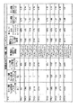
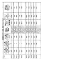
ゲイン係数βjの同じ計算は、受信WTRU30内の「信号伝達されたゲイン係数」と送信WTRU10内の「計算されたゲイン係数」の両方について決定する場合に使用するのが好ましい。しかし、3GPP CDMAシステムにおけるダウンリンク送信では、例えば、固定された値のセットのみを送信WTRU10に信号伝達することができる。したがって、そのような制限が発生する場合はUE「信号伝達されたゲイン係数」について、量子化されたゲイン係数、すなわち量子化されたβjは処理デバイス50によって決定され、送信WTRU10へ送信されるのが好ましい。3GPP CCTrCHでは、現在許可されている量子化されたβ値がTS 25.331に規定されている。これを表1に示す。
The same calculation of gain factor βj is preferably used when determining both “signaled gain factor” in receiving
1/8から2まで1/8刻みに16の量子化された値を使用できることに留意されたい。 Note that 16 quantized values from 1/8 to 2 in 1/8 steps can be used.
本発明の教示により、まず前述のβrefに比例する値としてβjを決定することによって、量子化されたβjが決定されるのが好ましい。したがって、j番目のTFCを使用する3GPP CCTrCHでは次のようになるのが好ましい。 In accordance with the teachings of the present invention, the quantized βj is preferably determined by first determining βj as a value proportional to βref described above. Therefore, 3GPP CCTrCH using the jth TFC is preferably as follows.
量子化されたβj(βj quantized)は、さらに次のように決定されるのが好ましい。 It is preferable that the quantized βj (βj quantized) is further determined as follows.
ただし、 However,
![]()
![]()
はxより大きいかxと等しい最小の整数を表す。これは、実際の計算値を上回るβの値を提供する保守的なアプローチである。 Represents the smallest integer greater than or equal to x. This is a conservative approach that provides a value of β that exceeds the actual calculated value.
これに代わる量子化されたβj(βj quantized)の好ましい決定方法の例には、次のような式がある。 An example of a preferable method for determining quantized βj (βj quantized) as an alternative is as follows.
または Or
または Or
または Or
ここで、 here,
![]()
![]()
はxより小さいかxと等しい最大の整数を表す。前述のすべての式において、1/8より小さいゲイン係数値を1/8に切り上げ、2より大きい値を2に切り下げるのが好ましい。パフォーマンスを向上するには、すべてのゲイン係数値は1/8より大きく2より小さいように、参照TFCすなわちTFCrefを選択するのが好ましい。 Represents the largest integer less than or equal to x. In all the above equations, it is preferable to round up gain factor values less than 1/8 to 1/8 and values greater than 2 to 2. To improve performance, it is preferable to select the reference TFC or TFCref so that all gain factor values are greater than 1/8 and less than 2.
本発明の別の態様として、再構成時に電力制御を維持する上で発生する問題について以下に説明する。前述のように、発明者はTFCの新しいパンクチャリング/繰り返し(puncturing/repetition)に基づいて再収束するための電力制御の必要性を認識している。パンクチャリング/繰り返しに関連する再構成の後で、同じ出力パワーレベルをもたらすのではない新しいゲイン係数が計算または選択された場合は、再収束が必要となる。 As another aspect of the present invention, problems that occur in maintaining power control during reconfiguration will be described below. As mentioned above, the inventor has recognized the need for power control to reconverge based on the new puncturing / repetition of TFC. If a new gain factor is calculated or selected that does not result in the same output power level after reconstruction associated with puncturing / iteration, reconvergence is required.
例えば、CCTrCHの総ビットレートがこのCCTrCHに割り当てられた物理チャネルの総チャネルビットレートと異なる場合は、従来どおりDTX(Discontinuous Transmission)が、専用物理チャネルおよび共有物理チャネル(PUSCH、PDSCH、UL DPCH、およびDL DPCH)にマップされた3GPP CCTrCHに適用される。レートマッチング(Rate matching)は、一部のみにデータが格納されている物理チャネル全体を、完全に満たすために使用される。レートマッチングと多重化の後で、物理チャネルに送信されるデータがまったく存在しない場合は、その物理チャネルが送信から破棄される。物理チャネルの一部のみが破棄された場合は、CCTrCHは部分的にDTX状態にある。送信するデータが存在しない場合は、CCTrCHがDTX状態にある。DTX状態では、特殊なバーストの利用が適用される。 For example, when the total bit rate of the CCTrCH is different from the total channel bit rate of the physical channel assigned to this CCTrCH, the DTX (Discontinuous Transmission) is conventionally used as a dedicated physical channel and a shared physical channel (PUSCH, PDSCH, UL DPCH, And 3GPP CCTrCH mapped to (DL DPCH). Rate matching is used to completely fill the entire physical channel where only a portion of the data is stored. After rate matching and multiplexing, if no data is transmitted on the physical channel, the physical channel is discarded from transmission. When only a part of the physical channel is discarded, the CCTrCH is partially in the DTX state. When there is no data to transmit, CCTrCH is in the DTX state. In the DTX state, special burst usage applies.
部分的なDTXにより、パンクチャリング/繰り返しは、割り当てられたリソース単位の総数、すなわち総データレートのみでなく、割り当てられた物理チャネルの拡散係数にも依存する。例えば、拡散係数(SF:spreading factor)が1である1つの物理チャネルがCCTrCH(すなわち、16のリソース単位)に割り当てられる場合、送信されるビットの数が小さくても、その物理チャネルが完全に満たされるまで繰り返される。代わりに、SFが2である2つの物理チャネルがCCTrCHに割り当てられる(16のリソース単位、チャネル当たり8)場合、送信されるビットすべてが1つのSF2物理チャネルに収まる場合は、第2の物理チャネルは破棄される。この場合は、繰り返しのパーセンテージが1つのSF1の場合よりも小さい。したがって、パンクチャリング/繰り返しの量は、使用するTFC(送信されるビット数)および物理チャネルの設定によって変わる。 With partial DTX, puncturing / repetition depends not only on the total number of allocated resource units, ie the total data rate, but also on the spreading factor of the allocated physical channel. For example, if one physical channel with a spreading factor (SF) of 1 is assigned to a CCTrCH (ie, 16 resource units), the physical channel is completely transmitted even if the number of transmitted bits is small. Repeat until satisfied. Instead, if two physical channels with an SF of 2 are assigned to the CCTrCH (16 resource units, 8 per channel), the second physical channel if all transmitted bits fit into one SF2 physical channel Is destroyed. In this case, the repetition percentage is smaller than in the case of one SF1. Therefore, the amount of puncturing / repetition varies depending on the TFC (number of transmitted bits) used and the setting of the physical channel.
最初に物理チャネルはCCTrCH用に設定されており、ゲイン係数はCCTrCHの送信フォーマットの組合せセット(TFCS:transport format combination set)内の各TFCに対して定義されている。物理チャネルが正常に確立されると、アップリンク外部電力制御アルゴリズムは指定されたSIRターゲットに収束する。このSIRターゲットは、そのチャネルに対して現在設定されているゲイン係数に基づいている(すなわち、その物理チャネル設定によって生成されたパンクチャリング/繰り返しの量に基づいている)。 Initially, a physical channel is set for CCTrCH, and a gain coefficient is defined for each TFC in a CCTrCH transmission format combination set (TFCS). When the physical channel is successfully established, the uplink external power control algorithm converges to the designated SIR target. This SIR target is based on the gain factor currently set for that channel (ie, based on the amount of puncturing / repetition generated by that physical channel setting).
物理チャネルの再構成手順の間に拡散係数が変化し、それによって各TFCのパンクチャリング/繰り返しが変化する可能性がある。「計算されたゲイン係数」が使用され、参照TFCおよび参照ゲイン係数(βref)が同じに維持される場合に、WTRUは古い参照TFCおよび参照ゲイン係数、並びに新しい物理チャネル設定に基づくすべてのTFCのゲイン係数値を再計算する。この結果、電力制御がすでに収束しているパンクチャリング/繰り返しと比較して、同じ出力を発生しないゲイン係数が得られる。 During the physical channel reconfiguration procedure, the spreading factor may change, thereby changing the puncturing / repetition of each TFC. If a “calculated gain factor” is used and the reference TFC and reference gain factor (βref) are kept the same, then the WTRU will use the old reference TFC and reference gain factor, as well as all TFCs based on the new physical channel settings. Recalculate the gain factor value. This results in a gain factor that does not produce the same output as compared to puncturing / repetition where power control has already converged.
「信号伝達されたゲイン係数」が使用されている場合に、RNCにはすべてのTFCに対して同じゲイン係数値を保存するかまたは新しいゲイン係数を送信するかの2つの選択肢がある。新しい設定の前と後の各TFCに対するパンクチャリング/繰り返しが同じでない場合に、ゲイン係数を同じに維持するには再収束するための電力制御が必要になる。したがって、新しいゲイン係数を送信するのが好ましい。 When the “signaled gain factor” is used, the RNC has two options: save the same gain factor value for all TFCs or send a new gain factor. If the puncturing / repetition for each TFC before and after the new setting is not the same, power control to reconverge is required to keep the gain factor the same. Therefore, it is preferable to send a new gain factor.
新しいゲイン係数を決定するには、前述のように参照ゲイン係数βrefに比例するように参照TFCに基づいて値を再計算するのが便利である。参照TFCおよび参照ゲイン係数(βref)が同じに維持される場合に、古い参照TFCおよび参照ゲイン係数および新しい物理チャネル設定に基づくすべてのTFCに対するゲイン係数値が再計算されるのが好ましい。なぜならば、変化は、前述のように拡散係数およびレートマッチングパラメータに基づくのが好ましいX因子において発生する可能性が高いからである。「計算されたゲイン係数」と同様に、この結果、電力制御がすでに収束しているパンクチャリング/繰り返しに関連する同じ出力を発生しないゲイン係数が得られる。したがって、参照TFCおよび参照ゲイン係数値の選択は、「計算されたゲイン係数」および「信号伝達されたゲイン係数」の両方において、非常に重要である。 To determine a new gain factor, it is convenient to recalculate the value based on the reference TFC so that it is proportional to the reference gain factor βref as described above. If the reference TFC and reference gain factor (βref) are kept the same, the gain factor values for all TFCs based on the old reference TFC and reference gain factor and the new physical channel settings are preferably recalculated. This is because changes are likely to occur in the factor X, which is preferably based on the spreading factor and rate matching parameters as described above. Similar to the “calculated gain factor”, this results in a gain factor that does not produce the same output associated with puncturing / repetition where power control has already converged. Therefore, the selection of the reference TFC and the reference gain factor value is very important in both “calculated gain factor” and “signaled gain factor”.
次の例は、再構成によってゲイン係数値(すなわち出力)とパンクチャリング/繰り返しのレベルとの関係を変更する方法を示している。例で示されたゲイン係数値は量子化されていないが、例は「計算されたゲイン係数」または「信号伝達されたゲイン係数」の両方に適用される。3GPP CCTrCHのアップリンク電力制御においては、信号伝達されたゲイン係数はWTRUに信号伝達される前にUTRANによって量子化されるのが好ましい。 The following example shows how to change the relationship between gain factor value (ie, output) and puncturing / repeat level by reconstruction. The gain factor values shown in the examples are not quantized, but the examples apply to both “calculated gain factors” or “signaled gain factors”. In 3GPP CCTrCH uplink power control, the signaled gain factor is preferably quantized by the UTRAN before being signaled to the WTRU.
簡単のために、この第1の例では、βrefが1に等しいと仮定されており、レートマッチング(RM:Rate Matching)属性はCCTrCHのすべての送信チャネルに対して同じ値になるように選択されると仮定される。しかし、βrefが1でない場合や送信チャネルのRM属性が等しくない場合も、同じ問題と解決策が適用される。 For simplicity, it is assumed in this first example that βref is equal to 1, and the rate matching (RM) attribute is selected to be the same value for all transmission channels of the CCTrCH. It is assumed. However, the same problems and solutions apply when βref is not 1 or when the RM attributes of the transmission channels are not equal.
説明のため、この例では、128Kbpsの無線アクセスベアラ(RAB:Radio Access Bearer)のアップリンク設定を選択する。ただし、RABは128Kbps専用トラフィックチャネル(DTCH)および3.4 Kbpsの信号伝達無線ベアラ(SRB:Signaling Radio Bearer)で構成される。このRABの設定は、表2および表3に示されており、このCCTrCHのTFCSは表4で定義される。 For the sake of explanation, in this example, the uplink setting of a radio access bearer (RAB) of 128 Kbps is selected. However, the RAB is composed of a 128 Kbps dedicated traffic channel (DTCH) and a 3.4 Kbps signaling radio bearer (SRB). The RAB settings are shown in Tables 2 and 3, and the TFCS of this CCTrCH is defined in Table 4.
CCTrCHの第1の例では、表5に示す2つの可能な物理チャネル設定について考察する。 In the first example of CCTrCH, consider the two possible physical channel configurations shown in Table 5.
物理チャネル設定1を使用するか2を使用するかは、チャネルが設定されたときのセルの可用性によって決まる。例えば、1つのSF2コードが使用できない場合は、代わりに2つのSF4コードを使用してもよい。 Whether to use physical channel setting 1 or 2 depends on the availability of the cell when the channel is set. For example, when one SF2 code cannot be used, two SF4 codes may be used instead.
この第1の例では、チャネルが初めて設定されたときは物理チャネル設定1が使用される。したがって、ゲイン係数は前述の好ましい式を使用して物理チャネル設定1に基づいて決定される。この例では、選択された参照TFCはTFC3なのでTFC3が選択されており、したがって、図4の表には各TFCに対するゲイン係数が示されている。 In this first example, physical channel setting 1 is used when a channel is set for the first time. Therefore, the gain factor is determined based on physical channel setting 1 using the preferred formula described above. In this example, since the selected reference TFC is TFC3, TFC3 is selected, so the table of FIG. 4 shows the gain factor for each TFC.
その後再構成が必要な場合は、新しいゲイン係数が計算される。例えば、物理設定2に再構成が行われ、参照TFCとゲイン係数が同じに維持される(すなわち、TFCrefがTFC3かつβref=1)場合は、再計算されたゲイン係数が図5の表に示されている。
If a reconstruction is then required, a new gain factor is calculated. For example, if
TFC3が参照として使用されている場合は、両方の設定についてパンクチャリング/繰り返しの関数としてのゲイン係数が図6のグラフに示されている。示されているゲイン係数の値は、量子化されていない。参照ゲイン係数の量子化は、「計算されたゲイン係数」の場合は必要ない。その場合、送信WTRU10によって決定されたゲイン係数の値は、図4および図5に示されている。量子化は、アップリンク3GPP CCTrCH用の「信号伝達されたゲイン係数」の場合に必要であり、この場合は送信された値はこの第1の例の図4および図5で示した値を量子化したものである。
If TFC3 is used as a reference, the gain factor as a function of puncturing / iteration for both settings is shown in the graph of FIG. The value of the gain factor shown is not quantized. Quantization of the reference gain coefficient is not necessary for the “calculated gain coefficient”. In that case, the value of the gain factor determined by the transmitting
この第1の例では、設定1ではTFC3が30%の繰り返しをもたらし、設定2ではTFC3が35%のパンクチャリングをもたらす。しかし、ゲイン係数の値はいずれの場合も同じである(すなわち1に等しい)。アップリンク外部ループ電力制御が物理チャネル設定1に与えられたベータの値について収束しており、SIRターゲット値が再構成中に更新されていない場合は、新しい収束が必要になる。この第1の例では、設定2の出力電力は非常に低くなる可能性が高く、SIRターゲットを増大させる必要がある。 In this first example, setting 1 results in 30% repetition of TFC3 and setting 2 results in puncturing 35% of TFC3. However, the value of the gain factor is the same in all cases (ie equal to 1). If the uplink outer loop power control has converged for the value of beta given to physical channel setting 1 and the SIR target value has not been updated during reconfiguration, a new convergence is required. In this first example, the output power of setting 2 is likely to be very low and the SIR target needs to be increased.
次のように、2つの解決策が提供される。 Two solutions are provided as follows.
1.参照TFCのインテリジェントな選択:SIRターゲットを維持(外部ループ電力制御アルゴリズムによって決定された最新の値を再構成メッセージにおいてWTRU10に送信)し、
a.CCTrCHの新しい設定において、同様のパンクチャリング/繰り返しに対して同様の出力レベルを提供するような元の選択肢が選択された場合は、既存の参照TFCおよびβrefを維持する。または
b.新しい参照TFCまたは新しいβrefを選択する。
1. Intelligent selection of reference TFC: maintain SIR target (send the latest value determined by outer loop power control algorithm to WTRU 10 in reconfiguration message)
a. In the new setting of CCTrCH, the existing reference TFC and βref are maintained if the original option is selected that provides a similar power level for similar puncturing / repetition. Or b. Select a new reference TFC or a new βref.
2.ゲイン係数値の変化に基づいてSIRターゲット値を更新し、そのSIRターゲット値を再構成メッセージにおいてWTRU10に送信する。この場合、βrefは同じに維持されるが、TFCS内の他のすべてのTFCのゲイン係数は変化してもよい。
2. Update the SIR target value based on the change in gain coefficient value and send the SIR target value to the
参照TFCのインテリジェントな選択では、SIRターゲットを維持し、参照TFCおよびβrefをインテリジェントに選択する。物理チャネルが再構成される場合は、次の3つのケースが考えられる
ケース1:CCTrCHの可能なすべての物理設定が既知であり、含まれるすべての物理チャネルの設定に対して同様のパンクチャリング/繰り返しをもたらす共通のTFCが存在する場合の参照TFCの選択。
ケース2:取り得るすべての設定が既知でない場合、または含まれるすべての物理チャネルの設定に対して同様のパンクチャリング/繰り返しをもたらす共通のTFCを検出できない場合の参照TFCの選択。および
ケース3:古い設定の参照TFCと同様のパンクチャリング/繰り返しをもたらすTFCを、新しい設定内で検出できない場合の参照TFCの選択。
The intelligent selection of the reference TFC maintains the SIR target and intelligently selects the reference TFC and βref. When physical channels are reconfigured, the following three cases are considered: Case 1: All possible physical configurations of CCTrCH are known and similar puncturing / configuration for all included physical channel configurations Selection of a reference TFC when there is a common TFC that causes repetition.
Case 2: Selection of a reference TFC when not all possible settings are known or when a common TFC cannot be detected that results in similar puncturing / repetition for all included physical channel settings. And Case 3: Selection of a reference TFC when a TFC that results in puncturing / repetition similar to the reference TFC in the old setting cannot be detected in the new setting.
第1のケースでは、参照TFCと参照ゲイン係数値を維持するのが好ましい。この場合は、このCCTrCHで許可されるすべての設定に対して同様の量のパンクチャリング/繰り返しをもたらす参照TFCが選択される。CCTrCHのすべての物理チャネル設定で同じ参照TFCと参照ゲイン係数が使用される。参照TFCと参照ゲイン係数はチャネルが最初に設定されるときに選択され、以降のすべての再構成でも同じに維持される。 In the first case, it is preferable to maintain the reference TFC and the reference gain coefficient value. In this case, a reference TFC is selected that results in a similar amount of puncturing / repetition for all settings allowed on this CCTrCH. The same reference TFC and reference gain factor are used in all physical channel settings of CCTrCH. The reference TFC and reference gain factor are selected when the channel is first set up and remain the same for all subsequent reconfigurations.
第2のケースでは、参照TFCを変更し、参照ゲイン係数値を維持するのが好ましい。この場合、古い設定における参照TFCと同様のパンクチャリング/繰り返しをもたらす新しい参照TFCが選択される。また、新しい参照TFCのゲイン係数βrefは再構成の間に同じに維持される。 In the second case, it is preferable to change the reference TFC and maintain the reference gain coefficient value. In this case, a new reference TFC is selected that results in puncturing / repetition similar to the reference TFC in the old setting. Also, the gain factor βref of the new reference TFC is kept the same during reconstruction.
第3のケースでは、参照TFCを維持し、参照ゲイン係数値を変更するのが好ましい。この場合、同じ参照TFCが使用されるが、参照ゲイン係数βrefは変更される。新しい参照ゲイン係数は、古い設定で使用されたものと同じ参照TFCを参照として使用して決定される。 In the third case, it is preferable to maintain the reference TFC and change the reference gain coefficient value. In this case, the same reference TFC is used, but the reference gain coefficient βref is changed. The new reference gain factor is determined using as a reference the same reference TFC that was used in the old setting.
上記すべてのケースについて、参照TFCおよび/または参照ゲイン係数値βrefが同じに維持される場合でも、TFCS内の他のすべてのTFCに対するゲイン係数値は、拡散係数の変化(すなわちLjの値の変化)がある限り、再計算されるのが好ましい。 For all the above cases, even if the reference TFC and / or the reference gain coefficient value βref are kept the same, the gain coefficient values for all other TFCs in the TFCS will change the spreading factor (ie change the value of Lj). ) Is preferably recalculated.
好ましくはないが、ケース2で定義した選択プロセスをケース1のシナリオで使用してもよい。またケース3で定義したプロセスをケース1またはケース2のシナリオで使用してもよい。
Although not preferred, the selection process defined in
インテリジェントな選択を使用するTFCS再構成の場合に、第1の好ましい選択肢(alterative)は、参照TFCを変更し、参照ゲイン係数値を維持することである。これは、古い設定の参照TFCと同様のパンクチャリング/繰り返しをもたらす新しい参照TFCを選択することによって行うのが好ましい。その場合、新しい参照TFCのゲイン係数は再構成の間は同じに維持されるのが好ましい。第2の好ましい選択肢は、参照ゲイン係数値を変更することである。新しい参照TFCは、TFCS内のどのTFCでもよい(古いものと同じでも異なるものでもよい)のが好ましい。新しい参照TFCのゲイン係数は、古い設定で使用されたβrefを参照として使用して決定するのが好ましい。 In the case of TFCS reconstruction using intelligent selection, the first preferred alternative is to change the reference TFC and maintain the reference gain factor value. This is preferably done by selecting a new reference TFC that results in puncturing / repetition similar to the old setting reference TFC. In that case, the gain factor of the new reference TFC is preferably kept the same during the reconstruction. A second preferred option is to change the reference gain factor value. The new reference TFC is preferably any TFC in the TFCS (which may be the same as or different from the old one). The gain factor of the new reference TFC is preferably determined using βref used in the old setting as a reference.
TFCS設定の場合、参照TFCおよび/または参照ゲイン係数値が同じに維持される場合でも、TFCS内における他のすべてのTFCのゲイン係数値は、指定された送信チャネルのビット数の変化(すなわちKjの値の変化)がある限り、再計算するのが好ましい。しかし、物理チャネルおよび/またはTFCS再構成の結果、再構成の前と後で同様のパンクチャリング/繰り返しをもたらす場合に、許容される代替策は参照TFCも参照ゲイン係数も更新しないことである。 For TFCS configuration, even if the reference TFC and / or reference gain factor values are kept the same, the gain factor values of all other TFCs in the TFCS are subject to changes in the number of bits of the specified transmission channel (ie Kj It is preferable to recalculate as long as there is a change in the value of. However, if the physical channel and / or TFCS reconfiguration results in similar puncturing / repetition before and after reconfiguration, the allowed alternative is not to update the reference TFC or reference gain factor.
前述のケース1で、取り得るすべての物理チャネル設定が既知の場合に、そのCCTrCHで許容されるすべての設定において同様の量のパンクチャリング/繰り返しをもたらすTFCがすべての設定に対する参照TFCとして選択されるのが好ましい。参照TFC(βref)に対するゲイン係数もすべての設定に対して同じであるのが好ましい。
In
「計算されたゲイン係数」の場合に、受信WTRU30はCCTrCHが最初に設定されたときに参照TFCと参照ゲイン係数(βref)を送信WTRU10に送信するのが好ましい。その場合、送信WTRU10は、前述の方法を使用して他のすべてのTFCに対するゲイン係数を計算するのが好ましい。物理チャネルの再構成に続き、送信WTRU 10は、事前に識別された参照TFCおよび参照ゲイン係数を使用して、TFCS内のすべてのTFCに対する新しいゲイン係数を計算する。
In the case of “calculated gain factor”, the receiving
「信号伝達されたゲイン係数」の場合に、受信WTRU30はCCTrCHが最初に設定されたときに選択された参照TFCを使用してTFCS内のすべてのTFCのゲイン係数を決定し、これらの値を送信WTRU10に送信するのが好ましい。3GPP CCTrCHでは、これらの値は量子化されるのが好ましい。受信WTRU30は、前述の方法を使用し、参照TFCに基づいて他のすべてのTFCのゲイン係数を決定するのが好ましい。物理チャネルの再構成が行われた場合は、受信WTRU 30は事前に識別された参照TFCと参照ゲイン係数を使用し、TFCS内のすべてのTFCの更新されたX値を使用して新しいゲイン係数を計算し、新しいゲイン係数を送信WTRU10に送信する。
In the case of “signaled gain factors”, the receiving
3GPP CCTrCHの場合に、参照ゲイン係数(βref)は1/8から2までの任意の値(1/8刻み)が望ましい。参照TFCおよびゲイン係数(βref)は、他のTFCのすべてのゲイン係数値が1/8より大きく、2より小さくなるように選択するのが好ましい。また、物理チャネル再構成によって拡散係数が変化しない場合は、ゲイン係数を変更する必要はない。 In the case of 3GPP CCTrCH, the reference gain coefficient (βref) is desirably an arbitrary value (1/8 step) from 1/8 to 2. The reference TFC and gain factor (βref) are preferably selected so that all gain factor values of other TFCs are greater than 1/8 and less than 2. Further, when the spreading factor does not change due to physical channel reconfiguration, it is not necessary to change the gain factor.
前述の第1の例で、参照TFCであるTFC3は、物理設定1で30%の繰り返しをもたらし、物理設定2で35%のパンクチャリングをもたらす。しかし、TFC4は物理設定1で3%のパンクチャリングをもたらし、物理設定2で1%の繰り返しをもたらす。TFC4の値はTFC3より互いにはるかに近いので、ケース1のシナリオではTFC4を参照TFCとして選択するのが好ましい。
In the first example described above, the reference TFC TFC3 results in 30% repetition at
ケース1のシナリオでは、第1の例を修正したものが第2の例として図7、図9および図10とともに提供されている。第2の例の参照としてTFC4を使用したときのゲイン係数は、設定1と設定2の両方によるパンクチャリング/繰り返しの関数として図7のグラフに示されている。図7のグラフを図6に示されているグラフと比較すると、2つの曲線がはるかに接近していることがわかる。
In the
また、ケース1のシナリオでは、TFC10を参照として選択した場合に、第1の例を修正したものが第3の例として図8、図9および図10とともに提供されている。TFC10は、物理設定1において46%のパンクチャリングをもたらし、物理設定2において45%のパンクチャリングをもたらす。第3の例の参照としてTFC10を使用した場合は、両方の設定によるパンクチャリング/繰り返しの関数としてのゲイン係数が図8に示されている。この図は、この場合も同様に適切な結果が得られることを示している。
Further, in the scenario of
参照としてTFC4またはTFC10のいずれを使用した場合でも、物理設定2によるパンクチャリング/繰り返しの関数としてのゲイン係数を示す曲線は物理設定1によるものと重なる。指定されたパンクチャリング/繰り返しに対するゲイン係数値は両方の設定でほぼ同じである。図示されているゲイン係数の値は、量子化されていない。
Regardless of whether TFC4 or TFC10 is used as a reference, the curve indicating the gain coefficient as a function of puncturing / repetition with
図9および図10の表は、それぞれ第2と第3の例の両方に対して、2つの物理設定に関する詳細な結果を示している。 The tables of FIGS. 9 and 10 show the detailed results for the two physical settings for both the second and third examples, respectively.
第1の例については、第2と第3の例を簡単にするために、βrefは1に等しくなるように選択し、レートマッチング(RM)属性はCCTrCHのすべての送信チャネルで同じ値を選択することが想定されている。βrefが1でない場合や送信チャネルのRM属性が等しくない場合にも、同じ問題と解決策が適用される。 For the first example, to simplify the second and third examples, βref is chosen to be equal to 1, and the rate matching (RM) attribute is chosen to be the same for all transmission channels of CCTrCH. It is assumed that The same problem and solution apply even when βref is not 1 or the RM attributes of the transmission channels are not equal.
前述のケース1の解決策は、CCTrCHに割り当てられているすべての可能な物理設定が既知の場合にのみ好ましい。この解決策は、関連する物理設定が2つのみの場合は単純である。3つ以上の関連する設定が存在する場合は、関連するすべての物理チャネル設定に対してパンクチャリング/繰り返しで同様の結果をもたらす共通のTFCを見つけるのは困難となることがある。
The
ケース2において、設定が事前に知られていない場合、または関連するすべての物理チャネル設定に対して同様のパンクチャリング/繰り返しをもたらす共通のTFCを検出することが不可能な場合は、再構成の間に新しい参照TFCを選択するのが好ましい。新しい参照TFCは、古い設定における参照TFCと同様のパンクチャリング/繰り返しをもたらすものを選択するのが好ましい。新しい参照TFC(βref)のゲイン係数は、再構成の間は変更しないのが好ましい。
In
「計算されたゲイン係数」の場合は、受信WTRU30は新しい参照TFCと(変更されていない)参照ゲイン係数(βref)を、再構成メッセージにおいて送信WTRU10に送信するのが好ましい。参照ゲイン係数を変更しない場合でも、再構成メッセージにおいて送信するのが好ましい。3GPPでは、参照TFCを送信する場合にゲイン係数値を送信する必要がある。ここで、送信WTRU10は他のすべてのTFCのゲイン係数を計算する。
For “calculated gain factors”, the receiving
「信号伝達されたゲイン係数」の場合に、受信WTRU 30は新しく選択された参照TFCと(変更されていない)参照ゲイン係数(βref)を使用してTFCS内のすべてのTFCのゲイン係数を決定し、これらの値を3GPPのコンテクスト内で量子化して送信WTRU10に送信するのが好ましい。いずれの場合でも、ゲイン係数は前述の好ましい式を使用して計算するのが好ましい。
In the case of “signaled gain factor”, the receiving
ケース2のシナリオにおいて、TFC3が初期設定(設定1)の参照として選択されている場合は、約30%の繰り返しをもたらす設定2の参照TFCをTFCとして選択するのが好ましい。ケース2の第1の例の修正に基づく第4の例を、図4、図11、および図12とともに説明する。TFC3に最も近い値はTFC6であり、56%の繰り返しをもたらす。このTFCのゲイン係数は、物理設定1におけるTFC3のゲイン係数と同じである(指定された例においてゲイン係数は1に等しい)。
In
図11は、第4の例として、TFC3が物理チャネル設定1で参照として使用された場合、およびTFC6が物理チャネル設定2で参照として使用された場合の両方の設定によるパンクチャリング/繰り返しの関数としてゲイン係数を示している。図示されたゲイン係数の値は、量子化されていない。設定1と2の繰り返しの間には相対的に大きな差があるため(26%の差)、2つの曲線は図7および図8に描かれているケース1の例ほどに接近してはいないが、第1の例を反映する図6のグラフに示された結果よりはかなり良い。
FIG. 11 shows, as a fourth example, as a function of puncturing / repetition with both settings when TFC3 is used as a reference in physical channel setting 1 and when TFC6 is used as a reference in physical channel setting 2 The gain coefficient is shown. The gain coefficient values shown are not quantized. Because there is a relatively large difference between the iterations of
図12の表は、第4の例の参照TFCがTFC6の場合に、物理設定2に対する詳細な結果を示している。第4の例は第1の例の続きであり、第1の例では、簡単にするために、βrefは1に等しくなるように選択され、Rate Matching属性はCCTrCHのすべての送信チャネルで同じ値になるように選択されることが仮定されている。βrefが1ではなく、送信チャネルのRM属性が等しくない場合にも、ケース2と同じ問題と解決策が適用される。
The table of FIG. 12 shows detailed results for the
ケース3において、古い設定の参照TFCと同様のパンクチャリング/繰り返しをもたらすTFCを新しい設定で検出できない場合は、再構成の間に新しい参照TFCを選択するのが好ましい。新しい参照TFCは、現在の参照TFCも含めてTFCS内のどのTFCでもよい。新しい参照TFCのゲイン係数(βref,new)は、次のように古い設定において使用されていたものと同じ参照を参照として使用し、決定するのが好ましい。
In
すなわち、古い設定(古い拡散係数)と古いβrefを参照として使用して新しいβrefを決定する。 That is, a new βref is determined using the old setting (old diffusion coefficient) and the old βref as a reference.
新しい参照TFCが古い参照TFCと同じになるように選択された場合は、Kref,new=Kref,oldであり、したがって、好ましい計算は次のようになる。 If the new reference TFC is chosen to be the same as the old reference TFC, then Kref, new = Kref, old, so the preferred calculation is:
この新しい参照ゲイン係数は、新しい設定における他のすべてのTFCのゲイン係数を決定するための参照として使用される。したがって、好ましくは前述の好ましい式を使用してj番目のTFCのゲイン係数βjを計算するためのβrefとして、βref,newを使用する。 This new reference gain factor is used as a reference to determine the gain factor of all other TFCs in the new setting. Therefore, preferably, βref, new is used as βref for calculating the gain coefficient βj of the j-th TFC using the above-mentioned preferable formula.
ケース3のシナリオでは、第1の例にさらに修正を加えたものが図4、図13、および図14とともに第5の例として提供されている。第5の例では、TFC3、すなわち第1の例の古い参照TFCと同じものが新しい参照TFCとして選択されている。次のように、物理設定1は古い設定として、物理設定2は新しい設定として、さらにTFC3は古い参照TFCおよび新しい参照TFCとして使用される。
In the
Lref,old=1/2(物理設定=SF2×1コード×1タイムスロット)
Lref,new=1/4(物理設定=SF4×1コード×1タイムスロット)
βref,old=1
したがって、
Lref, old = 1/2 (physical setting = SF2 × 1 code × 1 time slot)
Lref, new = 1/4 (physical setting = SF4 × 1 code × 1 time slot)
βref, old = 1
Therefore,
図13は、TFC3が物理設定1および物理設定2において参照として使用され、新しい参照ゲイン係数がこの第5の例に対して決定された場合について、このケースにおける両方の設定によるパンクチャリング/繰り返しの関数としてゲイン係数を示している。図13のグラフを図6に示されているものと比較すると、2つの曲線がより接近していることがわかる。これは指定されたパンクチャリング/繰り返しによるゲイン係数値が、両方のケースでほぼ同じであることを示している。図13では、物理設定2の曲線は物理設定1の曲線と実際に重なっている(すなわち、指定されたパンクチャリング/繰り返しによるゲイン係数値は両方の設定でほぼ同じである)。
FIG. 13 shows the puncturing / repetition with both settings in this case for the case where TFC3 is used as a reference in
図14の表では、新しい参照TFCがTFC3のままであり、新しい参照ゲイン係数が第5の例における古い参照ゲイン係数から決定された場合の物理設定2に対する詳細な結果を示している。
The table of FIG. 14 shows detailed results for
ゲイン係数値は量子化されていない。3GPP CCTrCHでは、参照ゲイン係数が1に等しくないかまたは1/8の倍数でないので、送信WTRU10に値を送信するには量子化が必要である。したがって、「計算されたゲイン係数」のケースで送信WTRU10によって決定された他のすべてのTFCのゲイン係数値はこの第5の例に示されている値とはわずかに異なる。「信号伝達されたゲイン係数」のケースでは、送信されたすべてのゲイン係数値は、3GPP CCTrCHのこの第5の例で示された量子化されたバージョンの値であるのが好ましい。
The gain coefficient value is not quantized. In 3GPP CCTrCH, the reference gain factor is not equal to 1 or not a multiple of 1/8, so quantization is required to transmit a value to the transmitting
「計算されたゲイン係数」のケースでは、量子化誤差を最小にするために、受信WTRU 30は量子化された値が量子化したゲイン係数値に最も近くなるような新しい参照ゲイン係数をもたらす参照TFCを新しい参照TFCとして選択するのが好ましい。
In the “calculated gain factor” case, in order to minimize the quantization error, the receiving
前述の3つのケースでは、TFCS再構成中にTFCS内で変更されるパラメータはゲイン係数のみと仮定されている。送信フォーマットを再構成する必要があるので、データ転送速度に影響を与えるケースも存在する。このようなケースでは、新しい参照TFCをインテリジェントに選択することも望ましい。選択は、前述のケースに関連して示された解決策を使用して行われるのが好ましい。 In the three cases described above, it is assumed that the only parameter that is changed in the TFCS during TFCS reconfiguration is the gain factor. Since the transmission format needs to be reconfigured, there are cases where the data transfer rate is affected. In such cases, it is also desirable to intelligently select a new reference TFC. The selection is preferably made using the solution presented in connection with the previous case.
換言すると、TFCS再構成の間には好ましい選択が2つある。1つの好ましい選択肢は、古い設定における参照TFCと同様のパンクチャリング/繰り返しをもつ新しい参照TFCを選択することである。新しい参照TFCのゲイン係数(βref)は再構成の間は同じに維持する必要がある。これは第2、第3、および第4の例で説明したケース1または2と同様である。
In other words, there are two preferred choices between TFCS reconfigurations. One preferred option is to select a new reference TFC with similar puncturing / repeat as the reference TFC in the old setting. The gain factor (βref) of the new reference TFC needs to be kept the same during the reconstruction. This is the same as
もう1つの好ましい選択肢は、古い参照TFCを含むTFCS内の任意のTFCを新しい参照TFCとして選択することである。新しい参照TFCのゲイン係数(βref,new)は、次のように古い設定で使用されていたものと同じ参照を参照として使用して決定する必要がある。 Another preferred option is to select any TFC in the TFCS that contains the old reference TFC as the new reference TFC. The gain factor (βref, new) of the new reference TFC needs to be determined using the same reference as the reference that was used in the old setting as follows:
すなわち、古い設定(古い拡散係数)と古いβrefを参照として使用して新しいβrefを決定する。新しい参照TFCが、古い参照TFCと同じになるように選択された場合は、Kref,new=Kref,oldであり、計算は次のように簡素化される。 That is, a new βref is determined using the old setting (old diffusion coefficient) and the old βref as a reference. If the new reference TFC is selected to be the same as the old reference TFC, then Kref, new = Kref, old, and the calculation is simplified as follows.
その場合、新しい参照ゲイン係数は、新しい設定における他のすべてのTFCのゲイン係数を決定するための参照として使用される。これは第5の例で示されているケース3と同様である。
In that case, the new reference gain factor is used as a reference to determine the gain factors of all other TFCs in the new setting. This is the same as
インテリジェントな選択の代替策として、物理チャネルの再構成の間にゲイン係数の変更に基づいてSIRターゲットを更新できる。インテリジェントな選択に関する上の議論において、SIRターゲットは再構成の間に変化しない、すなわちUL外部ループ電力制御アルゴリズムからの最新の更新が再構成メッセージとして送信WTRU 10に送信される。以下で説明する代替の解決策は、物理チャネル再構成の間にSIRターゲットの更新を伴う。
As an alternative to intelligent selection, the SIR target can be updated based on gain factor changes during physical channel reconfiguration. In the above discussion on intelligent selection, the SIR target does not change during reconfiguration, ie the latest update from the UL outer loop power control algorithm is sent to the sending
このケースでは、参照TFCおよび参照ゲイン係数は物理チャネル再構成の間は同じに維持される。SIRターゲットは、電力制御を維持するために参照ゲイン係数値の中で予期された変更に基づいて再計算される。 In this case, the reference TFC and reference gain factor remain the same during physical channel reconfiguration. The SIR target is recalculated based on the expected change in the reference gain factor value to maintain power control.
SIRターゲットは、次のようにして更新されるのが好ましい。調整係数(adjustment factor)βadjは、参照TFCのゲイン係数βrefと電力制御を維持するために選択された新しい物理チャネル設定に基づいて次のように決定されるのが好ましい。 The SIR target is preferably updated as follows. The adjustment factor βadj is preferably determined as follows based on the gain factor βref of the reference TFC and the new physical channel setting selected to maintain power control.
ここで、 here,
![]()
![]()
ここで、SFiは第1の物理設定に関する専用物理チャネル(DPCH)iの拡散係数であり、TFCrefで使用するすべてのDPCHiについて合計を求める。さらに、 Here, SFi is a spreading coefficient of the dedicated physical channel (DPCH) i related to the first physical setting, and the sum is obtained for all DPCHi used in TFCref. further,
![]()
![]()
ここで、SFiは第2の物理設定に関する専用物理チャネル(DPCH)iの拡散係数であり、TFCrefで使用するすべてのDPCHiについて合計を求める。 Here, SFi is a spreading coefficient of the dedicated physical channel (DPCH) i related to the second physical setting, and the sum is obtained for all DPCHi used in TFCref.
その場合、新しいSIRターゲットは、次のようにして得られる。 In that case, a new SIR target is obtained as follows.
古い設定の参照TFCのゲイン係数が1に設定された場合に、新しいSIRターゲットは次のように簡素化された式で与えられる。 When the old setting reference TFC gain factor is set to 1, the new SIR target is given by the following simplified formula:
S1R_targetnew=S1R_targetold+20log(βadj)
その場合、更新されたSIRターゲットは、再構成メッセージにおいて送信WTRU10に送信される。参照TFCおよび参照ゲイン係数(βref)は同じに維持される、すなわち調整係数βadjは更新されたSIRターゲットを決定するためにのみ使用されるが、その後でゲイン係数として使用されることはない。
S1R_target new = S1R_target old +20 log (β adj )
In that case, the updated SIR target is sent to the sending
「計算されたゲイン係数」の場合に、再構成メッセージの参照TFCおよびβrefは同じに維持されるので、再送信する必要はない。送信WTRU10は、古い参照TFCと古い参照ゲイン係数に基づいて、他のすべてのTFCのゲイン係数値を計算する。送信WTRU10は、古い参照ゲイン係数を使用して説明した前述の好ましい式を使用するのが好ましい。
In the case of “calculated gain factor”, the reconfiguration message reference TFC and βref are kept the same, so there is no need to retransmit. The transmitting
「信号伝達されたゲイン係数」の場合は、物理チャネル再構成の間に、受信WTRU 30は参照TFCとβrefを使用してTFCS内のすべてのTFCに対するゲイン係数を決定し、これらの値を好ましくは3GPP CCTrCHのコンテクスト用に量子化して送信WTRU10に送信する。その他すべてのTFCのゲイン係数値は、物理チャネル設定の変化に従って変更できる。受信WTRU30は、古い参照ゲイン係数を使用して説明した前述の好ましい式を使用するのが好ましい。
In the case of “signaled gain factors”, during physical channel reconfiguration, the receiving
「計算されたゲイン係数」の場合、前述のインテリジェントな選択方法と比較すると、SIRターゲットの更新には、信号伝達のオーバヘッドを最小化するという利点がある。ゲイン係数は送信チャネル設定の一部なので、これらのパラメータにおける変更を送信WTRU10に通知するためには、このような変更が物理チャネル設定のみの変更に起因するものであっても、「送信チャネルの再構成(Transport Channel Reconfiguration)」メッセージを使用する必要がある。送信チャネル設定に変更はない場合、代わりに「物理チャネルの再構成(Physical Channel Reconfiguration)」メッセージが使用できる。このメッセージは、「送信チャネルの再構成(Transport Channel Reconfiguration)」メッセージよりも短いので好ましい。「計算されたゲイン係数」の場合は、SIRターゲットの更新が使用されていれば、参照TFCまたは参照ゲイン係数は変更する必要がない。すなわち送信チャネルの設定は変更されない。この場合、「物理チャネルの再構成」メッセージは再構成の送信WTRU10への通知に使用でき、信号伝達のオーバヘッドを最小化できる。
In the case of a “calculated gain factor”, the SIR target update has the advantage of minimizing signaling overhead compared to the intelligent selection method described above. Because the gain factor is part of the transmission channel settings, in order to notify the
送信WTRU10か受信WTRU30のいずれかのゲイン係数および量子化されたゲイン係数を決定するコンポーネントは、特定用途向け集積回路(ASIC)などの一つの集積回路に実装されるのが好ましい。しかし、このコンポーネントは、複数の別々の集積回路や汎用CPU/DSP上のソフトウェアで容易に実装することもできる。
The components that determine the gain factor and the quantized gain factor of either the transmitting
本発明について、好ましい実施形態を参照して詳細に示し、説明してきたが、本明細書で以上に説明した本発明の範囲を逸脱することなく、その形態および細部の様々な変更が可能なことは、当業者には言うまでもない。 Although the present invention has been shown and described in detail with reference to preferred embodiments, various changes in form and detail can be made without departing from the scope of the invention as described herein above. It goes without saying to those skilled in the art.
Claims (55)
参照となるチャネルの組合せに対して参照ゲイン係数βrefを決定するステップと、
前記フォワードコンポジットチャネル上でデータを送信するためのチャネルの組合せを選択するステップと、
前記選択されたチャネルの組合せが前記参照となるチャネルの組合せと同じでない場合は、前記選択されたチャネルの組合せに対するゲイン係数βが前記参照ゲイン係数βrefに比例するように、前記選択されたチャネルの組合せに関するゲイン係数βを計算するステップと、
前記選択されたチャネルの組合せを使用して、前記フォワードコンポジットチャネル上でデータ信号を送信する場合において、前記フォワードチャネルの電力調整を行うときに、前記選択されたチャネルの組合せに対する前記ゲイン係数βを前記フォワードコンポジットチャネルに適用するステップと、
を備えることを特徴とする方法。 A method for controlling transmit power of a wireless transmit / receive unit (WTRU) that transmits a signal over a forward composite channel carrying data in a selected channel combination, the WTRU receiving via the forward channel Configured to power adjust the forward channel as a function of a target metric calculated based on a data signal;
Determining a reference gain coefficient βref for a reference channel combination;
Selecting a combination of channels for transmitting data on the forward composite channel;
If the selected channel combination is not the same as the reference channel combination, the selected channel combination is such that a gain factor β for the selected channel combination is proportional to the reference gain factor βref. Calculating a gain factor β for the combination;
In the case where a data signal is transmitted on the forward composite channel using the selected channel combination, the gain coefficient β for the selected channel combination is set when performing power adjustment of the forward channel. Applying to the forward composite channel;
A method comprising the steps of:
ここで、
ことを特徴とする請求項2に記載の方法。 The gain coefficient βj is
here,
The method according to claim 2.
となるように決定されることを特徴とする請求項9に記載の方法。 The TFCref is selected so that all gain coefficient values are larger than 1/8 and smaller than 2, and the quantized gain coefficient βj (βj, quantized) is:
The method of claim 9, wherein the method is determined to be
前記フォワードチャネルを介して受信した前記通信データ信号に基づいて計算されたターゲットメトリックスデータを受信するように構成された受信機と、
受信したターゲットメトリックスデータの関数としてフォワードチャネルの電力調整を行うように構成された前記送信機に関連付けられて動作できるプロセッサであって、
前記プロセッサは、前記フォワードコンポジットチャネルを経由してデータを送信するために選択されたチャネルの組合せに対する送信機の電力制御のためにゲイン係数βを適用し、前記選択されたチャネルの組合せが参照となるチャネルの組合せと同じでない場合は、前記選択されたチャネルの組合せに対する前記ゲイン係数βを、前記選択されたチャネルの組合せに対するゲイン係数βが前記参照となるチャネルの組合せに対して決定された参照ゲイン係数βrefに比例させるように計算するよう構成されることと、
を備えることを特徴とする無線送受信ユニット(WTRU)。 A transmitter configured to transmit a signal over a forward composite channel carrying communication data in a selected channel combination;
A receiver configured to receive target metrics data calculated based on the communication data signal received via the forward channel;
A processor operable to be associated with the transmitter configured to perform forward channel power adjustment as a function of received target metric data;
The processor applies a gain factor β for transmitter power control to a combination of channels selected to transmit data via the forward composite channel, and the selected channel combination is referred to If the channel combination is not the same, the gain coefficient β for the selected channel combination is the reference for which the gain coefficient β for the selected channel combination is determined for the reference channel combination. Configured to calculate to be proportional to the gain factor βref;
A wireless transceiver unit (WTRU) comprising:
ことを特徴とする請求項12に記載のWTRU。 The processor sets the gain coefficient βj to
The WTRU of claim 12.
前記フォワードコンポジットチャネル上の選択されたチャネルの組合せにおいて、前記送信ユニットから送信された通信信号を受信するように構成された受信機と、
前記フォワードコンポジットチャネルを経由して受信した前記選択されたチャネルの組合せに対するゲイン係数βを計算し、前記ゲイン係数βは前記選択されたチャネルの組合せが参照となるチャネルの組合せである場合は、参照ゲイン係数βrefとなるように決定され、それ以外の場合は前記参照ゲイン係数βrefに比例するように計算されるよう構成されたプロセッサと、
前記ゲイン係数βを反映するデータを前記送信ユニットに送信し、前記送信ユニットはそれに基づいてフォワードチャネルの電力調整を行うことができるよう構成された送信機と、
を備えることを特徴とするWTRU。 A wireless transceiver unit (WTRU) configured to support transmission power control of a transmission unit that transmits a signal via a forward composite channel carrying communication data in a selected combination of channels, the transmission unit Is configured to perform forward channel power adjustment as a function of the gain factor determined by the WTRU;
A receiver configured to receive a communication signal transmitted from the transmission unit in a selected channel combination on the forward composite channel;
Calculate a gain factor β for the selected channel combination received via the forward composite channel, and the gain factor β is a reference channel combination when the selected channel combination is a reference channel A processor that is determined to be a gain factor βref, and is otherwise calculated to be proportional to the reference gain factor βref;
A transmitter configured to transmit data reflecting the gain factor β to the transmission unit, the transmission unit configured to perform forward channel power adjustment based thereon;
A WTRU comprising:
前記プロセッサは前記選択されたチャネルの組合せに対するゲイン係数を計算するように構成されており、j番目のチャネルの組合せTFCjは前記フォワードコンポジットチャネル上においてデータを送信するために前記送信ユニットが使用する前記選択されたチャネルの組合せであって、ただしTFCjがTFCrefでない場合には、前記選択されたチャネルの組合せのゲイン係数βjがβj=X×βrefとなるように計算されることを特徴とする請求項14に記載のWTRU。 The data channel is a transmission channel (TrCH), the composite channel is an uplink code composite transmission channel (CCTrCH), and is configured for use in a code division multiple access (CDMA) system. A combination (TFC) is associated with each of the CCTrCH predefined format channel combination sets, one of the format channel combinations being a reference channel combination TFCref;
The processor is configured to calculate a gain factor for the selected channel combination, and a j th channel combination TFCj is used by the transmitting unit to transmit data on the forward composite channel. If the channel combination is selected and TFCj is not TFCref, the gain coefficient βj of the selected channel combination is calculated such that β j = X × β ref 15. The WTRU of claim 14.
ことを特徴とする請求項16に記載のWTRU。 The processor sets the gain coefficient βj to
The WTRU of claim 16.
ことを特徴とする請求項21に記載のWTRU。 TFCref is selected such that all gain factor values are greater than 1/8 and less than 2, and the processor determines that the quantized gain factor βj (βj, quantized) is
24. The WTRU of claim 21.
前記フォワードコンポジットチャネルの第1の物理送信設定に対して選択されたチャネルの組合せで前記フォワードコンポジットチャネル内の通信信号を送信するステップと、
前記フォワードコンポジットチャネルの前記第1の物理送信設定に対して参照となるチャネルの組合せを決定するステップと、
ゲイン係数βを、前記フォワードコンポジットチャネルの前記第1の物理送信設定に対して前記選択されたチャネルの組合せによる通信信号の送信に適用するステップであって、前記ゲイン係数βは前記フォワードコンポジットチャネルの前記第1の物理送信設定に対する前記選択されたチャネルの組合せおよび前記参照となるチャネルの組合せの拡散係数に基づいて決定されることと、
前記フォワードコンポジットチャネルの第2の物理送信設定に対する選択されたチャネルの組合せにおいて前記信号を送信するために、前記フォワードコンポジットチャネル内の通信信号の送信を再構成するステップと、
前記フォワードコンポジットチャネルの前記第2の物理送信設定に対して参照となるチャネルの組合せを決定するステップと、
ゲイン係数β’を、前記フォワードコンポジットチャネルの前記第2の物理送信設定に対する前記選択されたチャネルの組合せによる通信信号の前記送信に適用するステップであって、前記ゲイン係数β’は、前記フォワードコンポジットチャネルの前記第2の物理送信設定に対する前記選択されたチャネルの組合せおよび前記参照となるチャネルの組合せの拡散係数に基づいて決定されることと、
を備えることを特徴とする方法。 Method for controlling transmission power of a wireless transceiver unit (WTRU) that transmits a communication signal via the forward composite channel that carries data in a combination of channels selected for a selected physical transmission setting of the forward composite channel Because
Transmitting a communication signal in the forward composite channel in a combination of channels selected for a first physical transmission setting of the forward composite channel;
Determining a reference channel combination for the first physical transmission setting of the forward composite channel;
Applying a gain factor β to transmission of a communication signal by the selected combination of channels for the first physical transmission setting of the forward composite channel, wherein the gain factor β is a value of the forward composite channel Being determined based on a spreading factor of the selected channel combination and the reference channel combination for the first physical transmission configuration;
Reconfiguring transmission of communication signals in the forward composite channel to transmit the signal in a selected channel combination for a second physical transmission setting of the forward composite channel;
Determining a reference channel combination for the second physical transmission setting of the forward composite channel;
Applying a gain factor β ′ to the transmission of the communication signal by the selected channel combination for the second physical transmission setting of the forward composite channel, the gain factor β ′ being the forward composite channel Being determined based on a spreading factor of the selected channel combination and the reference channel combination for the second physical transmission setting of a channel;
A method comprising the steps of:
前記方法においては、前記フォワードコンポジットチャネルの前記第1の物理送信設定に対する前記参照となるチャネルの組合せは、関連付けられたゲイン係数βref1を有するあらかじめ定義された一連のフォーマットチャネルの組合せの1つであるTFCref1に決定され、前記フォワードコンポジットチャネルの前記第2の物理送信設定に対する前記参照となるチャネルの組合せは、関連付けられたゲイン係数βref2を有するあらかじめ定義された一連のフォーマットチャネルの組合せの1つであるTFCref2に決定されることを特徴とする請求項24に記載の方法。 The WTRU is configured for use in a code division multiple access (CDMA) system, and the data channel is a transmission channel (TrCH) that can take various spreading factors corresponding to various physical settings of the composite channel. Yes, the composite channel is an uplink code composite transmission channel (CCTrCH), and a transmission format combination (TFC) is a series of predefined formats of the CCTrCH defined for all physical settings of the forward composite channel Associated with each channel combination,
In the method, the reference channel combination for the first physical transmission setting of the forward composite channel is one of a predefined series of format channel combinations having an associated gain factor βref1. The reference channel combination determined for TFCref1 and for the second physical transmission setting of the forward composite channel is one of a predefined set of format channel combinations with an associated gain factor βref2. 25. The method of claim 24, wherein the method is determined to be TFCref2.
ことを特徴とする請求項28に記載の方法。 The gain coefficient βref2 is
29. The method of claim 28, wherein:
ことを特徴とする請求項25に記載の方法。 The reference channel combination TFCref2 is selected to be a TFC different from the reference channel combination TFCref1, and the gain coefficient βref2 is
26. The method of claim 25.
前記フォワードコンポジットチャネルの前記第2の物理送信設定に対してデータを送信するためにk番目のチャネルの組合せTFCkが選択され、前記選択されたチャネルの組合せに対してβk=X’*βref2となるように計算されたゲイン係数βkが適用され、ここでX’は前記フォワードコンポジットチャネルの前記第2の物理送信設定に対してTFCkおよびTFCref2の拡散係数に基づいていることを特徴とする請求項25に記載の方法。 A j-th channel combination TFCj is selected to transmit data for the first physical transmission setting of the forward composite channel such that βj = X * βref1 for the selected channel combination. Is applied, where X is based on the spreading factor of TFCj and TFCref1 for the first physical transmission setting of the forward composite channel;
A k-th channel combination TFCk is selected to transmit data for the second physical transmission setting of the forward composite channel, and βk = X ′ * βref2 for the selected channel combination. 26. The gain factor βk calculated as follows is applied, wherein X ′ is based on the spreading factor of TFCk and TFCref2 for the second physical transmission setting of the forward composite channel: The method described in 1.
ことを特徴とする請求項34に記載の方法。 The gain coefficient βref2 is
35. The method of claim 34.
ことを特徴とする請求項31に記載の方法。 The reference channel combination TFCref2 is selected to be a TFC different from the reference channel combination TFCref1, and the gain coefficient βref2 is
32. The method of claim 31, wherein:
前記ゲイン係数βkは、
ことを特徴とする請求項31に記載の方法。 The gain coefficient βj is
The gain coefficient βk is
32. The method of claim 31, wherein:
前記フォワードチャネルを経由して受信したデータ信号に基づいて計算されたターゲットメトリックスの関数として前記フォワードチャネルの電力調整を行うとともに、前記フォワードコンポジットチャネルの前記選択された物理送信設定に対して参照となるチャネルの組合せに基づくゲイン係数を適用するように構成されたプロセッサとを備え、
前記送信機は、前記フォワードコンポジットチャネル内の通信信号の送信を、前記フォワードコンポジットチャネルの第1の物理送信設定に対する第1の選択されたチャネルの組合せによる送信から、前記フォワードコンポジットチャネルの第2の物理送信設定に対する第2の選択されたチャネルの組合せによる送信へ、再構成するように構成さていれることと、
前記プロセッサは、ゲイン係数βを、前記ゲイン係数βが前記フォワードコンポジットチャネルの前記第1の物理送信設定に対する前記第1の選択されたチャネルの組合せおよび参照となるチャネルの組合せの拡散係数に基づいて決定されるように計算し、前記フォワードコンポジットチャネルの前記第1の物理送信設定に対する前記第1の選択されたチャネルの組合せによる通信信号の送信に適用するように構成されることと、
前記プロセッサは、ゲイン係数βを、前記ゲイン係数βが前記フォワードコンポジットチャネルの前記第2の物理送信構成に対する前記第2の選択されたチャネルの組合せおよび参照となるチャネルの組合せの拡散係数に基づいて決定されるように計算し、前記フォワードコンポジットチャネルの前記第2の物理送信設定に対する前記第2の選択されたチャネルの組合せによる通信信号の送信に適用するように構成されることと、
を特徴とする無線送受信ユニット(WTRU)。 A transmitter configured to transmit a communication signal via the forward composite channel carrying data in a selected channel combination for a selected physical transmission setting of the forward composite channel;
Perform power adjustment of the forward channel as a function of target metrics calculated based on data signals received via the forward channel, and reference to the selected physical transmission settings of the forward composite channel A processor configured to apply a gain factor based on a combination of channels;
The transmitter transmits a transmission of a communication signal in the forward composite channel from a transmission of a first selected channel combination to a first physical transmission setting of the forward composite channel from a second of the forward composite channel. Being configured to reconfigure to transmission by a second selected channel combination for physical transmission settings;
The processor determines a gain factor β based on a spreading factor of the first selected channel combination and a reference channel combination for the first physical transmission setting of the forward composite channel. Configured to be determined and adapted to apply to transmission of a communication signal by the first selected channel combination for the first physical transmission setting of the forward composite channel;
The processor determines a gain factor β based on a spreading factor of the second selected channel combination and a reference channel combination for the second physical transmission configuration of the forward composite channel. Configured to be determined and adapted to apply to transmission of communication signals over the second selected channel combination for the second physical transmission setting of the forward composite channel;
A wireless transceiver unit (WTRU).
前記プロセッサは、前記フォワードコンポジットチャネルの前記第1の物理送信設定に対して、前記あらかじめ定義された一連のフォーマットチャネルの組合せから、関連付けられたゲイン係数βref1を有する参照となるチャネルの組合せTFCref1、並びに、前記フォワードコンポジットチャネルの前記第2の物理送信設定に対して、前記あらかじめ定義された一連のフォーマットチャネルの組合せから、関連付けられたゲイン係数βref2有する参照となるチャネルの組合せTFCref2を選択するように構成されることを特徴とする請求項38に記載のWTRU。 Configured for use in a code division multiple access (CDMA) system, the data channel is a transmission channel (TrCH) that can take various spreading factors corresponding to various physical settings of the composite channel, and the composite The channel is an uplink code composite transmission channel (CCTrCH), and a transmission format combination (TFC) is defined for each of the CCTrCH predefined series of format channel combinations defined for all physical settings of the forward composite channel. Associated with,
The processor, for the first physical transmission setting of the forward composite channel, from the predefined series of format channel combinations, a reference channel combination TFCref1 having an associated gain factor βref1, and A reference channel combination TFCref2 having an associated gain factor βref2 is selected from the predefined series of format channel combinations for the second physical transmission setting of the forward composite channel 40. The WTRU of claim 38.
ことを特徴とする請求項42に記載のWTRU。 The processor sets the gain coefficient βref2 to
43. The WTRU of claim 42.
ことを特徴とする請求項39に記載のWTRU。 The processor selects the reference channel combination TFCref2 to be a TFC different from the reference channel combination TFCref1, and sets the gain coefficient βref2 to
40. The WTRU of claim 39.
前記フォワードコンポジットチャネルに対して参照となるチャネルの組合せを決定するステップと、
前記フォワードコンポジットチャネルの第1の物理送信設定に対して選択されたチャネルの組合せで前記フォワードコンポジットチャネルを介して通信信号を送信するステップと、
前記フォワードコンポジットチャネルの前記第1の物理送信設定に対して、前記選択されたチャネルの組合せによる前記通信信号の送信に適用するゲイン係数βを決定するために、前記フォワードコンポジットチャネルの前記参照となるチャネルの組合せを使用するステップと、
前記フォワードコンポジットチャネルの前記第1の物理送信設定に対して、前記フォワードチャネルを介して受信した前記データ信号に基づいて計算したターゲットメトリックスの関数として、前記フォワードチャネルの電力調整を行うステップと、
前記フォワードコンポジットチャネルを経由した前記通信信号の送信を、前記フォワードコンポジットチャネルの第2の物理送信設定に対して選択されたチャネルの組合せで信号を送信するように再構成するステップであって、併せて、前記フォワードコンポジットチャネルの前記第1の物理設定から前記第2の物理設定への前記参照となるチャネルの組合せにおける拡散係数の変化の関数として計算された更新されたターゲットメトリックス基づいて、前記フォワードチャネルの送信電力を調整することと、
前記フォワードコンポジットチャネルの第2の物理送信設定に関連する前記選択されたチャネルの組合せによる通信信号の送信に適用するゲイン係数βを決定するために、前記フォワードコンポジットチャネルの前記第2の物理送信設定に対する前記参照となるチャネルの組合せを使用するステップと、
を備えることを特徴とする方法。 A method for controlling the transmission power of a wireless transceiver unit (WTRU) that transmits a communication signal over the forward composite channel that carries data in a combination of channels selected for a selected physical transmission setting of a forward composite channel The WTRU performs power adjustment of the forward channel as a function of a target metric calculated based on a data signal received via the forward channel, and the selected physical transmission setting of the forward composite channel Is configured to apply a gain factor based on a reference channel combination, the method comprising:
Determining a reference channel combination for the forward composite channel;
Transmitting a communication signal over the forward composite channel in a combination of channels selected for a first physical transmission setting of the forward composite channel;
For the first physical transmission setting of the forward composite channel, the reference of the forward composite channel is used to determine a gain factor β applied to the transmission of the communication signal by the selected combination of channels. Using a combination of channels;
Performing power adjustment of the forward channel as a function of target metrics calculated based on the data signal received via the forward channel for the first physical transmission setting of the forward composite channel;
Reconfiguring the transmission of the communication signal via the forward composite channel to transmit a signal with a combination of channels selected for a second physical transmission setting of the forward composite channel, The forward composite channel based on updated target metrics calculated as a function of a change in spreading factor in the reference channel combination from the first physical setting to the second physical setting. Adjusting the transmit power of the channel;
The second physical transmission setting of the forward composite channel to determine a gain factor β applied to transmission of a communication signal over the selected combination of channels associated with the second physical transmission setting of the forward composite channel Using the reference channel combination for
A method comprising the steps of:
SIR_targetoldは前記フォワードコンポジットチャネルの第1の物理送信設定に対してフォワードチャネルの電力調整を行うのに最新に使用されたターゲットメトリックスであり、
ことを特徴とする請求項47に記載の方法。 The updated target SIR, i.e. SIR_target new, is
SIR_target old is the target metric that was most recently used to perform forward channel power adjustment for the first physical transmission setting of the forward composite channel;
48. The method of claim 47, wherein:
前記フォワードコンポジットチャネルの第2の物理送信設定に対して、データを送信するためにk番目のチャネルの組合せTFCkが選択され、前記選択されたチャネルの組合せに対してβk=X’*βrefとなるように計算されたゲイン係数βkが適用され、ここでX’は前記フォワードコンポジットチャネルの前記第2の物理送信設定に対して、TFCkおよびTFCrefの拡散係数に基づいていることと、
を特徴とする請求項47に記載の方法。 For the first physical transmission setting of the forward composite channel, the j-th channel combination TFCj is selected to transmit data so that βj = X * βref for the selected channel combination. Is applied to the first physical transmission setting of the forward composite channel, and X is based on spreading factors of TFCj and TFCref,
For the second physical transmission setting of the forward composite channel, the k-th channel combination TFCk is selected to transmit data, and βk = X ′ * βref for the selected channel combination. The gain factor βk calculated as follows, where X ′ is based on the spreading factor of TFCk and TFCref for the second physical transmission setting of the forward composite channel;
48. The method of claim 47, wherein:
前記ゲイン係数βkは、
ことを特徴とする請求項49に記載の方法。 The gain coefficient βj is
The gain coefficient βk is
50. The method of claim 49.
前記フォワードチャネルを経由して受信した前記通信信号に基づいて計算されたターゲットメトリックスの関数として、前記フォワードチャネルの電力調整を行うとともに、前記フォワードコンポジットチャネルの前記選択された物理送信設定に対して、参照となるチャネルの組合せに基づくゲイン係数を適用するように構成されたプロセッサとを備え、
前記送信機は、前記フォワードコンポジットチャネル内の通信信号の送信を、前記フォワードコンポジットチャネルの第1の物理送信設定に対する第1の選択されたチャネルの組合せによる送信から、前記フォワードコンポジットチャネルの第2の物理送信設定に対する第2の選択されたチャネルの組合せによる送信へ、再構成するように構成されており、前記プロセッサは、前記フォワードコンポジットチャネルの前記第1の物理設定から前記第2の物理送信設定への前記参照となるチャネルの組合せ拡散係数の変化の関数として計算された、更新されたターゲットメトリックスに基づいて、前記フォワードチャネルの送信電力を調整すること、
を特徴とする無線送受信ユニット(WTRU)。 A transmitter configured to transmit a communication signal via the forward composite channel carrying data in a selected channel combination for a selected physical transmission setting of the forward composite channel;
Performing power adjustment of the forward channel as a function of target metrics calculated based on the communication signal received via the forward channel, and for the selected physical transmission setting of the forward composite channel, A processor configured to apply a gain factor based on a reference channel combination;
The transmitter transmits a transmission of a communication signal in the forward composite channel from a transmission of a first selected channel combination to a first physical transmission setting of the forward composite channel from a second of the forward composite channel. Configured to reconfigure transmission to a second selected channel combination for a physical transmission setting, wherein the processor is configured to reconfigure the second physical transmission setting from the first physical setting of the forward composite channel. Adjusting the transmit power of the forward channel based on updated target metrics calculated as a function of a change in the combined spreading factor of the reference channel to
A wireless transceiver unit (WTRU).
SIR_targetoldは前記フォワードコンポジットチャネルの第1の物理送信設定に対してフォワードチャネルの電力調整を行うのに最新に使用されたターゲットメトリックスであり、
ことを特徴とする請求項53に記載のWTRU。 The processor sends the updated target SIR, i.e. SIR_target new ,
SIR_target old is the target metric that was most recently used to perform forward channel power adjustment for the first physical transmission setting of the forward composite channel;
54. The WTRU of claim 53.
Applications Claiming Priority (2)
| Application Number | Priority Date | Filing Date | Title |
|---|---|---|---|
| US50652203P | 2003-09-26 | 2003-09-26 | |
| PCT/US2004/029959 WO2005034388A2 (en) | 2003-09-26 | 2004-09-13 | Determination of gain factors for wireless communication power |
Related Child Applications (1)
| Application Number | Title | Priority Date | Filing Date |
|---|---|---|---|
| JP2006182089A Division JP2006304355A (en) | 2006-06-30 | 2006-06-30 | Device and method for determining gain factor of transmission power of radio communication |
Publications (2)
| Publication Number | Publication Date |
|---|---|
| JP2007507165A true JP2007507165A (en) | 2007-03-22 |
| JP4621205B2 JP4621205B2 (en) | 2011-01-26 |
Family
ID=34421537
Family Applications (1)
| Application Number | Title | Priority Date | Filing Date |
|---|---|---|---|
| JP2006528049A Expired - Fee Related JP4621205B2 (en) | 2003-09-26 | 2004-09-13 | Apparatus and method for determining gain factors of wireless communication transmission power |
Country Status (14)
| Country | Link |
|---|---|
| US (7) | US7373164B2 (en) |
| EP (2) | EP2757840B1 (en) |
| JP (1) | JP4621205B2 (en) |
| KR (7) | KR101477371B1 (en) |
| CN (4) | CN1816975B (en) |
| AU (1) | AU2004306397B2 (en) |
| BR (1) | BRPI0412056A (en) |
| CA (1) | CA2535124A1 (en) |
| HK (2) | HK1088457A1 (en) |
| IL (1) | IL172753A (en) |
| MX (1) | MXPA06003071A (en) |
| NO (1) | NO20061827L (en) |
| TW (4) | TWI514808B (en) |
| WO (1) | WO2005034388A2 (en) |
Cited By (1)
| Publication number | Priority date | Publication date | Assignee | Title |
|---|---|---|---|---|
| JP2006304355A (en) * | 2006-06-30 | 2006-11-02 | Interdigital Technology Corp | Device and method for determining gain factor of transmission power of radio communication |
Families Citing this family (59)
| Publication number | Priority date | Publication date | Assignee | Title |
|---|---|---|---|---|
| US7133689B2 (en) * | 2002-09-12 | 2006-11-07 | Interdigital Technology Corporation | Method and system for adjusting downlink outer loop power to control target SIR |
| DE20318137U1 (en) * | 2002-11-26 | 2004-04-15 | Interdigital Technology Corporation, Wilmington | Wireless transmitter / receiver unit |
| CN1816975B (en) * | 2003-09-26 | 2012-07-18 | 美商内数位科技公司 | Apparatus and methods for wireless communication transmission power control that supports physical channel reconfiguration |
| FI20040269A0 (en) * | 2004-02-20 | 2004-02-20 | Nokia Corp | Data transmission method and system, base station and transmitter-receiver |
| US7197327B2 (en) * | 2004-03-10 | 2007-03-27 | Interdigital Technology Corporation | Adjustment of target signal-to-interference in outer loop power control for wireless communication systems |
| US8144572B2 (en) * | 2004-09-14 | 2012-03-27 | Qualcomm Incorporated | Detection and mitigation of interference and jammers in an OFDM system |
| US20060084459A1 (en) * | 2004-10-13 | 2006-04-20 | Vinh Phan | Outer loop power control of user equipment in wireless communication |
| US20080139235A1 (en) * | 2004-12-22 | 2008-06-12 | Claes Tidestav | Method and Arrangement for Improved Outer Loop Power Control |
| KR100918761B1 (en) * | 2005-01-06 | 2009-09-24 | 삼성전자주식회사 | Method for configuration of gain factors for uplink service in radio telecommunications system |
| KR100702643B1 (en) * | 2005-03-01 | 2007-04-02 | 가부시키가이샤 엔.티.티.도코모 | Transmission power control method, mobile station, and radio network controller |
| JP4538366B2 (en) * | 2005-03-29 | 2010-09-08 | 株式会社エヌ・ティ・ティ・ドコモ | Transmission rate control method, mobile station and radio base station |
| US20060222020A1 (en) * | 2005-03-31 | 2006-10-05 | Adc Telecommunications, Inc. | Time start in the forward path |
| US7398106B2 (en) * | 2005-03-31 | 2008-07-08 | Adc Telecommunications, Inc. | Dynamic readjustment of power |
| US7423988B2 (en) | 2005-03-31 | 2008-09-09 | Adc Telecommunications, Inc. | Dynamic reconfiguration of resources through page headers |
| US7593450B2 (en) | 2005-03-31 | 2009-09-22 | Adc Telecommunications, Inc. | Dynamic frequency hopping |
| US7583735B2 (en) | 2005-03-31 | 2009-09-01 | Adc Telecommunications, Inc. | Methods and systems for handling underflow and overflow in a software defined radio |
| US7640019B2 (en) | 2005-03-31 | 2009-12-29 | Adc Telecommunications, Inc. | Dynamic reallocation of bandwidth and modulation protocols |
| JP4651446B2 (en) * | 2005-04-27 | 2011-03-16 | 株式会社エヌ・ティ・ティ・ドコモ | Communication control device and communication control method |
| GB0511058D0 (en) * | 2005-05-31 | 2005-07-06 | Nokia Corp | A method of controlling power |
| US20060291429A1 (en) * | 2005-06-24 | 2006-12-28 | Intel Corporation | Dynamic UMTS transport block size adjustment |
| EP1739853A1 (en) * | 2005-07-01 | 2007-01-03 | Nortel Networks Limited | Method and apparatus for adjusting transmission power |
| WO2007045121A1 (en) * | 2005-10-18 | 2007-04-26 | Zte Corporation | A relocation method of serving radio network controller to avoid the interference caused by ue measurement report |
| CN101371613B (en) * | 2006-01-11 | 2013-04-10 | 高通股份有限公司 | Methods and apparatus relating to timing and/or synchronization including the use of wireless terminal beacon signals |
| JP2007195076A (en) * | 2006-01-20 | 2007-08-02 | Nec Corp | Radio communication system, and transmission power control method and device thereof |
| MX2008009981A (en) * | 2006-02-03 | 2008-10-17 | Interdigital Tech Corp | Quality of service based resource determination and allocation apparatus and procedure in high speed packet access evolution and long term evolution systems. |
| US8195217B2 (en) | 2006-08-22 | 2012-06-05 | Huawei Technologies Co., Ltd. | Method and apparatus for controlling power of uplink physical channel |
| CN100471085C (en) * | 2006-08-22 | 2009-03-18 | 华为技术有限公司 | Power control method and device for up going physical channel |
| US7778659B2 (en) * | 2007-07-20 | 2010-08-17 | Mitsubishi Electric Research Laboratories, Inc. | Multiple access by varying received power in wireless networks |
| US8265681B2 (en) * | 2007-09-12 | 2012-09-11 | Telefonaktiebolaget Lm Ericsson (Publ) | Outer loop transmit power control in wireless communication systems |
| CN101836487B (en) * | 2007-10-22 | 2015-01-14 | 日本电气株式会社 | Wireless communication system, base station, wireless resource management method and base station control program |
| CN101849426B (en) | 2007-11-06 | 2013-06-05 | 艾利森电话股份有限公司 | Methods and arrangements in a wireless communication system |
| JP5453308B2 (en) * | 2008-01-09 | 2014-03-26 | アップル インコーポレイテッド | Mapping distributed resource block indexes to physical resource blocks |
| SG10202002750RA (en) * | 2008-02-01 | 2020-05-28 | Optis Wireless Technology Llc | Communication terminal and base station |
| WO2009099288A2 (en) | 2008-02-04 | 2009-08-13 | Samsung Electronics Co., Ltd. | Autonomous user equipment transmission power control in communication systems |
| US8611313B2 (en) * | 2008-08-27 | 2013-12-17 | Qualcomm Incorporated | Multiplexing of control information and data for wireless communication |
| EP3157285B1 (en) * | 2008-10-31 | 2018-10-17 | Sun Patent Trust | Communication apparatus and method |
| CN102821450B (en) * | 2008-11-04 | 2015-06-03 | 华为技术有限公司 | Base station and terminal |
| CN101741431B (en) | 2008-11-04 | 2012-08-08 | 华为技术有限公司 | Method and device for determining transmitting power |
| KR101722810B1 (en) | 2008-12-03 | 2017-04-05 | 인터디지탈 패튼 홀딩스, 인크 | Uplink power headroom reporting for carrier aggregation |
| WO2010091425A2 (en) * | 2009-02-09 | 2010-08-12 | Interdigital Patent Holdings, Inc. | Apparatus and method for uplink power control for a wireless transmitter/receiver unit utilizing multiple carriers |
| CN101998611B (en) * | 2009-08-11 | 2013-03-27 | 华为技术有限公司 | Power control information communication method and device for uplink carrier wave |
| JP5555326B2 (en) | 2009-10-01 | 2014-07-23 | インターデイジタル パテント ホールディングス インコーポレイテッド | Power control method and apparatus |
| US8908582B2 (en) * | 2010-02-12 | 2014-12-09 | Qualcomm Incorporated | User equipment operation mode and channel or carrier prioritization |
| US8718567B2 (en) * | 2010-03-25 | 2014-05-06 | Apple Inc. | Methods for calibrating radio-frequency receivers using code division multiple access test equipment |
| US8861487B2 (en) * | 2010-03-31 | 2014-10-14 | Qualcomm Incorporated | Facilitating open loop power control in TD-SCDMA multi-carrier systems |
| US8428080B2 (en) | 2010-09-16 | 2013-04-23 | Apple Inc. | Method to control reconfiguration of multiple radio access bearers in a wireless device |
| US8942147B2 (en) * | 2011-01-11 | 2015-01-27 | Yibo Jiang | Closed loop transmit diversity in continuous packet connectivity |
| EP3261265A1 (en) | 2011-08-12 | 2017-12-27 | InterDigital Patent Holdings, Inc. | Method and apparatus for multiple-input multiple-output operation |
| EP2761780A1 (en) | 2011-09-30 | 2014-08-06 | Interdigital Patent Holdings, Inc. | Multipoint transmission in wireless communication |
| US9008047B2 (en) | 2012-01-18 | 2015-04-14 | Qualcomm Incorporated | Methods and apparatuses for implementing a multi-RAB minimum TFC determination algorithm based on transmit power |
| EP2672393A1 (en) * | 2012-06-04 | 2013-12-11 | Dialog Semiconductor B.V. | Circuit and methods to use an audio interface to program a device within an audio stream |
| TWI448132B (en) * | 2012-06-22 | 2014-08-01 | Univ Nat Taiwan Science Tech | Time division duplexing control and protective device and method thereof |
| TWI505672B (en) * | 2012-07-24 | 2015-10-21 | Nec Corp | Communication systems and methods and programs |
| CN105191445B (en) | 2013-04-03 | 2018-11-27 | 交互数字专利控股公司 | A kind of interference detecting method, device and base station |
| US11146966B2 (en) * | 2013-06-18 | 2021-10-12 | Itron Networked Solutions, Inc. | Configuring a network of devices to operate within a television whitespace spectrum |
| US20150094112A1 (en) * | 2013-09-27 | 2015-04-02 | Renesas Mobile Corporation | Power Control to Compensate Interference Level Changes |
| US11445347B2 (en) * | 2016-12-07 | 2022-09-13 | Essity Hygiene And Health Aktiebolag | Apparatuses and method for transmitting payload data between hygiene equipments with radio transmission capabilities |
| EP3552038B1 (en) | 2016-12-07 | 2022-03-02 | Essity Hygiene And Health Aktiebolag | Automatic setting-up of hygiene equipment |
| US10181972B1 (en) * | 2017-05-25 | 2019-01-15 | L3 Technologies, Inc. | Code division multiple access (CDMA) Manet |
Citations (2)
| Publication number | Priority date | Publication date | Assignee | Title |
|---|---|---|---|---|
| JPH08125604A (en) * | 1994-10-26 | 1996-05-17 | N T T Ido Tsushinmo Kk | Transmission power control method and communication equipment using said transmission power control method |
| JP2002368662A (en) * | 2001-06-08 | 2002-12-20 | Mitsubishi Electric Corp | Base station equipment |
Family Cites Families (46)
| Publication number | Priority date | Publication date | Assignee | Title |
|---|---|---|---|---|
| EP0845390A3 (en) * | 1996-11-29 | 2004-06-09 | Donnelly Corporation | Modular exterior rearview mirror assembly |
| DE69925800T2 (en) * | 1998-02-19 | 2006-05-04 | Qualcomm, Inc., San Diego | METHOD AND DEVICE FOR MAXIMIZING THE REST PERIOD USING A QUICK RUN CHANNEL |
| EP1921763B1 (en) | 1998-03-26 | 2011-08-31 | Mitsubishi Denki Kabushiki Kaisha | Spread spectrum communication device |
| US6034971A (en) * | 1998-06-30 | 2000-03-07 | Motorola, Inc. | Method and apparatus for controlling communication system capacity |
| FR2782585B1 (en) * | 1998-08-20 | 2000-09-22 | France Telecom | ITERATIVE BOAT RECEIVER AND CORRESPONDING RECEPTION METHOD |
| JP3471662B2 (en) | 1998-08-28 | 2003-12-02 | 松下電器産業株式会社 | Transmission / reception apparatus and transmission power control method thereof |
| JP3199238B2 (en) * | 1998-09-18 | 2001-08-13 | 日本電気株式会社 | Transmission power control system and transmission power control method in code division multiple access system |
| US6418134B1 (en) * | 1998-11-09 | 2002-07-09 | Nortel Networks Limited | Finite impulse response filter for multi-code CDMA signals |
| US6148134A (en) * | 1999-03-25 | 2000-11-14 | Schoonscan, Inc. | Fiber mounts for fiber optic harness in a fiber optic-based imaging system |
| WO2001001599A1 (en) | 1999-06-23 | 2001-01-04 | Siemens Aktiengesellschaft | Method for adjusting transmission power in a radio system and corresponding radio system |
| JP2001136123A (en) | 1999-08-20 | 2001-05-18 | Matsushita Electric Ind Co Ltd | Base station device, communication terminal and transmission power control method |
| US6434135B1 (en) * | 1999-08-31 | 2002-08-13 | Interdigital Technology Corporation | Adaptive RF amplifier prelimiter |
| US6868075B1 (en) | 1999-09-28 | 2005-03-15 | Telefonaktiebolaget Lm Ericsson (Publ) | Method and apparatus for compressed mode communications over a radio interface |
| US6996069B2 (en) | 2000-02-22 | 2006-02-07 | Qualcomm, Incorporated | Method and apparatus for controlling transmit power of multiple channels in a CDMA communication system |
| EP1282946B1 (en) * | 2000-05-19 | 2004-10-27 | Siemens Aktiengesellschaft | Method for determining amplification factors in a data channel and a control channel of a data transfer system |
| KR101325309B1 (en) * | 2000-07-26 | 2013-11-08 | 인터디지탈 테크날러지 코포레이션 | Fast adaptive power control for a variable multirate communications system |
| JP4109827B2 (en) * | 2000-12-22 | 2008-07-02 | キヤノン株式会社 | Information processing apparatus, method, and computer-readable storage medium |
| US7085239B2 (en) | 2001-01-05 | 2006-08-01 | Qualcomm, Incorporated | Method and apparatus for determining the forward link closed loop power control set point in a wireless packet data communication system |
| US6763244B2 (en) | 2001-03-15 | 2004-07-13 | Qualcomm Incorporated | Method and apparatus for adjusting power control setpoint in a wireless communication system |
| US7792074B2 (en) | 2001-03-28 | 2010-09-07 | Qualcomm Incorporated | Method and apparatus for channel management for point-to-multipoint services in a communication system |
| US7072413B2 (en) | 2001-05-17 | 2006-07-04 | Qualcomm, Incorporated | Method and apparatus for processing data for transmission in a multi-channel communication system using selective channel inversion |
| US7058125B2 (en) * | 2001-08-02 | 2006-06-06 | International Business Machines Corporation | Data communications |
| CN1192647C (en) * | 2001-09-06 | 2005-03-09 | 华为技术有限公司 | Self-adapting method for mobile communication transmitting signals |
| US6747855B2 (en) * | 2002-01-24 | 2004-06-08 | Intel Corporation | Innovative regulation characteristics in multiple supply voltages |
| RU2004126843A (en) | 2002-02-07 | 2006-01-27 | Квэлкомм Инкорпорейтед (US) | POWER MANAGEMENT OF SERVICE AND NON-SERVICE BASE STATIONS |
| US7031742B2 (en) | 2002-02-07 | 2006-04-18 | Qualcomm Incorporation | Forward and reverse link power control of serving and non-serving base stations in a wireless communication system |
| US6882857B2 (en) * | 2002-11-26 | 2005-04-19 | Qualcomm, Incorporated | Method and apparatus for efficient processing of data for transmission in a communication system |
| CN1816975B (en) * | 2003-09-26 | 2012-07-18 | 美商内数位科技公司 | Apparatus and methods for wireless communication transmission power control that supports physical channel reconfiguration |
| DE60305505T2 (en) * | 2003-10-23 | 2007-04-26 | Sony Ericsson Mobile Communications Ab | Power control circuitry for a mobile terminal application |
| US7885402B2 (en) * | 2003-11-21 | 2011-02-08 | Hewlett-Packard Development Company, L.P. | Gain control |
| US7215655B2 (en) * | 2004-01-09 | 2007-05-08 | Interdigital Technology Corporation | Transport format combination selection in a wireless transmit/receive unit |
| JP4468011B2 (en) * | 2004-02-25 | 2010-05-26 | キヤノン株式会社 | Switching power supply and image forming apparatus |
| JP4222957B2 (en) * | 2004-03-01 | 2009-02-12 | ソニー・エリクソン・モバイルコミュニケーションズ株式会社 | Transmission power control method and apparatus |
| FR2875659B1 (en) * | 2004-09-20 | 2006-12-22 | Centre Nat Rech Scient Cnrse | METHOD FOR ESTIMATING THE PHASE AND GAIN OF OBSERVATION DATA TRANSMITTED ON A QAM MODULATION TRANSMISSION CHANNEL |
| KR100702643B1 (en) * | 2005-03-01 | 2007-04-02 | 가부시키가이샤 엔.티.티.도코모 | Transmission power control method, mobile station, and radio network controller |
| US7724813B2 (en) * | 2005-05-20 | 2010-05-25 | Telefonaktiebolaget Lm Ericsson (Publ) | Method and apparatus for transmit power control |
| US7729715B2 (en) * | 2005-12-30 | 2010-06-01 | Motorola, Inc. | Method and apparatus for power reduction for E-TFC selection |
| JP2007259419A (en) * | 2006-02-21 | 2007-10-04 | Hitachi Metals Ltd | High-frequency power amplifying circuit and high-frequency component using the same |
| KR101297564B1 (en) * | 2006-07-06 | 2013-09-17 | 광동 누프론트 컴퓨터 시스템 칩 컴퍼니 리미티드 | Wireless communication method of selecting an enhanced uplink transport format combination by setting a scheduling grant payload to the highest payload that can be transmitted |
| CN100471085C (en) * | 2006-08-22 | 2009-03-18 | 华为技术有限公司 | Power control method and device for up going physical channel |
| US8195217B2 (en) * | 2006-08-22 | 2012-06-05 | Huawei Technologies Co., Ltd. | Method and apparatus for controlling power of uplink physical channel |
| EP2220780A4 (en) * | 2007-12-14 | 2014-07-23 | Ericsson Telefon Ab L M | Method and arrangement for adjusting transmission power by- adjusting a gain factor in a communication system |
| CN101741431B (en) * | 2008-11-04 | 2012-08-08 | 华为技术有限公司 | Method and device for determining transmitting power |
| EP2484163A2 (en) * | 2009-10-02 | 2012-08-08 | InterDigital Patent Holdings, Inc. | Method and apparatus for transmit power control for multiple antenna transmissions in the uplink |
| MY171275A (en) * | 2010-04-09 | 2019-10-07 | Interdigital Patent Holdings Inc | Method and apparatus for power control for closed loop transmit diversity and mimo in uplink |
| US20120275403A1 (en) * | 2011-04-29 | 2012-11-01 | Interdigital Patent Holdings, Inc. | Transmission of e-dch control channel in mimo operations |
-
2004
- 2004-09-13 CN CN2004800188763A patent/CN1816975B/en not_active Expired - Fee Related
- 2004-09-13 CN CN201210155184.XA patent/CN102685867B/en not_active Expired - Fee Related
- 2004-09-13 WO PCT/US2004/029959 patent/WO2005034388A2/en active Search and Examination
- 2004-09-13 EP EP14164678.6A patent/EP2757840B1/en active Active
- 2004-09-13 EP EP04783975.8A patent/EP1676379B1/en not_active Not-in-force
- 2004-09-13 MX MXPA06003071A patent/MXPA06003071A/en active IP Right Grant
- 2004-09-13 CA CA002535124A patent/CA2535124A1/en not_active Abandoned
- 2004-09-13 BR BRPI0412056-6A patent/BRPI0412056A/en not_active Application Discontinuation
- 2004-09-13 KR KR1020127030286A patent/KR101477371B1/en active IP Right Grant
- 2004-09-13 KR KR1020127004533A patent/KR101370157B1/en not_active IP Right Cessation
- 2004-09-13 CN CN2012101545637A patent/CN102665264A/en active Pending
- 2004-09-13 AU AU2004306397A patent/AU2004306397B2/en not_active Ceased
- 2004-09-13 KR KR1020117022057A patent/KR101281213B1/en active IP Right Grant
- 2004-09-13 KR KR1020067002396A patent/KR101107471B1/en not_active IP Right Cessation
- 2004-09-13 CN CN201210155073.9A patent/CN102665265B/en active Active
- 2004-09-13 KR KR1020137022518A patent/KR101477449B1/en not_active IP Right Cessation
- 2004-09-13 KR KR1020117009032A patent/KR101175904B1/en active IP Right Grant
- 2004-09-13 JP JP2006528049A patent/JP4621205B2/en not_active Expired - Fee Related
- 2004-09-13 KR KR1020097019996A patent/KR101139664B1/en not_active IP Right Cessation
- 2004-09-14 TW TW100130948A patent/TWI514808B/en active
- 2004-09-14 TW TW093127796A patent/TWI255612B/en not_active IP Right Cessation
- 2004-09-14 TW TW094109205A patent/TWI355157B/en not_active IP Right Cessation
- 2004-09-14 TW TW096134758A patent/TWI351835B/en not_active IP Right Cessation
- 2004-09-23 US US10/948,714 patent/US7373164B2/en active Active
- 2004-09-23 US US10/948,944 patent/US7020127B2/en active Active
-
2005
- 2005-12-13 US US11/301,679 patent/US7551587B2/en not_active Expired - Fee Related
- 2005-12-22 IL IL172753A patent/IL172753A/en not_active IP Right Cessation
-
2006
- 2006-04-25 NO NO20061827A patent/NO20061827L/en not_active Application Discontinuation
- 2006-09-21 HK HK06110493.5A patent/HK1088457A1/en not_active IP Right Cessation
-
2009
- 2009-05-22 US US12/471,022 patent/US7881264B2/en not_active Expired - Fee Related
-
2010
- 2010-12-22 US US12/976,016 patent/US8483082B2/en not_active Expired - Fee Related
-
2013
- 2013-07-01 US US13/932,590 patent/US8761124B2/en not_active Expired - Fee Related
-
2014
- 2014-06-20 US US14/310,237 patent/US9398542B2/en active Active
- 2014-12-16 HK HK14112598.5A patent/HK1199158A1/en unknown
Patent Citations (2)
| Publication number | Priority date | Publication date | Assignee | Title |
|---|---|---|---|---|
| JPH08125604A (en) * | 1994-10-26 | 1996-05-17 | N T T Ido Tsushinmo Kk | Transmission power control method and communication equipment using said transmission power control method |
| JP2002368662A (en) * | 2001-06-08 | 2002-12-20 | Mitsubishi Electric Corp | Base station equipment |
Cited By (1)
| Publication number | Priority date | Publication date | Assignee | Title |
|---|---|---|---|---|
| JP2006304355A (en) * | 2006-06-30 | 2006-11-02 | Interdigital Technology Corp | Device and method for determining gain factor of transmission power of radio communication |
Also Published As
Similar Documents
| Publication | Publication Date | Title |
|---|---|---|
| JP4621205B2 (en) | Apparatus and method for determining gain factors of wireless communication transmission power | |
| KR100905987B1 (en) | Adjustment of target signal-to-interference in outer loop power control for wireless communication systems | |
| KR100967867B1 (en) | Outer loop power control for wireless communication systems | |
| JP2006304355A (en) | Device and method for determining gain factor of transmission power of radio communication | |
| AU2007249128A1 (en) | Apparatus and methods for determination of gain factors for wireless communication transmission power |
Legal Events
| Date | Code | Title | Description |
|---|---|---|---|
| A621 | Written request for application examination |
Free format text: JAPANESE INTERMEDIATE CODE: A621 Effective date: 20070910 |
|
| A131 | Notification of reasons for refusal |
Free format text: JAPANESE INTERMEDIATE CODE: A131 Effective date: 20100618 |
|
| A521 | Request for written amendment filed |
Free format text: JAPANESE INTERMEDIATE CODE: A523 Effective date: 20100916 |
|
| TRDD | Decision of grant or rejection written | ||
| A01 | Written decision to grant a patent or to grant a registration (utility model) |
Free format text: JAPANESE INTERMEDIATE CODE: A01 Effective date: 20101008 |
|
| A01 | Written decision to grant a patent or to grant a registration (utility model) |
Free format text: JAPANESE INTERMEDIATE CODE: A01 |
|
| A61 | First payment of annual fees (during grant procedure) |
Free format text: JAPANESE INTERMEDIATE CODE: A61 Effective date: 20101029 |
|
| FPAY | Renewal fee payment (event date is renewal date of database) |
Free format text: PAYMENT UNTIL: 20131105 Year of fee payment: 3 |
|
| R150 | Certificate of patent or registration of utility model |
Ref document number: 4621205 Country of ref document: JP Free format text: JAPANESE INTERMEDIATE CODE: R150 Free format text: JAPANESE INTERMEDIATE CODE: R150 |
|
| R250 | Receipt of annual fees |
Free format text: JAPANESE INTERMEDIATE CODE: R250 |
|
| R250 | Receipt of annual fees |
Free format text: JAPANESE INTERMEDIATE CODE: R250 |
|
| R250 | Receipt of annual fees |
Free format text: JAPANESE INTERMEDIATE CODE: R250 |
|
| R250 | Receipt of annual fees |
Free format text: JAPANESE INTERMEDIATE CODE: R250 |
|
| R250 | Receipt of annual fees |
Free format text: JAPANESE INTERMEDIATE CODE: R250 |
|
| R250 | Receipt of annual fees |
Free format text: JAPANESE INTERMEDIATE CODE: R250 |
|
| R250 | Receipt of annual fees |
Free format text: JAPANESE INTERMEDIATE CODE: R250 |
|
| R250 | Receipt of annual fees |
Free format text: JAPANESE INTERMEDIATE CODE: R250 |
|
| LAPS | Cancellation because of no payment of annual fees |