JP2007506581A - Deep “C” shaped parts and molding methods - Google Patents
Deep “C” shaped parts and molding methods Download PDFInfo
- Publication number
- JP2007506581A JP2007506581A JP2006528030A JP2006528030A JP2007506581A JP 2007506581 A JP2007506581 A JP 2007506581A JP 2006528030 A JP2006528030 A JP 2006528030A JP 2006528030 A JP2006528030 A JP 2006528030A JP 2007506581 A JP2007506581 A JP 2007506581A
- Authority
- JP
- Japan
- Prior art keywords
- cavity
- bottom end
- mold cavity
- mold
- coating
- Prior art date
- Legal status (The legal status is an assumption and is not a legal conclusion. Google has not performed a legal analysis and makes no representation as to the accuracy of the status listed.)
- Pending
Links
Images


Classifications
-
- B—PERFORMING OPERATIONS; TRANSPORTING
- B29—WORKING OF PLASTICS; WORKING OF SUBSTANCES IN A PLASTIC STATE IN GENERAL
- B29C—SHAPING OR JOINING OF PLASTICS; SHAPING OF MATERIAL IN A PLASTIC STATE, NOT OTHERWISE PROVIDED FOR; AFTER-TREATMENT OF THE SHAPED PRODUCTS, e.g. REPAIRING
- B29C45/00—Injection moulding, i.e. forcing the required volume of moulding material through a nozzle into a closed mould; Apparatus therefor
- B29C45/17—Component parts, details or accessories; Auxiliary operations
- B29C45/40—Removing or ejecting moulded articles
- B29C45/44—Removing or ejecting moulded articles for undercut articles
-
- B—PERFORMING OPERATIONS; TRANSPORTING
- B29—WORKING OF PLASTICS; WORKING OF SUBSTANCES IN A PLASTIC STATE IN GENERAL
- B29C—SHAPING OR JOINING OF PLASTICS; SHAPING OF MATERIAL IN A PLASTIC STATE, NOT OTHERWISE PROVIDED FOR; AFTER-TREATMENT OF THE SHAPED PRODUCTS, e.g. REPAIRING
- B29C33/00—Moulds or cores; Details thereof or accessories therefor
- B29C33/44—Moulds or cores; Details thereof or accessories therefor with means for, or specially constructed to facilitate, the removal of articles, e.g. of undercut articles
-
- B—PERFORMING OPERATIONS; TRANSPORTING
- B29—WORKING OF PLASTICS; WORKING OF SUBSTANCES IN A PLASTIC STATE IN GENERAL
- B29C—SHAPING OR JOINING OF PLASTICS; SHAPING OF MATERIAL IN A PLASTIC STATE, NOT OTHERWISE PROVIDED FOR; AFTER-TREATMENT OF THE SHAPED PRODUCTS, e.g. REPAIRING
- B29C45/00—Injection moulding, i.e. forcing the required volume of moulding material through a nozzle into a closed mould; Apparatus therefor
- B29C45/14—Injection moulding, i.e. forcing the required volume of moulding material through a nozzle into a closed mould; Apparatus therefor incorporating preformed parts or layers, e.g. injection moulding around inserts or for coating articles
- B29C45/14778—Injection moulding, i.e. forcing the required volume of moulding material through a nozzle into a closed mould; Apparatus therefor incorporating preformed parts or layers, e.g. injection moulding around inserts or for coating articles the article consisting of a material with particular properties, e.g. porous, brittle
-
- B—PERFORMING OPERATIONS; TRANSPORTING
- B29—WORKING OF PLASTICS; WORKING OF SUBSTANCES IN A PLASTIC STATE IN GENERAL
- B29C—SHAPING OR JOINING OF PLASTICS; SHAPING OF MATERIAL IN A PLASTIC STATE, NOT OTHERWISE PROVIDED FOR; AFTER-TREATMENT OF THE SHAPED PRODUCTS, e.g. REPAIRING
- B29C45/00—Injection moulding, i.e. forcing the required volume of moulding material through a nozzle into a closed mould; Apparatus therefor
- B29C45/14—Injection moulding, i.e. forcing the required volume of moulding material through a nozzle into a closed mould; Apparatus therefor incorporating preformed parts or layers, e.g. injection moulding around inserts or for coating articles
- B29C2045/1486—Details, accessories and auxiliary operations
- B29C2045/14901—Coating a sheet-like insert smaller than the dimensions of the adjacent mould wall
-
- B—PERFORMING OPERATIONS; TRANSPORTING
- B29—WORKING OF PLASTICS; WORKING OF SUBSTANCES IN A PLASTIC STATE IN GENERAL
- B29C—SHAPING OR JOINING OF PLASTICS; SHAPING OF MATERIAL IN A PLASTIC STATE, NOT OTHERWISE PROVIDED FOR; AFTER-TREATMENT OF THE SHAPED PRODUCTS, e.g. REPAIRING
- B29C45/00—Injection moulding, i.e. forcing the required volume of moulding material through a nozzle into a closed mould; Apparatus therefor
- B29C45/14—Injection moulding, i.e. forcing the required volume of moulding material through a nozzle into a closed mould; Apparatus therefor incorporating preformed parts or layers, e.g. injection moulding around inserts or for coating articles
- B29C2045/1486—Details, accessories and auxiliary operations
- B29C2045/1495—Coating undercut inserts
-
- B—PERFORMING OPERATIONS; TRANSPORTING
- B29—WORKING OF PLASTICS; WORKING OF SUBSTANCES IN A PLASTIC STATE IN GENERAL
- B29C—SHAPING OR JOINING OF PLASTICS; SHAPING OF MATERIAL IN A PLASTIC STATE, NOT OTHERWISE PROVIDED FOR; AFTER-TREATMENT OF THE SHAPED PRODUCTS, e.g. REPAIRING
- B29C33/00—Moulds or cores; Details thereof or accessories therefor
- B29C33/005—Moulds or cores; Details thereof or accessories therefor characterised by the location of the parting line of the mould parts
-
- B—PERFORMING OPERATIONS; TRANSPORTING
- B29—WORKING OF PLASTICS; WORKING OF SUBSTANCES IN A PLASTIC STATE IN GENERAL
- B29C—SHAPING OR JOINING OF PLASTICS; SHAPING OF MATERIAL IN A PLASTIC STATE, NOT OTHERWISE PROVIDED FOR; AFTER-TREATMENT OF THE SHAPED PRODUCTS, e.g. REPAIRING
- B29C45/00—Injection moulding, i.e. forcing the required volume of moulding material through a nozzle into a closed mould; Apparatus therefor
- B29C45/14—Injection moulding, i.e. forcing the required volume of moulding material through a nozzle into a closed mould; Apparatus therefor incorporating preformed parts or layers, e.g. injection moulding around inserts or for coating articles
-
- B—PERFORMING OPERATIONS; TRANSPORTING
- B29—WORKING OF PLASTICS; WORKING OF SUBSTANCES IN A PLASTIC STATE IN GENERAL
- B29K—INDEXING SCHEME ASSOCIATED WITH SUBCLASSES B29B, B29C OR B29D, RELATING TO MOULDING MATERIALS OR TO MATERIALS FOR MOULDS, REINFORCEMENTS, FILLERS OR PREFORMED PARTS, e.g. INSERTS
- B29K2995/00—Properties of moulding materials, reinforcements, fillers, preformed parts or moulds
- B29K2995/0018—Properties of moulding materials, reinforcements, fillers, preformed parts or moulds having particular optical properties, e.g. fluorescent or phosphorescent
- B29K2995/002—Coloured
-
- B—PERFORMING OPERATIONS; TRANSPORTING
- B29—WORKING OF PLASTICS; WORKING OF SUBSTANCES IN A PLASTIC STATE IN GENERAL
- B29L—INDEXING SCHEME ASSOCIATED WITH SUBCLASS B29C, RELATING TO PARTICULAR ARTICLES
- B29L2031/00—Other particular articles
- B29L2031/30—Vehicles, e.g. ships or aircraft, or body parts thereof
- B29L2031/3005—Body finishings
- B29L2031/302—Trim strips
-
- Y—GENERAL TAGGING OF NEW TECHNOLOGICAL DEVELOPMENTS; GENERAL TAGGING OF CROSS-SECTIONAL TECHNOLOGIES SPANNING OVER SEVERAL SECTIONS OF THE IPC; TECHNICAL SUBJECTS COVERED BY FORMER USPC CROSS-REFERENCE ART COLLECTIONS [XRACs] AND DIGESTS
- Y10—TECHNICAL SUBJECTS COVERED BY FORMER USPC
- Y10T—TECHNICAL SUBJECTS COVERED BY FORMER US CLASSIFICATION
- Y10T428/00—Stock material or miscellaneous articles
- Y10T428/24—Structurally defined web or sheet [e.g., overall dimension, etc.]
- Y10T428/2419—Fold at edge
- Y10T428/24198—Channel-shaped edge component [e.g., binding, etc.]
-
- Y—GENERAL TAGGING OF NEW TECHNOLOGICAL DEVELOPMENTS; GENERAL TAGGING OF CROSS-SECTIONAL TECHNOLOGIES SPANNING OVER SEVERAL SECTIONS OF THE IPC; TECHNICAL SUBJECTS COVERED BY FORMER USPC CROSS-REFERENCE ART COLLECTIONS [XRACs] AND DIGESTS
- Y10—TECHNICAL SUBJECTS COVERED BY FORMER USPC
- Y10T—TECHNICAL SUBJECTS COVERED BY FORMER US CLASSIFICATION
- Y10T428/00—Stock material or miscellaneous articles
- Y10T428/24—Structurally defined web or sheet [e.g., overall dimension, etc.]
- Y10T428/24628—Nonplanar uniform thickness material
Landscapes
- Engineering & Computer Science (AREA)
- Mechanical Engineering (AREA)
- Manufacturing & Machinery (AREA)
- Moulds For Moulding Plastics Or The Like (AREA)
- Injection Moulding Of Plastics Or The Like (AREA)
- Body Structure For Vehicles (AREA)
Abstract
実質的に“C”形断面形状の長い部品と、それを製造する方法とを提供する。当該部品は、射出成形することができ、表側の部品部分を塗膜で覆うことができる。この方法は、傾斜底壁を備える底端キャビティ部分(182)を有する金型キャビティを備え、雌型要素(106)を、定置雄型要素(104)から離れるように、幅方向すなわちY方向に対して約1〜20゜の角度をなすように動かすこと(358)を含む。この部品は、プラスチック基板と随意の塗膜とを有し、当該塗膜は、前記部品の表側主要面(406)の後方で底端壁(400)に沿って終わる一つのへり(204)を有する。
【選択図】 図3
A substantially “C” -shaped cross-sectional part and a method of manufacturing the same are provided. The part can be injection-molded, and the part on the front side can be covered with a coating film. The method comprises a mold cavity having a bottom end cavity portion (182) with an inclined bottom wall, and the female element (106) is moved in the width or Y direction away from the stationary male element (104). And moving (358) at an angle of about 1-20 ° with respect to. The component has a plastic substrate and an optional coating that has a single edge (204) that terminates along the bottom end wall (400) behind the front major surface (406) of the component. Have.
[Selection] Figure 3
Description
本出願は、アメリカ仮特許出願第60/505,459号(2003年9月24日出願)の優先的利点を主張するものである。 This application claims the priority advantages of US Provisional Patent Application No. 60 / 505,459 (filed Sep. 24, 2003).
本発明は、深い“C”形の断面の成形部品と該部品を製造する方法とに関する。 The present invention relates to a molded part with a deep “C” shaped cross section and a method of manufacturing the part.
自動車の装備品と保護用成形品とが、しばしば射出成形法によって製造される。長い成形品の製造は、ガスを用いる射出成形法によって非常に簡単になる。ある種の用途のためには、長い部品の断面が“C”字に近い、深い成形部品を作るのが望ましい。 Automotive equipment and protective moldings are often produced by injection molding. The production of long molded parts is greatly simplified by the injection molding method using gas. For certain applications, it is desirable to make deep molded parts where the cross-section of the long part is close to a “C” shape.
たとえば、部品の表側の面(すなわち、“C”の大体水平の対向両端間の部品外表面)が、“C”の対向端間の部品の二分軸を大体横断して延びている、自動車用の深いサイドシルおよびロッカーパネル成形品を提供するのが望ましい。しばしば、塗膜が部品の表側の面に備えられ、部品上の塗膜の色および光沢性によって部品に必要な美的外観が与えられる。そのような塗膜は、市販されており、一般にロールから引き出され、必要な寸法と形状に切断され、金型キャビティ内に配置される。このとき、塗膜の塗料の塗られた側または美的に快い側が金型キャビティ外側面に面するようにされる。次に、溶融樹脂が金型キャビティ内に射出され、塗膜が所定の位置に配置された部品が作られる。冷却後、部品は金型キャビティから取り出される。 For example, the front side of a part (ie, the outer surface of the part between the generally horizontal opposite ends of “C”) extends roughly across the bisection axis of the part between the opposite ends of “C”. It is desirable to provide deep side sill and rocker panel moldings. Often, a coating is provided on the front side of the part, and the color and gloss of the coating on the part provides the necessary aesthetic appearance to the part. Such coatings are commercially available, generally drawn from rolls, cut to the required dimensions and shape, and placed in the mold cavity. At this time, the paint-coated side or the aesthetically pleasing side of the coating film faces the outer surface of the mold cavity. Next, the molten resin is injected into the mold cavity, and a part having the coating film disposed at a predetermined position is produced. After cooling, the part is removed from the mold cavity.
塗膜の予備成形、および塗膜の挿入または塗膜と基板の同時成形のための技術は、たとえば、アメリカ特許第5,599,608号(Yamamotoほか)、第5,746,962号(Yamamoto)、第5,759,477号(Yamamoto)、5,783,287号(Yamamotoほか)、第5,968,444号(Yamamoto)、6,168,742号(Yamamoto)、および6,227,319号(Hardgroveほか)に開示されている。これらの特許明細書の記載事項を参照されたい。 Techniques for preforming a coating and inserting a coating or simultaneously forming a coating and a substrate are described, for example, in U.S. Pat. 5,783,287 (Yamamoto et al.), 5,968,444 (Yamamoto), 6,168,742 (Yamamoto), and 6,227,319 (Hardgrove et al.). See the description of these patent specifications.
しかし、前記のような実質的に“C”形断面の深いプラスチック部品の成形は、特に難しい。“C”の対向端が互いに近づきすぎていると、部品を金型キャビティから取り出すのが難しい。さらに、部品の金型からの取り出しにより、しばしば、部品の表側の面に沿って配置されている塗膜の引き裂き、波打ち、その他の変位が生じる。部品の対向端の好ましくない変形または損傷も、部品の金型キャビティからの取り出し中に起こりうる。その結果、部品の色、光沢、その他の仕上げ品質が損なわれうる。 However, it is particularly difficult to mold a plastic part having a substantially “C” -shaped cross section as described above. If the opposite ends of “C” are too close together, it is difficult to remove the part from the mold cavity. In addition, removal of the part from the mold often results in tearing, waving, and other displacement of the coating disposed along the front side surface of the part. Undesirable deformation or damage of the opposing ends of the part can also occur during removal of the part from the mold cavity. As a result, the color, gloss, and other finish qualities of the part can be impaired.
本発明の方法においては、長い自動車部品が通常の成形方法によって製造される。金型キャビティは、底端キャビティ部分、頂端キャビティ部分、および主要面キャビティ部分を有する。主要面キャビティ部分は、表側前部および対向する後部を有する。底端キャビティ部分、頂端キャビティ部分、および主要面キャビティ部分が協同して実質的な“C”形を定める。 In the method of the present invention, long automobile parts are produced by conventional molding methods. The mold cavity has a bottom end cavity portion, a top end cavity portion, and a major surface cavity portion. The main surface cavity portion has a front front portion and an opposing rear portion. The bottom end cavity portion, top end cavity portion, and major surface cavity portion cooperate to define a substantial “C” shape.
金型キャビティは、部品に必要な“C”形断面を与えるようになっていて、縦軸(Z方向と呼ぶ)に沿って延びており、金型キャビティおよび得られる部品は、水平方向Yと垂直方向Xとを有し、X、Y、およびZ方向は、互いに直交している。 The mold cavity is designed to give the part the necessary “C” shaped cross section and extends along the longitudinal axis (referred to as the Z direction), and the mold cavity and the resulting part are It has a vertical direction X, and the X, Y, and Z directions are orthogonal to each other.
金型の底端キャビティ部分は、傾斜底壁の前部境界から後部境界までの傾斜部分を有する。この傾斜は、底端キャビティの底壁の前部境界に接してX方向に直交するようにY方向に沿って後方に延びる接線に対して、約1〜20゜の必要角度に設定される。 The bottom end cavity portion of the mold has an inclined portion from the front boundary to the rear boundary of the inclined bottom wall. This inclination is set at a required angle of about 1-20 ° with respect to a tangent line extending rearwardly along the Y direction so as to be in contact with the front boundary of the bottom wall of the bottom end cavity and perpendicular to the X direction.
また、金型の雌型要素は、定置雄型要素から、底端部分の傾斜底壁の角度と大体同じ約1〜20゜の角度に引き離される。したがって、金型からの部品の突き出しまたは取り出し時に、底端キャビティ内に配置されている塗膜のへりの引きちぎり、波打ち、または引き裂きが最小限に抑えられる。 The female element of the mold is separated from the stationary male element at an angle of about 1 to 20 °, which is approximately the same as the angle of the inclined bottom wall of the bottom end portion. Therefore, tearing, waving or tearing of the coating film located in the bottom end cavity is minimized when the part is ejected or removed from the mold.
本発明の長い自動車部品は、傾斜底端壁を有し、該壁の少なくとも一部が塗膜で覆われる、ということを特徴とする。この底端壁には、前述のように、前記接線に対する傾斜が与えられる。 The long automobile part of the present invention has an inclined bottom end wall, and is characterized in that at least a part of the wall is covered with a coating film. As described above, the bottom end wall is inclined with respect to the tangent line.
以下、添付の図面に即して、本発明の装置と方法の例としての実施形態について、詳しく説明する。 Hereinafter, exemplary embodiments of the apparatus and method of the present invention will be described in detail with reference to the accompanying drawings.
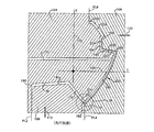
図1には、本発明による長い部品12が使用できるタイプの自動車10が示してある。この図に示すように、部品12は、サイドシルガーニッシュであり、これはまたロッカーパネルと呼ばれることもある。部品12の上部は、隣接車体要素またはその他の外装要素14によって隠されている。
FIG. 1 shows an automobile 10 of the type in which a long part 12 according to the invention can be used. As shown in this figure, part 12 is a side sill garnish, which may also be referred to as a rocker panel. The upper part of the part 12 is hidden by an adjacent vehicle body element or other
図4に示すように、部品12は、底端壁400と頂端壁要素402、404との間に配置された表側主要面領域406を有する長い要素から成る。塗膜200が、表側主要面406の全体を被覆している。塗膜の底部へりまたは底部末端204が、部品の底端の背後に底端壁400に沿って配置されている。脚176と178とが、部品の表側の面から後方に離れて配置してある。塗膜の頂部へり206が、頂端壁要素404に沿う部品の外表面上に配置されている。
As shown in FIG. 4, the part 12 consists of a long element having a front
示されているように、この部品は、Z方向すなわち部品の縦軸と、それぞれ部品の高さおよび幅を示すXおよびY方向とを有する。X、Y、およびZは、互いに直交している。全体として、形状は、実質的に裏返しの“C”であり(あるいは、図面の右側から部品を見た場合、“C”)、ここで“C”は、底端壁、頂端壁、および主要面輪郭によって定められる。通常、頂端壁要素402は、フレームに連結され、上にあるか重ねあわされている部品または装飾部材があるために隠されて見えない。部品の底部側に沿う脚178も、適当なフレームその他に連結されている。見る人は表面406の全部を見ることができる。塗膜の底部へり204は、主要面406の背後で底端壁400に沿って延びているので、見る人は、先行技術の部品では見えることもあった分離線または“波”線を見ることがない。また、塗膜の頂部へり206も、他の部品たとえば図1に示すものによって覆われていて、見る人から隠されているので、見る人はこの頂部へりによって生じる境界線を見ることができない。
As shown, the part has a Z direction, ie the longitudinal axis of the part, and an X and Y direction indicating the height and width of the part, respectively. X, Y, and Z are orthogonal to each other. Overall, the shape is a substantially inverted “C” (or “C” when viewing the part from the right side of the drawing), where “C” is the bottom end wall, top end wall, and main It is determined by the surface contour. Typically, the
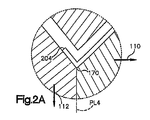
図2および2Aには、先行技術の塗膜被覆“C”形部品の成形に使用できる代表的な先行技術金型構造物を示す。ここでは、100で、この金型キャビティのYまたは幅寸法を示し、102で、この金型キャビティの高さまたはX寸法を示す。Z方向を、XおよびY軸の交点Zで示すが、このZ方向は、図2の平面から外に延びていると理解すべきである。すなわち、X、Y、およびZ方向は互いに直交している。 FIGS. 2 and 2A show a typical prior art mold structure that can be used to form a prior art film coated “C” shaped part. Here, 100 indicates the Y or width dimension of the mold cavity, and 102 indicates the height or X dimension of the mold cavity. The Z direction is indicated by the intersection Z of the X and Y axes, and it should be understood that this Z direction extends out of the plane of FIG. That is, the X, Y, and Z directions are orthogonal to each other.
この金型構造物は、定置雄型要素104、Y方向に動くことのできる雌型要素106、およびX方向に動くことのできるスライダー部分108から成る。雌型要素の雄型要素からの動きまたは引き離しのベクトルを、110で示し、またスライダーの雄型要素から離れる動きのベクトルを、112で示す。
The mold structure comprises a stationary
金型キャビティ140が、金型構造物の雄型、雌型、およびスライダー部分の間に備えられている。この金型キャビティは、150で示す頂端で終わり、またこの金型キャビティの底部側面160で終わっている。この金型キャビティの最下部を、170で示す。これを、金型キャビティの底端とも呼ぶ。第一の後脚176と連結のための第二の後脚キャビティ構造178とが、この底端部分から背後に延び出ている。頂端部分184が、この金型構造物の上部部分として備えられ、また対応する金型キャビティ底端がこの金型構造物の最下点に182で示されている。
A
通常の技術により、塗膜200をキャビティの雌型側面に配置することができる。ここで使用する塗膜という言葉は、広く、必要なプラスチックと同時に成形することのできるすべての装飾フィルムを含むものとする。たとえば、この塗膜は、フィルムラミネートから成ることができ、このラミネートは、カラー、透明、および/または金属光沢もしくは金属粉層(すべて、部品の表側に必要な美的外観を与えることを意図する)とすることのできる複数の層から成る。あるいは、この塗膜は、単一層構造からなることもできる。
The
図に示すように、この塗膜は、表側の面のためのキャビティ180の全体に沿って延びており、塗膜の一端206は頂端キャビティで終わっており、塗膜の底部へり204は底端キャビティで終わっている。示されているように、この金型は三分割金型であって、分割線を、PL2、PL4、およびPL6としてそれぞれ想像線で示す。スプルー210が雄型に備えられ、金型キャビティと連絡している。注意すべきことは、頂端キャビティの一部が頂部棚連結部220キャビティによって定められ、連結部220キャビティは、前方に突き出た棚202を有し、該棚には、上部脚キャビティ224および226が接続している。
As shown, this coating extends along the entire cavity 180 for the front side, one
一般に、この金型キャビティは、三つの主要部分、(a)主要面キャビティ180、(b)底端キャビティ182、および(c)頂端キャビティ184から成る。図2に示すように、塗膜200は表側キャビティの表側(ここでは、雌型側)を覆い、金型の底端および頂端キャビティ部分の204、206で終わっている。
In general, the mold cavity consists of three main parts: (a) a main surface cavity 180, (b) a
図2Aに示す、ある種の先行技術で一般的な方法では、塗膜の末端へり204は、参照番号170で示すように、底端キャビティ内のキャビティの最下部分の後部まで配置されている。この構造は、問題が起こりやすい。というのは、図2Aに示すベクトル線110に沿う雌型要素の引出しまたは引き離しにより、塗膜のこの部分204の引きちぎりまたは引き裂きが起こることが多いからである。
In certain prior art common methods, shown in FIG. 2A, the coating's
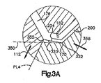
以下、図3および3Aにより、本発明を詳しく説明する。これらの図に示す金型構造物においては、当該金型の底端キャビティ部分182には、底壁面が備えられ、この底壁面は傾斜底壁320を有する(図3A)。底端キャビティの底壁320は、前部境界322から後部境界352まで延びている。図3Aに示すように、底壁320の前部境界322は、接線350に対して約1〜20゜、好ましくは1〜10゜、もっとも好ましくは5゜の角度傾斜している。接線350は、前部境界322に接し、図3に示すY方向線100に平行で、図3に示すX方向に直交している。示されているように、塗膜200の底部へり204は、金型キャビティの最下端170を通過して傾斜底壁320に沿って延びている。本発明の場合、分割線PL4は、傾斜底壁320の末端352に隣接して配置されている。
Hereinafter, the present invention will be described in detail with reference to FIGS. 3 and 3A. In the mold structure shown in these drawings, the bottom
図3からわかるように、図3Aにもっとも良く示されているような傾斜底端キャビティ面が備えられ、雌型引出しまたは引き離しベクトルが358で示されるようなもの(図3)であるので、部品を対応するキャビティから取り出すときに、塗膜のへり204の引きちぎりまたは引っかきを防ぐことができる。言い換えると、雌型要素のY方向引出しまたは移動も、100で示すY方向に対して約1〜20゜の角度でなされる。この角度は、底端キャビティの底壁の前記傾斜角に実質的に一致する。また、図3に示すように、上部棚連結部キャビティ220も、好ましくは、雄型要素から離れる雌型要素のY方向移動が容易になるように前記角度だけ傾けられる。これに対して、図2に示す先行技術の構造物においては、上部棚連結部キャビティ220がX方向に対して実質的に直交している。
As can be seen from FIG. 3, the inclined bottom end cavity surface as best shown in FIG. 3A is provided and the female drawer or pull-off vector is as shown by 358 (FIG. 3) When the film is taken out of the corresponding cavity, tearing or scratching of the
明らかに、本発明は、一つの側面において、実質的に“C”形の断面を有する長い部品の成形のための方法を提供するものである。一般に、この部品は、当該部品の底部へりを定める底端、当該部品の頂部へりを定める頂端、および、前記底端と頂端との間にあって、表側の面と対向後面とから成る主要面から成る。この方法においては、必要な“C”形の断面に一致する金型キャビティが備えられる。この金型キャビティ自体は、Z方向の縦軸に沿って延びており、水平方向Yと垂直方向Xとを有し、X、Y、およびZが互いに直交している。底端キャビティ、頂端キャビティ、および主要面キャビティのすべてが、協同する金型構造物内に備えられ、主要面キャビティは表側前部と対向後部とを有する。底端キャビティ、頂端キャビティ、および主要面キャビティは、協同して、“C”形または裏返し“C”形を定める。傾斜底壁が底端キャビティに備えられ、当該傾斜底壁は、主要面キャビティの表側の面に接する前部境界と主要面キャビティからY方向に離れた位置にある後部境界とを有する。この傾斜底壁は、底端キャビティの前部境界に接し、かつY方向に延びてX方向に直交する接線に対して、約1〜20゜の角度をなすように備えられている。 Obviously, in one aspect, the present invention provides a method for molding long parts having a substantially “C” shaped cross section. In general, this part consists of a bottom end defining the bottom edge of the part, a top end defining the top edge of the part, and a major surface between the bottom end and the top end and comprising a front side surface and an opposing rear surface. . In this method, a mold cavity is provided that matches the required “C” shaped cross section. The mold cavity itself extends along the vertical axis in the Z direction, has a horizontal direction Y and a vertical direction X, and X, Y, and Z are orthogonal to each other. A bottom end cavity, a top end cavity, and a major surface cavity are all provided in a cooperating mold structure, with the major surface cavity having a front front and an opposing rear. The bottom end cavity, top end cavity, and major surface cavity cooperate to define a “C” shape or an inverted “C” shape. An inclined bottom wall is provided in the bottom end cavity, and the inclined bottom wall has a front boundary that contacts a front surface of the main surface cavity and a rear boundary that is located away from the main surface cavity in the Y direction. The inclined bottom wall is provided to contact the front boundary of the bottom end cavity and to form an angle of about 1 to 20 degrees with respect to a tangent line extending in the Y direction and perpendicular to the X direction.
この方法は、金型キャビティ内に溶融プラスチックを射出し、溶融プラスチックを冷却させて成形部品ができるようにすることから成る。得られる冷却プラスチック部品は、金型キャビティから、X方向に対して鋭角をなすように、取り出すか突き出す。 This method consists of injecting molten plastic into the mold cavity and allowing the molten plastic to cool to form a molded part. The resulting cooled plastic part is removed or protruded from the mold cavity to form an acute angle with respect to the X direction.
一般に、塗膜が、金型キャビティ内に、主要面キャビティの表側前面に沿って、当該塗膜の一端が底端キャビティ内に延び出るように、配置されている。示されているように、この金型キャビティは、定置雄型要素、Y方向に動ける可動雌型要素、およびX方向に動けるスライダー部分から成る三分割金型構造物によって定められる。成形部品の金型キャビティからの取り出しは、前記接線に平行で、Y方向に延びている線に対して約1~20゜の角度でY方向に雌型要素を動かすことを含む。したがって、底端キャビティ内に配置されている塗膜のへりは、雌型要素がY方向に動くときに、引っかかれたり、引きちぎられたりすることがない。また、金型のスライダー部分は、雄型要素からX方向に動かされる。 Generally, the coating is positioned in the mold cavity so that one end of the coating extends into the bottom end cavity along the front side of the main surface cavity. As shown, the mold cavity is defined by a three-part mold structure consisting of a stationary male mold element, a movable female mold element movable in the Y direction, and a slider portion movable in the X direction. Removal of the molded part from the mold cavity includes moving the female mold element in the Y direction at an angle of about 1-20 ° with respect to a line parallel to the tangent line and extending in the Y direction. Therefore, the edge of the coating disposed in the bottom end cavity is not scratched or torn off when the female element moves in the Y direction. The slider part of the mold is moved in the X direction from the male element.
本発明による長い自動車部品は、実質的に“C”形の断面形状を有する。この部品は、当該部品の底部へりを定める底端壁部分、当該部品の頂部を定める頂端壁部分、および底端壁部分と頂端壁部分との間に延びる主要面から成る。この主要面は、表側の面と対向後面とから成る。前記底端壁部分は、主要面の表側の面から延び出ていて、また傾斜底壁面を有する。この底壁面は、主要面に隣接する前部境界と主要面から後方に離れた後部境界とを有する。この傾斜底壁は、Y方向に延びてX方向に直交する、前部境界に接する接線に対して、約1〜20゜の角度に配置されている。好ましくは、この傾斜は、約1〜10゜であり、もっとも好ましくは約5゜である。 The long automotive part according to the invention has a substantially “C” shaped cross-sectional shape. The part consists of a bottom end wall part defining the bottom edge of the part, a top end wall part defining the top of the part, and a major surface extending between the bottom end wall part and the top end wall part. This main surface consists of a front side surface and an opposing rear surface. The bottom end wall portion extends from the front surface of the main surface and has an inclined bottom wall surface. The bottom wall surface has a front boundary adjacent to the main surface and a rear boundary spaced rearward from the main surface. The inclined bottom wall is disposed at an angle of about 1 to 20 ° with respect to a tangent line extending in the Y direction and perpendicular to the X direction and tangent to the front boundary. Preferably, this slope is about 1-10 °, most preferably about 5 °.
前記自動車部品は、その好ましい実施形態においては、表側の面全体を覆う塗膜を有するプラスチック基板から成り、この塗膜の第一のへりが、底端壁部分の少なくとも一部を覆い、底端部分の前部境界の後方で終わっている。また、この好ましい実施形態は、底端キャビティの傾斜底壁に沿って前部境界と後部境界との間で終わる塗膜の第一のへりを有している。塗膜の第二のへりは、頂端壁部分の少なくとも一部を覆っている。 In the preferred embodiment, the automobile part comprises a plastic substrate having a coating covering the entire front surface, the first edge of the coating covering at least a portion of the bottom end wall portion and the bottom end. Ends behind the front boundary of the part. This preferred embodiment also has a first edge of the coating that terminates between the front and rear boundaries along the sloped bottom wall of the bottom end cavity. The second edge of the coating covers at least part of the top wall portion.
10 自動車
12 長い部品
14 外装要素
100 金型キャビティの幅方向
102 金型キャビティの高さ方向
104 定置雄型要素
106 雌型要素
108 スライダー部分
110 雌型要素引き離しベクトル
112 スライダー引き離しベクトル
140 金型キャビティ
150 頂端
160 底部側面
170 金型キャビティの最下端
176 第一の後脚
178 第二の後脚
180 主要面キャビティ
182 底端キャビティ
184 頂端キャビティ
200 塗膜
202 棚
204 塗膜の底部へり
206 塗膜の頂部へり
210 スプルー
220 連結部キャビティ
224 上部脚キャビティ
226 上部脚キャビティ
320 傾斜底壁
322 前部境界
350 接線
352 後部境界
358 雌型引き離しベクトル
400 底端壁
402 頂端壁要素
404 頂端壁要素
406 表側主要面
PL2 分割線
PL4 分割線
PL6 分割線
X 部品の高さ方向
Y 部品の幅方向
Z 部品の縦軸
10 cars
12 Long parts
14 Exterior elements
100 Mold cavity width direction
102 Mold cavity height direction
104 Stationary male element
106 Female elements
108 Slider part
110 Female element pull-off vector
112 Slider release vector
140 mold cavity
150 top
160 Bottom side
170 Bottom edge of mold cavity
176 1st hind leg
178 Second hind leg
180 Main face cavity
182 Bottom edge cavity
184 Top cavity
200 coatings
202 shelves
204 Bottom edge of the coating
206 Top edge of coating
210 Sprue
220 Connection cavity
224 Upper leg cavity
226 Upper leg cavity
320 Inclined bottom wall
322 Front boundary
350 Tangent
352 Rear boundary
358 Female Drawer Vector
400 Bottom end wall
402 Top wall elements
404 top wall elements
406 Front side main surface
PL2 dividing line
PL4 dividing line
PL6 dividing line
X Component height direction
Y Part width direction
Z part vertical axis
Claims (16)
当該部品が、当該部品の底部へりを定める底端、当該部品の頂部を定める頂端、当該底端と当該頂端との間に延びている、表側の面と対向後面とを有する主要面、を有する自動車部品である方法において、改良が、
(a)前記“C”形断面と一致するスペースを定める金型キャビティを備え、当該金型キャビティが、Z方向の縦軸に沿って延びており、また水平方向Yと垂直方向Xとを有し、X、Y、およびZが互いに直交し、
(b)前記金型キャビティに、底端キャビティ部分、頂端キャビティ部分、および主要面キャビティ部分を備え、当該主要面キャビティ部分が、表側前部と対向後部とを有し、前記底端キャビティ部分、頂端キャビティ部分、および主要面キャビティ部分が協同して前記“C”形形状を定め、
(c)前記底端キャビティ部分に傾斜底壁を備え、当該傾斜底壁が、前部境界と後部境界とを有し、当該前部境界が前記主要面キャビティ部分の前記表側前部に隣接し、当該後部境界が、前記前部境界に接して前記Y方向に延びて前記X方向に直交する接線に対して約1〜20゜の角度をなすように、前記前部境界からY方向に離れた位置にあり、
(d)溶融プラスチックを前記金型キャビティ内に射出し、
(e)前記溶融プラスチックを冷却させて前記成形部品ができるようにし、
(f)該成形部品を前記金型キャビティから取り出す、
ことから成る、
ことを特徴とする方法。 A method of forming a long automotive part having a substantially “C” shaped cross-sectional shape, comprising:
The part has a bottom end defining the bottom edge of the part, a top end defining the top of the part, and a main surface having a front side surface and an opposing rear surface extending between the bottom end and the top end. An improvement in the method of being an automotive part is
(a) a mold cavity defining a space coinciding with the “C” -shaped cross section, the mold cavity extending along the longitudinal axis in the Z direction, and having a horizontal direction Y and a vertical direction X; X, Y, and Z are orthogonal to each other,
(b) the mold cavity comprises a bottom end cavity portion, a top end cavity portion, and a main surface cavity portion, the main surface cavity portion having a front side front portion and an opposing rear portion, the bottom end cavity portion; The top end cavity portion and the main surface cavity portion cooperate to define the “C” shape;
(c) the bottom end cavity portion is provided with an inclined bottom wall, the inclined bottom wall has a front boundary and a rear boundary, and the front boundary is adjacent to the front front portion of the main surface cavity portion. The rear boundary is spaced in the Y direction from the front boundary such that the rear boundary is in contact with the front boundary and extends in the Y direction and forms an angle of about 1 to 20 degrees with respect to a tangent perpendicular to the X direction. In the position
(d) injecting molten plastic into the mold cavity;
(e) allowing the molded part to be formed by cooling the molten plastic;
(f) removing the molded part from the mold cavity;
Consisting of
A method characterized by that.
当該部品が、当該部品の底部へりを定める底端壁部分、当該部品の頂部を定める頂端壁部分、および当該底端壁部分と当該頂端壁部分との間に延びている主要面を有し、ここで、当該主要面が表側の面と対向後面とを有し、前記部品が、X、Y、およびZ方向に延びており、Zが前記部品の縦軸であり、Yが前記部品の水平方向であり、Xが前記部品の垂直方向であり、X、Y、およびZが互いに直交し、ここで、前記底端壁部分が、前記主要面の前記表側の面から延び出ていて、傾斜底壁面を有し、当該底壁面が、前記主要面に隣接する前部境界と前記主要面から前記Y方向に沿って後方に間隔をとって配置されている後部境界とを有し、前記傾斜底壁面が、前記前部境界に接して前記Y方向に延びて前記X方向に直交する接線に対して約1〜20゜の角度をなすように、配置されている、
ことを特徴とする長い自動車部品。 A long automotive part of the type having a cross-sectional shape substantially "C" shaped or inverted "C" shaped,
The component has a bottom end wall portion defining a bottom edge of the component, a top end wall portion defining a top of the component, and a major surface extending between the bottom end wall portion and the top end wall portion; Here, the main surface has a front surface and an opposing rear surface, the component extends in the X, Y, and Z directions, Z is a vertical axis of the component, and Y is a horizontal of the component. Direction, X is the vertical direction of the part, X, Y, and Z are orthogonal to each other, wherein the bottom end wall portion extends from the front surface of the main surface and is inclined Having a bottom wall surface, the bottom wall surface having a front boundary adjacent to the main surface and a rear boundary spaced rearward from the main surface along the Y direction, and the inclination A bottom wall surface is in contact with the front boundary and extends in the Y direction to form an angle of about 1 to 20 degrees with respect to a tangent line orthogonal to the X direction. As it is arranged,
Long car parts characterized by that.
Applications Claiming Priority (2)
| Application Number | Priority Date | Filing Date | Title |
|---|---|---|---|
| US50545903P | 2003-09-24 | 2003-09-24 | |
| PCT/US2004/028991 WO2005032918A1 (en) | 2003-09-24 | 2004-09-07 | Deep c parts and method of molding |
Publications (1)
| Publication Number | Publication Date |
|---|---|
| JP2007506581A true JP2007506581A (en) | 2007-03-22 |
Family
ID=34421524
Family Applications (1)
| Application Number | Title | Priority Date | Filing Date |
|---|---|---|---|
| JP2006528030A Pending JP2007506581A (en) | 2003-09-24 | 2004-09-07 | Deep “C” shaped parts and molding methods |
Country Status (4)
| Country | Link |
|---|---|
| US (2) | US20070190294A1 (en) |
| EP (1) | EP1667894A4 (en) |
| JP (1) | JP2007506581A (en) |
| WO (1) | WO2005032918A1 (en) |
Families Citing this family (5)
| Publication number | Priority date | Publication date | Assignee | Title |
|---|---|---|---|---|
| US20060154023A1 (en) * | 2002-08-08 | 2006-07-13 | Renji Maki | Side sill trim part and method of molding same |
| US7896397B2 (en) | 2007-12-27 | 2011-03-01 | Honda Motor Co., Ltd. | Single piece side-sill-garnish and mudguard |
| DE102015103006A1 (en) * | 2015-03-03 | 2016-09-08 | Dr. Ing. H.C. F. Porsche Aktiengesellschaft | Side skirts for a motor vehicle with a sill panel |
| DE102016100700A1 (en) * | 2016-01-18 | 2017-07-20 | Cqlt Saargummi Technologies S.À.R.L. | Tool for molding a molding onto an extrudate |
| KR101876097B1 (en) * | 2016-12-23 | 2018-07-06 | 현대자동차주식회사 | Side sill moulding for car and manufacturing method thereof |
Citations (2)
| Publication number | Priority date | Publication date | Assignee | Title |
|---|---|---|---|---|
| JPH11278180A (en) * | 1998-02-17 | 1999-10-12 | Green Tokai Co Ltd | Insert molding method for bumper, locker panel, chin spoiler part for automobile and motor truck, and part manufactured thereby |
| JP2002321309A (en) * | 2001-04-24 | 2002-11-05 | Giken Co Ltd | Plating tone exterior goods for automobile and its manufacturing method |
Family Cites Families (12)
| Publication number | Priority date | Publication date | Assignee | Title |
|---|---|---|---|---|
| US2431414A (en) * | 1944-11-10 | 1947-11-25 | Davis Marinsky | Method of automatically ejecting castings |
| US2432414A (en) * | 1945-04-20 | 1947-12-09 | Eastman Kodak Co | Photographic plate holder |
| US3271501A (en) * | 1965-05-28 | 1966-09-06 | Republic Molding Corp | Method of and means for molding plastic parts |
| US5746962A (en) * | 1995-01-13 | 1998-05-05 | Green Tokai Co., Ltd. | Method of insert molding plastic parts to provide covered edge surfaces |
| US5599608A (en) * | 1995-06-20 | 1997-02-04 | Green Tokai Co., Ltd. | Method of insert molding plastic parts to provide covered edge surfaces and plastic parts made thereby |
| US5759477A (en) * | 1996-12-13 | 1998-06-02 | Green Tokai Co. Ltd. | Method of making fused film plastic parts |
| US5968444A (en) * | 1997-05-16 | 1999-10-19 | Green Tokai Co., Ltd | Method for pre-shaping of plastic films used in co-molding processes and improved paint film covered parts made thereby |
| US6171543B1 (en) * | 1998-04-30 | 2001-01-09 | Tokai Kogyo Co., Ltd. | Rocker panel construction |
| US6436329B1 (en) * | 1999-02-19 | 2002-08-20 | Green Tokai Co., Ltd. | Method of making fused film plastic parts and parts made by such methods |
| US6227319B1 (en) * | 1999-07-01 | 2001-05-08 | Baker Hughes Incorporated | Superabrasive cutting elements and drill bit so equipped |
| JP3681117B2 (en) * | 2001-11-16 | 2005-08-10 | 本田技研工業株式会社 | Divided structure of long resin member in vehicle |
| WO2003066317A1 (en) * | 2002-02-06 | 2003-08-14 | Green Tokai Co., Ltd. | Improved rocker panel and method for minimizing sag lines in molded part |
-
2004
- 2004-09-07 US US10/572,733 patent/US20070190294A1/en not_active Abandoned
- 2004-09-07 JP JP2006528030A patent/JP2007506581A/en active Pending
- 2004-09-07 WO PCT/US2004/028991 patent/WO2005032918A1/en active Application Filing
- 2004-09-07 EP EP04783289A patent/EP1667894A4/en not_active Withdrawn
-
2008
- 2008-08-11 US US12/228,212 patent/US20080305307A1/en not_active Abandoned
Patent Citations (2)
| Publication number | Priority date | Publication date | Assignee | Title |
|---|---|---|---|---|
| JPH11278180A (en) * | 1998-02-17 | 1999-10-12 | Green Tokai Co Ltd | Insert molding method for bumper, locker panel, chin spoiler part for automobile and motor truck, and part manufactured thereby |
| JP2002321309A (en) * | 2001-04-24 | 2002-11-05 | Giken Co Ltd | Plating tone exterior goods for automobile and its manufacturing method |
Also Published As
| Publication number | Publication date |
|---|---|
| EP1667894A1 (en) | 2006-06-14 |
| US20080305307A1 (en) | 2008-12-11 |
| WO2005032918A1 (en) | 2005-04-14 |
| EP1667894A4 (en) | 2009-07-15 |
| US20070190294A1 (en) | 2007-08-16 |
Similar Documents
| Publication | Publication Date | Title |
|---|---|---|
| EP1897669B1 (en) | Die for injection compression molding | |
| US6551540B1 (en) | Method for overmolding sink marks for an automotive component | |
| JP4572883B2 (en) | Interior panel and injection molding method | |
| US6827895B1 (en) | Method of making a plural component show face trim part | |
| JPH11278180A (en) | Insert molding method for bumper, locker panel, chin spoiler part for automobile and motor truck, and part manufactured thereby | |
| US20100052209A1 (en) | Method of manufacturing a component for a vehicle interior | |
| US20080305307A1 (en) | Deep "C" parts and method of molding | |
| US6413460B1 (en) | Method of forming a partially covered panel | |
| JP2005178185A (en) | Injection molding mold and method for producing injection-molded article using the mold | |
| US7344669B2 (en) | Plural color component film laminate part and method of making same | |
| US20070018350A1 (en) | Method of producing a part | |
| US20050236737A1 (en) | Method for locating a decorative piece in a mold and the mold | |
| JPH10323858A (en) | Manufacture of plastic outer shell and bezel | |
| GB2366230A (en) | Plastics moulding | |
| JP3778167B2 (en) | Injection foam molded product and method for producing the same | |
| JP4832103B2 (en) | Method for producing foam integrated with skin having groove pattern | |
| JP3116783B2 (en) | Method for producing coated injection molded article | |
| JP6959709B2 (en) | Resin panel parts and their manufacturing methods | |
| JP3755246B2 (en) | Skin integral molding method | |
| US20070224382A1 (en) | Two-shot molded doors without parting lines | |
| JP7454392B2 (en) | Composite molded product, display device using the composite molded product, and method for manufacturing the composite molded product | |
| JP6350558B2 (en) | Molding method of resin molded products | |
| JPH06143346A (en) | Block ejector pin gate type injection mold | |
| JP2006015633A (en) | Injection foaming mold, injection foam molding method and skinned foamed resin member | |
| JPH07137086A (en) | Molded product such as synthetic resin operation panel with transparent resin coating and production thereof |
Legal Events
| Date | Code | Title | Description |
|---|---|---|---|
| A621 | Written request for application examination |
Free format text: JAPANESE INTERMEDIATE CODE: A621 Effective date: 20070903 |
|
| A977 | Report on retrieval |
Free format text: JAPANESE INTERMEDIATE CODE: A971007 Effective date: 20091111 |
|
| A131 | Notification of reasons for refusal |
Free format text: JAPANESE INTERMEDIATE CODE: A131 Effective date: 20091124 |
|
| A02 | Decision of refusal |
Free format text: JAPANESE INTERMEDIATE CODE: A02 Effective date: 20100427 |