JP2007504493A - Bi-directional display system with matrix photodetector - Google Patents
Bi-directional display system with matrix photodetector Download PDFInfo
- Publication number
- JP2007504493A JP2007504493A JP2006524743A JP2006524743A JP2007504493A JP 2007504493 A JP2007504493 A JP 2007504493A JP 2006524743 A JP2006524743 A JP 2006524743A JP 2006524743 A JP2006524743 A JP 2006524743A JP 2007504493 A JP2007504493 A JP 2007504493A
- Authority
- JP
- Japan
- Prior art keywords
- display system
- exit surface
- inward
- image
- panel
- Prior art date
- Legal status (The legal status is an assumption and is not a legal conclusion. Google has not performed a legal analysis and makes no representation as to the accuracy of the status listed.)
- Withdrawn
Links
Images


Classifications
-
- G—PHYSICS
- G06—COMPUTING; CALCULATING OR COUNTING
- G06F—ELECTRIC DIGITAL DATA PROCESSING
- G06F3/00—Input arrangements for transferring data to be processed into a form capable of being handled by the computer; Output arrangements for transferring data from processing unit to output unit, e.g. interface arrangements
- G06F3/01—Input arrangements or combined input and output arrangements for interaction between user and computer
- G06F3/03—Arrangements for converting the position or the displacement of a member into a coded form
- G06F3/041—Digitisers, e.g. for touch screens or touch pads, characterised by the transducing means
- G06F3/042—Digitisers, e.g. for touch screens or touch pads, characterised by the transducing means by opto-electronic means
- G06F3/0421—Digitisers, e.g. for touch screens or touch pads, characterised by the transducing means by opto-electronic means by interrupting or reflecting a light beam, e.g. optical touch-screen
- G06F3/0423—Digitisers, e.g. for touch screens or touch pads, characterised by the transducing means by opto-electronic means by interrupting or reflecting a light beam, e.g. optical touch-screen using sweeping light beams, e.g. using rotating or vibrating mirror
-
- G—PHYSICS
- G02—OPTICS
- G02B—OPTICAL ELEMENTS, SYSTEMS OR APPARATUS
- G02B6/00—Light guides; Structural details of arrangements comprising light guides and other optical elements, e.g. couplings
- G02B6/04—Light guides; Structural details of arrangements comprising light guides and other optical elements, e.g. couplings formed by bundles of fibres
- G02B6/06—Light guides; Structural details of arrangements comprising light guides and other optical elements, e.g. couplings formed by bundles of fibres the relative position of the fibres being the same at both ends, e.g. for transporting images
- G02B6/08—Light guides; Structural details of arrangements comprising light guides and other optical elements, e.g. couplings formed by bundles of fibres the relative position of the fibres being the same at both ends, e.g. for transporting images with fibre bundle in form of plate
-
- G—PHYSICS
- G06—COMPUTING; CALCULATING OR COUNTING
- G06F—ELECTRIC DIGITAL DATA PROCESSING
- G06F3/00—Input arrangements for transferring data to be processed into a form capable of being handled by the computer; Output arrangements for transferring data from processing unit to output unit, e.g. interface arrangements
- G06F3/01—Input arrangements or combined input and output arrangements for interaction between user and computer
- G06F3/03—Arrangements for converting the position or the displacement of a member into a coded form
- G06F3/033—Pointing devices displaced or positioned by the user, e.g. mice, trackballs, pens or joysticks; Accessories therefor
- G06F3/038—Control and interface arrangements therefor, e.g. drivers or device-embedded control circuitry
- G06F3/0386—Control and interface arrangements therefor, e.g. drivers or device-embedded control circuitry for light pen
-
- G—PHYSICS
- G06—COMPUTING; CALCULATING OR COUNTING
- G06F—ELECTRIC DIGITAL DATA PROCESSING
- G06F3/00—Input arrangements for transferring data to be processed into a form capable of being handled by the computer; Output arrangements for transferring data from processing unit to output unit, e.g. interface arrangements
- G06F3/01—Input arrangements or combined input and output arrangements for interaction between user and computer
- G06F3/03—Arrangements for converting the position or the displacement of a member into a coded form
- G06F3/041—Digitisers, e.g. for touch screens or touch pads, characterised by the transducing means
- G06F3/0412—Digitisers structurally integrated in a display
-
- G—PHYSICS
- G06—COMPUTING; CALCULATING OR COUNTING
- G06F—ELECTRIC DIGITAL DATA PROCESSING
- G06F3/00—Input arrangements for transferring data to be processed into a form capable of being handled by the computer; Output arrangements for transferring data from processing unit to output unit, e.g. interface arrangements
- G06F3/01—Input arrangements or combined input and output arrangements for interaction between user and computer
- G06F3/03—Arrangements for converting the position or the displacement of a member into a coded form
- G06F3/041—Digitisers, e.g. for touch screens or touch pads, characterised by the transducing means
- G06F3/042—Digitisers, e.g. for touch screens or touch pads, characterised by the transducing means by opto-electronic means
-
- G—PHYSICS
- G09—EDUCATION; CRYPTOGRAPHY; DISPLAY; ADVERTISING; SEALS
- G09G—ARRANGEMENTS OR CIRCUITS FOR CONTROL OF INDICATING DEVICES USING STATIC MEANS TO PRESENT VARIABLE INFORMATION
- G09G3/00—Control arrangements or circuits, of interest only in connection with visual indicators other than cathode-ray tubes
- G09G3/001—Control arrangements or circuits, of interest only in connection with visual indicators other than cathode-ray tubes using specific devices not provided for in groups G09G3/02 - G09G3/36, e.g. using an intermediate record carrier such as a film slide; Projection systems; Display of non-alphanumerical information, solely or in combination with alphanumerical information, e.g. digital display on projected diapositive as background
- G09G3/002—Control arrangements or circuits, of interest only in connection with visual indicators other than cathode-ray tubes using specific devices not provided for in groups G09G3/02 - G09G3/36, e.g. using an intermediate record carrier such as a film slide; Projection systems; Display of non-alphanumerical information, solely or in combination with alphanumerical information, e.g. digital display on projected diapositive as background to project the image of a two-dimensional display, such as an array of light emitting or modulating elements or a CRT
-
- H—ELECTRICITY
- H04—ELECTRIC COMMUNICATION TECHNIQUE
- H04N—PICTORIAL COMMUNICATION, e.g. TELEVISION
- H04N5/00—Details of television systems
- H04N5/74—Projection arrangements for image reproduction, e.g. using eidophor
- H04N5/7416—Projection arrangements for image reproduction, e.g. using eidophor involving the use of a spatial light modulator, e.g. a light valve, controlled by a video signal
- H04N5/7458—Projection arrangements for image reproduction, e.g. using eidophor involving the use of a spatial light modulator, e.g. a light valve, controlled by a video signal the modulator being an array of deformable mirrors, e.g. digital micromirror device [DMD]
-
- G—PHYSICS
- G02—OPTICS
- G02B—OPTICAL ELEMENTS, SYSTEMS OR APPARATUS
- G02B6/00—Light guides; Structural details of arrangements comprising light guides and other optical elements, e.g. couplings
- G02B6/24—Coupling light guides
- G02B6/26—Optical coupling means
- G02B6/35—Optical coupling means having switching means
- G02B6/351—Optical coupling means having switching means involving stationary waveguides with moving interposed optical elements
- G02B6/3512—Optical coupling means having switching means involving stationary waveguides with moving interposed optical elements the optical element being reflective, e.g. mirror
-
- G—PHYSICS
- G02—OPTICS
- G02B—OPTICAL ELEMENTS, SYSTEMS OR APPARATUS
- G02B6/00—Light guides; Structural details of arrangements comprising light guides and other optical elements, e.g. couplings
- G02B6/24—Coupling light guides
- G02B6/26—Optical coupling means
- G02B6/35—Optical coupling means having switching means
- G02B6/3586—Control or adjustment details, e.g. calibrating
- G02B6/3588—Control or adjustment details, e.g. calibrating of the processed beams, i.e. controlling during switching of orientation, alignment, or beam propagation properties such as intensity, size or shape
-
- Y—GENERAL TAGGING OF NEW TECHNOLOGICAL DEVELOPMENTS; GENERAL TAGGING OF CROSS-SECTIONAL TECHNOLOGIES SPANNING OVER SEVERAL SECTIONS OF THE IPC; TECHNICAL SUBJECTS COVERED BY FORMER USPC CROSS-REFERENCE ART COLLECTIONS [XRACs] AND DIGESTS
- Y10—TECHNICAL SUBJECTS COVERED BY FORMER USPC
- Y10S—TECHNICAL SUBJECTS COVERED BY FORMER USPC CROSS-REFERENCE ART COLLECTIONS [XRACs] AND DIGESTS
- Y10S385/00—Optical waveguides
- Y10S385/901—Illuminating or display apparatus
Abstract
ディスプレイシステムは、入口面と反対側の出口面とを備えた導波路光学パネルを有する。画像ビームは、出口面上に表示するために、入口面を横切って、横方向及び横断方向に投射される。出口面上の内側に向かう光スポットの対応する横方向及び横断方向の位置を検出するために、複数の検出器要素のマトリクスを有する光検出器が入口面と光学的に整列される。 The display system has a waveguide optical panel with an entrance surface and an exit surface on the opposite side. The image beam is projected laterally and transversely across the entrance surface for display on the exit surface. In order to detect the corresponding lateral and transverse positions of the inwardly directed light spot on the exit surface, a photodetector having a matrix of detector elements is optically aligned with the entrance surface.
Description
連邦政府によって援助された研究又は開発に関する記述
本発明は、エネルギー省によって与えられた契約番号DE−AC02−98CH10886による政府支援をもってなされた。政府は、本発明に一定の権利を有する。
DESCRIPTION OF FEDERALLY SPONSORED RESEARCH OR DEVELOPMENT This invention was made with government support under contract number DE-AC02-98CH10886 awarded by the Department of Energy. The government has certain rights in the invention.
発明の背景
本発明は、一般には、光導波路、より詳細には、それで形成された光学パネルに関する。
BACKGROUND OF THE INVENTION This invention relates generally to optical waveguides, and more particularly to optical panels formed therefrom.
米国特許第5,381,502号は、互いに積層された複数のリボン状光導波路を有する多平面光学ディスプレイ(POD:polyplanar optical display)を開示している。画像光は、その中での全内部反射(全反射)のために、ディスプレイの入口面を通して投射され、パネルの反対側の出口面端部においてビデオ(映像、テレビ)画像が表示される。 U.S. Pat. No. 5,381,502 discloses a polyplanar optical display (POD) having a plurality of ribbon-like optical waveguides laminated together. The image light is projected through the entrance surface of the display for total internal reflection (total reflection) therein, and a video (video, television) image is displayed at the end of the exit surface opposite the panel.
米国特許第5,455,882号は、双方向(インタラクティブ)動作のために構成された別の形態のPODパネルを開示している。ビデオ画像は、積み重ねられた複数の導波路を通して外側に向けて投射される。又、双方向性光ビームを、出口面を通して入口面へと内側に向けて指向させることができ、そのスクリーン上の位置を、双方向機能を提供するために検出することができるようになっている。 US Pat. No. 5,455,882 discloses another form of POD panel configured for interactive operation. The video image is projected outward through a plurality of stacked waveguides. Also, the bidirectional light beam can be directed inward through the exit surface to the entrance surface, and its position on the screen can be detected to provide a bidirectional function. Yes.
いずれの特許においても、同様に構成された光学パネルが、入口面から反対側の出口面への方向、出口面から反対側の入口面への方向のいずれの方向における光伝達(透過)も可能とする。この能力は、テレビジョン用の高解像度表示画面(ビューイングスクリーン)、コンピュータモニタ、及び所望により種々のその他のタイプの表示画面を提供するために、光学パネルを種々の用途において用いることを可能とする。 In any patent, a similarly configured optical panel can transmit (transmit) light in either direction from the entrance surface to the opposite exit surface, or from the exit surface to the opposite entrance surface. And This capability allows the optical panel to be used in a variety of applications to provide high resolution display screens (viewing screens) for televisions, computer monitors, and various other types of display screens as desired. To do.
種々の形態のディスプレイスクリーンとの双方向性を提供するために、別個の機械的なキーボードが一般的に知られている。しかしながら、機械的なキーボードは、システムのサイズ、複雑さ、及びコストを増大させる、付加的な構成部品である。 Separate mechanical keyboards are commonly known to provide interactivity with various forms of display screens. However, a mechanical keyboard is an additional component that increases the size, complexity, and cost of the system.
従来のタッチスクリーンは、双方向機能のための別の方法を提供する。タッチスクリーンは、出口面に被せられる種々の形態を有していてよく、又タッチスクリーンの種々の部分を単に押すことによって双方向性を提供することができる。触れられたスポットの位置は、システムによって判定され、又タッチスクリーンを通して出口面によって表示される双方向オプションに対応する。タッチスクリーンは、独立した装置であり(即ち、出口面から分離されている)、これはシステムの複雑さ及びコストを増大させる。 Conventional touch screens provide another way for interactive functionality. The touch screen may have various forms over the exit surface and can provide interactivity by simply pressing various portions of the touch screen. The location of the touched spot is determined by the system and corresponds to an interactive option displayed by the exit surface through the touch screen. The touch screen is an independent device (ie, separated from the exit surface), which increases the complexity and cost of the system.
従って、実施するにあたり相当の利点を有する双方向機能を備えたディスプレイシステムを提供することが求められている。 Accordingly, there is a need to provide a display system with a bi-directional function that has significant advantages in implementation.
本発明のディスプレイシステムは、入口面と反対側の出口面とを備えた導波路光学パネルを有する。画像ビームは、パネルの出口面上に表示するために、パネルの入口面を横切って、横方向及び横断方向に投射される。出口面上の内側に向かう光スポットの対応する横方向及び横断方向の位置を検出するために、複数の検出器要素のマトリクスを有する光検出器がパネルの入口面と光学的に整列される。 The display system of the present invention has a waveguide optical panel with an entrance surface and an exit surface opposite the entrance surface. The image beam is projected laterally and transversely across the panel entrance surface for display on the panel exit surface. A photodetector having a matrix of detector elements is optically aligned with the entrance surface of the panel to detect corresponding lateral and transverse positions of the inwardly directed light spot on the exit surface.
本発明を、好ましく又典型的な実施形態に従って、その更なる目的及び利点と共に、以下の詳細な説明において添付の図面と関連して更に詳しく説明する。 The invention, together with further objects and advantages thereof, according to preferred and exemplary embodiments, will be described in more detail in the following detailed description in conjunction with the accompanying drawings.
好ましい実施形態の詳細な説明
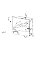
図1は、本発明の典型的な一実施形態に従う双方向性ディスプレイシステム10を示す。ディスプレイシステム10は、複数のリボン状光導波路14を備えた光学ディスプレイパネル12を含む複数の構成部品の組み立て体である。各導波路14は、パネル12の横方向、即ち、水平方向の幅の全体にわたって延在する。又、複数の導波路14は、垂直方向、即ち、横断方向に互いに積み重ねられ、パネル12の高さの全体を規定する。
Detailed Description of the Preferred Embodiment FIG. 1 illustrates an interactive display system 10 according to an exemplary embodiment of the present invention. The display system 10 is an assembly of a plurality of components including an
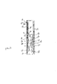
光学パネル12は、例えばベリグダン(Veligdan)に対する米国特許第5,381,502号に示される、サイズを減少させる楔形などの、種々の方法にて配置された複数の導波路を有する、任意の従来の形態を有していてよい。図2に示すように、複数の導波路14は、好ましくは、実質的に同一のサイズを有し、一列に互いに垂直方向に積み重ねられる。複数の導波路14は、それらの第1の、即ち、後方の各端部が、集合的に平坦な入口面16を画成し、又それらの反対側の第2の、即ち、前方の各端部が、集合的に平坦な表示出口面18を画成する。
The
図3により詳細に示すように、各導波路14は、クラッド層14bの間に配置された光学的に透明なコア14aを有する。コア14aとクラッド14bとの間の屈折率の違いによって、画像光ビーム20を、従来の方法の全反射で、個々の導波路14を通して導くことができる。図2に示すように、画像ビーム20は、図1に示される画像(又は、ビデオ画像)22として出口面18上に表示するために、入口面16上に投射される。
As shown in more detail in FIG. 3, each waveguide 14 has an optically transparent core 14a disposed between the cladding layers 14b. Due to the difference in refractive index between the core 14a and the cladding 14b, the
図3に示すように、クラッド14bは、ディスプレイシステム10と相互作用(対話)する観察者、即ち、使用者によって観察された時の画像のコントラストを増強するために、好ましくは、暗色(例えば、黒色)である。 As shown in FIG. 3, the cladding 14b is preferably dark (e.g., to enhance image contrast when viewed by a viewer interacting with the display system 10, i.e., a user). Black).
図1及び図2に初めに示すように、ディスプレイシステム10の種々の構成部品は、好ましくはディスプレイ10に必要なスペースを最小化するために比較的薄型の、適当なハウジング24内に取り付けることができる。入口面16がパネル12の幅及び高さの全体にわたって延在しているので、入射画像光20を再指向(リダイレクト)させてハウジング24に必要な奥行き(深さ)を最小化するように、光結合器(ライトカプラ)26を入口面16上に付加的に設けることが望ましい。
As initially shown in FIGS. 1 and 2, the various components of the display system 10 are preferably mounted within a
好ましい一実施形態では、結合器26は、パネル12の幅全体に沿って直線状で、且つ、パネル12の高さ方向に沿って垂直に離隔された複数のフレネルプリズム式微小溝(Fresnel prismatic microscopic grooves)を有する。結合器26の好ましい形態は、3M カンパニー[ミネアポリス セントポール]から商品名TRAF IIとして市販されている透過型直角フィルム(TRAF:Transmissive Right Angle Film)である。このTRAFフィルムは、画像光20を、光学パネル12の背面上に小さく鋭い角度にて投射し、次いで複数の導波路14を通して導いて出口面18から表示させるように約90度までの角度で再指向させることを可能とする。ビスカーディ(Biscardi)らに対する米国特許第6,301,417号に記載されるタイプである、その他のタイプの結合器も代わりに用いることができる。或いは、結合器26は省略することができ、画像ビームは典型的なリアプロジェクション(背面投射)方式にて入口面に直接向けることができる。
In one preferred embodiment, the
光学パネル12は、その入口面側と出口面側との間でいずれの方向においても光が内部を伝達(透過)され得る複数の積み重ねられた光導波路を利用した、任意の適当な構成を有していてよい。図2及び図4に模式的に示すように、光学パネル12は、適当な光投射器(プロジェクタ)28と協働するようにハウジング24内に取り付けられる。この光投射器28は、任意の所望のビデオ画像22を形成するのに用いられる光を投射するための、任意の従来の構成を有する。投射器28から出る光は、好ましくは、散乱光よりはむしろビームの形態である。
The
例えば、投射器28は、白色光を生成するためのランプを有していてよい。この白色光は、出口面18上に任意の所望のビデオ画像22を生成するのに用いるための適当な投射レンズを通して投射される。例えば、投射器28の内部又は外部において既知の方法にて従来のカラーホイールを回転させることによって、光ビームに色彩を加えてもよい。
For example, the
投射器28は、所望のビデオ画像をデジタル的に生成するために、好ましくは、デジタル結像装置(イメージングデバイス)30と協働する。任意の適当なデジタル結像装置を使用することができるが、デジタルマイクロミラーデバイス(DMD:Digital Micromirror Device)結像装置30が好ましい。DMD30は、投射器28と入口面16との間に光学的に整列される結像装置であり、これは画像ビーム20を協働する投射レンズ32を通して選択的に反射させてビデオ画像を形成する。この結像装置30は、例えば、何千もの微小サイズの結像ミラー(microscopically sized image mirrors)34のマトリクスアレイを有する小さな半導体光スイッチである。各ミラー34は、駆動された時に典型的には±10度の角度範囲で前後に独立して傾斜されるように、ヒンジ上に取り付けられている。駆動されていない時には、個々のマイクロミラー34は、中間の弛緩位置をとる。DMD30は、テキサス インスツルメンツ インコーポレイテッド[テキサス州 ダラス]から市販されている従来の装置である。これは、種々の用途のためにデジタル画像を生成する際に、デジタル光プロセスにおいて使用するためのものである。
DMD結像装置30は、その中の何千ものマイクロミラー34の各々を独立して制御するために用いられる従来の電子的ドライバ36と協働するものとして、図4に模式的に示されている。結像装置30は、ドライバ36を介して電気的コントローラ38に動作可能に結合されている。これにより、結像装置30の動作、及びパネル12上に表示されるビデオ画像22の形成を制御できるようになっている。
The
コントローラ38は、任意の適当な目的のために任意の所望のビデオ画像を表示するための適当なソフトウェアでプログラムされたデジタルマイクロプロセッサなどの、任意の従来の構成をとることができる。コントローラ38は、普通のテレビジョンビデオ画像をパネル12から表示するため、或いは典型的にはコンピュータモニタ、現金自動預け払い機(ATM)等の上に表示されるその他のビデオ画像を表示するために用いることができる。
The
本開示の目的で、「外側に向かう(外側に向ける)(outbound:アウトバウンド)」なる用語は、入口面16から出口面18に向かう方向であるとして定義し、「内側に向かう(内側に向ける)(inbound:インバウンド)」なる用語は、出口面18から入口面16に向かう方向であるとして定義する。
For the purposes of this disclosure, the term “outbound” is defined as the direction from the
図2及び図4に示すように、好ましくは、結像装置30とパネル12との間の外側に向かうビームの経路内において、折り返し(フォールディング)ミラー40が用いられる。これにより、コンパクトな構成を提供すると共に、外側に向かう画像ビームを小さく鋭い入射角にて再指向させることができる。この外側に向かう画像ビームは、光結合器26によって向きを変えることができる。投射レンズ32は、好ましくは、折り返しミラー40の上流側ビーム(upbeam)及び下流側ビーム(downbeam)に対応して配置された、単一又は複数のレンズの2つの群に形成され、画像ビームを、パネルの入口面の全体にわたって、結合器26によってその中に再指向されたときに、適当に結像させる。
As shown in FIGS. 2 and 4, a
図4は、本発明のディスプレイシステムの基本的な動作を示す。ここでは、コントローラ38が、電子的ドライバ36を適当に操作して、出口面18上に投射される任意の所望のビデオ画像22を生成するように結像装置30内の種々のマイクロミラー34を位置付けることができるようになっている。結像装置30は、画像ビーム20を生成するために、投射器28から放射された光ビームを空間的及び時間的に変調する。画像ビーム20は、投射レンズ32を通して結像され、光学パネル12を通した最終的な再指向のために折り返しミラー40によって光結合器26にわたって再指向されて、パネルの出口面18上に表示されるようになっている。
FIG. 4 shows the basic operation of the display system of the present invention. Here, the
光学パネル12は、それを通した外側に向かう光伝達、それを通した内側に向かう光伝達のいずれも可能とするので、同じパネルを、任意の所望のビデオ画像を表示すること及び使用者による双方向機能を提供することの両方のために用いることができる。図4に示す典型的なビデオ画像は、任意の所望の用途のために使用者によって選択され得る適当な選択肢のメニューである。例えば、光学パネルは、意図される使用者からの指示を受け取るプロジェクションTV、コンピュータモニタ又はATM機の部分であってよい。システムとの相互作用のために別個且つ専用のキーボードを設ける代わりに、光学パネル12自体を本発明に従って使用することができる。
The
図4に示す画像ビームで生成されたメニューに応答して、光スポットの形態の内側に向かうプローブ光ビーム42が、選択された出口面18の幅方向に沿う横方向位置X及び出口面18の高さ方向に沿う横断方向位置Yにおいてパネル上に適当に形成され、これにより所望のメニュー選択を確認できるようになっている。
In response to the menu generated with the image beam shown in FIG. 4, the
出口面上の内側に向かう光スポットの対応する横方向及び横断方向の位置を光学的に検出するために、複数の光検出器要素の2次元アレイ、即ち、マトリクス(行列)を有する光検出器(オプティカルディテクタ)44が、入口面16と適当に光学的に整列される。結像装置30は、2次元ビデオ画像22を出口面18上に生成するように特別に構成されているので、光検出器44は、プローブ光スポットの2次元位置X、Yを検出するように相応に構成される。プローブ光スポットは、所望により専用の出口面の一部又は全出口面のいずれにあってもよい出口面上の任意の位置にある。
Photodetector having a two-dimensional array, i.e. a matrix, of a plurality of photodetector elements for optically detecting the corresponding lateral and transverse positions of the inwardly directed light spot on the exit face An (optical detector) 44 is suitably optically aligned with the
図4に示すように、光検出器44は、好ましくは、パネルから離隔して配置される。又、光検出器44は、スペースが許すハウジング内の任意の所望の位置において、入口面16から適当に離間され且つ入口面16の背後に配置される。好ましい一実施形態では、各投射レンズ32は、外側に向かう画像ビームを出口面上に集束(フォーカシング)させると共に、内側に向かうプローブビーム42を、外側に向かう画像ビームとは反対方向の内側に向けて検出器44上に結像させるように構成される。
As shown in FIG. 4, the
この構成では、適当なビームスプリッター(ビーム分割器)46が、投射器28から入口面16への外側に向かうビームの経路内における、隣接する投射レンズ32と結像装置30との間の一直線の経路内で光学的に整列される。その最も単純な形態においては、ビームスプリッターは、外側に向かうビームの経路に対して45°の角度が付けられたクリア(透明)なガラスの板であってよい。このビームスプリッターは、これはそれを通した外側に向かう画像ビームの透過(伝達)を可能とする。その他のタイプのビームスプリッターを代わりに利用することもできる。
In this configuration, a
これに対して、スプリッター46から反射された内側に向かうプローブビーム42を受容するために、光検出器44もビームスプリッター46と光学的に整列される。この方法では、結像装置30及び光検出器44の両方が、共通のビームスプリッター46によって、スクリーンへの及びスクリーンからの第1のビーム経路と光学的に整列されている。
In contrast, the
外側に向かう画像ビームは、出口面18上に表示するために、ビームスプリッター46を通して容易に伝達される。又、内側に向かうプローブビーム42は、好ましくは、それがビームスプリッター46において転向されて(そらされて)、光検出器44に向けて指向されるまでは、実質的に外側に向かう画像ビームと共通の光学経路内において、パネルから伝達される。
The outward image beam is easily transmitted through the
この方法では、各レンズ32は、外側に向かう画像ビーム20を投射すると共に、内側に向かうプローブビーム42をも単一の経路のレンズ系(システム)内にて結像させることにおける、共通の機能のために用いることができる。これにより、ディスプレイシステム全体の複雑さ及びスペース的要求を低減することができるようになっている。外側に向かう光ビーム及び内側に向かう光ビームは、所望により同時に伝達してもよいし、或いは時間的に適宜交替させてもよい。いずれの構成においても、内側に向かうプローブビーム42は、ビームスプリッター46によって外側に向かう画像ビーム20の経路から効果的に分割されて、光検出器44へと指向される。
In this method, each
投射レンズ32は、本質的に、出口面にて形成された光スポットを光検出器44上の対応する位置上に結像させるために有効であり、これによりプローブビームの横方向及び横断方向の位置を容易に判定することができる。
The
投射レンズ32の機能は、好ましくは、結像装置30にて生成された画像ビーム20を、より大きな入口面16を満たすために必要とされる、より大きなサイズへと拡大及び集束させることである。これに対して、同一の投射レンズ32を、出口面上の任意の位置からのプローブビーム42を、より小さいサイズの光検出器44へと縮小及び集束させて、その検出効率を最大化するために用いることができる。検出器44内の複数の光学要素のマトリクスアレイは、好ましくは、出口面18の所望の領域との空間的な対応関係を有し、これにより光検出器44上の横方向及び横断方向の空間座標X、Yを、出口面上の光スポット42の位置の横方向及び横断方向の座標X、Yに直接対応させることができる。
The function of the
電気的コントローラ38は、好ましくは、デジタル的にプログラム可能なコンピュータの形態であり、これは、パネルを通して内側に向けて伝達された時に出口面にて検出された光スポットの横方向及び横断方向の位置を判定するように、光検出器44に動作可能に結合される。
The
光検出器44は、好ましくは、比較的小さく、又出口面よりも小さいので、検出器44上に結像されたスポットの対応する位置を検出することによって出口面における光スポットの2次元的な位置を容易に判定できるように、光検出器44は、出口面に対して相対的なスケールとすることができる。検出器44のサイズ及び構成は、出口面の全表面領域に直接対応するように選択してもよいし、或いはその中で双方向機能が望まれる出口面の任意の所望の部分に対応するスケールとしてもよい。
The
例えば、外側に向かうビーム及び内側に向かうビームの両方のために共通の投射レンズ32が用いられる場合には、検出器44は、結像装置30とほぼ同じサイズとすることができる。或いは、検出器44は、結像装置30と比べて、より小さくても、より大きくてもよい。これらの場合には、1つ以上のレンズなどの、図4に示す対応する光学要素48を、ビームスプリッター46と検出器44との間に光学的に整列させることができる。これにより、内側に向かうプローブビーム42を所望に応じて縮小又は拡大(又、任意に、更に集束)させて、検出器のサイズ及び構成を、出口面18のそれに適合させることができるようにする。より小さい検出器の利点は、対応するそのコストの低減であり、これはディスプレイシステムの全体のコストを低減させる。
For example, if a
デジタル結像装置30は、スプリッター46と、画像ビームを複数の画素、即ち、ピクセルの2次元アレイとして形成するための投射器28又は任意の光源との間に光学的に整列される任意の適当な形態を有していてよい。これらのピクセルは、出口面上に最終的なビデオ画像を生成するために、各レンズ32を通して投射される。
The
これに対して、光検出器44内の各検出器要素は、結像装置30内の複数のピクセルの2次元アレイ、並びに、出口面18上に表示されるそれらのピクセルに対応する2次元アレイとして同様に配列されている。この方法では、出口面18上のピクセルの位置と、光検出器44内の検出器要素の対応する空間的位置との間に、直接的相関関係が提供される。出口面18上の任意の所望の位置にプローブ光スポットを形成することによって、光スポットは、プローブスポットの横方向及び横断方向の正確な位置を判定するために、光検出器44のマトリクスアレイ内の対応する空間的位置にて検出される。
In contrast, each detector element in the
図4に示すコントローラ38は、ドライバ36の動作を制御するためにも用いられるので、表示された画像22の空間的位置は、コントローラによって知られる。従って、コントローラは、ディスプレイシステムと相互作用するために使用者がその中に光スポットを形成することができる領域をスクリーン上に表示するように、適当にプログラムすることができる。
Since the
図4では、相互作用のための4つの考えられる選択肢を示す4つのボックスが出口面18上に表示されている。光スポットは、選択Cのためのボックス内に形成されており、対応するプローブビームは、出口面から空間的位置X、Yを判定する光検出器44へと内側に向かって伝達されている。そして、コントローラ38は、検出されたプローブビームの位置を、表示されたビデオ画像と比較して、ディスプレイに双方向性のフィードバックを提供するように適当に構成されている。
In FIG. 4, four boxes are displayed on the
図5は、光学パネルを通して内側に向けて伝達させ、又光検出器により内側に向けて結像させるように、出口面18上に光スポットを投射するために用いることのできる光学ポインタ50を示す。ポインタ50は、電池式で内部に適当な光投射器を有する典型的なテレビ遠隔制御(リモートコントロール)装置と同様に構成されていてよい。好ましい一実施形態では、主に可視光である画像ビームに対する識別(弁別)性を増強するために、プローブビームは赤外(IR)光である。検出器が、内側に向かうプローブビームと、バックグラウンド、即ち、動作中に普通に出口面18に入る外来の(異質な)光又は画像ビーム20自体に由来してパネル12内に見られる外来の光と、を識別(弁別)する能力を増強するために、プローブビーム(例えば、IR)を変調することができる。
FIG. 5 shows an optical pointer 50 that can be used to project a light spot onto the
光検出器44は、好ましくは、IR光を検出するように構成された複数のフォトダイオードの2次元アレイであり、好ましい一実施形態では、ビデオカメラにおいて一般的に見られる電荷結合素子(CCD)の形態であってよい。この方法では、可視画像ビームは、IRプローブビーム42が内側に向けて同時に投射されている間に、外側に向けて出口面上に投射することができる。この実施形態におけるビームスプリッター46は、好ましくは、ダイクロイックミラー(2色性ミラー)であり、これは内側に向かうIRビームを検出器44へと反射させる一方で、外側に向かう可視ビームの透過(伝達)を可能とする。従って、双方向機能は、可視ビームとIRプローブビームとの間の十分な識別を伴うビデオ画像の投射と同時に達成することができる。
別法によれば、ポインタ50は、双方向機能を提供するために、時間的及び/又は空間的に外側に向かう画像ビームから分離することのできる可視光(又は、可視光及びIR光の両方)を投射するように構成することができる。同一の導波路14を、外側に向かう可視ビーム及び内側に向かうプローブビームの両方を伝達するために用いることができるので、例えば2つの光ビームのための異なる導波路を提供すること、時間的及び/又は空間的にそれらの間を分離することのいずれかによるなどして、これらの2つのビーム間を適当に識別することが望まれる。又、上述の実施形態のようにポインタ50がIR光のみを投射するように構成されている場合には、同様の識別技術を採用することができる。 Alternatively, the pointer 50 is visible light (or both visible light and IR light) that can be separated from the outwardly and temporally image beam to provide a bi-directional function. ). The same waveguide 14 can be used to transmit both the outward visible beam and the inward probe beam, for example providing different waveguides for the two light beams, temporally and It is desirable to properly distinguish between these two beams, such as by either separating them spatially. Further, when the pointer 50 is configured to project only IR light as in the above-described embodiment, a similar identification technique can be employed.
図6は、本発明の更に別の実施形態を示す。ここでは、出口面において外側に向かう画像ビームの少なくとも一部を反射させて内側に向かうプローブビーム42を形成するために、使用者の指を出口面18に触れるように使用することができる。出口面18は、外側に向かう画像ビームの少なくとも一部を内側に向けて反射させるために、例えば、指、掌(又はその他の身体部分)、ペンシルイレイザー、スタイラス(針)(即ち、好ましくは先の尖っていないタイプのもの)、又は紙(例えば、バーコード読み取り目的のため)で覆う(カバーする)ことができる。カバー要素(covering element)は、出口面18に直接接触するようにしても、或いは出口面18に非常に接近して離間された反射面を提供するようにしてもよい。
FIG. 6 shows yet another embodiment of the present invention. Here, the user's finger can be used to touch the
この実施形態では、投射器28は、画像ビームを可視光及び赤外光の両方で投射するように構成することができ、ビームスプリッター46はダイクロイックミラーとすることができる。画像ビームの可視成分及び赤外成分の両方が、光学パネルを通して外側に向けて投射され、その出口面上に可視ビデオ画像を形成するようになっている。使用者の指は、出口面の任意の所望の位置を触れて、出口面における複数の導波路のうちのいくつかを覆い、画像ビームの少なくとも一部をプローブビームとして内側に向けて反射させるために使用することができる。
In this embodiment, the
複数の導波路のうちの交互の各1つを、外側に向かう画像ビームと反射された内側に向かうプローブビームとのそれぞれのための専用にすることができる。そして、光検出器44は、内側に向かう光のための専用の各導波路を観察して、使用者の指による光反射を示す、任意の戻るIR光を検出するために用いることができる。この方法では、反射されたプローブビームは、双方向機能を提供するべく画像ビームの反射された部分の横方向及び横断方向の位置を判定するために用いることができる。勿論、別法として、外側に向かう画像ビーム及び反射された内側に向かうプローブビームの両方を、同一の導波路内で伝達することもできる。
Each alternate one of the plurality of waveguides can be dedicated for each of the outwardly directed image beam and the reflected inwardly directed probe beam. The
図5は、外側に向かう画像ビーム20を出口面18上に投射するために、各投射レンズ32を1つの光学経路内で使用することができる本発明の別の実施形態を示す。又、内側に向かう光スポットを外側に向かうビデオ画像とは独立して結像及び検出するために、別個の結像レンズ32B及び対応する折り返しミラー40Bが、各投射レンズ32から離間されている。光結合器26は、入射光を、実質的に反対の鋭い角度にて、その複数のプリズム式溝から受容することができるので、結像レンズ32Bは、結合器26に対して上向きの鋭角にて光学的に整列させることができ、又投射レンズ32は、結合器26に対して実質的に反対(逆向き)の下向きの鋭角にて光学的に整列させることができる。
FIG. 5 illustrates another embodiment of the invention in which each
この方法では、画像ビームは、結合器26の表面領域上に上方に向けて投射することができ、一方内側に向かうプローブビーム42は、結合器26から上方に向けて部分的に偏向されて、結合器26と整列された協働する光検出器44B上に結像させ得るようになっている。図5は、説明の容易化のために、2つの光検出器44及び44Bを示す。しかし、特定の一実施形態においては、どちらかの光検出器と対応する光学部品とを好適に用いることができる。或いは、複数の光検出器及び複数の対応する光学部品の両方の使用も企図し得る。
In this manner, the image beam can be projected upward onto the surface area of the
以上に開示した種々の実施形態において用いられる光学パネル12は、外側に向かう光及び内側に向かう光の両方を伝達することができるので、単に、2次元マトリクスアレイ光検出器44を導入することで、双方向機能を提供することができる。適当な結像レンズ系を、光学パネルの入口面からのプローブスポットを、光学パネルとの間に対応する空間的配向性を有する光検出器上に結像させるために使用することができる。好ましくは赤外光を用いて、空間的及び時間的な双方向機能を同時に達成することができる。或いは、双方向性は、プローブビームを、表示されたビデオ画像から空間的及び/又は時間的に分離することによって達成することができる。
Since the
種々の形態の光投射器を、2次元ビデオ画像を表示するために用いることができる。DMD装置を用いてデジタル的に形成された画像が好適である。又、デジタルビデオ画像は、例えば、液晶ディスプレイ(LCD)又は発光ダイオード(LED)を用いた別の方法で形成することもできる。所望により、投射器は、代わりに従来のスライドプロジェクタの形態であってもよい。 Various forms of light projectors can be used to display two-dimensional video images. Images formed digitally using a DMD device are preferred. The digital video image can also be formed by another method using, for example, a liquid crystal display (LCD) or a light emitting diode (LED). If desired, the projector may instead be in the form of a conventional slide projector.
デジタルビデオ画像は、表示された各ピクセルと、マトリクスアレイ検出器によって検出された内側に向かうプローブビームとの間の対応付けを改善するために好適である。マトリクス検出器は、双方向機能を提供するために、出口面の任意の所望の部分又は全出口面と整列させることができる。又、好ましい一実施形態では、出口面上のスポットの空間的位置の正確な判定のために、同一の投射レンズ系が、内側に向かうプローブビームを光検出器上に結像させるためにも用いられる。 The digital video image is suitable for improving the correspondence between each displayed pixel and the inward probe beam detected by the matrix array detector. The matrix detector can be aligned with any desired portion of the exit face or the entire exit face to provide a bidirectional function. In one preferred embodiment, the same projection lens system is also used to image the inward probe beam onto the photodetector for accurate determination of the spatial position of the spot on the exit surface. It is done.
以上、本明細書では、本発明の好ましく又典型的であると思われる実施形態について説明したが、本明細書の教示から当業者には本発明のその他の変更態様が明らかである。従って、添付の特許請求の範囲が、本発明の真の精神及び範囲内にあるそのような変更の全てを包含することを望む。 In the foregoing specification, the preferred and typical embodiments of the invention have been described. However, other modifications of the invention will be apparent to those skilled in the art from the teachings herein. Accordingly, it is desired that the appended claims encompass all such modifications as fall within the true spirit and scope of the invention.
従って、添付の特許請求の範囲によって規定され、又差別化される発明について特許を請求する。 We therefore claim patents for inventions which are defined and differentiated by the accompanying claims.
Claims (44)
前記出口面上に表示するために前記入口面を横切って横方向及び横断方向に画像光ビームを投射するための投射器と、
前記出口面上の内側に向かう光スポットの対応する横方向及び横断方向の位置を検出するために、前記入口面と光学的に整列された、複数の検出器要素の2次元アレイを有する光検出器と、
を有することを特徴とするディスプレイシステム。 An optical panel having a plurality of optical waveguides stacked on top of each other, each first end thereof defining an entrance surface and each opposite end defining an exit surface;
A projector for projecting an image light beam transversely and transversely across the entrance surface for display on the exit surface;
Light detection with a two-dimensional array of detector elements optically aligned with the entrance surface to detect corresponding lateral and transverse positions of the inwardly directed light spot on the exit surface And
A display system comprising:
前記結像レンズは、前記内側に向かう光スポットを前記画像ビームとは独立して結像させるために、前記投射レンズから離間していることを特徴とする請求項6に記載のディスプレイシステム。 And a projection lens optically aligned between the projector and the entrance surface for imaging the image beam onto the entrance surface when redirected by the combiner into the entrance surface. Have
The display system according to claim 6, wherein the imaging lens is separated from the projection lens so as to form an image of the light spot directed inwardly independent of the image beam.
前記結像レンズは、前記結合器によって前記入口面内に再指向された時に前記外側に向かう画像ビームを前記入口面上に結像させること、及び前記内側に向かう光スポットを前記検出器上に結像させることの両方のために構成されており、
前記外側に向かう画像ビームは、前記ビームスプリッターを通して伝達されてきており、前記結像された内側に向かう光スポットは、前記ビームスプリッターにおいて再指向されることを特徴とする請求項6に記載のディスプレイシステム。 And a beam splitter optically aligned between the imaging lens and the projector in one path,
The imaging lens images the outward image beam onto the entrance surface when redirected into the entrance surface by the combiner, and the inward light spot onto the detector. Configured for both imaging and
7. The display of claim 6, wherein the outward image beam has been transmitted through the beam splitter, and the imaged inward light spot is redirected at the beam splitter. system.
画像光ビームを投射するための投射器と、
前記画像ビームを複数のピクセルの2次元アレイとして形成するために、前記投射器と前記パネルとの間に光学的に整列されたデジタル結像装置と、
前記出口面上に表示するために前記入口面を横切って画像ビームを結像させるために、前記結像装置と前記パネルとの間に光学的に整列された投射レンズと、
前記結像装置と前記投射レンズとの間に光学的に整列され、前記画像ビームをそれらの間で外側に向けて伝達するためのビームスプリッターと、
前記パネルを通し、又前記投射レンズを通して内側に向けて伝達され、前記ビームスプリッターによって前記検出器へと転向された、前記出口面からの光スポットの横方向及び横断方向の位置を検出するために、前記ビームスプリッターと光学的に整列された光検出器と、
を有することを特徴とするディスプレイシステム。 An optical panel having a plurality of optical waveguides stacked on top of each other, each first end thereof defining an entrance surface and each opposite end defining an exit surface;
A projector for projecting an image light beam;
A digital imaging device optically aligned between the projector and the panel to form the image beam as a two-dimensional array of pixels;
A projection lens optically aligned between the imaging device and the panel for imaging an image beam across the entrance surface for display on the exit surface;
A beam splitter optically aligned between the imaging device and the projection lens for transmitting the image beam outwardly between them;
To detect the lateral and transverse position of the light spot from the exit surface transmitted through the panel and inward through the projection lens and turned to the detector by the beam splitter A photodetector optically aligned with the beam splitter;
A display system comprising:
前記出口面上に内側に向かうプローブビームを形成すること、
前記プローブビームを、前記パネルを通したその内側に向かう伝達の後に結像させること、
前記パネルから結像された前記プローブビームの横方向及び横断方向の位置を検出すること、
前記ディスプレイに対して双方向性のフィードバックを提供するために前記プローブビームの前記検出された位置を前記画像と比較すること、
を含むことを特徴とする方法。 In a method of providing bi-directionality to a display system having an optical panel with stacked waveguides and displaying an image formed by an outward image beam projected on its entrance surface on its exit surface.
Forming an inward probe beam on the exit surface;
Imaging the probe beam after transmission inwardly through the panel;
Detecting lateral and transverse positions of the probe beam imaged from the panel;
Comparing the detected position of the probe beam with the image to provide bi-directional feedback to the display;
A method comprising the steps of:
32. The method of claim 31, wherein each waveguide is in the form of a ribbon.
Applications Claiming Priority (2)
| Application Number | Priority Date | Filing Date | Title |
|---|---|---|---|
| US10/651,144 US7167619B2 (en) | 2003-08-28 | 2003-08-28 | Interactive display system having a matrix optical detector |
| PCT/US2004/027029 WO2005038760A2 (en) | 2003-08-28 | 2004-08-20 | Interactive display system having a matrix optical detector |
Publications (2)
| Publication Number | Publication Date |
|---|---|
| JP2007504493A true JP2007504493A (en) | 2007-03-01 |
| JP2007504493A5 JP2007504493A5 (en) | 2008-04-24 |
Family
ID=34217320
Family Applications (1)
| Application Number | Title | Priority Date | Filing Date |
|---|---|---|---|
| JP2006524743A Withdrawn JP2007504493A (en) | 2003-08-28 | 2004-08-20 | Bi-directional display system with matrix photodetector |
Country Status (5)
| Country | Link |
|---|---|
| US (1) | US7167619B2 (en) |
| EP (1) | EP1660922A4 (en) |
| JP (1) | JP2007504493A (en) |
| CA (1) | CA2537017A1 (en) |
| WO (1) | WO2005038760A2 (en) |
Families Citing this family (6)
| Publication number | Priority date | Publication date | Assignee | Title |
|---|---|---|---|---|
| TWI311205B (en) * | 2006-04-28 | 2009-06-21 | Benq Corporatio | Optical system and projector utilizing the same |
| WO2008034191A1 (en) * | 2006-09-22 | 2008-03-27 | Rpo Pty Limited | Signal detection for optical touch input devices |
| EP2092410B1 (en) * | 2006-12-08 | 2019-04-24 | Visteon Global Technologies, Inc. | Display and user interface |
| TWI382353B (en) * | 2009-02-19 | 2013-01-11 | Gingy Technology Inc | Optical Fingerprint Identification System |
| CN103279740B (en) * | 2013-05-15 | 2016-06-29 | 吴玉平 | A kind of method and system utilizing dynamic data base to accelerate intelligent monitoring recognition of face |
| US10935420B2 (en) | 2015-08-13 | 2021-03-02 | Texas Instruments Incorporated | Optical interface for data transmission |
Family Cites Families (14)
| Publication number | Priority date | Publication date | Assignee | Title |
|---|---|---|---|---|
| WO1990010882A1 (en) * | 1989-03-08 | 1990-09-20 | New York Institute Of Technology | Image display system with position indicator |
| US5455882A (en) * | 1993-09-29 | 1995-10-03 | Associated Universities, Inc. | Interactive optical panel |
| US5381502A (en) * | 1993-09-29 | 1995-01-10 | Associated Universities, Inc. | Flat or curved thin optical display panel |
| US5926168A (en) * | 1994-09-30 | 1999-07-20 | Fan; Nong-Qiang | Remote pointers for interactive televisions |
| US5577148A (en) * | 1995-02-07 | 1996-11-19 | Kamatani; Yasuo | Laser scanning apparatus with interactive optical signal transmitting unit |
| US6222971B1 (en) * | 1998-07-17 | 2001-04-24 | David Slobodin | Small inlet optical panel and a method of making a small inlet optical panel |
| US6400876B1 (en) * | 1998-08-31 | 2002-06-04 | Brookhaven Science Associates | Ultrathin optical panel and a method of making an ultrathin optical panel |
| US6301417B1 (en) * | 1998-08-31 | 2001-10-09 | Brookhaven Science Associates | Ultrathin optical panel and a method of making an ultrathin optical panel |
| US6832727B2 (en) * | 1999-04-30 | 2004-12-21 | Brookhaven Science Associates | Integrated display scanner |
| US6175679B1 (en) * | 1999-07-02 | 2001-01-16 | Brookhaven Science Associates | Optical keyboard |
| US6718104B2 (en) * | 2000-01-13 | 2004-04-06 | Mediapull, Inc. | Tiled electro-optic interactive display and illumination apparatus |
| JP2001282141A (en) * | 2000-03-31 | 2001-10-12 | Sony Corp | Photon control device |
| US6535674B2 (en) * | 2000-12-15 | 2003-03-18 | Scram Technologies, Inc. | High contrast front projection display panel and a method of making a high contrast front projection display panel |
| US6650814B2 (en) * | 2001-12-11 | 2003-11-18 | Corning Incorporated | Single mode dispersion compensating optical fiber |
-
2003
- 2003-08-28 US US10/651,144 patent/US7167619B2/en not_active Expired - Fee Related
-
2004
- 2004-08-20 JP JP2006524743A patent/JP2007504493A/en not_active Withdrawn
- 2004-08-20 WO PCT/US2004/027029 patent/WO2005038760A2/en active Application Filing
- 2004-08-20 EP EP04816816A patent/EP1660922A4/en not_active Withdrawn
- 2004-08-20 CA CA002537017A patent/CA2537017A1/en not_active Abandoned
Also Published As
| Publication number | Publication date |
|---|---|
| US20050047737A1 (en) | 2005-03-03 |
| WO2005038760A2 (en) | 2005-04-28 |
| WO2005038760A3 (en) | 2005-09-09 |
| EP1660922A2 (en) | 2006-05-31 |
| US7167619B2 (en) | 2007-01-23 |
| CA2537017A1 (en) | 2005-04-28 |
| EP1660922A4 (en) | 2008-03-12 |
Similar Documents
| Publication | Publication Date | Title |
|---|---|---|
| US6948820B2 (en) | Interactive display system having an optical channeling element | |
| US7025461B2 (en) | Interactive display system having a digital micromirror imaging device | |
| EP0690409B1 (en) | A portable projection display apparatus easy to handle | |
| US7911444B2 (en) | Input method for surface of interactive display | |
| US7525538B2 (en) | Using same optics to image, illuminate, and project | |
| US6175679B1 (en) | Optical keyboard | |
| EP0349322A2 (en) | Flat panel display with integrated digitizing tablet | |
| US9398223B2 (en) | Shared-field image projection and capture system | |
| US20120169669A1 (en) | Panel camera, and optical touch screen and display apparatus employing the panel camera | |
| JPH08161114A (en) | Display indication device of spatial optical modulator | |
| US20080121787A1 (en) | Input apparatus and touch screen using the same | |
| AU2005200654A1 (en) | Image display system | |
| US7062134B2 (en) | Interactive display system having a scaled virtual target zone | |
| US7167619B2 (en) | Interactive display system having a matrix optical detector | |
| WO2022113745A1 (en) | Floating-in-space-image display device | |
| JP2007504493A5 (en) | ||
| US11520155B2 (en) | Optical device | |
| Veligdan et al. | Interactive display system having a digital micromirror imaging device | |
| JP3028278B2 (en) | Object detection means in touchless panel switch | |
| CN116783644A (en) | Space suspension image display device |
Legal Events
| Date | Code | Title | Description |
|---|---|---|---|
| A521 | Written amendment |
Free format text: JAPANESE INTERMEDIATE CODE: A523 Effective date: 20070223 |
|
| A621 | Written request for application examination |
Free format text: JAPANESE INTERMEDIATE CODE: A621 Effective date: 20070810 |
|
| A521 | Written amendment |
Free format text: JAPANESE INTERMEDIATE CODE: A523 Effective date: 20080305 |
|
| A761 | Written withdrawal of application |
Free format text: JAPANESE INTERMEDIATE CODE: A761 Effective date: 20080404 |