JP2007504175A - Volatile liquid sprayer - Google Patents
Volatile liquid sprayer Download PDFInfo
- Publication number
- JP2007504175A JP2007504175A JP2006525021A JP2006525021A JP2007504175A JP 2007504175 A JP2007504175 A JP 2007504175A JP 2006525021 A JP2006525021 A JP 2006525021A JP 2006525021 A JP2006525021 A JP 2006525021A JP 2007504175 A JP2007504175 A JP 2007504175A
- Authority
- JP
- Japan
- Prior art keywords
- capillary
- channel
- liquid
- main
- channels
- Prior art date
- Legal status (The legal status is an assumption and is not a legal conclusion. Google has not performed a legal analysis and makes no representation as to the accuracy of the status listed.)
- Withdrawn
Links
Images


Classifications
-
- A—HUMAN NECESSITIES
- A61—MEDICAL OR VETERINARY SCIENCE; HYGIENE
- A61L—METHODS OR APPARATUS FOR STERILISING MATERIALS OR OBJECTS IN GENERAL; DISINFECTION, STERILISATION OR DEODORISATION OF AIR; CHEMICAL ASPECTS OF BANDAGES, DRESSINGS, ABSORBENT PADS OR SURGICAL ARTICLES; MATERIALS FOR BANDAGES, DRESSINGS, ABSORBENT PADS OR SURGICAL ARTICLES
- A61L9/00—Disinfection, sterilisation or deodorisation of air
- A61L9/015—Disinfection, sterilisation or deodorisation of air using gaseous or vaporous substances, e.g. ozone
- A61L9/04—Disinfection, sterilisation or deodorisation of air using gaseous or vaporous substances, e.g. ozone using substances evaporated in the air without heating
- A61L9/12—Apparatus, e.g. holders, therefor
- A61L9/127—Apparatus, e.g. holders, therefor comprising a wick
-
- A—HUMAN NECESSITIES
- A01—AGRICULTURE; FORESTRY; ANIMAL HUSBANDRY; HUNTING; TRAPPING; FISHING
- A01M—CATCHING, TRAPPING OR SCARING OF ANIMALS; APPARATUS FOR THE DESTRUCTION OF NOXIOUS ANIMALS OR NOXIOUS PLANTS
- A01M1/00—Stationary means for catching or killing insects
- A01M1/20—Poisoning, narcotising, or burning insects
- A01M1/2022—Poisoning or narcotising insects by vaporising an insecticide
- A01M1/2027—Poisoning or narcotising insects by vaporising an insecticide without heating
- A01M1/2044—Holders or dispensers for liquid insecticide, e.g. using wicks
Abstract
香水などの揮発性液体をリザーバから大気中に散布するための装置であって、液体と接触する伝達部材と、この伝達部材と液体伝達接触する毛細管部材とを用いて、散布が達成される。毛細管部材は、主毛細管チャネルを保持する気化表面を含み、これらの主毛細管チャネルの少なくともいくつかに、少なくとも1つの副毛細管チャネルが交差しており、この副毛細管チャネルの横断面は、主チャネルのそれよりも実質的に小さく、それによって液体が主チャネルおよび副チャネルの両方に液体が流れる。
An apparatus for spraying volatile liquid such as perfume into the atmosphere from a reservoir, and spraying is achieved by using a transmission member that contacts the liquid and a capillary member that contacts the transmission member and the liquid. The capillary member includes a vaporization surface that retains the main capillary channel, at least some of the main capillary channels intersect with at least one secondary capillary channel, the cross-section of the secondary capillary channel being It is substantially smaller so that it flows in both the main channel and the secondary channel.
Description
本発明は、揮発性液体を大気中に散布するように適合された装置に使用するための毛細管部材に関する。 The present invention relates to a capillary member for use in an apparatus adapted to disperse volatile liquids into the atmosphere.
香水(fragrance)や殺虫剤などの揮発性液体を大気中に散布する一般的な方法は、揮発性液体のリザーバと接触する、繊維状芯(fibrous wick)などの、多孔質の伝達部材(transfer member)からの気化による方法である。このシステムには、気化のための表面積が小さいこと、および混合物である液体が分別(fractionation)される傾向があるなどの欠点を有する。そのような伝達部材に、伝達部材から本質的に直角に広がるとともに、揮発性液体がそこに流れ、気化のためにそれを伝って移動することができる毛細管寸法のチャネルを備える、シート形態の毛細管部材を取り付けることが提案されている。このシートは、シートの穴によって全体的に伝達部材と接触し、伝達部材がこの穴から突き出るとともに、その中にぴったりと嵌まり、少なくともいくつかの毛細管チャネルが伝達部材と接触して、その結果、液体を部材からシートに伝達することができる(「液体伝達接触」)。 A common method of spraying volatile liquids, such as fragrances and insecticides, into the atmosphere is to use a porous wick, such as a fibrous wick, that contacts a reservoir of volatile liquids. member)). This system has drawbacks such as a small surface area for vaporization and a tendency for the liquid mixture to be fractionated. A capillary in the form of a sheet comprising such a transmission member with a capillary sized channel that extends essentially perpendicular from the transmission member and through which volatile liquid can flow and travel through it for vaporization. It has been proposed to attach a member. The sheet is in general contact with the transmission member by a hole in the sheet, and the transmission member protrudes from this hole and fits snugly therein, so that at least some capillary channels are in contact with the transmission member, resulting in The liquid can be transmitted from the member to the sheet (“liquid transmission contact”).
さらに別のタイプの毛細管部材が、米国特許第4913350号に記載されている。この場合には、毛細管部材は、伝達部材を必要とすることなく、液体に直接的に挿入されている。そのような毛細管部材は、リザーバに挿入するための狭小部分を有し、これによってより広い気化表面をもたらすことができ、この部材は、一般に小型テニスラケットに似た形状をしている。この毛細管部材は、多孔質芯の分別作用の問題を生じない。 Yet another type of capillary member is described in US Pat. No. 4,913,350. In this case, the capillary member is inserted directly into the liquid without the need for a transmission member. Such capillary members have a narrow portion for insertion into the reservoir, which can provide a wider vaporization surface, which generally has a shape similar to a small tennis racket. This capillary member does not cause the problem of the separating action of the porous core.
現在知られている毛細管部材についての問題は、利用可能なパターンおよび構成が、効率的な気化を確保する上で有効でないことがわかっている点である。例えば、シートの場合には、伝達部材から半径方向に広がる個々のチャネルは、どんどん遠ざかり、可能な気化表面の小さな部分だけが利用される。これを克服するための示唆が、クロスハッチ表面であり、すなわち、一連の平行チャネルが、別の一連の平行チャネルと交差している。理論的には、これによって液体を表面全体に流すことができるが、実際にはそのようにはならず、揮発性液体は、チャネル中へ流れようとはしないだけでなく、チャネル交差を横断しようとせず、元の(「主」)チャネルに沿って移動することがわかっている。液体リザーバに直接的に挿入される一連の毛細管チャネルがその上にある気化表面を備える、毛細管部材の場合には、液体と接触しているチャネルのみが、気化表面を構成し、したがって、気化表面は、これらの要素上への毛細管上昇の量によって制限されることになる。 A problem with currently known capillary members is that the available patterns and configurations are known to be ineffective in ensuring efficient vaporization. For example, in the case of a sheet, the individual channels that extend radially from the transmission member are moving farther away, and only a small portion of the possible vaporization surface is utilized. A suggestion to overcome this is the cross-hatch surface, i.e. one series of parallel channels intersects another series of parallel channels. Theoretically, this allows liquid to flow across the surface, but in practice this is not the case and volatile liquids do not try to flow into the channel but also cross the channel intersection. Instead, it is known to move along the original ("main") channel. In the case of a capillary member, in which in the case of a capillary member a series of capillary channels inserted directly into the liquid reservoir comprises a vaporization surface, only the channels in contact with the liquid constitute the vaporization surface and thus the vaporization surface Will be limited by the amount of capillary rise on these elements.
驚くべきことに、この問題は、少なくとも実質的に克服することが可能であり、毛細管部材の表面の相当な部分からの気化が、簡潔で安価な構造によって確保できることがわかっている。したがって、本発明は、揮発液体をリザーバから大気中に散布するように適合された装置であって、散布は、液体と接触している伝達部材と、この伝達部材と液体伝達接触している毛細管部材とを用いて達成され、この毛細管部材は、主毛細管チャネルを保持する気化表面を含み、これらの主毛細管チャネルの少なくとも一部は、少なくとも1つの副毛細管チャネルと交差しており、副毛細管チャネルの横断面積は、主チャネルのそれよりも実質的に小さく、それによって液体が主チャネルと副チャネルの両方に流れるようにされている、前記装置を提供する。 Surprisingly, it has been found that this problem can be overcome at least substantially, and vaporization from a substantial portion of the surface of the capillary member can be ensured by a simple and inexpensive structure. Accordingly, the present invention is an apparatus adapted to disperse volatile liquid from a reservoir into the atmosphere, the dispersal comprising a transmission member in contact with the liquid and a capillary tube in liquid communication contact with the transmission member Wherein the capillary member includes a vaporizing surface that retains the main capillary channel, at least a portion of these main capillary channels intersecting the at least one secondary capillary channel, and the secondary capillary channel Provides a device wherein the cross-sectional area is substantially smaller than that of the main channel, thereby allowing liquid to flow in both the main channel and the secondary channel.
本発明は、さらに、揮発性液体を、気化表面から気化によって大気中に散布する方法であって、リザーバから伝達手段によって、それと液体伝達接触している気化表面に液体を移送することを含み、この気化表面は主毛細管チャネルを含み、これらの主毛細管チャネルの少なくともいくつかに、少なくとも1つの副毛細管チャネルが交差しており、この副毛細管チャネルの横断面積は、主チャネルのそれよりも実質的に小さく、それによって液体が主チャネルおよび副チャネルの両方に流れるようにする、前記方法を提供する。 The present invention further comprises a method of spraying a volatile liquid into the atmosphere by vaporization from a vaporized surface, comprising transferring the liquid from a reservoir to the vaporized surface in liquid communication contact with it by a transmission means, The vaporizing surface includes main capillary channels, at least some of the main capillary channels intersect with at least one secondary capillary channel, the cross-sectional area of the secondary capillary channel being substantially greater than that of the main channel. The method is provided such that the liquid flows to both the main channel and the secondary channel.
このような構造を用いることによって、驚くべきことに、液体は交差部分を容易に横断してチャネルに沿って進むだけでなく、交差チャネル中にも流れることがわかった。したがって、適当な配置および大きさの副チャネルを準備することによって、実質的に気化表面全体を使用できることが保証される。
気化表面は、その長さおよび幅が、その厚さよりもかなり大きい表面であり、この表面には毛細管チャネルが設けられている。この表面の形状は重要ではなく、任意好適な装飾的または実用的な形状を選択することができる。毛細管チャネルは、表面の片側または両側に設けてもよい。この表面およびその毛細管チャネルは、任意の簡便な手段、例えば射出成型または型彫り(engraving)によって設けることができる。
By using such a structure, it has surprisingly been found that the liquid not only easily crosses the intersection and travels along the channel, but also flows into the intersection channel. Thus, it is ensured that substantially the entire vaporized surface can be used by providing a suitable arrangement and sized secondary channel.
The vaporizing surface is a surface whose length and width are much larger than its thickness, on which a capillary channel is provided. The shape of this surface is not critical and any suitable decorative or practical shape can be selected. Capillary channels may be provided on one or both sides of the surface. This surface and its capillary channel can be provided by any convenient means, such as injection molding or engraving.
伝達部材は、揮発性液体をリザーバから気化表面に伝達するのに適した任意の部材とすることができる。例えば、当該技術においてよく知られている種類の多孔質芯としてもよく、セルロース、グラファイトまたはセラミック材料などの任意適当な材料で製造することができる。 そのような場合には、毛細管気化表面は、芯から実質的に直角に延びており、任意簡便な手段でそれに取り付けることができる。例えば、芯には、毛細管部材がその中に入る、環状溝を設けてもよい。また芯は、毛細管部材の突合せタブと噛み合う、スロットを備えても良い。別の可能性として、フラスト円錐形(frusto-conical)、すなわち、リザーバから離れて延びるにつれてわずかにテーパが付けられている、伝達部材がある。これによって、その直径が伝達手段の最大直径と最小直径の中間である装着穴を有する、毛細管シートを簡単に装着することが可能となる。当業者であれば、当該技術の能力を行使することによって、本発明の範囲内にあるさらに別の変形形態を容易に考案することができるであろう。 The transmission member can be any member suitable for transmitting volatile liquid from the reservoir to the vaporizing surface. For example, a porous core of the type well known in the art may be used and may be made of any suitable material such as cellulose, graphite or ceramic material. In such a case, the capillary vaporization surface extends substantially perpendicular from the core and can be attached to it by any convenient means. For example, the core may be provided with an annular groove into which the capillary member enters. The core may also include a slot that meshes with the butt tab of the capillary member. Another possibility is a transmission member that is frusto-conical, ie slightly tapered as it extends away from the reservoir. This makes it possible to easily attach a capillary sheet having a mounting hole whose diameter is intermediate between the maximum diameter and the minimum diameter of the transmission means. Those skilled in the art will readily be able to devise further variations within the scope of the present invention by exercising the capabilities of the art.
代替的に、伝達部材には、米国特許第4913350号の方法で、毛細管チャネルを備えてもよい。この場合には、気化表面は、単に、伝達部材をその上端で拡副したものを含め、前述のように、小型テニスラケットに類似する形状にされる。
代替手法として、毛細管伝達部材は、2つの平坦表面の接合部において形成される毛細管の広さの間隙によって設けてもよい。これによって、気化表面の毛細管チャネルがもたらされる。
Alternatively, the transmission member may be provided with a capillary channel in the manner of US Pat. No. 4,913,350. In this case, the vaporizing surface is simply shaped to resemble a small tennis racket, as described above, including an extension of the transmission member at its upper end.
As an alternative, the capillary transmission member may be provided by a capillary wide gap formed at the junction of two flat surfaces. This provides a capillary channel for the vaporized surface.
「毛細管チャネル」とは、大気に開放されており、その内部で毛細管流が生じるような寸法の、チャネルを意味する。このことが実現することを条件として、チャネルは、任意好適な形状および寸法とすることが可能であり、所与の応用に対する好適な寸法は、簡単な実験によって決定することができる。典型的な主毛細管チャネルは、「V」形横断面であり、上端における幅が0.1〜0.5mm、深さが0.01〜0.5mm、チャネルの「V」角度は10〜25°である。好ましい主チャネルは、開放上端における幅が約0.2mm、垂直深さが約0.4mm、角度が約24°である。 “Capillary channel” means a channel that is open to the atmosphere and is dimensioned so that capillary flow occurs therein. Provided that this is accomplished, the channel can be any suitable shape and size, and the preferred size for a given application can be determined by simple experimentation. A typical main capillary channel has a “V” shaped cross section, a width at the top of 0.1-0.5 mm, a depth of 0.01-0.5 mm, and a “V” angle of the channel of 10-25. °. A preferred main channel has a width at the open top of about 0.2 mm, a vertical depth of about 0.4 mm, and an angle of about 24 °.
主チャネルの少なくともいくつかには、少なくとも1つの副チャネルが交差している。好ましくは、すべての主チャネルに、少なくとも1つの副チャネルが、より好ましくは多数の副チャネルが、交差する。この目的は、大きな表面積を範囲に含む毛細管チャネルを提供することであり、正確なパターンまたは配置は重要ではない。
液体伝達接触は、伝達部材と(ほんとどの気化がそれから発生する)主チャネルとの間であるのが好ましいが、これは必要条件ではなく、少なくとも1つの副チャネルを使用して、伝達部材から主チャネルに液体を伝達することが可能である。
At least some of the main channels intersect with at least one secondary channel. Preferably, every main channel intersects at least one subchannel, more preferably a number of subchannels. The purpose is to provide a capillary channel that covers a large surface area, and the exact pattern or arrangement is not critical.
The liquid transmission contact is preferably between the transmission member and the main channel (from which most vaporization will occur), but this is not a requirement, and at least one secondary channel is used to move the main from the transmission member. It is possible to transfer liquid to the channel.
副チャネル(単数または複数)は、その横断面積が主チャネルよりも実質的に小さい。揮発性液体の変化しやすい特性のために、「実質的に小さい」ということの内容は、場合によって、かなり変わることがある。しかしながら、全体表面を横切る流れは、2つの異なるチャネル寸法を使用する結果であるとの概念を与えられると、当業者であれば、各液体および主チャネルの各寸法の場合に、交差チャネルに関して「実質的に小さい」ことの内容を容易に特定することができる。 副チャネルは、一般に(かつ好ましくは)主チャネルよりも実質的に幅が狭い。1つの指針として(いかなる場合においても本発明を限定するものではなく)、香水放出のための代表的な寸法は、副チャネルの場合には、深さは0.05mm、横断面積は主チャネルのそれの90%未満、好ましくは50%未満である。副チャネルを主チャネルと同じ深さにする必要はないが、それに液体が流れ込むことができるのに十分な深さでなくてはならないのは当然である。好ましくは、主チャネルおよび副チャネルの両方は、同じ深さである。しかしながら、副チャネルが主チャネルよりも深くすることは可能であり、許容される。 The secondary channel (s) has a substantially smaller cross-sectional area than the main channel. Because of the variable nature of volatile liquids, the content of “substantially small” can vary considerably in some cases. However, given the notion that the flow across the entire surface is the result of using two different channel dimensions, one skilled in the art will know, for each liquid and each dimension of the main channel, “ The contents of “substantially small” can be easily identified. The secondary channel is generally (and preferably) substantially narrower than the primary channel. As a guide (not limiting the present invention in any case), typical dimensions for perfume release are: 0.05 mm deep in the case of the secondary channel and cross-sectional area of the main channel. It is less than 90%, preferably less than 50%. The secondary channel need not be as deep as the main channel, but it must be deep enough to allow liquid to flow into it. Preferably, both the main channel and the secondary channel are the same depth. However, it is possible and allowed for the secondary channel to be deeper than the primary channel.
上述のように、チャネルの特定のパターンは、非常に重要ではなく、広い範囲に変えることができる。例えば、主チャネルのパターンは、伝達部材との接触場所から半径方向に延びるとともに、副チャネルは、シートの縁辺に向かって外側に広がる、一連の同心円を形成してもよい。別の可能性としては、少なくとも1つの、他の一連の平行副チャネルが交差する、一連の平行主チャネルがある。 As mentioned above, the particular pattern of channels is not critical and can vary over a wide range. For example, the pattern of the main channel may extend in a radial direction from the location of contact with the transmission member, and the secondary channel may form a series of concentric circles that extend outward toward the edge of the sheet. Another possibility is a series of parallel main channels where at least one other series of parallel secondary channels intersect.
非常に簡単な一態様においては、一連の主チャネルは、平行溝であり、副チャネルは、気化表面に切り込まれるか、または完全に貫通する、少なくとも1つの薄いスリットとしてもよい。さらに別のこの種の態様においては、気化表面は、互いに嵌まり合う、ある数の区画を含み、それらが交差する境界が、所望のスリット(単数または複数)を提供するようにしてもよい。そのような場合には、主チャネルパターンを最適化することができる。例えば、シートは、保持プレートに緊密に嵌まる4つの同等部分にしてもよく、各部分の主チャネルは、伝達部材から離れる方向に、並列に延びるようにして、組み立てられたシートが「ヘリンボン(herringbone)」状の外観となるようにしてもよい。 In one very simple aspect, the series of main channels are parallel grooves, and the secondary channels may be at least one thin slit that is cut or completely penetrated into the vaporization surface. In yet another such type of embodiment, the vaporizing surface may include a number of compartments that fit together, the boundary where they intersect provide the desired slit (s). In such a case, the main channel pattern can be optimized. For example, the sheet may be four equivalent parts that fit tightly into the retaining plate, with the main channel of each part extending in parallel away from the transmission member so that the assembled sheet is "Herringbone ( herringbone) "appearance.
本発明のさらに別の態様においては、主毛細管チャネルは、シートの端部まで延びて、次いで、開放チャネル端を横断して配置された、壁などの横断バリヤによって阻止されて、液体がチャネル間を流れることを可能にする、副毛細管チャネルを画定するようにしてもよい。
本発明の毛細管シートは、揮発液体によってシートの所望の寿命全体にわたって、揮発性液体によって影響を受けることのない、任意好適な材料で製作することができる。この明細書で記述するチャネルは、任意簡便な手段、例えば、射出成型または型彫り(engraving)によって設けることができる。
本発明を、図面を参照してさらに詳細に説明するが、それらの図面は、好ましい態様を示すものであり、本発明の範囲を限定するものではない、
In yet another aspect of the invention, the main capillary channel extends to the end of the sheet and is then blocked by a transverse barrier, such as a wall, disposed across the open channel end to allow liquid to flow between the channels. A secondary capillary channel may be defined that allows flow through.
The capillary sheet of the present invention can be made of any suitable material that is not affected by the volatile liquid over the desired life of the sheet by the volatile liquid. The channels described herein can be provided by any convenient means, such as injection molding or engraving.
The present invention will be described in more detail with reference to the drawings, which show preferred embodiments and do not limit the scope of the present invention.
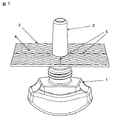
図1において、リザーバ1は、大気中に散布される揮発性液体を収納する。この液体は、多孔質芯2によってリザーバから出る。この多孔質芯のまわりに、気化表面3が取り付けられており、この表面上に一連の毛細管チャネル4が設けられている。気化表面3は、実際には4つのプレートから構成されており、これらのプレートは互いに緊密に嵌まり合い、接合線(join)5で交わり、この接合線は、毛細管チャネル4と比較して、相対的に幅が狭い。
In FIG. 1, a
気化表面のより詳細な理解は、図2を検討することによって得ることができる。ここには、気化表面を構成する、4枚の4分の1プレート6を示してある。これらは、保持プレート7に嵌まり、この保持プレートには、芯2の装着を可能にする、中心穴8がある。芯2と接触する4分の1プレート6の部分は、4分の1プレート上の毛細管チャネルが、芯と液体伝達接触するように、芯のまわりに十分緊密に嵌まるように成形されている。この態様において、個々の4分の1プレートの毛細管チャネルは、互いに平行であり、各4分の1プレートの中心半径は、芯の半径である。このように4枚は、「ヘリンボン」パターンを形成する。4分の1プレート6間の接合線5は、副毛細管チャネルを形成し、これらは、液体を芯と直接的に接触していない主チャネルに移送する。さらに、保持プレートの縁辺と4分の1プレートとが対向する場所で形成される間隙が、副チャネルとしても作用し、液体を移送する。したがって、液体を、気化表面全体にわたって散布することができる。
A more detailed understanding of the vaporized surface can be obtained by examining FIG. Here, four
図3に示す態様は、揮発性液体10を収納する、リザーバ9を含む。リザーバの首部11には、ストッパー12が取り付けられている。このストッパーを、全体的に13で示す、気化表面および伝達部材が通過する。リザーバからそれを通して液体を抽出する、伝達部材14は、毛細管チャネル15を有する、平坦毛細管部材14である。伝達部材は、平坦面状気化表面16中に延びている。この気化表面は、伝達部材14の毛細管チャネル15の連続部を含むだけでなく、それらのチャネルに平行な追加の毛細管チャネル17も含む。この場合には、気化表面は、(任意所望の機能的または装飾的形状とすることができるが)正方形であり、それには、追加で対角方向に延びる、毛細管チャネル15、17よりも小さい副チャネル18が設けられており、これらの副チャネルによって、液体と直接的に接触していない毛細管チャネルを含む、すべての毛細管チャネルに液体が流れ込むことが可能となる。
The embodiment shown in FIG. 3 includes a reservoir 9 that contains a
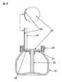
図4の態様においては、液体は、液体伝達部材から副チャネルを用いて伝達される。リザーバ19には、開放首部の全体にわたって延びる平面クロージャ21を備える、キャップ20が取り付けられている。このクロージャの穴を通過して、円筒形・円柱形芯22が取り付けられており、この芯が平面拡散部材23につながっている。芯は、リザーバの底に置かれて、平面拡散部材が平面クロージャの上に載らずに、そのわずか上で支持して、それによって2者の間に副毛細管チャネル26が画定されるようにされている。平面拡散部材24の直径は、キャップ20の内径よりも小さく、拡散部材の縁辺のまわりに環状空隙が残されている。この中に、その外向きの面に主毛細管チャネル25を保持する、曲面プレート24が取り付けられている。
In the embodiment of FIG. 4, the liquid is transmitted from the liquid transmission member using the secondary channel. Mounted on the
作動において、液体はリザーバから芯22を介して副毛細管チャネル26へと移動する。液体は、主毛細管チャネル25の端部に到達するまで、このチャネルに沿って移動する。次いで、液体は、これらのチャネルを上昇して、大気中へと気化する。
In operation, liquid travels from the reservoir through the
Claims (10)
リザーバから伝達手段によって、それと液体伝達接触している気化表面に液体を移送することを含み、この気化表面は主毛細管チャネルを含み、これらの主毛細管チャネルの少なくともいくつかに、少なくとも1つの副毛細管チャネルが交差しており、この副毛細管チャネルの横断面積は、主チャネルのそれよりも実質的に小さく、それによって液体が主チャネルおよび副チャネルの両方に流れるようする、前記方法。 A method of spraying a volatile liquid from the vaporized surface into the atmosphere by vaporization,
Transferring liquid from the reservoir by means of transmission to a vaporizing surface in liquid communication contact therewith, the vaporizing surface comprising main capillary channels, at least some of these main capillary channels including at least one secondary capillary The method wherein the channels intersect and the cross-sectional area of the secondary capillary channel is substantially smaller than that of the main channel, thereby allowing liquid to flow in both the main and secondary channels.
Applications Claiming Priority (2)
| Application Number | Priority Date | Filing Date | Title |
|---|---|---|---|
| GBGB0320461.7A GB0320461D0 (en) | 2003-09-02 | 2003-09-02 | Device |
| PCT/CH2004/000526 WO2005021052A1 (en) | 2003-09-02 | 2004-08-20 | Volatile liquid disseminating device |
Publications (2)
| Publication Number | Publication Date |
|---|---|
| JP2007504175A true JP2007504175A (en) | 2007-03-01 |
| JP2007504175A5 JP2007504175A5 (en) | 2007-09-13 |
Family
ID=28686719
Family Applications (1)
| Application Number | Title | Priority Date | Filing Date |
|---|---|---|---|
| JP2006525021A Withdrawn JP2007504175A (en) | 2003-09-02 | 2004-08-20 | Volatile liquid sprayer |
Country Status (10)
| Country | Link |
|---|---|
| US (1) | US20080203185A1 (en) |
| EP (1) | EP1660139A1 (en) |
| JP (1) | JP2007504175A (en) |
| KR (1) | KR20060119917A (en) |
| CN (1) | CN100486647C (en) |
| AU (1) | AU2004267895A1 (en) |
| CA (1) | CA2534000A1 (en) |
| GB (1) | GB0320461D0 (en) |
| MX (1) | MXPA06002096A (en) |
| WO (1) | WO2005021052A1 (en) |
Cited By (1)
| Publication number | Priority date | Publication date | Assignee | Title |
|---|---|---|---|---|
| JP2009194246A (en) * | 2008-02-15 | 2009-08-27 | Tokyo Electron Ltd | Vaporizer, substrate processing apparatus, substrate processing method, and storage medium |
Families Citing this family (9)
| Publication number | Priority date | Publication date | Assignee | Title |
|---|---|---|---|---|
| GB0306449D0 (en) * | 2003-03-21 | 2003-04-23 | Givaudan Sa | Device |
| EP1849485A1 (en) * | 2006-04-26 | 2007-10-31 | Boehringer Ingelheim microParts GmbH | Discharge device and method for evaporating a liquid and evaporator |
| US20130206107A1 (en) * | 2010-07-02 | 2013-08-15 | American Performance Technologies, Llc | Carburetor and methods therefor |
| GB201015168D0 (en) * | 2010-09-10 | 2010-10-27 | Slade Brian P | Volatile material dispenser, and dispensing screen thereof |
| JP5934161B2 (en) * | 2013-09-09 | 2016-06-15 | 武蔵エンジニアリング株式会社 | Nozzle and liquid material discharge apparatus including the nozzle |
| CN105536020B (en) * | 2015-12-02 | 2018-05-11 | 邹栋 | Disseminate volatile liquid into the dispensing device in air |
| WO2017215728A1 (en) | 2016-06-16 | 2017-12-21 | Ctr, Lda | Device for dispensing, in particular for vaporizing, volatile substances, in particular fragrances and/or active agents |
| WO2019104396A1 (en) * | 2017-11-30 | 2019-06-06 | Jim Hannon-Tan Design Pty Ltd | Apparatus for decoration and use thereof |
| KR102119933B1 (en) * | 2018-03-15 | 2020-06-05 | 최순극 | Aromatic case |
Family Cites Families (11)
| Publication number | Priority date | Publication date | Assignee | Title |
|---|---|---|---|---|
| FR2522270B1 (en) * | 1982-02-26 | 1986-10-24 | Berger Produits | DEVICE FOR ATMOSPHERIC DIFFUSION OF A PRODUCT |
| US5121881A (en) * | 1991-01-04 | 1992-06-16 | Reckitt & Colman Inc. | Air-freshening liquid container |
| US5534229A (en) * | 1992-09-16 | 1996-07-09 | Nomura & Shibatani | Volatilization suppressing agent |
| WO1998016262A1 (en) * | 1996-10-16 | 1998-04-23 | S.C. Johnson & Son, Inc. | Air freshener device with dispensing actuator feature |
| US5875968A (en) * | 1997-07-18 | 1999-03-02 | S. C. Johnson & Son, Inc. | Liquid air freshener dispenser device with nonporous capillary wicking function |
| DE19912217C2 (en) * | 1999-01-12 | 2002-09-05 | Jeyes Deutschland Gmbh | Device for dispensing active substances in the flushing water, especially in toilet bowls |
| DE29903663U1 (en) * | 1999-03-01 | 1999-06-02 | Voit Hans | Device for dispensing fragrances |
| EP1088562A1 (en) * | 1999-09-29 | 2001-04-04 | Givaudan SA | A device for the controllable transfer of a liquid and an apparatus for dispensing transferred liquids |
| GB0025887D0 (en) * | 2000-10-23 | 2000-12-06 | Reckitt Benckiser Uk Ltd | A device |
| DE20215129U1 (en) * | 2002-10-01 | 2003-03-13 | Skot S A Chemical Products Att | Device for dispensing a liquid active substance |
| US6899280B2 (en) * | 2002-10-08 | 2005-05-31 | S. C. Johnson & Son, Inc. | Wick-based delivery system with wick having sections of varying porosities |
-
2003
- 2003-09-02 GB GBGB0320461.7A patent/GB0320461D0/en not_active Ceased
-
2004
- 2004-08-20 MX MXPA06002096A patent/MXPA06002096A/en not_active Application Discontinuation
- 2004-08-20 US US10/570,039 patent/US20080203185A1/en not_active Abandoned
- 2004-08-20 EP EP04738158A patent/EP1660139A1/en not_active Withdrawn
- 2004-08-20 AU AU2004267895A patent/AU2004267895A1/en not_active Abandoned
- 2004-08-20 JP JP2006525021A patent/JP2007504175A/en not_active Withdrawn
- 2004-08-20 WO PCT/CH2004/000526 patent/WO2005021052A1/en active Application Filing
- 2004-08-20 CN CNB2004800251752A patent/CN100486647C/en not_active Expired - Fee Related
- 2004-08-20 KR KR1020067004273A patent/KR20060119917A/en not_active Application Discontinuation
- 2004-08-20 CA CA002534000A patent/CA2534000A1/en not_active Abandoned
Cited By (1)
| Publication number | Priority date | Publication date | Assignee | Title |
|---|---|---|---|---|
| JP2009194246A (en) * | 2008-02-15 | 2009-08-27 | Tokyo Electron Ltd | Vaporizer, substrate processing apparatus, substrate processing method, and storage medium |
Also Published As
| Publication number | Publication date |
|---|---|
| GB0320461D0 (en) | 2003-10-01 |
| EP1660139A1 (en) | 2006-05-31 |
| KR20060119917A (en) | 2006-11-24 |
| WO2005021052A1 (en) | 2005-03-10 |
| MXPA06002096A (en) | 2006-05-19 |
| US20080203185A1 (en) | 2008-08-28 |
| CN1845759A (en) | 2006-10-11 |
| CA2534000A1 (en) | 2005-03-10 |
| CN100486647C (en) | 2009-05-13 |
| AU2004267895A1 (en) | 2005-03-10 |
Similar Documents
| Publication | Publication Date | Title |
|---|---|---|
| US7055764B1 (en) | Two-phase evaporator device | |
| EP1613362B1 (en) | Device for dispensing a volatile liquid using a wick in an ambient air stream | |
| JP2007504175A (en) | Volatile liquid sprayer | |
| AU772055B2 (en) | Electrical device for evaporating a volatile liquid | |
| JP4879731B2 (en) | Vapor diffusion device | |
| JP2008538939A (en) | Volatile liquid sprayer | |
| US7324744B2 (en) | Multi-orientation low profile dual outlet volatile dispenser | |
| CA2591604C (en) | Two-phase evaporator device | |
| US8329477B2 (en) | Method and system for controllably releasing solutions | |
| KR20130083300A (en) | Supporting device for volatilization perfume stick and perfume bottle having herewith | |
| EP1796743B1 (en) | Fragrance dispensing device | |
| CA2840292A1 (en) | Devices and methods for emanating liquids | |
| CN207305886U (en) | A kind of split type repellent | |
| KR20060119916A (en) | Volatile liquid disseminating apparatus | |
| JP4409027B2 (en) | Air freshener storage container and fragrance diffuser | |
| AU2385699A (en) | Fluid delivery device | |
| JPS5937252Y2 (en) | aroma device | |
| KR20010045410A (en) | Wall block set for planting | |
| JPH0370400U (en) |
Legal Events
| Date | Code | Title | Description |
|---|---|---|---|
| A521 | Written amendment |
Free format text: JAPANESE INTERMEDIATE CODE: A523 Effective date: 20070713 |
|
| A621 | Written request for application examination |
Free format text: JAPANESE INTERMEDIATE CODE: A621 Effective date: 20070713 |
|
| A761 | Written withdrawal of application |
Free format text: JAPANESE INTERMEDIATE CODE: A761 Effective date: 20090728 |