JP2007500541A - Otoscope - Google Patents
Otoscope Download PDFInfo
- Publication number
- JP2007500541A JP2007500541A JP2006521965A JP2006521965A JP2007500541A JP 2007500541 A JP2007500541 A JP 2007500541A JP 2006521965 A JP2006521965 A JP 2006521965A JP 2006521965 A JP2006521965 A JP 2006521965A JP 2007500541 A JP2007500541 A JP 2007500541A
- Authority
- JP
- Japan
- Prior art keywords
- otoscope
- distal
- observation means
- instrument head
- imaging lens
- Prior art date
- Legal status (The legal status is an assumption and is not a legal conclusion. Google has not performed a legal analysis and makes no representation as to the accuracy of the status listed.)
- Pending
Links
Images


Classifications
-
- A—HUMAN NECESSITIES
- A61—MEDICAL OR VETERINARY SCIENCE; HYGIENE
- A61B—DIAGNOSIS; SURGERY; IDENTIFICATION
- A61B1/00—Instruments for performing medical examinations of the interior of cavities or tubes of the body by visual or photographical inspection, e.g. endoscopes; Illuminating arrangements therefor
- A61B1/00163—Optical arrangements
- A61B1/00188—Optical arrangements with focusing or zooming features
-
- A—HUMAN NECESSITIES
- A61—MEDICAL OR VETERINARY SCIENCE; HYGIENE
- A61B—DIAGNOSIS; SURGERY; IDENTIFICATION
- A61B1/00—Instruments for performing medical examinations of the interior of cavities or tubes of the body by visual or photographical inspection, e.g. endoscopes; Illuminating arrangements therefor
- A61B1/227—Instruments for performing medical examinations of the interior of cavities or tubes of the body by visual or photographical inspection, e.g. endoscopes; Illuminating arrangements therefor for ears, i.e. otoscopes
- A61B1/2275—Instruments for performing medical examinations of the interior of cavities or tubes of the body by visual or photographical inspection, e.g. endoscopes; Illuminating arrangements therefor for ears, i.e. otoscopes with controlled air pressure
Landscapes
- Health & Medical Sciences (AREA)
- Life Sciences & Earth Sciences (AREA)
- Surgery (AREA)
- Biomedical Technology (AREA)
- Medical Informatics (AREA)
- Optics & Photonics (AREA)
- Pathology (AREA)
- Radiology & Medical Imaging (AREA)
- Biophysics (AREA)
- Engineering & Computer Science (AREA)
- Physics & Mathematics (AREA)
- Heart & Thoracic Surgery (AREA)
- Nuclear Medicine, Radiotherapy & Molecular Imaging (AREA)
- Molecular Biology (AREA)
- Animal Behavior & Ethology (AREA)
- General Health & Medical Sciences (AREA)
- Public Health (AREA)
- Veterinary Medicine (AREA)
- Endoscopes (AREA)
- Lens Barrels (AREA)
Abstract
患者の耳の検査を可能にするオトスコープは、近位端と、耳に挿入可能な遠位挿入部とを有する器具ヘッドによって特徴付けられる。このオトスコープは、器具ヘッド内に配置される撮像レンズ列を有し、各撮像レンズ列、接眼レンズ、前記遠位挿入部の遠位開口は、光軸に沿って配列される。さらに、オトスコープは、少なくとも1つの撮像レンズ列と接眼レンズに設けられる目とを、光軸に沿って選択的に連動させるフォーカス機構を有する。撮像レンズ列と接眼レンズ内の目とは、入射瞳が実質的に器具ヘッドの遠位挿入部内に位置するように光学システムを規定し、それによって、鼓膜全体を一度に使用者によって観察できるようにする。 An otoscope that allows examination of a patient's ear is characterized by an instrument head having a proximal end and a distal insert that can be inserted into the ear. The otoscope has an imaging lens array disposed in the instrument head, and each imaging lens array, the eyepiece, and the distal opening of the distal insertion portion are arranged along the optical axis. Further, the otoscope has a focus mechanism for selectively interlocking at least one imaging lens array and an eye provided on the eyepiece along the optical axis. The imaging lens array and the eye in the eyepiece define the optical system so that the entrance pupil is located substantially within the distal insertion portion of the instrument head so that the entire eardrum can be observed by the user at one time. To.
Description
本発明はオトスコープの一般的な技術分野に関連し、特に、改良され、選択的な焦点調整が可能なオトスコープ装置に関する。 The present invention relates to the general technical field of otoscopes, and more particularly to an otoscope apparatus that is improved and capable of selective focus adjustment.
オトスコープは手持ちの器具で、医療用診断器具の分野において、主に鼓膜などの患者の耳を検査する専門医又は医療提供者の間で一般に知られている。 An otoscope is a hand-held instrument that is generally known in the field of medical diagnostic instruments, mainly among specialists or health care providers who examine a patient's ear, mainly the eardrum.
典型的なオトスコープは、専門医が手で持つことができ、使い捨ての検鏡チップをオーバーライするように装着可能な、遠位の円錐台の挿入部位を持つ器具ヘッドを有する。また、使い捨ての検鏡チップは、患者の耳の穴に適正な距離だけ挿入できるように、円錐台形状に設計されることが望ましい。通常、光ファイバの巻き毛は、ユーザによる対象の視覚化を妨げないように、挿入部の先端開口に巻きついており、前記ファイバは、ハンドルまたはヘッドのネック部分内に設けられた小型の白熱ランプあるいは電球などの、収容された光源から伸びている。そして、前記ターゲット(例えば、鼓膜)は、器具ヘッドの近位端に位置しているレンズを介して観察され、該レンズは、ユーザの観察を許すように、前記挿入部の遠位チップ開口と光学的にアラインされている。しばしば、レンズは、ターゲットの映像を拡大する。 A typical otoscope has an instrument head with a distal frustoconical insertion site that can be held by a specialist and can be worn to overlay a disposable speculum tip. Further, it is desirable that the disposable spectroscopic tip is designed in a truncated cone shape so that it can be inserted into the hole of the patient's ear by an appropriate distance. Usually, the optical fiber curly hair is wrapped around the distal end opening of the insertion portion so as not to disturb the visualization of the object by the user, and the fiber is a small incandescent lamp provided in the neck portion of the handle or the head. Or it extends from a contained light source, such as a light bulb. The target (eg, tympanic membrane) is then observed through a lens located at the proximal end of the instrument head, which lens and the distal tip opening of the insert to allow viewing by the user. It is optically aligned. Often, the lens magnifies the target image.
あるいは、CCDやCMOSベースの撮像素子などの、ビデオカメラや少なくとも1つの固体撮像素子を、ターゲットを検査するためにレンズの代わりに用いることができ、処理された画像は表示のためにビデオモニタに送信される。さらに、前記器具ヘッドは、空気圧バルブの受信ポートを備えることもでき、空気吹き出し(例えば、圧空オトスコピー)を可能とする。また、これらの装置は、場合によっては、耳、外耳道に加えて、鼻、のどを検査するのに用いることができるだけでなく、一般的な照明および拡大システムに使用することもできる。 Alternatively, a video camera or at least one solid-state imager, such as a CCD or CMOS-based imager, can be used in place of the lens to inspect the target, and the processed image is sent to a video monitor for display. Sent. Furthermore, the instrument head can also be equipped with a pneumatic valve receiving port, allowing air blowing (eg, compressed air otoscopy). In addition, in some cases, these devices can be used not only for examining the nose and throat in addition to the ear and ear canal, but also for general illumination and magnification systems.
現在この分野では、必要だと考えられているものが多数ある。オトスコープの基本機能、例えば、鼓膜の視覚化を考えるとき、瞳距離に加えて、視野を増大すること、そのより大きい拡大率を与えることが表現された必要であった。瞳距離は、実際に、全視野を見るときの、装置の最近傍の目(例えば、医者の目に最も近いレンズ)と、専門医/使用者の目との間の距離として定義されている。倍率と瞳距離は相互に関係しており、過度に拡大された画像を持つことは、医者の目にとって“より近い”画像を生ずるであろう。現在のオトスコープでは、曲りくねった構造の外耳道、およびその中で使用されているレンズのために、鼓膜全体を視野の中に入れることはできない。 There are many things that are currently considered necessary in this area. When considering the basic function of an otoscope, such as the visualization of the eardrum, it was necessary to express that in addition to pupil distance, increasing the field of view, giving it a greater magnification. The pupil distance is actually defined as the distance between the nearest eye of the device (eg, the lens closest to the doctor's eye) and the specialist / user's eye when viewing the full field of view. Magnification and pupil distance are interrelated, and having an overly magnified image will result in an image that is “closer” to the physician's eyes. With current otoscopes, the entire eardrum cannot be brought into the field of view due to the tortuous ear canal and the lenses used therein.
これらの全ての改良を実現するためには、一般に、上記要因のすべては、関連しているので、視野深度のトレードオフを必要とする。例えば、視野深度が失われると、(いわゆる標準、あるいは公称の外耳道と比較して)長い、あるいは短い外耳道を持ついくらかの患者にとっては、鼓膜に焦点が合わなくなることとなる。この焦点の欠如は、顕著な不利益であり、医者の適切な治療を施す能力に重大な影響を与える。 In order to achieve all these improvements, in general, all of the above factors are related and therefore require a depth of field tradeoff. For example, loss of depth of field will cause the eardrum to become out of focus for some patients with long or short ear canals (compared to so-called standard or nominal ear canals). This lack of focus is a significant disadvantage and has a significant impact on the physician's ability to deliver proper treatment.
さらに、この分野において、広範囲にわたるオトスコープ検査の一部として、様々な診断手順を実行することができるということのニーズがある。このニーズは、清潔性を維持し二次汚染を防ぐために、装置に用いられる取り外し可能に取り付けられる使い捨て可能な検鏡チップに、増大する要求、および制約を置く。これらのタイプのオトスコープチップの特性となる要件の簡単なリストは、以下のものを含む:
i)最適視野を達成する(例えば、外耳道をまっすぐにする、明確な開口を最大にする)こと;
ii)鼓膜に光を効果的にあて、その部分が見えるように、鼓膜から戻ってくる光を集めること;
iii)空気吹き付け(例えば、圧空オストスコープ)を可能にするために、耳ばかりでなく、器具ヘッドに有効で実質的な流体密封シールを与えること;
iv)耳垢(耳の垢)のために、光学系を介して見る間、ある道具を配置し、使用することを可能にすること;
v)ディスペンサー又は道具箱への保存を容易とするよう、複数のチップをコンパクトな形に積むことを可能にすること;
vi)チップを使い捨て可能、または取り替え可能にするために、十分に費用対効果のある製造条件にすること;
vii)二次汚染を防ぐこと;
viii)多くの患者のタイプに合わせる(例えば、複数のサイズを設ける);
ix)典型的な耳への安全でない挿入のリスクを最小にすること;
x)使用する関連するオトスコープにあわせること。
Furthermore, there is a need in the field that various diagnostic procedures can be performed as part of a wide range of otoscope examinations. This need places increasing demands and constraints on the removably attached disposable spectroscopic tips used in the device to maintain cleanliness and prevent cross-contamination. A brief list of requirements that characterize these types of otoscope chips includes:
i) achieve optimal field of view (eg straighten the ear canal, maximize clear aperture);
ii) collecting light coming back from the eardrum so that the eardrum can be effectively illuminated and the part visible.
iii) to provide an effective and substantial fluid tight seal not only on the ear, but also on the instrument head to allow air blasting (eg, pneumatic oscilloscope);
iv) for earwax (earwax), allowing certain tools to be placed and used while looking through the optics;
v) allowing multiple chips to be stacked in a compact form to facilitate storage in a dispenser or toolbox;
vi) sufficiently cost-effective manufacturing conditions to make the chip disposable or replaceable;
vii) prevent secondary contamination;
viii) Adapt to many patient types (eg, provide multiple sizes);
ix) minimizing the risk of unsafe insertion into a typical ear;
x) Match the relevant otoscope used.
これら非常に広範囲にわたる要件のリストを満たすために、現在知られている任意のオトスコープチップは、上記特性のうちの1つまたは2つのみのために最適化されるか、それらのいくつかを適度に実施するものであることは明らかである。その結果、特に現在利用可能な使い捨ての検鏡チップのデザインに関して、欠点がある。
よって、本発明の一つの主要な目的は、上述の課題と、従来技術の欠陥を解決するオトスコープ装置を提供することである。 Therefore, one main object of the present invention is to provide an otoscope device that solves the above-mentioned problems and the deficiencies of the prior art.
また、本発明のもう1つの主要な目的は、最小数のオトスコープチップでもって、上述の課題に対する最適の解決を与える、少なくとも1つまたは1群のオトスコープチップを提供することである。この目的は、医師/専門医の診察室のスペースが問題となりうる場合ばかりでなく、種々の多数チップを管理するのに関連して起こる論理、あるいは他の問題(二次汚染など)において、特に重要である。 Another main object of the present invention is to provide at least one or a group of otoscope chips that provide an optimal solution to the above-mentioned problems with a minimum number of otoscope chips. This objective is particularly important not only when doctor / specialist consultation room space can be a problem, but also in the logic or other issues (such as cross-contamination) that arise in relation to managing a large number of different chips. It is.
また、本発明のさらに他の目的は、目標物のより大きい視野ばかりでなく、適切な倍率を与え、これにより、適切な作動距離から鼓膜全体を観察できるオトスコープ器具を提供することにある。 Yet another object of the present invention is to provide an otoscope instrument that provides not only a larger field of view of the target but also an appropriate magnification, thereby allowing the entire eardrum to be observed from an appropriate working distance.
また、本発明のさらに他の主要な目的は、性能や、効果について妥協することなく、医者による選択的な焦点合わせを行うことのできる、調整可能な光学システムを含む耳鼻科用器具を提供することである。 Yet another major object of the present invention is to provide an otolaryngological instrument that includes an adjustable optical system that allows selective focusing by a physician without compromising performance or effectiveness. That is.
また、本発明のさらに他の主要な目的は、特に、いくらかの患者(他えば、動き回る子供)には実用的でない状況において、焦点合せに通常必要となる時間の量を低減するために、典型的な鼓膜距離を実質的にカバーすることのできる、単一のフォーカス位置を持つオトスコープを提供することにある。 Yet another major objective of the present invention is to reduce the amount of time normally required for focusing, particularly in situations that are impractical for some patients (eg, moving children). It is an object of the present invention to provide an otoscope having a single focus position capable of substantially covering a typical eardrum distance.
また、本発明のさらに他の主要な目的は、必要であれば、デジタルオトスコープを実現するために、CCD、あるいは同等の撮像素子をも付加することができ、上述の焦点合わせ位置をとることを可能にする光学システムを持つオトスコープを提供することである。 Still another main object of the present invention is that, if necessary, a CCD or an equivalent image sensor can be added to realize a digital autoscope, and the above-mentioned focusing position is taken. It is to provide an otoscope with an optical system that makes possible.
よって、本発明の第1の好ましい特徴によれば、患者の耳の検査を可能とするオトスコープであって、
i)近位端と、耳に挿入可能な遠位軸対称挿入部とを有する器具ヘッドと、
ii)前記器具ヘッドの前記近位端に近接している観察手段と、
iii)器具ヘッド内に配置され撮像レンズ列とを備え、前記撮像レンズ列、前記観察手段、及び前記挿入部の遠位開口の各々は、それぞれ光軸に沿って並んで配列されており、
iv)少なくとも1つの前記撮像レンズ列と前記観察手段とを前記撮像レンズ列に対して光軸に沿って選択的に移動させるフォーカス機構を、備えるものを提供する。
Thus, according to a first preferred feature of the present invention, an otoscope capable of examining a patient's ear,
i) an instrument head having a proximal end and a distal axisymmetric insert insertable into the ear;
ii) observation means proximate to the proximal end of the instrument head;
iii) an imaging lens array disposed in the instrument head, wherein each of the imaging lens array, the observation means, and the distal opening of the insertion portion is arranged side by side along the optical axis,
iv) Provided with a focus mechanism that selectively moves at least one of the imaging lens array and the observation unit along the optical axis with respect to the imaging lens array.
その好ましい変形例によれば、フォーカス機構は、観察手段を撮像イメージ列に対して光軸に沿って選択的に移動させる。好ましくは、撮像レンズ列はチューブ部材内に配置され、前記フォーカス機構は、その回転が前記観察手段内に設けられるレンズ(optics)の並進運動を生じさせる回転部材を備える。オトスコープは、好ましくは、少なくとも1つの光学素子をその中に含んでいる接眼レンズである観察手段の相対位置を示すために表示手段を含んでいても良い。 According to the preferable modification, the focus mechanism selectively moves the observation unit along the optical axis with respect to the captured image sequence. Preferably, the imaging lens array is disposed in a tube member, and the focusing mechanism includes a rotating member whose rotation causes translational movement of lenses (optics) provided in the observation means. The otoscope may include display means to indicate the relative position of the observation means, which is preferably an eyepiece containing at least one optical element therein.
好ましくは、フォーカス機構は、患者の身体的特徴、観察されるべき彼/又は彼女の特徴、および/又は他の要因に依存して、医者により使用されうる好ましい焦点位置に、繰り返し設定することができ、かつ、他のフォーカス設定を行うことができる。 Preferably, the focus mechanism may be repeatedly set to a preferred focus position that can be used by the physician, depending on the patient's physical characteristics, his / her characteristics to be observed, and / or other factors. And other focus settings can be made.
例えば、接眼レンズ上に位置する回転ノブの手段によって、フォーカス機構を調整することにより、使用者はより大きい倍率と視野の両方を達成できるだけでなく、焦点位置を、対象物距離に訂正することができる。あるいは、該焦点機構は、器具ヘッドの対向する水平側面上に配置された窓を通して使用者がアクセスすることもできる回転スリーブ部材を含む。指示手段は、好ましい焦点位置を達成されたときを示すよう戻り止めをさらに含んでいてもよい。 For example, by adjusting the focus mechanism by means of a rotary knob located on the eyepiece, the user can not only achieve both greater magnification and field of view, but also correct the focus position to the object distance. it can. Alternatively, the focusing mechanism includes a rotating sleeve member that can also be accessed by the user through a window located on the opposing horizontal side of the instrument head. The indicating means may further include a detent to indicate when a preferred focus position has been achieved.
本願の撮像レンズ列と観察手段の目が光学システムを定義する。ここで説明する器具の光学システムは、実質的に器具の遠位挿入部内に位置する入射瞳を有し、従来のオトスコープより広い視野を可能にする。一つの変形例によれば、開口絞りが、システムの入射瞳と出射瞳の両方に対する接合部を形成するために、光学に対するシステム内に配列される。 The imaging lens array of this application and the eyes of the observation means define the optical system. The instrument optical system described herein has an entrance pupil located substantially within the instrument's distal insert, allowing a wider field of view than conventional otoscopes. According to one variant, an aperture stop is arranged in the system for optics in order to form a junction for both the entrance pupil and the exit pupil of the system.
本発明の別の好ましい特徴によれば、患者の耳の検査を可能にするオトスコープにおいて、前記オトスコープは、
i)近位端と、患者の耳に挿入される遠位挿入部とを有する器具ヘッドと、
ii)前記器具ヘッドの前記近位端に取りつけられた観察手段と、
iii)前記観察手段に対して遠位にある前記器具ヘッド内に配置される撮像レンズ列と、
iv)前記撮像イメージ列と、前記器具ヘッドの挿入部の遠位チップ開口に実質的に近接して配置される入射瞳孔を有する前記観察手段とからなり、前記撮像レンズ列は、画像を前記観察手段に中継し、前記撮像レンズ列は、鼓膜全体を一度に捕らえることができ、該鼓膜の画像を前記観察手段を通して中継する、ものが提供される。
According to another preferred feature of the invention, in an otoscope that allows examination of a patient's ear, the otoscope comprises:
i) an instrument head having a proximal end and a distal insert inserted into the patient's ear;
ii) observation means attached to the proximal end of the instrument head;
iii) an imaging lens array disposed in the instrument head distal to the observation means;
iv) The imaging image sequence and the observation means having an entrance pupil arranged substantially close to a distal tip opening of the insertion portion of the instrument head, wherein the imaging lens sequence is configured to observe the image. The imaging lens array is capable of capturing the entire eardrum at one time and relaying the image of the eardrum through the observation means.
また、本発明の別の好ましい特徴によれば、遠位挿入部が設けられる器具ヘッドを有するオトスコープ器具の製造方法であって、
i)前記器具ヘッドの近位端に近接する観察手段を設けるステップと、
ii)前記器具ヘッド内に配置される撮像レンズ列を設けるステップと、ここで、前記撮像レンズ列と、前記観察手段の各々と、前記挿入部の遠位開口は、光学軸に沿って、並んでおり、
iii)前記撮像レンズ列と前記観察手段との少なくとも1つを、選択的に、前記光軸に沿って、相対的に移動させるフォーカス機構を設けるステップとを含む、ものが提供テイクされる。
According to another preferred feature of the present invention, there is provided a method of manufacturing an otoscope instrument having an instrument head provided with a distal insertion portion,
i) providing an observation means proximate to the proximal end of the instrument head;
ii) providing an imaging lens array disposed in the instrument head, wherein the imaging lens array, each of the observation means, and the distal opening of the insertion section are aligned along the optical axis And
and iii) providing a focus mechanism for selectively moving at least one of the imaging lens array and the observation unit along the optical axis.
また、本発明の別の好ましい特徴によれば、
耳に挿入される遠位挿入部を有し、該遠位挿入部は遠位開口を有する器具ヘッドと、
前記器具ヘッド内に収容される光学システムであって、該光学システムは、入射瞳と、上記遠位開口をもつ光軸に沿って並んだ対象のターゲットの像を観察するための観察手段とを含み、ここで、上記入射瞳孔は、その遠位開口に近接する上記器具ヘッドの上記遠位開口に近接して位置している、ものよりなるオトスコープが提供される。
Also according to another preferred feature of the invention,
A distal insert inserted into the ear, the distal insert having an instrument head having a distal opening;
An optical system housed in the instrument head, the optical system comprising an entrance pupil and an observation means for observing an image of a target of interest aligned along the optical axis having the distal aperture. And wherein the entrance pupil is provided comprising an entrance pupil located proximate to the distal opening of the instrument head proximate its distal opening.
本発明の一つの効果は、ここで説明した器具を、医者がさらなる訓練を必要とされることなく、使用できることである。 One advantage of the present invention is that the devices described herein can be used without requiring further training by a physician.
また、本発明の別の効果は、大多数の患者によって使用される固定の焦点設定にしたがって現在の装置を利用でき、あるいは、ある要因に依存して、必要に応じて、代替的にかつ選択的にフォーカス位置を修正できることである。 Another advantage of the present invention is that the current device can be utilized according to a fixed focus setting used by the majority of patients, or alternatively and selected as needed, depending on certain factors. In other words, the focus position can be corrected.
また、本発明の別の効果は、医者が器具をパンすることなく鼓膜全体を観察でき、それにより、特に、患者の耳が感染し、痛みがあるときに、検査時間を改善し、患者に苦痛を与える検査手順を軽減することである。 Another advantage of the present invention is that the doctor can observe the entire tympanic membrane without panning the instrument, thereby improving the examination time, especially when the patient's ear is infected and painful. To reduce painful testing procedures.
本発明の器具によってさらに得られる効果は、その任意の方向において、片手の操作ができることである。 The effect further obtained by the device of the present invention is that one hand can be operated in any direction.
これら、及び他の目的、特徴、効果は、添付の図面と合わせて読まれるべきである以下の詳細な説明から容易に明らかになる。 These and other objects, features and advantages will be readily apparent from the following detailed description which should be read in conjunction with the accompanying drawings.
以下の説明は、本発明に従って製造されるオトスコープの最良の実施形態と、使い捨てで、開放可能なように装着できるオトスコープチップ要素のデザインの最良の実施形態と、に関連する。しかし、その説明から、以下に示す発明の形態を実施できる分野の技術者にとって明らかな変形例及び修正例は多数存在する。 The following description relates to the best embodiment of an otoscope manufactured according to the present invention and the best embodiment of a disposable, releasably attachable otoscope tip element design. However, there are many variations and modifications apparent to those skilled in the art that can implement the embodiments of the invention described below.
さらに、遠位、近位、頂上、底、「前部」、「後部」、右回り、左回りなどのいくつかの用語は、添付図面を参照しやすくするため、発明の説明において使用する。しかし、これらの用語は、非常に厳密な指摘を行う場合を除いて、必ずしも発明の限定を言及するものではない。 Furthermore, some terms such as distal, proximal, apex, bottom, “front”, “rear”, clockwise, counterclockwise, etc. are used in the description of the invention to facilitate reference to the accompanying drawings. However, these terms do not necessarily refer to limitations of the invention, except as very rigorously pointed out.
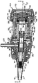
図1に示すように、符号10が付されたオトスコープは円筒形のハンドル部14を有し、ハンドル部14は、内蔵バッテリー区画(図示せず)内に保持される1組のバッテリー(図示せず)を内蔵する。ハンドル部は、バッテリー交換を可能にするために、好ましくは除去可能な底部17を有する。ハンドル部14は、器具10を手で持つことを可能にするものであり、そこに装着される器具ヘッド18を収容する大きさとされた頂部を有する。器具ヘッド18は、吹き入れポート28を収容するように実質的に中空になっており、該ヘッドは、近位端22と、その反対の、図6に示す軸対称の遠位挿入部29を持つ対向する遠位端26によって特徴づけられる。ハンドル部14は、さらに、底部17上に配置される始動ボタン23を有し、このボタンは、該装置ばかりでなく、器具ヘッド18の首またはのど部分に内蔵される照明部の照明出力を選択的に調整するレオスタット25のパワーアップを行うために用いる。注意すべきは、上述のハンドル部に関する特徴はそれぞれ、本分野では公知であり、本発明に関してさらなる説明の必要はない。
As shown in FIG. 1, the otoscope denoted by
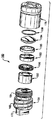
オトスコープ10の残りのより詳細な形態についてより具体的に説明する前に、図2〜図5と、器具10の遠位軸対称挿入部29上にかぶせるようにマウントされる、好ましい使い捨て検鏡チップ要素40に特に言及する。チップ要素40は、好ましくは、ポリプロピレンのような鋳造可能なプラスチック素材で製作され、一対の開口端、すなわち、より幅広の近位端48に対して外側に先細りになる幅の狭い遠位端44を有する実質的に軸対称の形状によって定義される。近位端22はまた、いくつかの非軸対称の特徴を有しており、以下、詳細に説明する。
Before describing the remaining more detailed forms of the
以下の説明のために、図2〜図5に示されるチップ要素40は、大人用サイズのチップ、すなわち、大人の患者の耳に挿入されるチップを表している。しかし、各チップは、対象となる患者に関係なく、チップ要素40を、オトスコープに、特に、図6の遠位軸称挿入部29に装着できるように、外側と内側の両方に、いくつかのはめ込み構造を通常有する。チップが、患者によって大きさを変えることができるようつくられるのは容易に理解できるであろう。
For purposes of the following discussion, the
上述の内容に加えて、本願のチップ要素40はそれぞれ、大きな遠位開口を有し、任意の以前公知の、その開口サイズの使い捨てのチップ要素により、患者の外耳道内へより大きい距離をここちよく伸ばすことができる。
In addition to the foregoing, each
図15を参照して、代表的なチップ要素は、外耳道の生体構造と、器具10の遠位軸対称挿入部29の円錐構造に基づいた、臨界寸法をもつことが実験的に決定されてきた。チップ要素40の遠位端の内径と、耳内に挿入可能なチップ要素のその部分の長さの両方を増大することにより、鼓膜に対するよりよいアクセス、及びそれのよりよい外観を得ることができる。これを説明するために、本発明に従って製造された、大人用サイズのチップ要素40と、子供用チップ要素40Aとの比較が、同じタイプの既知のチップ要素40´,40A´とともに、図15に示されるように与えられる。まず、各チップ要素40,40´,40A,40A´は一対の表面を有し;第1の表面は、各チップ要素の近位端から‐I‐で示される中間インターフェースまでの、オトスコープ10の遠位軸対称挿入部29の円錐を収容することが必要とされる表面であり;第2の円錐表面は、中間インタフェース‐I‐から遠位チップ開口まで伸びる円錐形の表面である。本願のチップ要素40,40Aはそれぞれ、実質的に中間インタフェースを超えて長くなっており、それゆえチップを患者の外耳道内へより長い距離を伸ばすことができる。さらに、各チップ要素40、40Aの遠位チップ開口は、描かれた従来のチップデザイン40´,40A´と比較して広くなっている。それぞれの主な違いを、本発明に従って製造された現存するオトスコープ円錐と本発明に従って製造された挿入部の各々上に表現された、チップ要素40,40A、40´,40A´の各々のオーバレイとともに、図15において表に示されている。
Referring to FIG. 15, a representative tip element has been experimentally determined to have critical dimensions based on the anatomy of the ear canal and the conical structure of the distal
図2〜5に戻って、各チップ要素40は、意図された患者(例えば、子供、大人など)にかかわらず、チップ要素の近位開口端48に関係して位置される複数の外部係合特徴52を有する。この特定の実施態様によれば、3つのこのような特徴52が、周上に約120度毎に相互に等間隔に離れて設けられている、ただし、設けられる係合特徴52の実際の数は、容易に変更可能である。本実施の形態による各外部係合特徴52は、チップ要素40の開口近位端48から放射状に伸び、実質的にL型を形成する、外周固定部55とこれに依存する軸方向部54とを有し、前記外周固定部55は、その係合面上に位置する複数の歯56を有する。さらに、前記外周固定部55は、実質的にV字形状をしており、該部分は、前記依存する軸方向部54との界面で最大の厚みを有し、対向する端で、テーパーされた最小の厚みを有し、これにより、傾斜した係合表面をもっている。前記依存する軸方向部分は、複数のチップ要素40の積み重ねを可能とするばかりでなく、該チップ要素をオトスコープに装着するときのグリップ表面を与えている。前記依存する軸方向部の各々間に配置される、さらなる複数の、空間を置いた軸方向リブ66もまた、後のセクションでより詳細に記述するように、チップ要素40を装着するとき、握り表面を与える。
Returning to FIGS. 2-5, each
ここで記述したチップ要素40の内部表面60は、光透過性を向上させるために研磨され、さらに好ましくは、近位チップ開口の近くに位置した、角度の付いた内部突起64を有している。図5を参照して、前記チップ要素40はまた、内部環状シールリング70を有し、これは、チップ要素を、器具ヘッド18の遠位軸対称挿入部29の円錐部分に密封するにおいて助けとなるよう、好ましくは、吸い込みのために、設けられている。
The
図6、および7を参照して、器具ヘッド18は、遠位軸対称挿入部29上に覆いかぶさるように、かつチップ要素40の器具10への開放可能な取り付け/着脱を可能とするアクチュエータ機構にマウントされる、上述した使い捨てチップ要素40を含む、いくつかの要素を保持している。
With reference to FIGS. 6 and 7, the
上述の器具10は、知られているように、図7に部分的に示されている、ホース結合272を介して、図7の吹き入れポート28への圧空オトスコピーに用いることができ、該ホース結合は、よく知られている空気供給源(図示せず)まで伸びている。
The
器具ヘッド18の制限の中で、かつ、遠位軸対称挿入部で始まり、定義された光学軸27に沿って近位に延びるものは、所定個数の光学要素を含む撮像列であり、そのほとんどは、開口端の筒状部材80内に配置されている。該チューブ部材80は、ここで3つの軸セクションで定義される可変の直径を有し、各軸セクションは、異なる内径を持っている。チューブ部材80の第1の軸セクション84は、その遠位端での内径により定義されており、その末端の頭の内径によって定義され、対象の末端、または、それぞれが重なるように隣接するような関係で配置されるレンズ96とレンズ100を保持するための大きさを有する。レンズ96とレンズ100は、互いに近接するように設けられ、対象遠位レンズ96は、チューブ部材80の末端の最も大きい開口部から部分的に伸張する。本実施の形態によれば、チューブ部88の第2の軸区間は、第1の軸区間の直径より大きな内径を有することを特徴とし、第2の軸区間は、それぞれが適切な間隔で配置されている第1の中継レンズ104と、開口絞り98と、第2の中継レンズ112とを有する第3の軸区間に接続している。チューブ部材80の第3の軸区間の直径は、第1の軸区間84、及び第2の軸区間88の直径より大きい。撮像列の機能と、ここで述べた形態10の光学システム全体の機能は後半で論じる。
Within the limitations of the
器具10の全体アセンブリに戻って、チューブ部材80は、それも、器具ヘッド18内に位置している内部前方アセンブリ116内に保持され、ここで、チューブ部材80の第1の軸部84は、遠位軸対称挿入部29内に適合する大きさとなっている。内部前方アセンブリ116は、チューブ部材80に対する支持を与えており、さらに、照明アセンブリ124から伸びる複数の光ファイバ(図示せず)のための手段を与えている。図6を参照して、照明アセンブリ124は、器具ヘッド18の首の、あるいは、のど部分内に適合し、該照明アセンブリは、小型の白熱灯128を有し、該白熱灯は、ベース136内にマウントされて、ランプ保持器140を介してそれに接続され、上記の各々は、円筒状スリーブ部材144内に、保持されている。バンパーガード146は、レンズエンベロープを保護するために、白熱灯128の頂部上に配置されている。照明アセンブリの、図1のハンドル部14内に設けられるバッテリ(図示せず)との電気的接続と、図1のレオスタット25への相互接続とは、一般的に知られており、本発明の本質部分を構成するものではない。
Returning to the overall assembly of the
好ましくは、チューブ部材80の第1の軸部84は、図6に示されるように、遠位対物レンズ96が遠位の開口部に近位するように遠位軸対称挿入部29の内部に適合され、チューブ部材と周囲の内部前方組立部116は、これらを収容する大きさの器具ヘッド内部における開口を通って配置される。好ましくは、該チューブ部材80は、適切な接着剤を用いて、内部前方アセンブリ116の近位端に密封され、そこで第3の軸セクション92の一部がそこから伸びている。図7で150として示されるシールは、図7に部分的に示される、ホース接合部272などを介して、空気供給部に対して空気の吹き入れが行われるように、吹き入れポート28に近接して(例えば、後ろにて)いなければならない。言い換えると、吹き入れポートに入る空気は、前方に(例えば、挿入部および遠位チップに向かって)流れるものであり、シールが、吹入ポートを超えて近位端に向かっていなければならないことを意味する。
Preferably, the
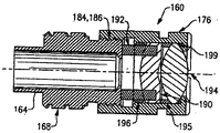
図6、7、13、14により具体的に示されるように、接眼レンズ機構160は、器具ヘッド18の近位端48に保持され、該機構は、その矩形の遠位端172に近接して配置された1組の外部ネジ168を持つ実質的に円筒形のレンズキャリア部材164を含む。該レンズキャリア部材164の矩形遠位端172は、図7の対応する開口180に適合する大きさであり、レンズキャリア部材164を保持し、該部材が回転運動するのを防ぐ器具ヘッド内部に設けられている。チューブ状のレンズ保持部材176は、該レンズ保持部材の内側の遠位端、および上記レンズキャリア部材164の近位端の外側、上にそれぞれある、対応するネジ部186、184により、上記レンズキャリア部材164にしっかりと固定される。該レンズ保持部材176は、一対の光学レンズ190、194を受け入れる大きさであり、レンズ保持部材とレンズキャリア部材とが器具ヘッドに組み立てられるとき、図7の光軸27に沿って配列され、その上に、撮像列の光学要素96、100、104、112も並んで配置される内部を、含んでいる。接眼レンズ機構160は、さらに、それぞれ、レンズ190とレンズキャリア部材164との間に配置される、波スプリング192と、レンズ保持材196とを含む。さらに、スペーサ195は、レンズ194、190の間に配置され、Oリング199は、レンズ194をレンズキャリア部材176で密封するために使われる。
As shown more specifically in FIGS. 6, 7, 13, and 14, the
図6、7、及び12を参照して、レンズキャリア部材164の外部スレッド168は、その上に横たわる関係でその上に適合される円筒状のフォーカシングスリーブ部材200の内表面上に設けられた1組の対応するスレッド207と係合する。フォーカシングスリーブ部材200は、該スリーブ部材が取り付けられたとき、器具ヘッド18の近位端48から突出するように伸びる軸方向長さを有する。柔らかい握持可能なエラストマーカバー202は、スリーブ部材200の軸部を覆い、該カバーは、突起203によって決定される移行の端までスリーブ部材とともに回転するようにマウントされている。図7にのみに示される、ボール204、および圧縮スプリング206は、それぞれ、器具ヘッド18の内部内に配置され、各々は、フォーカシングスリーブ部材200の外側上に形成されている単一のくぼみ(図示せず)に並んでおり、該スプリングは、ボールにバイアスをかけ、予めメーカで設定されたフォーカス位置に到達したことを使用者に知らせる回転止めを形成している。フォーカシングノブ208は、フォーカシングスリーブ部材200の近位端に取り付けられた留め具である。フォーカシングノブ208は、中央開口212を有し、フォーカシングスリーブ部材200、およびレンズ保持部材176の各々が、それぞれするように、位置合わせした光軸27に沿って対象物を、使用者/医者が観察できるようにし、かつ、図13の接眼レンズ機構160の、スリーブ200の回転運動を介しての撮像列に対する、選択的な軸調整を可能にする。好ましくは、および、組立の間に、レンズ保持部材176は、レンズキャリア部材164に対して調整される。この調整は、例えば、ある焦点長さを有する人々に対する工場設定、および、より長いデフォルトの焦点位置を有する獣医使用のための異なる工場設定を可能にするものであり、ここで、該スリーブ位置は、単に、この位置の上か、下かを、調節する。
With reference to FIGS. 6, 7, and 12, the
調節可能性の目的のために、器具ヘッド18は、さらに図8、図9に示す一対の窓21を有し、これらは、その対向する水平サイド上に形成されており、ここで、スリーブ部材200に対する柔らかい把持可能なエラストマーカバー202の軸方向部は、例えば、図8,9に示すように、フォーカスノブ208に加えて使用者がアクセスしやすいようになっている。
For the purpose of adjustability, the
器具10のチップアクチュエータ機構を、図2〜5、図10、図11、図18(a)、図18(b)を参照して、詳細に説明する。このメカニズムは、器具ヘッド18の遠位端に安定的に装着されるチップ要素保持材部材240を含み、該保持材は、複数の周状的に間隔を置いて配置されたスロット242を含む。本実施の形態においては、3つのスロット242が設けられ、そこにおいて、該スロットのうちの2つは、周状の傾斜した2つの表面244を有する。傾斜した表面244の各々は、チップ要素40の外部係合タブ52上に設けられた歯56と噛合するための1組の歯を有する。前記チップアクチュエータ機構はさらに、スプリング256の手段によってバイアスされる、回転可能なアクチュエータノブ252を含み、該スプリングは、アクチュエータノブ252におけるスロット264を通って、保持部材240内に設けられた穴268に至る軸方向第1末端260を有する。スプリング256の残っている末端269は、アクチュエータノブ252上に形成されているスロット270内に適合した。保持部材240は、回転可能なアクチュエータノブ252の前方対向表面に取りついており、該アクチュエータノブはさらに、前記前方対向表面から、周状の傾斜している表面244を持たない、保持部材内のスロット242内に伸びるピン254を含む。
The chip actuator mechanism of the
動作において、上記したようなオトスコープチップ要素40は、器具ヘッド18の遠位端上に、より詳しくは、遠位軸対称挿入部29にオーバーレイする関係で、取り付けられ、外部係合特徴52の各々の、周状確実化部55は、チップ要素保持部材240内に設けられた周状スロット242内に適合している。チップ要素40は、その後、チップ要素保持部材240の対応する傾斜面244を持つウェッジ状の係合特徴の2つの歯56と係合するよう、この例では、時計方向にねじられ、これにより、正の係合を与えるとともに、かつ、該チップ要素40を器具10に装着するときに、使用者に対して感触の良い手触りを提供する。
In operation, the
図10、11、18(a)、及び18(b)を参照して、患者の検査の後に、チップ要素40を器具10から開放するために、アクチュエータノブ252を、好ましくは、アクチュエータノブ252の外表面上に配置されたインジケータ261により示される反時計周り方向に、回転する。これは、固定的なチップ要素保持部材240に対するノブ252の回転運動を生じ、 さらに、前面対向ピン254が、傾斜面244を持たないそのスロット242を移動させ、チップ要素40を保持部材240のスロットから回転敵に駆動し、該チップ要素を開放する。
Referring to FIGS. 10, 11, 18 (a), and 18 (b), to release the
ここで説明するチップ要素40の設計は、かなり普遍的である;すなわち、該チップ要素は、ここで記述した器具10に適合するだけでなく、多くのすでに存在する、米国特許公報3,698,387号に記載されたバイオネット型取り付け方法や、米国特許公報4,366,811号に記載される、排出型機構を用いたもののような、多くの既に存在しているオトスコープに適合するように設計されており、上記特許の各々の全内容は、参照によりここに取り込まれる。
The design of the
動作において、焦点機構の使用は、接眼レンズ機構160のレンズ(optics)の、器具10の撮像列に対する、相対的な移動を許す。フォーカシングスリーブ部材200と、柔らかい把持可能なエストラマカバー片202は、おのおの光軸27の周りに回転することを許し、一方、レンズキャリア部材164と、取り付けられたレンズ保持部材176は、器具ヘッド18との回転可能に固定した接続により線形に移動可能にのみなされている。チューブ部材80内に配置された、前方対物レンズ96を含む、前記光学撮像列の残りの部分は、静止状態にあり、それゆえ、回転運動が達成され、フォーカス調整を行うことを可能にする。上記したように、ボールの、フォーカシングスリーブ部材200のくぼみ内への、圧縮ばねによりバイアスされた係合は、使用者/医者により感じられる、所定の固定された焦点位置(プリセットされた位置、または、接眼レンズとチューブ部材80内の静止した撮像列の残りの光学素子との間の距離)を示すこととなる。
In operation, the use of the focus mechanism allows the optics of the
このプリセット、または他のフォーカス位置を示すことは、把持可能なエラストマーカバー202の外側上に設けられた、視覚表示器209の手段によって達成され、該カバーの部分は、フォーカスノブ208の代わりに、柔らかい把持可能なカバー202によってフォーカシング機構の選択的な回転運動を可能するよう、器具ヘッド18の水平側面上に形成された窓21を介して、アクセス可能である。
Indicating this preset, or other focus position, is accomplished by means of a
マーカー213の目盛りは、戻り止めと結合して、さらに器具10の好ましい公称焦点位置を示す視覚表示器209と並んで配置することのできるプリセットフォーカス位置マーカー215を含む窓21に近接する器具ヘッドのエッジ部分上に、形成されている。
The scale of the
本実施の形態による、所定の固定された焦点位置においては、撮像システム全体の全長(すなわち、接眼レンズ光学素子を含む最も遠位と最も近位の光学表面の間の距離)は、訳77.60mmであり、倍率は、鼓膜が、検鏡チップ要素40の開口遠位端44から約10mmの作動距離に位置しているとき、1.63Xであり、被写界深度は、約3〜5mmである。さらに、公称瞳距離は約21.5mmである。
For a given fixed focal position according to this embodiment, the total length of the entire imaging system (ie, the distance between the most distal and most proximal optical surface including the eyepiece optics) is 77. 60 mm, the magnification is 1.63X when the eardrum is located at a working distance of about 10 mm from the open
図7、図19を参照して、開口絞り108は全光学システムの入射瞳8と出射瞳9の両方に光学的に接合している。軸位置と入射瞳8の大きさは、図19に6として図式的に示されるように、鼓膜全体の遮られることのない眺望を達成するにおいて臨界的である。もし、レンズ96に対して離れて位置する入射瞳8が該レンズに近過ぎる場合、チップ要素40の端によって鼓膜6の上縁から出射する光線の過剰な遮りを生ずる。もし、出射瞳がレンズ96からはるかに遠く離れて位置する場合、今度は、レンズ96とレンズ100とからなる二重物の最初、又は最後の光学面の端によって、鼓膜6の上縁から出社する光線の過剰な遮りを生ずる。本実施の形態において、出射瞳8は、光線の遮りが最小である、鼓膜6の最適な眺望を達成するよう、対物レンズの二重物(レンズ96とレンズ100)に近接して位置いている。同様の考慮が、開口絞り108の物理的な大きさにも当てはまる。
7 and 19, the
出射瞳9は、レンズ194の最も近接して光学面に対して約21.5mmの近接位置に位置している。この距離は、a)耳検査の間における使用者の眼の水平動きに関連する最適な映像の安定性、b)最小の光線遮りを持つ、鼓膜6の最適な眺望を得ること、および、c)大きい範囲にわたる光学レンズを収容する能力、を与える。この、レンズ190と194に対する出射瞳の位置は、フォーカシング機構の位置に関係なく、一定である。
The exit pupil 9 is located closest to the
ここで説明した光学システムは、図20に示されるように、オトスコープの近位端上に電子撮像アセンブリ304を追加することによって、ビデオ/撮像素子人間オトスコピーに容易に拡張することができる。さらに、ここで説明した装置は、同様に、光学またはビテオ/撮像素子をベースとして獣医オトスコピーのために同様に使用することができる。さらに、適切な光学アダプターを用いることにより、例えば、先行する実施形態において示される観察手段に光学素子を追加することによって、容易に、かつ都合良く、ここに示した光学システムを修正することができる。
The optical system described herein can be easily extended to video / imager human otoscopy by adding an
接眼レンズ機構のレンズ190および194の選択的な焦点合わせのための移動は、使用者に、クローズアップヴュー(幼児の耳検査において重要)と、遠位ヴュー(のどと鼻の検査において重要)を与えるものである。鼓膜6と、遠位レンズ96の第1の光学表面間の作動距離は、本実施の形態によれば、27mmあたりになるように、最適化される;この後者の寸法は、それは、落とすコープを外耳道内に深すぎるまで挿入する間において、正確な設定を与えるので、臨床上重要である。さらに、ここで説明した光学システムは、眺望手段において使用者に鼓膜の正像を生成する。
Movement for selective focusing of the
撮像列は、検査時に、実質的に対物複レンズ96、100を耳内に置く。なぜなら、この光学要素は、器具ヘッド18の最も遠位の部分に位置し、いかなる代表的なオトスコープより、より近接しているからである。その結果、より大きい(すなわち、より広い)視野が達成される、すなわち、鼓膜の面積よりより大きい面積を、使用者が装置の操作位置において観察することができる。さらに、入射瞳の位置は、約27mmの、あるいはそれ以上の作動距離に対して、一般的な大人の鼓膜の遮りのない眺望を可能とし、ここで、前記作動距離は、鼓膜をレンズ96の遠位面から分ける空間として、あるいは、本実施の形態によれば、鼓膜からチップ要素40の遠位端までの約9.5mmである。ここで説明した光学システムを用いて、約33mmの作動距離で、約9mmより大きい視野を創ることにより、器具10をカメラをぐるっと回して撮影することなく、鼓膜全体を観察することができる。チューブ部材80内に収容される光学素子と、接眼レンズ光学素子190、194との間の分離は、作動距離の適切な範囲内での焦点合わせを可能にすることと、使用者の使いやすさのために補償をすることを許すよう、可変である。以上の結果、倍率、視野、作動距離、瞳距離、およびフォーカス範囲の間の適切なトレードオフが達成される。後者のパラメーターは、装置を、さらに、例えば、患者ののどや鼻の検査に使用することができるよう、付加的に臨界的であるものである。
The imaging column substantially places the
オトスコープに関連する、特に、視界の主線内に位置する光学素子により撮像をするスタイルに関連する付加的な問題は、耳内に器具を挿入することが、光学素子を介して見ている間は、これをするのが大変困難である、ということである。診断用オトスコープおよびその他のものは、拡大窓を側部に、あるいは道の外に移動することを可能にするが、しかしその結果得られる眺望は、代表的にきわめて障害が起きたものであり、制限された領域を通してキューレットを使用することは理想からはほど遠い。 An additional problem associated with otoscopes, particularly with respect to the style of imaging with optical elements located within the main line of sight, is the insertion of an instrument in the ear while looking through the optical elements. Is that it is very difficult to do this. Diagnostic otoscopes and others allow the magnifying window to move to the side or out of the way, but the resulting view is typically highly disturbed. Using a curette through a limited area is far from ideal.
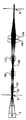
図16を参照して、上記の問題を取り扱うものとして、装着チップ280と、キューレット284は、以下に説明するが、これは例えば、上述したようにオトスコープ10の光学素子を通って観察をしている間に、実質的によりよい器具の挿入をするものである。本実施の形態による装着チップ280は、基本的には、患者に接するチップをオトスコープから伸び出させ、キューレット284が挿入され、操作され得る大きな開放領域を残すようにするカゴ様の部材290である。患者に接するチップが、種々の形状、および大きさを取ることができることは、カゴの距離、支持構造がそうすることができることから、理解できるであろう。本実施の形態においては、カゴ様部材は、遠位の耳挿入部298と近位のオトスコープ装着部299との間に伸びる3つの脚294によって定義され、該カゴ様部材の全体は、約1インチの長さである。キューレット284は、上記脚94の間の上記定義された開放領域内でそれを操作する能力を最大化するよう理想的にカーブされている。一部または全部のカゴが、再使用可能である、あるいは一体的に取付けられる場合の代替的な形状、およびその範囲は、本分野の当業者によって容易に明らかであろう。しかしながら、完全な使い捨て可能なバージョンの利点は、装置化の特性が、露出、および二次汚染のリスクを増す何らかの異物が耳から除去されることを、含むことである。チップおよびオトスコープ光学素子の長さは、チップの前面にある領域が装置の使用に焦点が合うように、整合していなければならないことに注意すべきである。オトスコープ装着部299は、図2〜5に示されるように、外部係合特徴を含むことが好ましく、あるいは、そこで使用されるオトスコープのチップ装着機構に依存して、内部フード取り付け爪を持つことが好ましい。
Referring to FIG. 16, the mounting
図17を参照して、使い捨てのオトスコープチップにあるさらなる問題は、それらが大多数の患者の耳をうまくシールできないことにある。さらに、柔らかいオーバーモールドチップのバージョンは、比較的よくシールするが、しかし、高分子弾性体が耳と干渉する深さを超えて、耳内に挿入することを妨げてしまう。したがって、チップは効果的なシールを達成するが、空気の吹き入れの間に、本質的である視覚化を、妨げる、あるいは邪魔をする。もし、鼓膜が、この処理の間に見ることができなければ、動き(あるいは、その欠如)が診断の基礎を創るので、シールすること、あるいは吹き入れをすることは、実用的な目的とはならない。 Referring to FIG. 17, a further problem with disposable otoscope tips is that they fail to seal the majority of patient ears well. In addition, the soft overmolded tip version seals relatively well, but prevents the polymeric elastic body from being inserted into the ear beyond the depth at which it interferes with the ear. Thus, the tip achieves an effective seal, but prevents or obstructs the intrinsic visualization during air blowing. If the tympanic membrane cannot be seen during this process, the movement (or lack thereof) creates the basis for diagnosis, so sealing or blowing is a practical purpose. Don't be.
上記の問題に対処するために、図2〜5で前述したもの、あるいは、実質的に円錐形の本体を有する他のバージョンのように、使い捨てのチップ要素の外側上をスライドする、エストラマーシールアクセサリー300が、1つの実施の形態によって、提供される。このエストラマーシールアクセサリー300は、患者の耳に対してよいシールを与え、かつ、チップ上でその軸位置を調整可能である。それゆえ、該チップは、“より深い”挿入、あるいは浅い挿入にセットすることができ、シールと、視覚化のための適切な挿入との両方を実現することができる。このシールアクセサリー300は、好ましくは、チップの遠位端にセットされ、医者が該チップを外耳道(図示せず)内に挿入する時に“押し込める”ほど、十分に柔軟であることが好ましい。
To address the above problems, an elastomer seal accessory that slides on the outside of a disposable tip element, such as those previously described in FIGS. 2-5 or other versions having a substantially
チップ上のマーキングと、深さ設定などの、さらなる特徴は、利点を与える。エストラマーシールアクセサリー300の形状自体も、本実施の形態においてはマッシュルーム形状をしているため、多様なサイズの外耳道をシールするために該アクセサリーをつぶすことを可能とする効果がある。このマッシュルーム形状のデザインの場合においては、これらのチップは位置変動に敏感でない、という効果がある(すなわち、該アクセサリーは、チップに沿った多くの異なる位置でのシールができる)。それゆえ、該アクセサリーの軸位置は、シールを効果的に最適化するために、チップの長さに沿って容易に変えることができる。上記エストラマーシールアクセサリーのために着想され、ここで使用されている発明概念を具体化する代替の形状が存在することは、容易に明らかであろう。
Additional features such as markings on the chip and depth setting provide advantages. Since the shape of the
Claims (36)
前記オトスコープは、
i)近位端と、耳に挿入可能な遠位挿入部とを有する器具ヘッドと、
ii)前記器具ヘッドの前記近位端に近接している観察手段と、
iii)器具ヘッド内に配置され撮像レンズ列とを備え、前記撮像レンズ列、前記観察手段、及び前記挿入部の遠位開口の各々は、それぞれ光軸に沿って並んで配列されており、
iv)前記撮像レンズ列と前記観察手段のうちの少なくとも1つを、選択的に、光軸に沿って相互に移動させるフォーカス機構を、備える、
ことを特徴とするオトスコープ。 In an otoscope that allows examination of a patient's ear,
The otoscope is
i) an instrument head having a proximal end and a distal insert insertable into the ear;
ii) observation means proximate to the proximal end of the instrument head;
iii) an imaging lens array disposed in the instrument head, wherein each of the imaging lens array, the observation means, and the distal opening of the insertion portion is arranged side by side along the optical axis,
iv) a focus mechanism that selectively moves at least one of the imaging lens array and the observation unit along the optical axis;
An otoscope characterized by that.
前記フォーカス機構は、前記撮像レンズ列に対して前記観察手段を、選択的に、光軸に沿って、移動させる、
ことを特徴とするオトスコープ。 The otoscope according to claim 1,
The focus mechanism selectively moves the observation means along the optical axis with respect to the imaging lens array;
An otoscope characterized by that.
前記撮像レンズ列は、チューブ部材内に配置され、前記フォーカス機構は回転部材を有し、前記回転部材の回転によって、前記観察手段の並進運動を引き起こす、
ことを特徴とするオトスコープ。 In the otoscope according to claim 2,
The imaging lens array is disposed in a tube member, the focus mechanism has a rotating member, and causes the translational movement of the observation means by rotation of the rotating member.
An otoscope characterized by that.
前記観察手段の相対的な位置を表示する表示手段を有する、
ことを特徴とするオトスコープ。 In the otoscope according to claim 2,
Display means for displaying a relative position of the observation means;
An otoscope characterized by that.
前記表示手段は、フォーカス機構が好ましい公称フォーカス位置に設定されたことを示すプリセットフォーカス位置マーカーを有する、
ことを特徴とするオトスコープ。 In the otoscope according to claim 4,
The display means has a preset focus position marker indicating that the focus mechanism is set to a preferred nominal focus position;
An otoscope characterized by that.
前記フォーカス機構は、前記観察手段を少なくとも1つの所定の軸位置に戻りとめするディテントを含む、
ことを特徴とするオトスコープ。 In the otoscope according to claim 2,
The focus mechanism includes a detent that stops the observation means back to at least one predetermined axial position.
An otoscope characterized by that.
前記観察手段は、少なくとも1つの光学素子を有する接眼レンズであり、該接眼レンズは、前記器具ヘッドの近位端に装着されている、
ことを特徴とするオトスコープ。 The otoscope according to claim 1,
The observation means is an eyepiece having at least one optical element, and the eyepiece is attached to a proximal end of the instrument head.
An otoscope characterized by that.
前記観察手段は、電子撮像装置を有する、
ことを特徴とするオトスコープ。 The otoscope according to claim 1,
The observation means has an electronic imaging device,
An otoscope characterized by that.
前記フォーカス機構は、前記観察手段を少なくとも1つの所定の軸位置に戻り止めするディテント手段を含み、前記少なくとも1つの所定の軸位置は、前記好ましい公称フォーカス位置である、
ことを特徴とするオトスコープ。 In the otoscope according to claim 5,
The focus mechanism includes detent means for detenting the observation means to at least one predetermined axial position, and the at least one predetermined axial position is the preferred nominal focus position.
An otoscope characterized by that.
前記観察手段の近傍に装着可能な、少なくとも1つの光学アダプターを有する、
ことを特徴とするオトスコープ。 The otoscope according to claim 1,
Having at least one optical adapter that can be mounted in the vicinity of the observation means;
An otoscope characterized by that.
前記撮像レンズ列と前記観察手段とは、遠位入射瞳孔、およびリレーレンズシステムを有する光学システムを定義する、
ことを特徴とするオトスコープ。 The otoscope according to claim 1,
The imaging lens array and the observation means define an optical system having a distal entrance pupil and a relay lens system;
An otoscope characterized by that.
前記撮像レンズ列は、前記チューブ部材内に配置され、
前記フォーカス機構は、回転部材を有し、
該回転部材の回転は、前記接眼レンズに含まれる少なくとも1つの前記光学素子の並進運動を引き起こす、
ことを特徴とするオトスコープ。 The otoscope according to claim 7,
The imaging lens array is disposed in the tube member,
The focus mechanism has a rotating member,
Rotation of the rotating member causes translational movement of at least one of the optical elements included in the eyepiece;
An otoscope characterized by that.
前記入射瞳孔は、前記器具ヘッドの前記遠位挿入部の遠位開口に近接して位置する、
ことを特徴とするオトスコープ。 The otoscope according to claim 11,
The entrance pupil is located proximate to a distal opening of the distal insert of the instrument head;
An otoscope characterized by that.
前記光学システムは、約33mmの作動距離に対して約9mmより大きい視野をつくり、前記オトスコープが耳の検査に使用されるとき、鼓膜全体が前記観察手段によって視覚化されることを可能にする、
ことを特徴とするオトスコープ。 The otoscope according to claim 13,
The optical system creates a field of view greater than about 9 mm for a working distance of about 33 mm, allowing the entire eardrum to be visualized by the viewing means when the otoscope is used for ear examination. ,
An otoscope characterized by that.
前記撮像レンズ列、および前記観察手段とは、正像を生成する、
ことを特徴とするオトスコープ。 The otoscope according to claim 1,
The imaging lens array and the observation unit generate a normal image.
An otoscope characterized by that.
前記接眼レンズは、少なくとも1つの拡大目を有する、
ことを特徴とするオトスコープ。 The otoscope according to claim 7,
The eyepiece has at least one magnifying eye;
An otoscope characterized by that.
前記器具ヘッドは、前記接眼レンズと前記遠位挿入部との中間に配置される少なくとも1つの窓を有し、
前記窓は、前記回転部材を回転させる手段がフォーカス機構を調整することを可能にする、
ことを特徴とするオトスコープ。 The otoscope according to claim 12,
The instrument head has at least one window disposed intermediate the eyepiece and the distal insert;
The window allows the means for rotating the rotating member to adjust the focus mechanism;
An otoscope characterized by that.
前記接眼レンズ内の少なくとも1つの前記光学素子の相対的な運動を表示する表示手段を有し、
前記表示手段は、プリセット位置表示計の目盛りを有する、
ことを特徴とするオトスコープ。 The otoscope according to claim 17,
Display means for displaying a relative movement of at least one of the optical elements in the eyepiece;
The display means has a scale of a preset position indicator,
An otoscope characterized by that.
前記プレセット位置表示計の目盛りは、少なくとも1つの前記窓に近接して配置されている、
ことを特徴とするオトスコープ。 The otoscope according to claim 18, wherein
The scale of the preset position indicator is arranged close to at least one of the windows,
An otoscope characterized by that.
前記オトスコープは、
i)近位端と、患者の耳に挿入される遠位挿入部とを有する器具ヘッドと、
ii)前記器具ヘッドの前記近位端に取り付けられた観察手段と、
iii)前記観察手段に対して遠位にある前記器具ヘッド内に配置される撮像レンズ列と、
iv)前記撮像レンズ列と、前記器具ヘッドの挿入部の遠位チップ開口の近接して配置される入射瞳孔を有する前記観察手段とからなり、前記撮像レンズ列は、画像を前記観察手段に中継し、前記撮像レンズ列は、鼓膜全体を一度に捕らえることができ、該鼓膜の画像を前記観察手段を通して中継する、
ことを特徴とするオトスコープ。 In an otoscope that allows examination of a patient's ear,
The otoscope is
i) an instrument head having a proximal end and a distal insert inserted into the patient's ear;
ii) observation means attached to the proximal end of the instrument head;
iii) an imaging lens array disposed in the instrument head distal to the observation means;
iv) The imaging lens array and the observation means having an entrance pupil arranged in proximity to a distal tip opening of the insertion portion of the instrument head, and the imaging lens array relays an image to the observation means The imaging lens array can capture the entire eardrum at once, and relays the image of the eardrum through the observation means.
An otoscope characterized by that.
前記観察手段は、接眼レンズを含み、該接眼レンズは、少なくとも1つの拡大目を含む、
ことを特徴とするオトスコープ。 The otoscope according to claim 20,
The observation means includes an eyepiece, and the eyepiece includes at least one magnifying eye.
An otoscope characterized by that.
前記撮像レンズ列は、チューブ部材内に配置される、
ことを特徴とするオトスコープ。 The otoscope according to claim 22,
The imaging lens array is disposed in a tube member.
An otoscope characterized by that.
前記オトスコープは、前記遠位挿入部と目標物との間の約33mmの作動距離に対して、約9mm以上の視野を生成する、
ことを特徴とするオトスコープ。 The otoscope according to claim 21,
The otoscope produces a field of view of about 9 mm or greater for a working distance of about 33 mm between the distal insert and a target;
An otoscope characterized by that.
前記撮像レンズ列と前記観察手段は、正像を生成する、
を特徴とするオトスコープ。 The otoscope according to claim 21,
The imaging lens array and the observation unit generate a normal image.
An otoscope characterized by
前記観察手段は、少なくとも1つの電子撮像装置を有する、
ことを特徴とするオトスコープ。 The otoscope according to claim 20,
The observation means has at least one electronic imaging device,
An otoscope characterized by that.
i)前記器具ヘッドの近位端に近接する観察手段を設けるステップと、
ii)前記器具ヘッド内に配置され、前記観察手段と前記挿入部の遠位開口部と共に、光学軸に沿ってそれぞれ配列される撮像レンズ列を設けるステップと、
iii)前記撮像レンズ列の少なくとも1つと前記観察手段とを前記光軸に沿って選択的に連動させるフォーカス機構を設けるステップとを含む、
ことを特徴とするオトスコープの製造方法。 In a method of manufacturing an otoscope instrument having an instrument head provided with a distal insert,
i) providing an observation means proximate to the proximal end of the instrument head;
ii) providing an imaging lens array disposed in the instrument head and arranged along the optical axis together with the observation means and the distal opening of the insertion part;
iii) providing a focus mechanism for selectively interlocking at least one of the imaging lens rows and the observation unit along the optical axis;
An otoscope manufacturing method characterized by the above.
ファーカス機構を少なくとも1つの予め決められた所望のフォーカス位置に設定するための少なくとも1つのプリセットフォーカス位置を設けるステップをさらに含む、
ことを特徴とするオトスコープの製造方法。 The method of manufacturing an otoscope according to claim 26.
Further comprising providing at least one preset focus position for setting the furcus mechanism to at least one predetermined desired focus position;
An otoscope manufacturing method characterized by the above.
前記フォーカス機構がいつ、所望のフォーカス位置に設定されたかを、使用者に示す手段を設けるステップを含む、
ことを特徴とするオトスコープの製造方法。 The method of manufacturing an otoscope according to claim 26.
Providing means for indicating to the user when the focus mechanism is set to a desired focus position;
An otoscope manufacturing method characterized by the above.
前記表示手段は、戻り止め機構を有する、
ことを特徴とするオトスコープの製造方法。 The otoscope manufacturing method according to claim 28,
The display means has a detent mechanism.
An otoscope manufacturing method characterized by the above.
前記器具ヘッド内に収容され、入射瞳と、光軸に沿って前記遠位開口と並んで配列される対象の目標物の像を観察するための観察手段とを有する光学システムと、を備え、
前記入射瞳は、その遠位開口に近接する前記器具ヘッドの遠位挿入部の遠位開口に近接して配置されている、
ことを特徴とするオトスコープ。 An instrument head having a distal opening and having a distal insert inserted into the ear;
An optical system housed in the instrument head and having an entrance pupil and an observation means for observing an image of a target of interest arranged along the optical axis alongside the distal aperture;
The entrance pupil is disposed proximate to the distal opening of the distal insertion portion of the instrument head proximate its distal opening;
An otoscope characterized by that.
前記光学システムは、前記遠位挿入部内に配置される少なくとも1つのレンズと、前記少なくとも1つのレンズと前記観察手段との間の中継レンズと、
を備えることを特徴とするオトスコープ。 The otoscope of claim 30, wherein
The optical system comprises at least one lens disposed in the distal insert; a relay lens between the at least one lens and the observation means;
An otoscope characterized by comprising.
一対の中継レンズと、前記中継レンズ間に配置される開口絞りとを備え、
前記開口絞りは、前記遠位挿入部が患者の耳に挿入されたとき、該耳内に前記入射瞳を形成するように、配置される、
ことを特徴とするオトスコープ。 The otoscope of claim 31, wherein
A pair of relay lenses, and an aperture stop disposed between the relay lenses,
The aperture stop is arranged to form the entrance pupil in the ear when the distal insert is inserted into a patient's ear.
An otoscope characterized by that.
前記観察手段は、前記器具ヘッドの近位端に配置される接眼レンズ機構を備える、
ことを特徴とするオトスコープ。 The otoscope of claim 30, wherein
The observation means includes an eyepiece mechanism disposed at a proximal end of the instrument head.
An otoscope characterized by that.
前記接眼レンズ機構は、少なくとも1つの拡大目を有する、
ことを特徴とするオトスコープ。 The otoscope according to claim 33,
The eyepiece mechanism has at least one enlarged eye;
An otoscope characterized by that.
前記観察手段は、電子撮像装置である、
ことを特徴とするオトスコープ The otoscope of claim 30, wherein
The observation means is an electronic imaging device;
Otoscope characterized by
前記観察手段は、少なくとも1つの光学素子を有し、
前記オトスコープは、前記光学システムのフォーカスを変化させる前記観察手段の前記少なくとも1つの光学素子の位置を選択的に変化させる手段を有する、
ことを特徴とするオトスコープ。 The otoscope of claim 30, wherein
The observation means has at least one optical element,
The otoscope comprises means for selectively changing the position of the at least one optical element of the observation means for changing the focus of the optical system;
An otoscope characterized by that.
Applications Claiming Priority (5)
| Application Number | Priority Date | Filing Date | Title |
|---|---|---|---|
| US49056603P | 2003-07-28 | 2003-07-28 | |
| US50747303P | 2003-09-30 | 2003-09-30 | |
| US54385804P | 2004-02-11 | 2004-02-11 | |
| US10/897,590 US7399275B2 (en) | 2003-07-28 | 2004-07-23 | Otoscope |
| PCT/US2004/024007 WO2005011484A1 (en) | 2003-07-28 | 2004-07-26 | Otoscope |
Publications (2)
| Publication Number | Publication Date |
|---|---|
| JP2007500541A true JP2007500541A (en) | 2007-01-18 |
| JP2007500541A5 JP2007500541A5 (en) | 2007-09-06 |
Family
ID=34109103
Family Applications (1)
| Application Number | Title | Priority Date | Filing Date |
|---|---|---|---|
| JP2006521965A Pending JP2007500541A (en) | 2003-07-28 | 2004-07-26 | Otoscope |
Country Status (9)
| Country | Link |
|---|---|
| US (1) | US7399275B2 (en) |
| EP (1) | EP1659927B1 (en) |
| JP (1) | JP2007500541A (en) |
| CN (1) | CN1829468B (en) |
| AU (1) | AU2004261180B2 (en) |
| CA (1) | CA2534762A1 (en) |
| IL (1) | IL173280A (en) |
| NZ (1) | NZ544954A (en) |
| WO (1) | WO2005011484A1 (en) |
Cited By (12)
| Publication number | Priority date | Publication date | Assignee | Title |
|---|---|---|---|---|
| JP2009119237A (en) * | 2007-11-09 | 2009-06-04 | Actherm Inc | Detachable probe cover for ear thermometer and manufacturing method thereof |
| US8657491B2 (en) | 2007-11-09 | 2014-02-25 | Actherm Inc. | Detachable probe cover for ear thermometer and manufacturing method thereof |
| JP2014138858A (en) * | 2013-01-18 | 2014-07-31 | Ricoh Co Ltd | Plenoptic otoscope |
| JP2015530886A (en) * | 2012-06-27 | 2015-10-29 | バウチャー、ライアン | Apparatus, method and system for obtaining medical diagnostic information, and provision of telemedicine services |
| JP2017086900A (en) * | 2015-10-28 | 2017-05-25 | 株式会社リコー | Optical design of light field otoscope |
| JP6372787B1 (en) * | 2018-05-10 | 2018-08-15 | 株式会社エム・ピー・アイ | Guide mechanism for examination scope |
| US10098529B2 (en) | 2015-10-28 | 2018-10-16 | Ricoh Company, Ltd. | Optical design of a light field otoscope |
| JP6459103B1 (en) * | 2018-11-09 | 2019-01-30 | 株式会社エム・ピー・アイ | Guide mechanism for examination scope |
| US10296780B2 (en) | 2017-03-07 | 2019-05-21 | Ricoh Company, Ltd. | Automatic eardrum registration from light field data |
| US10327627B2 (en) | 2013-01-18 | 2019-06-25 | Ricoh Company, Ltd. | Use of plenoptic otoscope data for aiding medical diagnosis |
| JP2019529029A (en) * | 2016-09-16 | 2019-10-17 | スロート スコープ ピーティーワイ リミテッド | Otoscope |
| US10758113B2 (en) | 2016-03-08 | 2020-09-01 | Zumax Medical Co., Ltd | Medical otoscope |
Families Citing this family (42)
| Publication number | Priority date | Publication date | Assignee | Title |
|---|---|---|---|---|
| US8066634B2 (en) | 2003-07-28 | 2011-11-29 | Welch Allyn, Inc. | Digital otoscope |
| US7354399B2 (en) * | 2003-07-28 | 2008-04-08 | Welch Allyn, Inc. | Otoscopic tip element and related method of use |
| US7803110B2 (en) * | 2003-07-28 | 2010-09-28 | Welch Allyn, Inc. | Veterinary otoscope |
| NZ555090A (en) * | 2004-11-11 | 2010-10-29 | Daltray Pty Ltd | Sigmoidoscope with optical coupling element |
| KR101217691B1 (en) * | 2005-09-30 | 2013-01-23 | (주)윈어스 테크놀로지 | Afocal lens and ear endoscope using the same |
| US8231271B2 (en) * | 2009-04-09 | 2012-07-31 | Welch Allyn, Inc. | IR thermometry probe cover |
| US8876373B2 (en) | 2009-04-09 | 2014-11-04 | Welch Allyn, Inc. | IR thermometry probe cover |
| USD787683S1 (en) | 2009-04-09 | 2017-05-23 | Welch Allyn, Inc. | Cover for a probe |
| US8206290B2 (en) * | 2009-10-08 | 2012-06-26 | Apple Biomedical, Inc. | Medical inspection device |
| US20120088976A1 (en) * | 2009-12-30 | 2012-04-12 | Hassan Shehadeh | System and method for suction-assisted object removal |
| US8944596B2 (en) | 2011-11-09 | 2015-02-03 | Welch Allyn, Inc. | Digital-based medical devices |
| US8543192B2 (en) | 2011-11-10 | 2013-09-24 | Welch Allyn, Inc. | Method and apparatus for analyzing subsurfaces of a target material |
| US8992042B2 (en) | 2011-11-14 | 2015-03-31 | Halma Holdings, Inc. | Illumination devices using natural light LEDs |
| US20130245491A1 (en) * | 2012-03-16 | 2013-09-19 | Mauziar Nikzad | Multi functional medical device for sensory diagnostics |
| US9198560B2 (en) * | 2012-03-19 | 2015-12-01 | Welch Allyn, Inc. | Medical diagnostic instrument |
| DE102012223691A1 (en) * | 2012-12-19 | 2014-06-26 | Heine Optotechnik Gmbh & Co Kg | Otoscope with disposable ear funnel |
| EP2950698A2 (en) * | 2013-02-04 | 2015-12-09 | Helen of Troy Limited | Otoscope |
| AU2014211762A1 (en) | 2013-02-04 | 2015-07-30 | Helen Of Troy Limited | Method for identifying objects in a subject's ear |
| WO2014117957A2 (en) | 2013-02-04 | 2014-08-07 | Helen Of Troy Limited | Otoscope |
| AU2014211764B2 (en) | 2013-02-04 | 2019-07-25 | Helen Of Troy Limited | Ear inspection device and method of determining a condition of a subject's ear |
| EP2950695A2 (en) | 2013-02-04 | 2015-12-09 | Helen of Troy Limited | Otoscope |
| CN103156570B (en) * | 2013-04-01 | 2015-05-20 | 上海晋通光学科技股份有限公司 | Optical fiber ear and nose cavity mirror |
| WO2014186482A1 (en) * | 2013-05-15 | 2014-11-20 | University Of Virginia Patent Foundation | Aural foreign body removal device and related methods of use and manufacture |
| US10078226B2 (en) | 2013-10-14 | 2018-09-18 | Welch Allyn, Inc. | Portable eye viewing device enabled for enhanced field of view |
| US9675246B2 (en) | 2014-09-15 | 2017-06-13 | Welch Allyn, Inc. | Borescopic optical system for medical diagnostic instruments and medical diagnostic instruments having interlocking assembly features |
| US10098530B2 (en) | 2014-11-07 | 2018-10-16 | Welch Allyn, Inc. | Medical diagnostic instrument |
| USD779665S1 (en) * | 2015-03-12 | 2017-02-21 | William Miguel Hasbun | Speculum |
| JP2018527997A (en) * | 2015-05-12 | 2018-09-27 | ジップライン ヘルス、インク. | Apparatus, method and system for obtaining medical diagnostic information, and provision of telemedicine services |
| WO2016193984A1 (en) | 2015-06-05 | 2016-12-08 | Fresh Pond Ventures Llc | Medical optical examination instrument |
| CN104921693B (en) * | 2015-07-15 | 2016-04-13 | 长春德信光电技术有限公司 | A kind of semiconductor laser nasal disease diagnosing and treating apparatus |
| CN105105704A (en) * | 2015-09-11 | 2015-12-02 | 印向阳 | Animal private part endoscope |
| US10874333B2 (en) | 2015-09-15 | 2020-12-29 | Massachusetts Institute Of Technology | Systems and methods for diagnosis of middle ear conditions and detection of analytes in the tympanic membrane |
| US11096627B2 (en) | 2016-04-25 | 2021-08-24 | Welch Allyn, Inc. | Medical examination system enabling interchangeable instrument operating modes |
| WO2019029299A1 (en) * | 2017-08-08 | 2019-02-14 | Anise Technology Limited | A viewing device |
| US11445890B2 (en) * | 2017-08-17 | 2022-09-20 | David M Schreck | Modular endoscope |
| CN107736868B (en) * | 2017-11-23 | 2019-02-15 | 佳木斯大学附属第一医院 | Auxiliary understands the Dynamic Graph display platform of the patient Er Nei state of an illness |
| CN111629644A (en) * | 2018-01-16 | 2020-09-04 | 伟伦公司 | Body evaluation apparatus |
| US11147441B2 (en) | 2018-01-16 | 2021-10-19 | Welch Allyn, Inc. | Physical assessment device |
| US11445942B2 (en) * | 2018-06-01 | 2022-09-20 | Otonexus Medical Technologies, Inc. | Acoustic otoscope |
| US10925478B2 (en) * | 2019-02-21 | 2021-02-23 | Wisconsin Alumni Research Foundation | Disposable speculum for digital otoscope |
| US11241149B2 (en) * | 2019-06-04 | 2022-02-08 | The Regents Of The University Of Colorado | Imaging device attachment compatible with a mobile device |
| EP4079214A1 (en) | 2021-04-19 | 2022-10-26 | Welch Allyn, INC. | Physical assessment device with coordinated led drive circuit for image capture |
Citations (2)
| Publication number | Priority date | Publication date | Assignee | Title |
|---|---|---|---|---|
| US6142934A (en) * | 1997-04-04 | 2000-11-07 | Welch Allyn, Inc. | Objective lens system for imaging instrument |
| US6554765B1 (en) * | 1996-07-15 | 2003-04-29 | East Giant Limited | Hand held, portable camera with adaptable lens system |
Family Cites Families (14)
| Publication number | Priority date | Publication date | Assignee | Title |
|---|---|---|---|---|
| US5093719A (en) * | 1989-10-23 | 1992-03-03 | Manx Optical Corporation | Endoscopic gradient index optical systems |
| US5363839A (en) * | 1992-09-21 | 1994-11-15 | Jedmed Instrument Company | Video otoscope |
| US5919130A (en) * | 1995-03-14 | 1999-07-06 | Welch Allyn, Inc. | Video otoscope |
| US5658235A (en) * | 1995-03-31 | 1997-08-19 | Medrx, Inc. | Video otoscope and optical lens system therefor |
| US6475138B1 (en) * | 1995-07-12 | 2002-11-05 | Laser Industries Ltd. | Apparatus and method as preparation for performing a myringotomy in a child's ear without the need for anaesthesia |
| US6106457A (en) * | 1997-04-04 | 2000-08-22 | Welch Allyn, Inc. | Compact imaging instrument system |
| US6019721A (en) * | 1998-06-09 | 2000-02-01 | Integra Medical | Camera with improved focus mechanism |
| WO2000007496A1 (en) * | 1998-08-06 | 2000-02-17 | The Johns Hopkins University | Video opto-diagnostic instrument with single-adjustment focus |
| US6213938B1 (en) * | 1999-05-26 | 2001-04-10 | Health & Technology, Inc. | Disposable otoscope tip stacking system |
| US6190310B1 (en) * | 1999-05-26 | 2001-02-20 | Health & Technology, Inc. | Disposable otoscope tip system |
| JP2001083400A (en) * | 1999-09-08 | 2001-03-30 | Olympus Optical Co Ltd | Image pickup optical system |
| US6383133B1 (en) * | 1999-11-09 | 2002-05-07 | Dwight T. Jones | Otoscope kit |
| US6830347B2 (en) * | 2001-02-14 | 2004-12-14 | Welch Allyn, Inc | Eye viewing device comprising eye cup |
| JP4727252B2 (en) * | 2005-02-17 | 2011-07-20 | オリンパス株式会社 | Small objective optical system |
-
2004
- 2004-07-23 US US10/897,590 patent/US7399275B2/en active Active
- 2004-07-26 AU AU2004261180A patent/AU2004261180B2/en not_active Ceased
- 2004-07-26 JP JP2006521965A patent/JP2007500541A/en active Pending
- 2004-07-26 WO PCT/US2004/024007 patent/WO2005011484A1/en active Application Filing
- 2004-07-26 EP EP20040779184 patent/EP1659927B1/en active Active
- 2004-07-26 CA CA002534762A patent/CA2534762A1/en not_active Abandoned
- 2004-07-26 NZ NZ544954A patent/NZ544954A/en unknown
- 2004-07-26 CN CN2004800217639A patent/CN1829468B/en active Active
-
2006
- 2006-01-22 IL IL173280A patent/IL173280A/en not_active IP Right Cessation
Patent Citations (2)
| Publication number | Priority date | Publication date | Assignee | Title |
|---|---|---|---|---|
| US6554765B1 (en) * | 1996-07-15 | 2003-04-29 | East Giant Limited | Hand held, portable camera with adaptable lens system |
| US6142934A (en) * | 1997-04-04 | 2000-11-07 | Welch Allyn, Inc. | Objective lens system for imaging instrument |
Cited By (20)
| Publication number | Priority date | Publication date | Assignee | Title |
|---|---|---|---|---|
| JP4665010B2 (en) * | 2007-11-09 | 2011-04-06 | 紅電醫學科技股▲分▼有限公司 | Assembled ear thermometer probe cover and manufacturing method thereof |
| US8092082B2 (en) | 2007-11-09 | 2012-01-10 | Actherm Inc | Detachable probe cover for ear thermometer and manufacturing method thereof |
| US8657491B2 (en) | 2007-11-09 | 2014-02-25 | Actherm Inc. | Detachable probe cover for ear thermometer and manufacturing method thereof |
| JP2009119237A (en) * | 2007-11-09 | 2009-06-04 | Actherm Inc | Detachable probe cover for ear thermometer and manufacturing method thereof |
| JP2018152086A (en) * | 2012-06-27 | 2018-09-27 | バウチャー、ライアン | Device, method and system for obtaining medical diagnostic information and provision of telemedicine service |
| US11011271B2 (en) | 2012-06-27 | 2021-05-18 | Zipline Health, Inc. | Devices, methods and systems for acquiring medical diagnostic information and provision of telehealth services |
| JP2015530886A (en) * | 2012-06-27 | 2015-10-29 | バウチャー、ライアン | Apparatus, method and system for obtaining medical diagnostic information, and provision of telemedicine services |
| JP2022002157A (en) * | 2012-06-27 | 2022-01-06 | ジップライン ヘルス、インク. | Device, method and system for obtaining medical diagnostic information, and provision of remote medical service |
| JP2014138858A (en) * | 2013-01-18 | 2014-07-31 | Ricoh Co Ltd | Plenoptic otoscope |
| US10327627B2 (en) | 2013-01-18 | 2019-06-25 | Ricoh Company, Ltd. | Use of plenoptic otoscope data for aiding medical diagnosis |
| US10660512B2 (en) | 2013-01-18 | 2020-05-26 | Ricoh Company, Ltd. | Plenoptic otoscope |
| US10098529B2 (en) | 2015-10-28 | 2018-10-16 | Ricoh Company, Ltd. | Optical design of a light field otoscope |
| JP2017086900A (en) * | 2015-10-28 | 2017-05-25 | 株式会社リコー | Optical design of light field otoscope |
| US10758113B2 (en) | 2016-03-08 | 2020-09-01 | Zumax Medical Co., Ltd | Medical otoscope |
| JP2019529029A (en) * | 2016-09-16 | 2019-10-17 | スロート スコープ ピーティーワイ リミテッド | Otoscope |
| US10296780B2 (en) | 2017-03-07 | 2019-05-21 | Ricoh Company, Ltd. | Automatic eardrum registration from light field data |
| JP6372787B1 (en) * | 2018-05-10 | 2018-08-15 | 株式会社エム・ピー・アイ | Guide mechanism for examination scope |
| JP2019195522A (en) * | 2018-05-10 | 2019-11-14 | 株式会社エム・ピー・アイ | Guide mechanism for examination scope |
| JP6459103B1 (en) * | 2018-11-09 | 2019-01-30 | 株式会社エム・ピー・アイ | Guide mechanism for examination scope |
| JP2020075013A (en) * | 2018-11-09 | 2020-05-21 | 株式会社エム・ピー・アイ | Guide mechanism for examination scope |
Also Published As
| Publication number | Publication date |
|---|---|
| AU2004261180B2 (en) | 2009-09-03 |
| EP1659927B1 (en) | 2015-05-20 |
| IL173280A0 (en) | 2006-06-11 |
| NZ544954A (en) | 2008-07-31 |
| US7399275B2 (en) | 2008-07-15 |
| CN1829468A (en) | 2006-09-06 |
| AU2004261180A1 (en) | 2005-02-10 |
| CA2534762A1 (en) | 2005-02-10 |
| CN1829468B (en) | 2012-07-18 |
| US20050027169A1 (en) | 2005-02-03 |
| IL173280A (en) | 2010-04-15 |
| EP1659927A1 (en) | 2006-05-31 |
| WO2005011484A1 (en) | 2005-02-10 |
Similar Documents
| Publication | Publication Date | Title |
|---|---|---|
| JP2007500541A (en) | Otoscope | |
| JP2007500542A (en) | Otoscope tip elements and related uses | |
| US7803110B2 (en) | Veterinary otoscope | |
| US5527261A (en) | Remote hand-held diagnostic instrument with video imaging | |
| US5919130A (en) | Video otoscope | |
| US5662586A (en) | Hand held diagnostic instrument with video imaging | |
| US5527262A (en) | Hand-held diagnostic dental probe with video imaging | |
| US9198560B2 (en) | Medical diagnostic instrument | |
| KR20160005675A (en) | otoscope | |
| JP2007500541A5 (en) | ||
| KR20160004995A (en) | otoscope | |
| JP5145587B2 (en) | Oral insert and oropharyngeal mirror device | |
| JP2022514323A (en) | Ear visualization and treatment system | |
| KR20160004994A (en) | Otoscope | |
| EP3731729A2 (en) | Otoscope providing low obstruction electronic display | |
| Otoscope | 4 Otoscopes | |
| CA2175951A1 (en) | Hand-held diagnostic instrument with video imaging |
Legal Events
| Date | Code | Title | Description |
|---|---|---|---|
| A521 | Request for written amendment filed |
Free format text: JAPANESE INTERMEDIATE CODE: A523 Effective date: 20070719 |
|
| A621 | Written request for application examination |
Free format text: JAPANESE INTERMEDIATE CODE: A621 Effective date: 20070719 |
|
| A131 | Notification of reasons for refusal |
Free format text: JAPANESE INTERMEDIATE CODE: A131 Effective date: 20100316 |
|
| A02 | Decision of refusal |
Free format text: JAPANESE INTERMEDIATE CODE: A02 Effective date: 20100817 |