JP2007333735A - Flow sensor of thermal type - Google Patents
Flow sensor of thermal type Download PDFInfo
- Publication number
- JP2007333735A JP2007333735A JP2007145880A JP2007145880A JP2007333735A JP 2007333735 A JP2007333735 A JP 2007333735A JP 2007145880 A JP2007145880 A JP 2007145880A JP 2007145880 A JP2007145880 A JP 2007145880A JP 2007333735 A JP2007333735 A JP 2007333735A
- Authority
- JP
- Japan
- Prior art keywords
- tube
- housing
- sensor device
- sensor
- flow sensor
- Prior art date
- Legal status (The legal status is an assumption and is not a legal conclusion. Google has not performed a legal analysis and makes no representation as to the accuracy of the status listed.)
- Pending
Links
Images


Classifications
-
- G—PHYSICS
- G01—MEASURING; TESTING
- G01F—MEASURING VOLUME, VOLUME FLOW, MASS FLOW OR LIQUID LEVEL; METERING BY VOLUME
- G01F1/00—Measuring the volume flow or mass flow of fluid or fluent solid material wherein the fluid passes through a meter in a continuous flow
- G01F1/68—Measuring the volume flow or mass flow of fluid or fluent solid material wherein the fluid passes through a meter in a continuous flow by using thermal effects
- G01F1/684—Structural arrangements; Mounting of elements, e.g. in relation to fluid flow
- G01F1/6847—Structural arrangements; Mounting of elements, e.g. in relation to fluid flow where sensing or heating elements are not disturbing the fluid flow, e.g. elements mounted outside the flow duct
-
- G—PHYSICS
- G01—MEASURING; TESTING
- G01F—MEASURING VOLUME, VOLUME FLOW, MASS FLOW OR LIQUID LEVEL; METERING BY VOLUME
- G01F15/00—Details of, or accessories for, apparatus of groups G01F1/00 - G01F13/00 insofar as such details or appliances are not adapted to particular types of such apparatus
- G01F15/14—Casings, e.g. of special material
-
- G—PHYSICS
- G01—MEASURING; TESTING
- G01F—MEASURING VOLUME, VOLUME FLOW, MASS FLOW OR LIQUID LEVEL; METERING BY VOLUME
- G01F15/00—Details of, or accessories for, apparatus of groups G01F1/00 - G01F13/00 insofar as such details or appliances are not adapted to particular types of such apparatus
- G01F15/18—Supports or connecting means for meters
Landscapes
- Physics & Mathematics (AREA)
- Fluid Mechanics (AREA)
- General Physics & Mathematics (AREA)
- Measuring Volume Flow (AREA)
- Control Of Combustion (AREA)
Abstract
Description
本発明は、U字形のセンサ管と、ハウジングとを備え、センサ管が二つの脚管と、該二つの脚管を連結する連結管とにより形成され、該連結管に二つの隣接する電気抵抗素子が取り付けられたセンサ管が流れに対しての入口部および出口部とを有している熱型流量センサ装置に関する。 The present invention comprises a U-shaped sensor tube and a housing, wherein the sensor tube is formed by two leg tubes and a connecting tube connecting the two leg tubes, and two adjacent electrical resistances to the connecting tube. The present invention relates to a thermal flow sensor device in which a sensor tube to which an element is attached has an inlet portion and an outlet portion for a flow.
このような流量センサ装置は、特許文献1で知られている。この文献に記載の流量センサ装置は、U字形の(毛細管の)センサ管とこれを支持するハウジングとを有し、該U字形のセンサ管の両端の脚管が貫通するため二つの孔を有するベース部上に上記脚管が取り付けられる。該ハウジングは、抵抗素子が取り付けられているU字形のセンサ管の連結管の部分を収容するチャンバを形成している。
Such a flow sensor device is known from
毛細管を有する流量センサ装置を備える熱型の流量計は、流動管内を流れる流体(気体または液体)への管の壁面からの熱の移動が、質量流量、流体温度と壁面の温度との差、および流体の特定の熱容量の関数であるという事実を利用している。流量センサ装置の広く様々な形態が質量流量制御装置に利用されている。例えば、一つの特定の型の構成としては、流動管と熱伝導接触する二つ以上の抵抗素子が設けられた、ステンレス鋼製の該流動管を利用している。抵抗素子は、一般的には、高温度係数の抵抗を有する材料から作られている。それぞれの素子は、ヒータとして、温度検出器として、あるいはその両方として作動する。管を通る流体の流れに熱を供給するために、少なくとも一つの抵抗素子(ヒータ)に電流が与えられる。二つのヒータに一定の電力が与えられると、管内を流れる流体の質量流量が、抵抗素子間の温度差から得られる。他の方法では、第一の位置の第一の抵抗素子がヒータそして温度検出器として作動し、第一の位置に対して上流における第二の位置に配置された第二の抵抗素子が温度検出器として作動する。制御回路は抵抗素子間の温度差を予め定められた固定値に維持し、管内を流れる流体の質量流量が、該制御回路のデータから得られる。この測定法は、CT(Constant Temperature)法として知られている。 A thermal type flow meter equipped with a flow sensor device having a capillary tube, the heat transfer from the wall surface of the tube to the fluid (gas or liquid) flowing through the flow tube is the mass flow rate, the difference between the fluid temperature and the wall surface temperature, And the fact that it is a function of the specific heat capacity of the fluid. A wide variety of flow sensor devices are used in mass flow controllers. For example, one particular type of configuration utilizes a stainless steel flow tube provided with two or more resistive elements in thermal contact with the flow tube. The resistance element is generally made of a material having a high temperature coefficient resistance. Each element operates as a heater, a temperature detector, or both. An electric current is applied to at least one resistive element (heater) to supply heat to the fluid flow through the tube. When constant power is applied to the two heaters, the mass flow rate of the fluid flowing in the pipe is obtained from the temperature difference between the resistance elements. In another method, a first resistive element in a first position operates as a heater and a temperature detector, and a second resistive element disposed at a second position upstream from the first position detects temperature. Acts as a container. The control circuit maintains the temperature difference between the resistance elements at a predetermined fixed value, and the mass flow rate of the fluid flowing in the pipe is obtained from the data of the control circuit. This measurement method is known as a CT (Constant Temperature) method.
しかしながら、この発明は、特許文献2に記載されているTB(Thermal Balancing)法の利用にも適している。
上述の測定法およびシステムでは、管内での流量が比較的少ない場合に測定信号に不正確さが生じ得るという問題がある。発明者はこれが、センサ管(の部分)または抵抗素子にわたって、あるいはその双方で温度勾配が生じて得る環境において質量流量計がしばしば使用されていることによると考えている。例えば、上述の特許文献1で知られている構成では、脚管と該脚管を連結管に連結する湾曲部とがハウジング外へ延びている。
The measurement methods and systems described above have the problem that the measurement signal can be inaccurate when the flow rate in the tube is relatively low. The inventor believes that this is due to the fact that mass flow meters are often used in environments where temperature gradients can occur across (or part of) the sensor tube, the resistive element, or both. For example, in the configuration known from
本発明は、その目的のために、作動中において、作動部分、すなわち、互いに離れた側に位置している抵抗素子の端部同士間範囲にわたってそしてそれのみならず脚管(および脚管を連結管に連結する湾曲部)にわたっても、温度勾配の発生をなくすか、できる限り小さくするべく、外的な温度勾配の影響に対処できる、冒頭に述べた形式の流量センサ装置を有する。 For this purpose, the present invention provides for the operation of the active part, ie, the end-to-end range of the resistive elements located on the sides remote from each other and not only the leg tube (and connecting the leg tube). A flow sensor device of the type described at the beginning is also provided which can cope with the influence of an external temperature gradient in order to eliminate or minimize the generation of a temperature gradient over the curved portion connected to the tube.
本発明によれば、冒頭で述べたような流量センサ装置では、この目的のために、上記ハウジングは、凹部が形成された内側表面、および外側表面のそれぞれを有する、熱良導材料の第一および第二のハウジング部材を含んでいて、ハウジング部材は該ハウジング部材の内側表面が互いに対向して位置しており、U字形のセンサ管は、上記内側表面に平行に延びる主面を有し、ハウジング部材がU字形のセンサ管の連結管と脚管とを包囲しており、上記センサ管は、入口部と上流の抵抗素子との間の第一の位置におけるハウジング部材同士の間で局所的かつ熱的にクランプされていて、かつ、出口部と下流の抵抗素子との間の第二の位置におけるハウジング部材同士の間で局所的かつ熱的にクランプされていることを特徴としている。 According to the invention, in the flow sensor device as described at the outset, for this purpose, the housing has a first thermally conductive material having an inner surface with a recess and an outer surface, respectively. And a second housing member, wherein the housing members are positioned with their inner surfaces facing each other, and the U-shaped sensor tube has a major surface extending parallel to the inner surface; A housing member surrounds the connecting tube and leg tube of the U-shaped sensor tube, the sensor tube being locally between the housing members in a first position between the inlet and the upstream resistive element. And is thermally clamped and is locally and thermally clamped between the housing members in a second position between the outlet and the downstream resistive element.
センサ管あるいはその一部にわたって生じる温度勾配の問題は、二つの電気抵抗素子を有するセンサ管の連結管、そしてセンサ管の湾曲部および脚管をハウジングが包囲するように、熱良導材料で作られた二つのハウジング部材の間でセンサ管が局所的かつ熱的にクランプされることにより大幅に解決できることが分かった。良好な作動を達成するために、好ましい形態では、U字形のセンサ管は、入口部と上流の抵抗素子との間、および出口部と下流の抵抗素子との間にて、熱的にクランプされている部分を除いては、ハウジング部材に対して自由な状態で配置されている。 The problem of the temperature gradient that occurs over the sensor tube or part of it is made of a thermally conductive material so that the housing surrounds the connecting tube of the sensor tube with two electrical resistance elements, and the curved and leg tubes of the sensor tube. It has been found that this can be largely solved by locally and thermally clamping the sensor tube between the two housing members formed. In order to achieve good operation, in a preferred form, the U-shaped sensor tube is thermally clamped between the inlet and the upstream resistive element and between the outlet and the downstream resistive element. Except for the part which is, it is arrange | positioned in the free state with respect to the housing member.
効果的で熱的なクランプの長所を有する形態では、第一のハウジング部材の内側表面の凹部および第二のハウジング部材の内側表面の凹部は互いに対応する溝を形成しており、該溝は、センサ管が熱的にクランプされている位置で、他の位置よりも浅くなっている。 In an embodiment having the advantage of effective thermal clamping, the recess on the inner surface of the first housing member and the recess on the inner surface of the second housing member form a corresponding groove, the groove being The position where the sensor tube is thermally clamped is shallower than the other positions.
二つの電気抵抗素子の互いに離れる端部の範囲でのセンサ管の部分(すなわち、センサ管の作動部分)は、(巻き線が設けられた)センサ管がハウジング部材の面から自由な状態で配置されるような寸法関係で上記内側表面の溝に面して位置されている。 The portion of the sensor tube in the range of the end portions of the two electric resistance elements that are separated from each other (that is, the working portion of the sensor tube) is arranged with the sensor tube (provided with windings) free from the surface of the housing member. It is positioned facing the groove on the inner surface in such a dimensional relationship.
しかしながら、もし、凹部(溝)が、作動中に空気の流れ(煙突効果)が作動部分のまわりで生ずるほど広い隙間を形成するときには、このセンサ管の部分を包囲する空間に発泡スチロールを設けることが適当であるかもしれない。しかしながら、これの欠点は、センサの速い作動を妨害することである。 However, if the recesses (grooves) form a gap that is so wide that an air flow (chimney effect) occurs around the operating portion during operation, a foamed polystyrene may be provided in the space surrounding the sensor tube portion. May be appropriate. However, the drawback of this is that it prevents the fast operation of the sensor.
それゆえに、さらなる形態では、抵抗素子が設けられているU字形のセンサ管の連結管が、ハウジング部材の内側表面の互いに対向する凹部である溝によって狭く囲まれていることを特徴としている。 Therefore, in a further form, the connecting pipe of the U-shaped sensor pipe provided with the resistance element is characterized in that it is narrowly surrounded by grooves that are concave portions facing each other on the inner surface of the housing member.
巻き線が設けられたセンサ管を狭い隙間で囲むということは、作動中においてセンサ管の周囲の空気が静止しており、したがって、センサの周囲では熱の流れ(いわゆる煙突効果)が生じないようにするのに役立つ。 Surrounding the sensor tube provided with the winding with a narrow gap means that the air around the sensor tube is stationary during operation, so that no heat flow (so-called chimney effect) occurs around the sensor. To help.
クランプの形態としては、U字形のセンサ管が、脚管から連結管への移行部分(湾曲部)にて、または、該移行部分に隣接した位置にて、ハウジング部材同士の間で局所的かつ熱的にクランプされている。換言すると、U字形のセンサ管のクランプは湾曲部または該湾曲部に隣接した領域でなされる。クランプが湾曲部に隣接した領域で行われるときには、これは作動部分に近い側の位置であってもよいが、好ましくはそのようなクランプは作動部分から離れた位置でなされる。 In the form of the clamp, the U-shaped sensor tube is locally located between the housing members at the transition portion (curved portion) from the leg tube to the connecting tube or adjacent to the transition portion. Thermally clamped. In other words, the U-shaped sensor tube is clamped at a curved portion or an area adjacent to the curved portion. When clamping is performed in a region adjacent to the bend, this may be a position closer to the working part, but preferably such clamping is done away from the working part.
クランプの他の形態では、U字形のセンサ管は、入口部および出口部に隣接した位置にて、ハウジング部材の間で局所的かつ熱的にクランプされている。センサ管の入口部と出口部に隣接した位置での温度勾配の発生は、このようにして回避される。これは、特に、太いセンサ管が使用された場合に重要となる。 In another form of clamping, the U-shaped sensor tube is locally and thermally clamped between the housing members at a location adjacent to the inlet and outlet portions. Generation of temperature gradients at positions adjacent to the inlet and outlet portions of the sensor tube is thus avoided. This is particularly important when thick sensor tubes are used.
CT原理によって作動する測定システムにおける更なる問題は、比較的低い流量がセンサ管に流れているとき、測定信号に(望ましくない)ディップが生じることである。 A further problem in measurement systems operating according to the CT principle is that a (undesirable) dip occurs in the measurement signal when a relatively low flow is flowing through the sensor tube.
このディップを防ぐために、さらなる形態では、さらに、U字形のセンサ管の連結管が二つの電気抵抗素子の間の位置におけるハウジング部材同士の間で熱的にクランプされている。この形態は、熱的なクランプが湾曲部または湾曲部に隣接する位置でなされた場合、特に、抵抗値が等しくない抵抗素子の組合せの場合に重要である。 In order to prevent this dip, in a further form, the connecting tube of the U-shaped sensor tube is further thermally clamped between the housing members at a position between the two electrical resistance elements. This form is important when the thermal clamping is performed at a curved portion or a position adjacent to the curved portion, particularly in the case of a combination of resistance elements having unequal resistance values.
二つの抵抗素子の間の位置におけるセンサ管とハウジング部材との間で熱的接触をさせると、この位置でヒータにより発生した熱もセンサ管の壁部を伝わる熱もハウジングに向かって放熱される。したがって、該熱は、上流の温度検出器には到達しない、すなわち、温度検出器には何の影響も与えない。上述したディップはこのようにしない場合の好ましくない事態により生ずる。 When a thermal contact is made between the sensor tube and the housing member at a position between the two resistance elements, heat generated by the heater at this position and heat transmitted through the wall of the sensor tube are radiated toward the housing. . Thus, the heat does not reach the upstream temperature detector, i.e. has no effect on the temperature detector. The dip described above is caused by an unfavorable situation when this is not done.
本発明のさらなる形態では、ハウジング部材はそれぞれベース部分を含んでおり、センサ管の脚管が、該ベース部分にて互いに二つずつ対向して設けられた凹部を通って外部へ抜けている。この形態は、質量流量制御装置のベース構造へのセンサ装置の設置の自動化と、センサ装置の製造の自動化を可能とする。 In a further form of the invention, the housing members each include a base portion, and the leg tubes of the sensor tube pass through the recesses that are provided two at a time in the base portion. This form enables automation of installation of the sensor device to the base structure of the mass flow control device and automation of manufacture of the sensor device.
さらに自動化するには、第一および第二のハウジング部材がダイキャスティングにより合金から作られていることである。ハウジング部材のダイキャスティングは、ハウジング部材のいかなる研磨や機械加工をも不要とする。 To further automate, the first and second housing members are made from an alloy by die casting. Die casting of the housing member eliminates any polishing or machining of the housing member.
本発明によれば、熱型流量センサ装置を既述のごとく構成したので、センサ管あるいはその一部にわたって、温度勾配をなくすか、できる限り小さくすることができ、その結果、測定信号が不正確となることが抑制される。 According to the present invention, since the thermal type flow sensor device is configured as described above, the temperature gradient can be eliminated or made as small as possible over the sensor tube or a part thereof, and as a result, the measurement signal is inaccurate. Is suppressed.
以下、本発明のいくつかの実施形態を、添付図面を参照しつつ、詳細に説明する。 Hereinafter, some embodiments of the present invention will be described in detail with reference to the accompanying drawings.
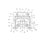
図1の分解図は、本発明による流量センサ1の主な構成を示している。流量センサ1は第一ハウジング部材2と第二ハウジング部材3を有している。該ハウジング部材2,3は、ダイキャスティング技術の手段によって、亜鉛−アルミニウム合金のような熱良導材料の合金から作ることができる。上記ハウジング部材2,3は、互いに嵌合されることにより、すなわち、内側表面4,5が互いに接して位置することにより、組み立てられる。それらは、ほぞ孔とほぞとの接合によって心出しされる。同図の場合、ほぞはハウジング部材2の内側表面の突部26,26Aによって形成され、ほぞ孔は突部に適合するハウジング3の開口部によって形成される。これは、ハウジング部材をトレイに配置し、センサ管を一方の該ハウジング部材に配置して、該ハウジング部材をロボットによって互いに嵌合させる工程の自動化を可能とする。
The exploded view of FIG. 1 shows the main configuration of a
参照番号6はセンサ管を示す。この例では、このセンサ管6は、一つの部材からなる、外径0.3mmそして内径0.2mmのステンレス鋼の毛細管である。センサ管6はU字形に湾曲されており、連結管9に連結される脚管7および8を一体に有する形態をなしている。脚管7は測定されるべき流れΦを受け入れる入口部を有し、脚管8は測定されるべき流れΦのための出口部を有する。連結管9は、該連結管と熱良導接触している抵抗素子10および11を支持している。図1では、抵抗素子は連結管9を巻くように設けられた電気巻き線として構成されている。しかしながら、本発明はこの実施形態に限定されない。組立ての際、センサ管6は、ハウジング部材2の内側表面4に設けられた溝に、電気抵抗素子10,11とともに配置される。このようにして、U字形のセンサ管の主面は、ハウジング部材2の内側表面と(そして組立後はハウジング3の内側表面とも)平行となる。ハウジング部材2における溝のパターンはU字形のセンサ管6に沿っている。溝のパターンは異なる幅および深さの溝で構成されている。これはすべて、図1のハウジング部材2の断面図である図2にて明確に示されている。
Reference numeral 6 denotes a sensor tube. In this example, the sensor tube 6 is a single-member stainless steel capillary tube having an outer diameter of 0.3 mm and an inner diameter of 0.2 mm. The sensor tube 6 is curved in a U shape, and has a form in which
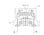
U字形の管の湾曲部14および15に適合する溝12および13は、ここで示される実施形態において重要である。該溝12および13は(そしてハウジング部材3の溝12Aおよび13Aも)底部を有しており、組立後、局所的かつ熱的にクランプするために湾曲部が該底部に配置されるように該溝12,13の底部は隣接した溝の底部よりも高くなっており(すなわち、溝が浅くなっており)、より広く深い溝16が溝12と13との間に形成されている。この溝16は組立後におけるU字形管6の作動部分、すなわち互いに離れた側に位置している電気巻き線10および11の端部同士間に位置する連結管9の部分を包囲する。この例では、該作動部分は溝16の壁および底部とは隙間を形成していて完全に自由な状態で配置される。溝16の幅および深さは、好ましくは、作動中、溝内の空気が静止した状態を可能な限り確保するために、上記作動部分が小さな隙間をもって包囲されている。抵抗素子と溝16の壁との間の距離は、例えば、0.1ミリメートルのオーダである。センサ管6の脚管7,8は、それらの入口部19,出口部20が溝12,13よりも僅かに深い溝21,22で案内される。結果として、該端部間の距離が固定され、例えば、質量流量制御装置の他の要素との組立てが容易となる。入口部19,出口部20はシール部材(ガスケット)23,24を貫通して外部へ延びている(図2参照)。該シール部材23,24はエラストマー材料で作ることができる。
湾曲部がクランプされた溝12,13および12A,13Aは、好ましくは平坦な底部を有している。センサ管の端部が案内されている溝21,22および21A,22Aは、丸い底部を有していてもよい。しかしながら、本発明は、これに限定されない。
The
好ましくは第一ハウジング部材2の溝のパターンに対応する溝のパターンを有する第二ハウジング部材3が、最終的な組立時に、第一ハウジング部材2上に配置されたとき、センサ管6は、湾曲部の領域にてハウジング部材2,3に熱的に接触するように、すなわち、熱的にクランプされるようにもたらされる。この目的のために両ハウジング部材は、ハウジング部材3を通ってハウジング部材2のタップ孔に螺入するボルト(図示せず)によって互いに締め付けられる。クランプされている間、U字形のセンサ管6の湾曲部は僅かに歪んでいても(扁平になっても)よい。組立後において、U字形のセンサ管6の入口部19,出口部20は組み立てられたハウジング部材2,3から僅かに突出する。入口部19,出口部20は、溝21,22と溝21A,22Aとの組み合わせによって案内されてハウジングの外部にて固定された相互の距離を保っている。したがって、センサ1は質量流量制御装置のベース部分に容易に取り付けることができる。ハウジング部材2,3における低位置にある部分30,30’はベース部分と一体としてもよい。それらは、質量流量制御装置のベース部分へのハウジング部材2,3の取付けを可能とするそれぞれの孔部が設けられた締付け要素31,31’を有する。図1において、ハウジング部材2の内側表面の溝12,13,16,21,および22と対応する、ハウジング部材3の内側表面5の溝(「対応溝」)には、参照番号12A,13A,16A,21Aおよび22Aが付されている。
When the second housing member 3, preferably having a groove pattern corresponding to the groove pattern of the
ハウジング部材2,3はそれぞれ、U字形センサ管に適合した溝のパターンの他に中央凹部25,25Aが形成されている。これらの中央凹部は、接続箔または接続(プリント回路)板のような接続要素を設置するための空間を提供する。上記接続要素は図2に示す構成で見ることができる。一方の側では、電気巻き線と接続されている接続電線が接続されており、他方の側では、より太い電線27,28,29が外部の回路との接続をもたらしている。プリント回路基板は脚管に固定されていてもよい。センサ管が比較的太い場合には、該センサ管は、ハウジング内にて、プリント回路基板の「下」の外部に近い位置で熱的にクランプされていてもよい。
Each of the
図3は、図1および図2のハウジング部材2の他の実施形態を示す断面図である。
FIG. 3 is a cross-sectional view showing another embodiment of the
図2の構成との相違点は、図3の場合では、抵抗素子36および37の間の位置にてU字形のセンサ管35の作動部分34を包囲している溝33に、作動部分34を配置する立壁部32Aが設けられている点である。ハウジング部材32が、対応する溝(図示せず)のパターンを有する対応ハウジング部材と組み立てられたとき、センサ管35は電気抵抗素子36と37の間の位置にて熱的にクランプされる。
2 differs from the configuration of FIG. 2 in that, in the case of FIG. 3, the operating
このようにして、作動中、巻き線36および37の間にて、熱はセンサ管からハウジングへ移動する。このことは、熱的流量センサ装置をCT法によって作動させるときに正確な測定値を得るために重要である。もし抵抗素子36をセンサ、そして抵抗素子37をヒータとして使用するならば、ヒータ37からセンサ36への好ましくないいかなる影響をも妨げるためには、ハウジング部材32および対応ハウジング部材における熱的な接触部分(立壁部)32Aが、ヒータ37よりもセンサ36の近く(好ましくは、センサ36に可能な限り近く)に位置していることが重要である。このことは全て、図4を参照してさらに説明される。
In this manner, during operation, heat is transferred from the sensor tube to the housing between the
「U字形の管」なる表現は、連結管によって連結された二つの脚管のいかなる構成をも意味している。例えば、脚管が、連結管の両端位置よりも短い距離で該脚管の端部が位置している構成である。 The expression “U-shaped tube” means any configuration of two leg tubes connected by a connecting tube. For example, the leg tube is configured such that the end portion of the leg tube is positioned at a distance shorter than the both end positions of the connecting tube.
図1から図3では、U字形管の湾曲部の領域でのクランプを示したが、該クランプは、これに代えて、湾曲部と電気抵抗素子の端部との間におけるそれぞれの位置や、湾曲部と脚管の入口部および出口部との間におけるそれぞれの位置でなされてもよい。 In FIGS. 1 to 3, the clamp in the region of the curved portion of the U-shaped tube is shown, but instead of the clamp, each position between the curved portion and the end of the electric resistance element, It may be made at each position between the curved portion and the entrance portion and the exit portion of the leg tube.
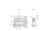
図4Aは、本発明による流量センサのための、二つの部分からなるハウジング38の概要を示す縦断面図であり、図4Bは、図4AにおけるIV線断面図である。ハウジング部材39は、二つの隣接する電気抵抗素子AおよびBが設けられたU字形のセンサ管40に適合する凹部(溝)が形成された形態で示されている。センサ管40は、二つの湾曲部41および42を有している。これらの湾曲部は、ハウジング部材39の内側表面に形成されたそれぞれの凹部(溝)43,44内で、本実施形態にて(上記内側表面と接触することなく)抵抗素子A,Bが設けられたセンサ管40の部分とともに自由な状態で配置されている。凹部43と44との間で、センサ管40は、より浅い凹部45の内側表面に配置される。そのようなより浅い凹部は対応ハウジング部材39’(図4B)にも形成されており、したがって、センサ管40は、ハウジング部材39’がハウジング部材39に対して組み立てられたとき、ハウジング部材の間で局所的にクランプされる。そして、CT法の改良で望まれるように、センサ管からの熱はハウジングへ直接移動することが可能となる。
4A is a longitudinal sectional view showing an outline of a two-
図4Aで示される形態では、さらに、ハウジング部材39が対応ハウジング部材39’と接合したとき(図4B)、それぞれの抵抗素子A,Bから離れた側で浅い凹部48,49に適合するU字形のセンサ管40の脚管46,47が湾曲部41,42の下側で熱的にクランプされている。その結果、外部の温度勾配は、抵抗素子AおよびBの互いに離れて位置する端部同士の間に位置するセンサ管40の作動部分に及ばない。比較のため、図1から図3に示されるセンサ管は熱的に湾曲部の領域でクランプされている。
In the form shown in FIG. 4A, when the
図4Aおよび図4Bに示されるように、ハウジング部材39および39’で形成されるハウジング38はベース61に配置される。自由な状態で中央凹部62を貫通して延びる、センサ管40の脚管46,47は、ベース61の筒状部50,51を通って外部へ延出する。ベース61は別体として分離形成された要素であってもよいし、ハウジング部材39,39’と一体となった要素であってもよい。ベース61には、必要な回路が配されたプリント回路基板を内部に有する立壁部が設けられていてもよい。
As shown in FIGS. 4A and 4B, the
図5Aは、本発明による流量センサのためのハウジングの概要を示す縦断面図であり、図5Bは、図5AにおけるV線断面図である。これらの図は、図4Aと図4Bに示された構成に代わる構成を示す。ここでは、脚管52,53は、図4A,4Bの構成における溝48,49よりも長い範囲で、(浅い)溝55,56により保持されているので、U字形のセンサ管54の脚管52,53が、より長い距離にわたって確実にクランプされる。
FIG. 5A is a longitudinal sectional view showing an outline of a housing for a flow sensor according to the present invention, and FIG. 5B is a sectional view taken along line V in FIG. 5A. These figures show an alternative configuration to that shown in FIGS. 4A and 4B. Here, since the
図5Aでは、ハウジング部材60の内側表面の溝55,56は湾曲部の下側からベース59に向かってまっすぐに延びている。図4の構成と同様、この構成においても、センサ管54の熱的なクランプは、抵抗素子A’とB’との間でなされてもよい。
In FIG. 5A, the
「U字形の管」なる表現は、連結管によって連結された二つの脚管のいかなる構成をも意味している。例えば、脚管が、連結管の両端位置よりも短い距離で該脚管の端部が位置している構成である。 The expression “U-shaped tube” means any configuration of two leg tubes connected by a connecting tube. For example, the leg tube is configured such that the end portion of the leg tube is positioned at a distance shorter than the both end positions of the connecting tube.
図1から図3では、U字形管の湾曲部の領域でのクランプを示したが、該クランプは、これに代えて、湾曲部と電気抵抗素子の端部との間におけるそれぞれの位置や、湾曲部と脚管の入口部および出口部との間におけるそれぞれの位置でなされてもよい。 In FIG. 1 to FIG. 3, the clamp in the region of the curved portion of the U-shaped tube is shown, but instead of the clamp, each position between the curved portion and the end of the electric resistance element, It may be made at each position between the curved portion and the entrance portion and the exit portion of the leg tube.
一般的に、センサ管は、温度のプロファイルがちょうど終わる部分で熱的にクランプされているのが好ましい。換言すると、センサ管のクランプはセンサ(実際には巻き線)の熱プロファイルに依存する。 In general, the sensor tube is preferably thermally clamped at the point where the temperature profile just ends. In other words, the clamping of the sensor tube depends on the thermal profile of the sensor (actually the winding).
さらに、本発明による流量センサの特定の形態では、連結管にて互いに隣り合っている、好ましくは連結管の中央に対して対称に位置している二つの巻き線(抵抗素子)が設けられている。ベースにおける温度勾配がセンサの作動部分に到達する前に該温度勾配を平らにするために、ハウジング部材は、作動中、連結管が最上位置に配置されるハウジングを形成する。 Furthermore, in a particular embodiment of the flow sensor according to the invention, two windings (resistive elements) are provided that are adjacent to each other in the connecting pipe, preferably symmetrically with respect to the center of the connecting pipe. Yes. In order to flatten the temperature gradient before the temperature gradient at the base reaches the working part of the sensor, the housing member forms a housing in which the connecting tube is placed in the uppermost position during operation.
「局所的なクランプ」なる表現は、ここでは、適切で有効な経路の一部にわたるクランプ、例えば、センサ管の入口部と上流の抵抗素子との間の経路の一部にわたる、または、センサ管の出口部と下流の抵抗素子との間の経路の一部にわたるクランプを意味する。 The expression “local clamp” here refers to a clamp over a part of the appropriate and effective path, eg over a part of the path between the inlet of the sensor tube and the upstream resistive element, or Means a clamp over a part of the path between the outlet of the resistor and the downstream resistive element.
1 流量センサ
2 第一ハウジング部材
3 第二ハウジング部材
4,5 内側表面
6 センサ管
7,8 脚管
9 連結管
10,11 電気抵抗素子
19 入口部
20 出口部
DESCRIPTION OF
Claims (10)
上記ハウジングは、凹部が形成された内側表面(4,5)、および外側表面のそれぞれを有する、熱良導材料の第一および第二のハウジング部材(2,3)を含んでいて、ハウジング部材は該ハウジング部材の内側表面(4,5)が互いに対向して位置しており、U字形のセンサ管(6)は、上記内側表面(4,5)に平行に延びる主面を有し、ハウジング部材(2,3)がU字形のセンサ管(6)の連結管(9)と脚管(7,8)とを包囲しており、上記センサ管(6)は、入口部(19)と上流の抵抗素子(10)との間の第一の位置におけるハウジング部材(2,3)同士の間で局所的かつ熱的にクランプされていて、かつ、出口部(20)と下流の抵抗素子(11)との間の第二の位置におけるハウジング部材(2,3)同士の間で局所的かつ熱的にクランプされていることを特徴とする熱型流量センサ装置。 A U-shaped sensor tube (6) and a housing, the sensor tube (6) being formed by two leg tubes (7, 8) and a connecting tube (9) connecting the two leg tubes; A sensor pipe (6) in which two adjacent electric resistance elements (10, 11) are provided in the connecting pipe (9) includes an inlet part (19) for inflow and an outlet part (20) for outflow. In a thermal mass sensor device having
The housing includes first and second housing members (2, 3) of thermally conductive material having respective inner surfaces (4, 5) formed with recesses and outer surfaces. The inner surfaces (4, 5) of the housing member are located opposite to each other, the U-shaped sensor tube (6) has a main surface extending parallel to the inner surface (4, 5), The housing members (2, 3) surround the connecting pipe (9) and the leg pipes (7, 8) of the U-shaped sensor pipe (6), and the sensor pipe (6) has an inlet portion (19). Is locally and thermally clamped between the housing members (2, 3) in a first position between the outlet element (10) and the upstream resistive element (10), and the outlet part (20) and the downstream resistance Between the housing members (2, 3) in the second position between the elements (11) Thermal flow sensor device characterized by being Tokoro and thermally clamped.
Applications Claiming Priority (1)
| Application Number | Priority Date | Filing Date | Title |
|---|---|---|---|
| NL1032007A NL1032007C2 (en) | 2006-06-14 | 2006-06-14 | Thermal sensor flow sensor. |
Publications (2)
| Publication Number | Publication Date |
|---|---|
| JP2007333735A true JP2007333735A (en) | 2007-12-27 |
| JP2007333735A5 JP2007333735A5 (en) | 2010-05-20 |
Family
ID=37685940
Family Applications (1)
| Application Number | Title | Priority Date | Filing Date |
|---|---|---|---|
| JP2007145880A Pending JP2007333735A (en) | 2006-06-14 | 2007-05-31 | Flow sensor of thermal type |
Country Status (8)
| Country | Link |
|---|---|
| US (1) | US7437928B2 (en) |
| EP (1) | EP1867962B1 (en) |
| JP (1) | JP2007333735A (en) |
| AT (1) | ATE461432T1 (en) |
| DE (1) | DE602007005306D1 (en) |
| DK (1) | DK1867962T3 (en) |
| ES (1) | ES2340724T3 (en) |
| NL (1) | NL1032007C2 (en) |
Cited By (1)
| Publication number | Priority date | Publication date | Assignee | Title |
|---|---|---|---|---|
| JP2017101955A (en) * | 2015-11-30 | 2017-06-08 | アズビル株式会社 | Measuring apparatus and method for manufacturing measuring apparatus |
Families Citing this family (11)
| Publication number | Priority date | Publication date | Assignee | Title |
|---|---|---|---|---|
| US7971480B2 (en) * | 2008-10-13 | 2011-07-05 | Hitachi Metals, Ltd. | Mass flow controller having a first pair of thermal sensing elements opposing a second pair of thermal sensing elements |
| NL2011975C2 (en) | 2013-12-17 | 2015-06-18 | Berkin Bv | FLOW MEASURING DEVICE OF THE THERMAL TYPE. |
| NL2012126C2 (en) | 2014-01-23 | 2015-07-29 | Berkin Bv | Flow measurement system and method for determining at least one property of a medium. |
| US9791307B2 (en) * | 2015-03-06 | 2017-10-17 | Alicat Scientific, Inc. | Systems and methods for detecting flow of a fluid |
| WO2017154513A1 (en) * | 2016-03-11 | 2017-09-14 | 日立金属株式会社 | Thermal mass flow rate sensor, thermal mass flow rate sensor production method, and thermal mass flow meter using said thermal mass flow rate sensor |
| CN106768113B (en) * | 2016-12-09 | 2019-10-25 | 北京七星华创流量计有限公司 | A kind of fluid conveying measuring device |
| CN110462348B (en) * | 2017-03-30 | 2021-08-10 | 富士金公司 | Mass flow sensor, mass flow meter provided with mass flow sensor, and mass flow controller provided with mass flow sensor |
| NL2021082B1 (en) | 2018-06-08 | 2019-12-11 | Berkin Bv | Pressure-insensitive thermal type flow meter |
| FR3096452B1 (en) | 2019-05-22 | 2022-02-11 | Buerkert Werke Gmbh & Co Kg | Mass flow sensor assembly and method of making a mass flow sensor assembly |
| JP7467887B2 (en) * | 2019-11-01 | 2024-04-16 | オムロン株式会社 | Plant Biosensor |
| NL2026167B1 (en) | 2020-07-30 | 2022-04-08 | Berkin Bv | Thermal-type flow sensor with a thermally conductive frame element in the form of a printed circuit board (PCB) |
Citations (3)
| Publication number | Priority date | Publication date | Assignee | Title |
|---|---|---|---|---|
| JPS5988622A (en) * | 1982-11-12 | 1984-05-22 | Ohkura Electric Co Ltd | Thermal type mass flowmeter |
| JPS62278411A (en) * | 1986-05-27 | 1987-12-03 | Esutetsuku:Kk | Thermal flowmeter |
| US5191793A (en) * | 1984-03-12 | 1993-03-09 | Tylan Corporation | Fluid mass flow meter device with reduced attitude sensitivity |
Family Cites Families (5)
| Publication number | Priority date | Publication date | Assignee | Title |
|---|---|---|---|---|
| JP3047184B2 (en) * | 1989-11-27 | 2000-05-29 | 株式会社エステック | Mass flow meter |
| WO1991019959A1 (en) * | 1990-06-14 | 1991-12-26 | Unit Instruments, Inc. | Thermal mass flow sensor |
| US5792952A (en) * | 1996-05-23 | 1998-08-11 | Varian Associates, Inc. | Fluid thermal mass flow sensor |
| US6779394B2 (en) * | 2001-12-21 | 2004-08-24 | Mks Instruments, Inc. | Apparatus and method for thermal management of a mass flow controller |
| NL1023405C2 (en) | 2003-05-13 | 2004-11-18 | Berkin Bv | Mass flow meter. |
-
2006
- 2006-06-14 NL NL1032007A patent/NL1032007C2/en not_active IP Right Cessation
-
2007
- 2007-05-15 AT AT07075369T patent/ATE461432T1/en active
- 2007-05-15 DE DE602007005306T patent/DE602007005306D1/en active Active
- 2007-05-15 ES ES07075369T patent/ES2340724T3/en active Active
- 2007-05-15 EP EP07075369A patent/EP1867962B1/en not_active Not-in-force
- 2007-05-15 DK DK07075369.4T patent/DK1867962T3/en active
- 2007-05-18 US US11/798,983 patent/US7437928B2/en active Active
- 2007-05-31 JP JP2007145880A patent/JP2007333735A/en active Pending
Patent Citations (3)
| Publication number | Priority date | Publication date | Assignee | Title |
|---|---|---|---|---|
| JPS5988622A (en) * | 1982-11-12 | 1984-05-22 | Ohkura Electric Co Ltd | Thermal type mass flowmeter |
| US5191793A (en) * | 1984-03-12 | 1993-03-09 | Tylan Corporation | Fluid mass flow meter device with reduced attitude sensitivity |
| JPS62278411A (en) * | 1986-05-27 | 1987-12-03 | Esutetsuku:Kk | Thermal flowmeter |
Cited By (1)
| Publication number | Priority date | Publication date | Assignee | Title |
|---|---|---|---|---|
| JP2017101955A (en) * | 2015-11-30 | 2017-06-08 | アズビル株式会社 | Measuring apparatus and method for manufacturing measuring apparatus |
Also Published As
| Publication number | Publication date |
|---|---|
| ATE461432T1 (en) | 2010-04-15 |
| US20070295079A1 (en) | 2007-12-27 |
| EP1867962B1 (en) | 2010-03-17 |
| DK1867962T3 (en) | 2010-06-28 |
| EP1867962A1 (en) | 2007-12-19 |
| ES2340724T3 (en) | 2010-06-08 |
| DE602007005306D1 (en) | 2010-04-29 |
| US7437928B2 (en) | 2008-10-21 |
| NL1032007C2 (en) | 2007-12-17 |
Similar Documents
| Publication | Publication Date | Title |
|---|---|---|
| JP2007333735A (en) | Flow sensor of thermal type | |
| KR102277609B1 (en) | Thermal type flow meter | |
| JP4836988B2 (en) | Thermal flow meter | |
| US10274353B2 (en) | Flow sensor with hot film anemometer | |
| JP5737477B2 (en) | Flow meter, dialysis machine, chemical solution injection device | |
| JP2007529749A (en) | High precision measurement and control of low flow rate fluid | |
| JP2006029966A (en) | Multi-vortex flowmeter | |
| JP2005514613A (en) | Apparatus and method for thermal management of mass flow controller | |
| JP2006010322A (en) | Thermal flowmeter | |
| KR102099522B1 (en) | Electrical connector, fluid condition testing device and fluid heat exchange system | |
| KR101519837B1 (en) | flow meter using heat pulse | |
| JP2018072237A (en) | Measurement device | |
| WO2018180387A1 (en) | Mass flow sensor, mass flow meter provided with mass flow sensor, and mass flow controller provided with mass flow sensor | |
| JP4097088B2 (en) | Sensor support type thermal mass flow meter | |
| CN216201097U (en) | Instant hot water device with cold/hot water path and faucet | |
| US20040226359A1 (en) | Mass flowmeter for measuring by the CT method | |
| JP2019082346A (en) | Thermal flowmeter | |
| JP2019086381A (en) | Thermal flowmeter | |
| JP5492802B2 (en) | Vortex flow meter and method for manufacturing the same | |
| JP3267943B2 (en) | Thermal flow meter | |
| KR200250405Y1 (en) | A Thermal Level Measuring Device | |
| JPS6361918A (en) | Insertion type thermal flow meter | |
| JP2019164046A (en) | Thermal flowmeter | |
| JP2019086380A (en) | Thermal flowmeter | |
| JPH0499916A (en) | Vortex flowmeter |
Legal Events
| Date | Code | Title | Description |
|---|---|---|---|
| A521 | Request for written amendment filed |
Free format text: JAPANESE INTERMEDIATE CODE: A523 Effective date: 20100401 |
|
| A621 | Written request for application examination |
Free format text: JAPANESE INTERMEDIATE CODE: A621 Effective date: 20100401 |
|
| A977 | Report on retrieval |
Free format text: JAPANESE INTERMEDIATE CODE: A971007 Effective date: 20120228 |
|
| A131 | Notification of reasons for refusal |
Free format text: JAPANESE INTERMEDIATE CODE: A131 Effective date: 20120301 |
|
| A601 | Written request for extension of time |
Free format text: JAPANESE INTERMEDIATE CODE: A601 Effective date: 20120515 |
|
| A602 | Written permission of extension of time |
Free format text: JAPANESE INTERMEDIATE CODE: A602 Effective date: 20120518 |
|
| A521 | Request for written amendment filed |
Free format text: JAPANESE INTERMEDIATE CODE: A523 Effective date: 20120821 |
|
| A02 | Decision of refusal |
Free format text: JAPANESE INTERMEDIATE CODE: A02 Effective date: 20120904 |