JP2007331066A - Contact presenting device and method - Google Patents
Contact presenting device and method Download PDFInfo
- Publication number
- JP2007331066A JP2007331066A JP2006166205A JP2006166205A JP2007331066A JP 2007331066 A JP2007331066 A JP 2007331066A JP 2006166205 A JP2006166205 A JP 2006166205A JP 2006166205 A JP2006166205 A JP 2006166205A JP 2007331066 A JP2007331066 A JP 2007331066A
- Authority
- JP
- Japan
- Prior art keywords
- human body
- stimulus
- contact
- generating means
- vibration motor
- Prior art date
- Legal status (The legal status is an assumption and is not a legal conclusion. Google has not performed a legal analysis and makes no representation as to the accuracy of the status listed.)
- Pending
Links
- 238000000034 method Methods 0.000 title claims description 56
- 230000008447 perception Effects 0.000 claims description 18
- 230000001133 acceleration Effects 0.000 description 14
- 239000003550 marker Substances 0.000 description 11
- 238000010586 diagram Methods 0.000 description 8
- 210000003811 finger Anatomy 0.000 description 8
- 238000001514 detection method Methods 0.000 description 7
- 230000035807 sensation Effects 0.000 description 4
- 230000000638 stimulation Effects 0.000 description 4
- 230000015572 biosynthetic process Effects 0.000 description 3
- 230000006399 behavior Effects 0.000 description 2
- OEBRKCOSUFCWJD-UHFFFAOYSA-N dichlorvos Chemical compound COP(=O)(OC)OC=C(Cl)Cl OEBRKCOSUFCWJD-UHFFFAOYSA-N 0.000 description 2
- 230000010365 information processing Effects 0.000 description 2
- 239000000463 material Substances 0.000 description 2
- 102000005962 receptors Human genes 0.000 description 2
- 108020003175 receptors Proteins 0.000 description 2
- 210000002265 sensory receptor cell Anatomy 0.000 description 2
- 102000027509 sensory receptors Human genes 0.000 description 2
- 108091008691 sensory receptors Proteins 0.000 description 2
- 241000282412 Homo Species 0.000 description 1
- 125000002066 L-histidyl group Chemical group [H]N1C([H])=NC(C([H])([H])[C@](C(=O)[*])([H])N([H])[H])=C1[H] 0.000 description 1
- 206010040007 Sense of oppression Diseases 0.000 description 1
- 210000003423 ankle Anatomy 0.000 description 1
- 230000037237 body shape Effects 0.000 description 1
- 238000007796 conventional method Methods 0.000 description 1
- 238000013461 design Methods 0.000 description 1
- 238000011161 development Methods 0.000 description 1
- 230000000694 effects Effects 0.000 description 1
- 238000005516 engineering process Methods 0.000 description 1
- 210000004247 hand Anatomy 0.000 description 1
- 210000003127 knee Anatomy 0.000 description 1
- 238000009940 knitting Methods 0.000 description 1
- 210000002414 leg Anatomy 0.000 description 1
- 239000004973 liquid crystal related substance Substances 0.000 description 1
- 210000004932 little finger Anatomy 0.000 description 1
- 230000003287 optical effect Effects 0.000 description 1
- 229920000642 polymer Polymers 0.000 description 1
- 238000012545 processing Methods 0.000 description 1
- 230000001953 sensory effect Effects 0.000 description 1
- 229910001285 shape-memory alloy Inorganic materials 0.000 description 1
Images


Classifications
-
- G—PHYSICS
- G06—COMPUTING; CALCULATING OR COUNTING
- G06F—ELECTRIC DIGITAL DATA PROCESSING
- G06F3/00—Input arrangements for transferring data to be processed into a form capable of being handled by the computer; Output arrangements for transferring data from processing unit to output unit, e.g. interface arrangements
- G06F3/01—Input arrangements or combined input and output arrangements for interaction between user and computer
- G06F3/016—Input arrangements with force or tactile feedback as computer generated output to the user
Landscapes
- Engineering & Computer Science (AREA)
- General Engineering & Computer Science (AREA)
- Theoretical Computer Science (AREA)
- Human Computer Interaction (AREA)
- Physics & Mathematics (AREA)
- General Physics & Mathematics (AREA)
- User Interface Of Digital Computer (AREA)
- Manipulator (AREA)
- Apparatuses For Generation Of Mechanical Vibrations (AREA)
Abstract
Description
本発明は、接触提示装置及び方法に関し、特に、バーチャルリアリティの分野において、仮想物体との接触をユーザに知覚させるための接触提示装置及び方法に関する。 The present invention relates to a contact presentation apparatus and method, and more particularly to a contact presentation apparatus and method for allowing a user to perceive contact with a virtual object in the field of virtual reality.
ユーザにバーチャルリアリティを提供する技術分野では、ユーザが、仮想物体に触れたり、操作したりするために触覚ディスプレイの検討が行われている。 In the technical field of providing virtual reality to a user, a tactile display has been studied for a user to touch or operate a virtual object.
触覚ディスプレイは大きく分類して、人体に物体からの反力を提示する力覚ディスプレイ(フォース・フィードバック・ディスプレイ)と、物体の“手触り感”を提示するタクタイルディスプレイに分類される。しかし、従来の力覚ディスプレイは、大型で可搬性に乏しい物が多く、また構成が複雑で高価になりやすい。また、タクタイルディスプレイも、装置の構成が複雑になりやすく、現状の技術では十分に“手触り感”を提示することが容易ではない。 The tactile display is roughly classified into a force display (force feedback display) that presents a reaction force from an object to the human body and a tactile display that presents a “hand touch” of the object. However, many conventional haptic displays are large and have poor portability, and the configuration is complicated and expensive. In addition, the tactile display is also likely to have a complicated apparatus configuration, and it is not easy to present a sufficient “feel” with the current technology.
そこで、仮想物体からの十分な反力や正確な“手触り感”を提示しないまでも、「接触したかどうか」を提示する接触提示装置が検討されている。この方法では、振動モータを人体に装着し、仮想物体と触れた時に適当な位置の振動モータを振動させ、物体との接触をユーザに知覚させる。この接触提示装置により、ユーザは身体のどの部分が物体に触れているかを知覚することができる。また、振動モータは小型、安価、軽量であることから、人体の全体に装着することも比較的容易であることから、移動自由度の高いバーチャルリアリティシステムでは特に有効である。 In view of this, a contact presentation device that presents “whether or not it is touched” has been studied even if a sufficient reaction force from a virtual object and an accurate “feel” are not presented. In this method, a vibration motor is attached to a human body, and when a virtual object is touched, the vibration motor at an appropriate position is vibrated, and the user is perceived to be in contact with the object. With this contact presentation device, the user can perceive which part of the body is touching the object. In addition, since the vibration motor is small, inexpensive, and lightweight, it is relatively easy to attach it to the entire human body, and thus is particularly effective in a virtual reality system with a high degree of freedom of movement.
振動モータを用いた従来の接触提示装置には、例えば、次のようなものがある。 Examples of conventional contact presentation devices using a vibration motor include the following.
特許文献1は、指先の位置を取得するためのデータグローブに振動モータを設置し、指先に振動を与えることで、指先と仮想物体の接触をユーザに知覚させるものである。
また、非特許文献1は、全身に計12個の振動モータを装着し、仮想壁との接触時に振動モータを振動させることで、ユーザに壁を認知させる装置を提案している。この非特許文献1における振動モータ装着位置は、人体感覚図から判断し、頭、手の甲、肘、胴回り(3個)、膝、足首である。
Non-Patent
また、非特許文献2では、腕4カ所、脚4カ所に振動モータを装着し、振動モータの振動を変化させて、異なる質感の物体への接触を提示している。 In Non-Patent Document 2, vibration motors are attached to four arms and four legs, and the vibration of the vibration motor is changed to present contact with an object having a different texture.
また、非特許文献3では、戦場シミュレータ用に、振動モータを人体に装着した装置を開発している。この非特許文献3では、振動モータ制御を無線で行うことが特徴である。 Non-Patent Document 3 has developed a device in which a vibration motor is mounted on a human body for a battlefield simulator. This non-patent document 3 is characterized in that vibration motor control is performed wirelessly.
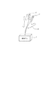
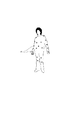
従来の振動モータを使用した接触提示装置の構成例を、図20に示す。 FIG. 20 shows a configuration example of a contact presentation device using a conventional vibration motor.
図20では、振動モータ10を人体に装着している。また、ユーザは仮想物体を見るためにヘッドマウントディスプレイ100を装着している。また、仮想物体との接触を検知するために、人体の位置情報が必要であるため、人体の各部位に位置検出用のマーカ108を設置している。マーカは従来の手法では光学マーカや画像マーカが使われている。これらの構成により、ユーザの位置姿勢を検出し、仮想物体との接触を判定した後に、接触部位に最も近い部位に装着している振動モータ10を振動させる。ユーザは振動した部分が、仮想物体と接触していることを知覚する。
上記の従来技術では、振動モータを利用しているため、仮想物体との接触を簡単にユーザに教示することはできていたが、それ以上の情報を提示することは困難であった。 In the above prior art, since a vibration motor is used, it has been possible to easily teach a user to contact a virtual object, but it has been difficult to present more information.
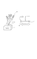
従来、力覚ディスプレイやタクタイルディスプレイでは、仮想物体形状や仮想物体表面の“手触り”をユーザに知覚させるため、様々な試みが行われてきた。一方、単純なアクチュエータである振動モータでは、繊細な触覚の表現を行うことが十分にできていない。振動モータによる表現力向上の試みとして、非特許文献2では、接触した壁の種類を提示するために、壁の材質ごとに振動のモデルを予め用意しておき、壁との接触時にモデルに基づいた振動を与えている。しかし、この手法では壁の材質を知覚させることが十分にできてはいない。 Conventionally, in a haptic display and a tactile display, various attempts have been made to make the user perceive the virtual object shape and the “hand touch” of the virtual object surface. On the other hand, a vibration motor that is a simple actuator cannot sufficiently express a delicate tactile sensation. In an attempt to improve the expressive power using a vibration motor, Non-Patent Document 2 prepares a vibration model for each wall material in advance in order to present the type of wall in contact, and based on the model at the time of contact with the wall. Giving vibration. However, this method is not enough to perceive the wall material.
以上のように、振動モータは小型、安価、軽量であることから、人体の任意の部位に設置して、簡単に仮想物体との接触を提示することが可能であるが、接触情報以上の多彩な表現を行うことは困難であった。特に、平面や物体表面を知覚させることは困難であった。 As described above, since the vibration motor is small, inexpensive, and lightweight, it can be installed in any part of the human body and easily presents contact with a virtual object. It was difficult to make a proper expression. In particular, it was difficult to perceive a plane or an object surface.
本発明では、振動モータのような単純な構成の刺激発生装置であっても、ユーザに平面や物体表面を感じさせることができる等の表現力が向上した接触提示装置を提供する。 The present invention provides a contact presentation device with improved expressive power, such as allowing a user to feel a plane or an object surface, even with a stimulus generator having a simple configuration such as a vibration motor.
上記課題を解決するために、本願発明は以下の構成からなる。 In order to solve the above problems, the present invention has the following configuration.
即ち、本発明の接触提示装置は、人体に所定の知覚を提示する接触提示装置であって、少なくとも2つ以上の刺激発生手段と、前記刺激発生手段のオン状態とオフ状態を所定のサイクルで設定し、少なくとも2つの刺激発生手段における前記サイクルが異なる制御を行う制御手段とを備えたことを特徴とする。 That is, the contact presentation device of the present invention is a contact presentation device that presents a predetermined perception to the human body, and includes at least two or more stimulus generation units, and an on state and an off state of the stimulus generation unit in a predetermined cycle. Control means for setting and performing control in which the cycle in at least two stimulus generating means is different.
また、本発明の接触提示装置は、人体に、仮想物体と所定の知覚を提示する接触提示装置であって、少なくとも2つ以上の刺激発生手段と、オン状態とオフ状態を所定のサイクルで設定し、前記仮想物体の表面の所定の範囲内に人体が位置するときに、少なくとも2つの刺激発生手段における前記サイクルが異なる制御を行う制御手段とを備えたことを特徴とする。 The contact presentation device of the present invention is a contact presentation device that presents a virtual object and a predetermined perception to a human body, and sets at least two or more stimulus generation means, an on state, and an off state in a predetermined cycle. And a control means for performing control in which the cycles in the at least two stimulus generation means differ when the human body is located within a predetermined range of the surface of the virtual object.
また、本発明の接触提示装置は、人体に所定の知覚を提示する接触提示装置であって、少なくとも2つ以上の刺激発生手段と、前記刺激発生手段を制御する制御手段とを備え、前記少なくとも2つ以上の刺激発生手段の内、少なくとも一つの刺激発生手段をオン状態にし、少なくとも1つの刺激発生手段をオフ状態にして、オン状態またはオフ状態である刺激発生手段を順次変更する制御を行う制御手段とを備えたことを特徴とする。 The contact presentation device of the present invention is a contact presentation device that presents a predetermined perception to the human body, and includes at least two or more stimulus generation units and a control unit that controls the stimulus generation units, At least one of the two or more stimulus generation means is turned on, at least one stimulus generation means is turned off, and the stimulus generation means in the on state or the off state is sequentially changed. And a control means.
更に、本発明の接触提示方法は、人体に所定の知覚を提示する接触提示方法であって、前記刺激発生手段のオン状態とオフ状態を所定のサイクルで設定する設定工程と、人体に設置された少なくとも2つの刺激発生手段における前記サイクルが異なる制御を行う制御工程とを備えたことを特徴とする。 Further, the contact presentation method of the present invention is a contact presentation method for presenting a predetermined perception to the human body, the setting step for setting the on state and the off state of the stimulus generating means in a predetermined cycle, and the contact presenting method. And a control step in which the cycles in the at least two stimulus generating means perform different controls.
また、本発明の接触提示方法は、人体に、仮想物体と所定の知覚を提示する接触提示方法であって、オン状態とオフ状態を所定のサイクルで設定する設定工程と、前記仮想物体の表面の所定の範囲内に人体が位置するときに、人体に設置された少なくとも2つの刺激発生手段における前記サイクルが異なる制御を行う制御工程とを備えたことを特徴とする。 The contact presentation method of the present invention is a contact presentation method for presenting a virtual object and a predetermined perception to a human body, the setting step of setting an on state and an off state in a predetermined cycle, and the surface of the virtual object When the human body is located within the predetermined range, a control step is performed in which the cycles in the at least two stimulus generating means installed in the human body are controlled differently.
また、本発明の接触提示方法は、人体に所定の知覚を提示する接触提示方法であって、少なくとも2つ以上の刺激発生手段と、人体に設置された少なくとも2つ以上の刺激発生手段の内、少なくとも一つの刺激発生手段をオン状態にし、少なくとも1つの刺激発生手段をオフ状態にする第1の制御工程と、所定時間経過後に、オン状態またはオフ状態である刺激発生手段を順次変更する第2の制御工程とを備えたことを特徴とする。 The contact presentation method of the present invention is a contact presentation method for presenting a predetermined perception to the human body, and includes at least two or more stimulus generation means and at least two or more stimulus generation means installed on the human body. A first control step of turning on at least one stimulus generating means and turning off at least one stimulus generating means; and a step of sequentially changing the stimulus generating means in the on state or off state after a predetermined time has elapsed. And 2 control steps.
本発明は、物体表面をユーザに感じさせることができ、表現力が向上した接触提示装置を提供できるようになる。 According to the present invention, it is possible to provide a contact presentation device with which the surface of an object can be felt by a user and the expression power is improved.
以下、本発明の一実施の形態を、図面を用いて詳細に説明する。 Hereinafter, an embodiment of the present invention will be described in detail with reference to the drawings.
(実施の形態1)
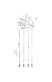
図1は、本発明の実施の形態1に係る接触提示装置の構成を示す図である。
(Embodiment 1)
FIG. 1 is a diagram showing a configuration of a contact presentation device according to
図1に示す接触提示装置は、刺激提示手段として2つの振動モータ10、11と、振動モータ10、11の動作を制御するための制御手段1を備える。図1では振動モータ10、11を指先に付けた例を示しているが、2つの振動モータをある程度近傍に配置すれば、人体のどの部分に装着しても良い。振動モータは、偏心回転子の回転方向が人体の皮膚面内方向に対して水平になるように装着する。また、図1には特に図示していないが、振動モータを指先に装着するための装着手段も備える。装着手段は、例えば、バンドで振動モータを指先に固定する方法や、指サックまたはグローブの指先部分に振動モータを備え、それらを装着する方法で構成される。
The contact presentation apparatus shown in FIG. 1 includes two
なお、制御手段1として、CPU、メモリ(ROM、RAM)、外部インターフェース等を備えるパソコンで構成し、CPUがメモリに格納されたプログラムを実行することにより、以下に説明する制御を行う。 The control means 1 is constituted by a personal computer equipped with a CPU, memory (ROM, RAM), external interface, etc., and the control described below is performed by the CPU executing a program stored in the memory.
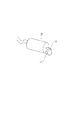
図2に、刺激提示手段として用いる、円筒型の振動モータを示す。 FIG. 2 shows a cylindrical vibration motor used as a stimulus presentation means.
円筒型振動モータ20は、電磁力により編心回転子21を回転させることにより振動を発生する。
The cylindrical vibration motor 20 generates vibration by rotating the knitting
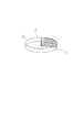
また、刺激提示手段として、コイン型の振動モータを用いてもよい。 A coin-type vibration motor may be used as the stimulus presentation means.
コイン型振動モータ30は、図3に示すように、円板の面内方向に平行に偏心回転子31が回転する。そのため、図1に示すようにコイン型の平板方向を皮膚表面に対して平行になるように装着することにより、偏心回転子31の回転方向が皮膚面内方向に水平になる。円筒型の振動モータを使用した場合では、偏心回転子31の回転方向が皮膚面内方向に水平(回転軸32が皮膚面と垂直)になるように装着する。
As shown in FIG. 3, the coin-
振動モータについては円筒型、コイン型の間で特に動作に違いはなく、どちらを使用しても良い。ただし、偏心回転子の回転方向を人体皮膚表面に対して水平になるように設置するため、省スペースや装着の容易さから、コイン型を用いることが好適である。なお、図1においては、コイン型の振動モータを指先に装着した例を示している。 As for the vibration motor, there is no difference in operation between the cylindrical type and the coin type, and either one may be used. However, since the eccentric rotor is installed so that the rotational direction of the eccentric rotor is horizontal with respect to the human skin surface, it is preferable to use a coin type in terms of space saving and ease of mounting. FIG. 1 shows an example in which a coin-type vibration motor is attached to a fingertip.
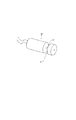
また、本実施の形態では、後述するように、回転の加速と減速に伴い発生するトルクを刺激提示に用いることが特徴である。このため、必ずしも偏心回転子を有する振動モータである必要はなく、図4に示すような均質な回転子41を持つ回転体40を刺激提示手段に用いても良い。この回転体40を使用する場合にも、回転子41の回転方向が皮膚面内方向に水平(回転軸22が皮膚面と垂直)になるように装着し、回転により発生するトルクが皮膚面内方向に水平となるようにする。 Further, as described later, the present embodiment is characterized in that torque generated with acceleration and deceleration of rotation is used for stimulus presentation. For this reason, it is not always necessary to use a vibration motor having an eccentric rotor, and a rotating body 40 having a homogeneous rotor 41 as shown in FIG. 4 may be used as the stimulus presentation means. Even when this rotating body 40 is used, the rotor 41 is mounted so that the rotation direction of the rotor 41 is horizontal to the skin surface direction (the rotation shaft 22 is perpendicular to the skin surface), and the torque generated by the rotation is within the skin surface. Be horizontal in the direction.
以上のように装着した振動モータにより皮膚面内方向に水平な方向にトルクを発生させる。皮膚の面内方向に発生したトルクにより、その反作用による力が皮膚表面に水平な力として加わる。皮膚表面に水平に加わる力により、皮膚表面に水平方向の皮膚変形が生じ、メルケル触小盤を刺激することが期待できる。メルケル触小盤は、SA受容器に分類される感覚受容器で、皮膚変形を検出する。メルケル触小盤が刺激されることにより、人間は圧迫感を知覚する。 Torque is generated in the horizontal direction in the skin surface by the vibration motor mounted as described above. Due to the torque generated in the in-plane direction of the skin, the reaction force is applied as a horizontal force on the skin surface. It can be expected that the force applied horizontally on the skin surface causes horizontal skin deformation on the skin surface and stimulates the Merkel tenac. The Merkel tentacle is a sensory receptor classified as an SA receptor and detects skin deformation. Humans perceive a sense of oppression when the Merkel tenacity is stimulated.
一方、振動モータを用いて通常の振動を発生させた場合には、100〜200Hz付近の振動を発生するため、主にパチニ小体が刺激される。パチニ小体は、RA受容器に分類される感覚受容器で、加速度や振動を検出する。パチニ小体が刺激された場合には、単純な振動を知覚するのみである。 On the other hand, when normal vibration is generated using a vibration motor, vibration in the vicinity of 100 to 200 Hz is generated, so that the Pachiny body is mainly stimulated. Patini bodies are sensory receptors classified as RA receptors and detect acceleration and vibration. When the Pachiny body is stimulated, it only perceives a simple vibration.
以上のように、皮膚面内に水平な方向にトルクを発生することにより、単純に振動を与えた場合とは異なる感覚を発生させることができる。 As described above, by generating torque in a horizontal direction in the skin surface, it is possible to generate a feeling different from that in the case where vibration is simply applied.
次に、振動モータによるトルク発生について説明する。 Next, torque generation by the vibration motor will be described.
振動モータのトルク発生を説明するための図を図5に示す。図5で振動モータ10の偏心回転子21は、時計回り方向に回転する。また、時計回りの方向を正の回転方向とする。時間t0に所定の電圧を振動モータ10に加えると、偏心回転子21は回転を始め、加速時間を経てt1に回転数が一定になる。加速時間には、偏心回転子21の角速度ωが変化するので、正の方向にトルクが発生する。時間t1からt2の間では、振動モータの回転速度は一定となるので、トルクは発生せずに振動のみを発生する状態になる。
FIG. 5 is a diagram for explaining torque generation of the vibration motor. In FIG. 5, the
さらに、時間t2で電圧の印加を停止すると、偏心回転子21の回転速度が減速し時間t3で回転が止まる。減速時間でも、偏心回転子21の角速度ωが変化し、反時計回りのトルクが発生する。以上のことは、以下の式から理解できる。
Further, when the application of voltage is stopped at time t2, the rotational speed of the
角運動量をL、慣性モーメントをI、角速度ωとすると、
L=Iω・・・(1)
トルクNは、
If the angular momentum is L, the moment of inertia is I, and the angular velocity is ω,
L = Iω (1)
Torque N is
![]()
![]()
となり、角速度が変化している期間でトルクが発生する。なお、振動モータではなく、偏心のない回転体を用いた場合にも、トルクの発生原理は同じである。 Thus, torque is generated during the period when the angular velocity is changing. Note that the principle of torque generation is the same when a rotating body without eccentricity is used instead of the vibration motor.
図5では電圧制御により振動モータを駆動しトルクを発生させた。より具体的には、電圧を印加していない状態と、電圧を印加した状態を切り替えることによりトルクを発生させていた。ここでの電圧制御の目的は、偏心回転子21の角速度を変化させてトルクを発生させることであるので、電圧の制御方法は上記に限らない。例えば、電圧印加を完全に停止する必要はなく、任意の値の電圧間で電圧を変化させてトルクを発生させても良い。
In FIG. 5, the vibration motor is driven by voltage control to generate torque. More specifically, torque is generated by switching between a state where no voltage is applied and a state where a voltage is applied. The purpose of the voltage control here is to change the angular velocity of the
より具体的には、1Vと3Vの電圧値を変化させることにより、トルクを発生するように制御しても良い。また、この電圧値には任意の値を用いて良い。またさらに、トルクを発生しない状態も、電圧を印加していない状態以外に、所定の電圧値の継続印加により、偏心回転子21の回転数が一定となった状態を用いても良い。
More specifically, control may be performed so as to generate torque by changing the voltage values of 1V and 3V. Further, an arbitrary value may be used for this voltage value. Furthermore, in a state where no torque is generated, a state where the rotational speed of the
また、振動モータを制御する方法については、電圧を変化させる制御に限定することなく、どのような制御方法を用いても良い。例えば、モータ制御において一般的なPWM制御を用いても良い。PWM制御の場合では、デューティー比を変化させることで、偏心回転子21の角速度を変化させる。デューティー比を変化させる場合でも、電圧値を変化させる場合と同様に、デューティー比の値は任意に設定して良い。
The method for controlling the vibration motor is not limited to the control for changing the voltage, and any control method may be used. For example, general PWM control may be used in motor control. In the case of PWM control, the angular speed of the
図6は、実施の形態1における振動モータの動作について説明する図である。図1では振動モータ10と11をそれぞれ指先に装着した構成を表していた。図6では図1の振動モータ10と11の駆動状態を示している。まず、期間Aでは振動モータ10に電力が供給され、振動モータ10の偏心回転子が回転を開始する。停止状態から偏心回転子の角速度が増加する時間(加速時間)では正方向のトルクが発生する。さらに、期間Aでは、偏心回転子の回転速度が一定になる前に電力供給を停止する。供給電力の停止により、偏心回転子の角速度は減速し、最終的には停止する。偏心回転子の減速により、加速の時とは逆向きの負方向のトルクが発生する。以上が期間Aでの振動モータ10の挙動である。この期間Aの間、振動モータ11は停止している。
FIG. 6 is a diagram for explaining the operation of the vibration motor according to the first embodiment. FIG. 1 shows a configuration in which the
次に、期間Bでは、振動モータ10が停止状態にあり、振動モータ11は期間Aの振動モータ10と同様に、電力供給と電力停止に伴い、正と負の方向のトルクを発生する。また、さらに次の期間Cでは、振動モータ10がトルクを発生し、振動モータ11は停止状態にある。以上の期間A、B、Cで振動モータ10と振動モータ11が発生するトルクを時系列的にまとめると全体のトルクの状況(図の一番下)のように、全体としては常時トルクが発生している状態になる。
Next, in the period B, the
2つの振動モータに、以上のような制御を、所定の条件に基づき繰り返し行うことで、近傍の異なる人体部位(第一の実施例では人差し指と中指)に対して、皮膚面内方向に水平な方向に、交互に力がかかるようになる。 By repeatedly performing the above-described control on the two vibration motors based on predetermined conditions, the two horizontal motors can be horizontally oriented in the skin surface direction with respect to different human body parts in the vicinity (the index finger and the middle finger in the first embodiment). Force is applied alternately in the direction.
このように人体の複数部位に時系列的に力を与えることで、ユーザは異なる人体部位間に連続的なつながりを感じるようになる。特に皮膚表面に対して水平な力を与えていることから、連続的にメルケル触小盤を刺激することが期待できる。その結果、連続的な圧迫感により、実際に平面を触れた場合と同様に、物体平面の空間的なつながりを感じ、あたかも物体の表面を触ったかのような感触を提示することができるようになる。 Thus, by applying force to a plurality of parts of the human body in time series, the user feels continuous connection between different human body parts. In particular, since a horizontal force is applied to the skin surface, it can be expected to continuously stimulate the Merkel tenac. As a result, the feeling of continuous pressure makes it possible to feel the spatial connection of the object planes as if they were actually touching the plane, and to feel as if the surface of the object was touched. .
図6の制御方法では、偏心回転子の角速度が一定になる前に電力供給を停止する必要がある。電力供給から電力停止までの時間は、予め設定しておく方法が簡単である。偏心回転子が停止した状態から、電力供給により定速回転に達するまでの時間を予め測定しておき、その時間以下の範囲で、電力供給から電力停止までの時間を設定すればよい。 In the control method of FIG. 6, it is necessary to stop power supply before the angular velocity of the eccentric rotor becomes constant. A method of setting in advance the time from power supply to power stop is simple. What is necessary is just to measure in advance the time from the state where the eccentric rotor has stopped until reaching constant speed rotation by power supply, and to set the time from power supply to power stop within the time range.
なお、偏心回転子の加速時間は、振動モータの種類や形状などにより異なるが、小型DC振動モータの場合では一般的に100msec程度である。一方、電力停止後、次の振動モータに電力を供給するまでの時間も、同様に偏心回転子の減速時間を予め測定して決定しても良い。 The acceleration time of the eccentric rotor varies depending on the type and shape of the vibration motor, but is generally about 100 msec in the case of a small DC vibration motor. On the other hand, the time until the power is supplied to the next vibration motor after the power is stopped may be similarly determined by measuring the deceleration time of the eccentric rotor in advance.
また、別な方法としては、偏心回転子の回転状況を計測するセンサを備え、所定の角速度または回転数に達した時点で、電力供給を停止したり、次の振動モータに電力を供給するようにしても良い。 As another method, a sensor for measuring the rotation state of the eccentric rotor is provided, and when a predetermined angular velocity or rotation speed is reached, the power supply is stopped or power is supplied to the next vibration motor. Anyway.
また、2つの振動モータのトルク発生のタイミングは、図6では発生と停止が完全に交互になっていたが、目的の知覚に影響を与えない範囲内では、これに限定されることはない。 In addition, the generation timing and the stop timing of the two vibration motors are completely alternated in FIG. 6, but are not limited to this as long as they do not affect the perception of the target.
図7と図8には、2つの振動モータで発生するトルクを時系列的に表した図を示す。トルク発生のタイミングは、図7に示すように、トルクの提示時間に重なりが生じる状態や、図8のようにトルクの提示時間に空白が生じる状態があっても良い。すなわち、トルク発生の重なり時間や空白時間があっても、ユーザが平面や物体表面を感じる効果がある限り、本発明の範囲である。最適な、または許容されるトルクの重なり時間や空白時間は、刺激を与える人体部位や、知覚の個人差により異なるので、あらかじめユーザごとに最適な時間を設定しておくことが望ましい。 7 and 8 are diagrams showing the torque generated by the two vibration motors in time series. As shown in FIG. 7, the torque generation timing may be in a state where there is an overlap in the torque presentation time, or in a state where there is a blank in the torque presentation time as shown in FIG. That is, even if there is an overlap time of torque generation and a blank time, it is within the scope of the present invention as long as the user feels a plane or an object surface. The optimum or allowable torque overlap time and blank time vary depending on the human body part to which the stimulus is applied and individual differences in perception, so it is desirable to set an optimum time for each user in advance.
また、図6の例では、正方向のトルクと負方向のトルクをセットにして、一つのトルク発生期間として制御を行ったが、複数振動モータのトルク発生タイミングの制御はこれに限らない。 In the example of FIG. 6, the torque in the positive direction and the torque in the negative direction are set as one torque generation period, but the control of the torque generation timing of the multi-vibration motor is not limited to this.
図9には、2つの振動モータにおいて、偏心回転子の加速により発生する正方向のトルクを連続で提示し、続けて偏心回転子の減速により発生する負方向のトルクを連続で提示する例を示す。図9の期間Dでは、振動モータ10が加速状態にあり、振動モータ10で正方向のトルクが発生する。次に期間Eでは、振動モータ10は定速回転の状態にありトルクを発生せず、振動モータ11が加速状態にあり、振動モータ11で正方向のトルクが発生する。また、次に、期間Fでは、振動モータ10が減速状態にあり負方向のトルクを発生する。また、次に、期間Gでは、振動モータ11が減速状態にあり負方向のトルクを発生する。以上のような制御によっても、全体のトルクの挙動では振動モータ10と振動モータ11で交互にトルクが発生し、ユーザに平面や物体の表面を感じさせることができる。
FIG. 9 shows an example in which, in two vibration motors, the positive torque generated by the acceleration of the eccentric rotor is continuously presented, and the negative torque generated by the deceleration of the eccentric rotor is continuously presented. Show. In the period D of FIG. 9, the
また、さらに、図10には、トルクを発生しない期間では、偏心回転子が定速回転とする制御を示している。この例では、図6の例と比べ、振動モータの偏心回転子の加速と減速が逆になっている。しかし、偏心回転子の定速回転時にはトルクを発生しないので、全体としては振動モータ10と振動モータ11で交互にトルクが発生する状態にある。
Furthermore, FIG. 10 shows control in which the eccentric rotor rotates at a constant speed during a period in which no torque is generated. In this example, the acceleration and deceleration of the eccentric rotor of the vibration motor are reversed compared to the example of FIG. However, since no torque is generated when the eccentric rotor rotates at a constant speed, the
なお、図10の例では、トルクを発生しない期間で偏心回転子が定速回転する場合を示したが、偏心回転子の定速回転時には振動が発生するため、その振動が平面を知覚することの妨げとなる場合が考えられる。このため、望ましくは図6のように、トルクを発生させない期間には、偏心回転子の回転を止めておく方が良い。 In the example of FIG. 10, the case where the eccentric rotor rotates at a constant speed during a period in which no torque is generated is shown. However, since the vibration is generated when the eccentric rotor rotates at a constant speed, the vibration perceives the plane. It may be a hindrance. For this reason, it is desirable to stop the rotation of the eccentric rotor during a period in which no torque is generated, as shown in FIG.
以上のような構成による接触提示装置により、振動モータのような単純な刺激発生手段を用いた場合でも平面や物体表面をユーザに感じさせるという、高度な感覚提示を行うことができるようになる。従来の振動モータを使用した刺激では、単純な振動刺激しか行えず、複雑な刺激を提示するためには、振動の長さのパターンを変化させることや、振動の周波数を変化させることに留まっていた。 With the contact presentation device configured as described above, even when a simple stimulus generation unit such as a vibration motor is used, it is possible to perform advanced sensory presentation that makes a user feel a plane or an object surface. Stimulation using a conventional vibration motor can only perform simple vibration stimulation, and in order to present complex stimulation, it is limited to changing the vibration length pattern and changing the vibration frequency. It was.
本実施の形態では、偏心回転子の角速度変化に伴い発生するトルクを、皮膚面内に水平な方向に与える。さらに、複数の振動モータによりトルクを交互に発生させることにより、ユーザに平面や物体表面を知覚させることができるようになる。以上により、振動デバイスに特別な変更を加えることなく、表現力を向上させることができるようになる。 In the present embodiment, the torque generated with the change in the angular velocity of the eccentric rotor is applied in a horizontal direction within the skin surface. Further, by alternately generating torque by a plurality of vibration motors, the user can perceive a plane or an object surface. As described above, it is possible to improve the expressive power without making any special changes to the vibrating device.
(実施の形態2)
実施の形態1では、2つの刺激発生手段を備えた例を示したが、刺激発生手段の個数は2つ以上でも良い。
(Embodiment 2)
In the first embodiment, an example in which two stimulus generation units are provided has been described. However, the number of stimulus generation units may be two or more.
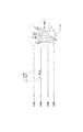
図11に、4本の指に刺激発生手段としてコイン型振動モータ10〜13を装着した場合の例を示す。
FIG. 11 shows an example in which coin-
以下では、刺激発生手段が、人体が知覚することができる力を発生している状態をオン状態、人体が知覚することができる力を発生していない状態をオフ状態と呼ぶ。特に刺激発生手段に振動モータを使用した場合には、偏心回転子の加速及び減速によりトルクを発生し、皮膚面内に水平な方向に人体が知覚することができる力が発生している状態をオン状態と呼ぶ。また、偏心回転子の加速及び減速によりトルクが発生しておらず、人体が知覚することができる力が発生していない状態をオフ状態と呼ぶ。 Hereinafter, a state in which the stimulus generation unit generates a force that can be perceived by the human body is referred to as an on state, and a state in which a force that can be perceived by the human body is not generated. In particular, when a vibration motor is used as the stimulus generating means, a torque is generated by acceleration and deceleration of the eccentric rotor, and a force that can be perceived by the human body in the horizontal direction is generated in the skin surface. Called the on state. A state in which no torque is generated by acceleration and deceleration of the eccentric rotor and no force that can be perceived by the human body is generated is called an off state.
2つ以上の刺激発生手段を備える例であっても、実施の形態1のようにオン状態とオフ状態を所定のサイクルで設定し、少なくとも2つの刺激発生手段におけるサイクルが異なる制御を行うことにより、ユーザが平面や物体表面を感じることができるようになる。 Even in an example including two or more stimulus generation means, the ON state and the OFF state are set in a predetermined cycle as in the first embodiment, and control is performed with different cycles in at least two stimulus generation means. The user can feel a plane or the object surface.
以下では、複数の振動モータの制御方法について例を挙げて説明する。 Hereinafter, a method for controlling a plurality of vibration motors will be described by way of example.
まず、図11では、振動モータ10から振動モータ13の順にオン状態となるように複数の振動モータを制御している。この制御により、人差し指から、中指、薬指、小指の順で皮膚面内方向に対して水平な方向に力が加わる。この結果、4本の指で平面に触れた感覚を生じることができる。特に、装着の並び順にオン状態にしていることから、図に示すように、仮想物体表面に対して手を動かしながら触る時に、このような制御を行うことが好適な実施である。
First, in FIG. 11, a plurality of vibration motors are controlled so that the
なお、図11では、振動モータ10から振動モータ13の順にオン状態にした後に再び、振動モータ10から振動モータ13の順にオン状態になるように制御しているが、実際の動作はこれに限らない。例えば、振動モータ10から振動モータ13の順に一度だけオン状態にするようにしても良い。
In FIG. 11, after the
また、図11では説明のため、全ての振動モータを動作させたが、常に全てを動作させる必要はなく、状況によって動作させる振動モータを選択しても良い。これらの図に示した以外の制御方法を用いても良いことは、以下の他の図の説明でも同様である。 Further, in FIG. 11, all the vibration motors are operated for the sake of explanation, but it is not always necessary to operate all the vibration motors, and the vibration motors to be operated may be selected depending on the situation. The control methods other than those shown in these figures may be used in the explanation of other figures below.
次に、図12では、図11とは逆に、振動モータ10から振動モータ13の順にオフ状態となるように複数の振動モータを制御している。この制御でも、図11の制御と同様の効果が得られる。
Next, in FIG. 12, in contrast to FIG. 11, the plurality of vibration motors are controlled so that the
また、次に図13では隣り合う振動モータを交互にオン状態とオフ状態になるように制御している。このような制御を行うことで、比較的手を動かさずに物体表面を触るときの感覚をユーザに知覚させることが期待できる。 In FIG. 13, the adjacent vibration motors are controlled so as to be alternately turned on and off. By performing such control, it can be expected that the user perceives the sensation of touching the object surface without moving the hand relatively.
また、図14では、振動モータのグループを形成し、交互にオン状態とオフ状態となるように制御している。図14のようなグループを形成して動作させることにより、複数の振動モータのトルクを合成することができ、比較的強い力で物体表面に触れる感覚をユーザに提示することができるようになる。 In FIG. 14, a group of vibration motors is formed and controlled so as to be alternately turned on and off. By forming and operating a group as shown in FIG. 14, the torques of a plurality of vibration motors can be combined, and a sense of touching the object surface with a relatively strong force can be presented to the user.
なお、グループの形成は、隣り合うもの同士に限定することなく、位置の離れた振動モータとグループを形成しても良い。図13の例は、図14のグループを作って動作する例の一形態と言える。また、グループの形成は、均等な数の振動モータで構成されるグループに限定されることなく、数に偏りのあるグループ形成でも良い。またさらに、図14ではグループの数は2つであるが、これに限定されることなく、2つ以上のグループを形成するようにしても良い。 Note that the formation of groups is not limited to adjacent ones, and groups may be formed with vibration motors at different positions. The example of FIG. 13 can be said to be one form of an example of creating and operating the group of FIG. Further, the formation of groups is not limited to a group composed of an equal number of vibration motors, and may be a group formation with a bias in number. Furthermore, in FIG. 14, the number of groups is two, but the present invention is not limited to this, and two or more groups may be formed.
また、上記の制御方法以外に、オン状態とオフ状態になる振動モータをランダムに選択する方法を用いても良い。 In addition to the control method described above, a method of randomly selecting a vibration motor to be turned on and off may be used.
また、目的の知覚を妨げない程度では、全ての振動モータがオン状態である時間や、全ての振動モータがオフ状態である時間が含まれても良い。 Further, as long as the target perception is not hindered, the time during which all vibration motors are in the on state and the time during which all vibration motors are in the off state may be included.
(実施の形態3)
本発明は、ディスプレイに視覚的に表示された仮想物体と合わせて使用することが好適である。ディスプレイには、液晶やプラズマ、CRT、プロジェクター、ヘッドマウントディスプレイ(HMD)などを用いることができる。
また、人体位置を検出する方法と合わせて、実際の人体位置と仮想物体の位置関係に応じて、物体表面に触れた感覚を提示しても良い。人体位置の検出方法としては、マーカとカメラを用いる方法や、人体形状を画像処理により判定する方法、磁気センサや加速度・角速度センサや地磁気センサなどを用いた手法など、どのような方法を用いても良い。
(Embodiment 3)
The present invention is preferably used in conjunction with a virtual object visually displayed on a display. As the display, liquid crystal, plasma, CRT, projector, head mounted display (HMD) or the like can be used.
In addition to the method of detecting the human body position, a sense of touching the object surface may be presented according to the positional relationship between the actual human body position and the virtual object. As a human body position detection method, any method such as a method using a marker and a camera, a method for determining a human body shape by image processing, a method using a magnetic sensor, an acceleration / angular velocity sensor, a geomagnetic sensor, or the like is used. Also good.
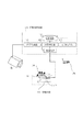
図15には、ディスプレイとしてヘッドマウントディスプレイ100を、位置検出手法としてマーカ108とカメラ109を用いた方法により構成した接触提示装置を示している。以下、図15の構成について説明する。
FIG. 15 shows a contact presentation apparatus configured by a method using the head mounted
人体2には、複数の振動モータ10を装着する。図15で、振動モータ10は指先に装着している例を示したが、人体のどの部分に装着してもよい。図15では、人体2の位置を取得するために、マーカ108とカメラ109と情報処理装置101内に位置検出部103を備えている。
A plurality of
記録装置106には、仮想物体の位置や外観、形状の情報が記録されている。位置判定部104では、位置検出部103により出力される人体の位置と、記録装置106に記録している仮想物体との位置関係を判定する。これにより、人体と仮想物体との距離や、接触の有無を判定する。なお、これらは公知の技術を用いればよいのでその詳細については省略する。
The recording device 106 records information on the position, appearance, and shape of the virtual object. The
そして、制御手段1では、位置判定部104の接触判定結果に基づいて、振動モータに振動の命令を行い、ユーザに仮想物体との接触を知覚させる。特に仮想物体表面に触れた場合に、振動モータ10で交互にトルクが発生するように制御手段1で制御を行い、ユーザに物体表面に触れた感覚を提示する。
Then, the
図15では、振動モータ10とマーカ108の位置は、人体の同一部位であるため、位置判定部104は人体と仮想物体の接触を判定するために、マーカ位置と仮想物体との接触を判定すればよい。また、実空間中での人体の形状を仮想空間中の人体モデルに当てはめ、仮想物体との接触判定を行う方法を用いても良い。この方法では例えば、人体の複数位置に設置したマーカと予め用意した人体モデルを使用し、位置検出部103で人体モデルの位置・姿勢を求める。
In FIG. 15, since the position of the
位置判定部104では、人体モデルの位置・姿勢を使用して人体と仮想物体との接触を判定するようにする。この方法によると、人体モデルを使用することで、マーカを装着していない人体部分についてもその位置を推定することができ、接触判定を行うことができるようになる。また、図15では、記録装置106に記録されている仮想物体を、画像出力部107を介して、ヘッドマウントディスプレイ100に表示している。ユーザは仮想物体110をヘッドマウントディスプレイ100により視覚的に把握しながら、振動モータ10による触覚情報を得ることができるようになる。
The
(実施の形態4)
以上の実施例では、ユーザに物体表面を知覚させる方法について説明した。従来の振動モータを使用した接触判定方法では、仮想物体との接触時に振動モータに振動を発生させ、ユーザに仮想物体との接触を知覚させたが、この従来の方法に、実施の形態3を組み合わせて使用しても良い。例えば、人体が仮想物体の表面位置に存在する場合には、上記実施の形態で説明したように、ユーザに物体表面を知覚させるように振動モータを制御する。そして、人体が仮想物体の深い位置に存在する場合には、振動モータを振動させることにより、ユーザに仮想物体との接触を知覚させる。
(Embodiment 4)
In the above embodiments, the method for causing the user to perceive the object surface has been described. In the contact determination method using the conventional vibration motor, the vibration motor is caused to vibrate at the time of contact with the virtual object, and the user is made to perceive the contact with the virtual object. You may use it in combination. For example, when the human body exists at the surface position of the virtual object, the vibration motor is controlled so that the user perceives the object surface as described in the above embodiment. And when a human body exists in the deep position of a virtual object, a user perceives contact with a virtual object by vibrating a vibration motor.
図16には、この制御の切り替えの例を説明する図を示す。図16には、複数の振動モータ10を人体2(指先)に皮膚面内方向に回転方向が平行になるように装着した状態と、仮想物体110との位置関係を示している。
FIG. 16 is a diagram illustrating an example of this control switching. FIG. 16 shows a positional relationship between the virtual object 110 and a state in which a plurality of
図16の中で、領域Iは仮想物体110と関係がなく離れた空間であり、この位置に人体が存在する場合には振動モータ10を動作させない。次に、領域IIは仮想物体110表面から所定の距離dの範囲である。この領域IIに人体が存在する場合には、ユーザに物体表面を知覚させるために、交互にトルクが発生するように振動モータ10を制御する。さらに、領域IIIは仮想物体110内部の範囲である。領域IIIに人体2が存在する場合には、振動モータ10を連続振動あるいは所定の振動パターンで振動させて、ユーザに振動刺激を与える。この振動刺激により、ユーザは自分の体が仮想物体110内部に侵入していると判定することができる。
In FIG. 16, a region I is a space that is not related to the virtual object 110, and the
(実施の形態5)
以上の実施の形態では、振動モータを指先に装着する例について説明したが、刺激発生手段の装着位置は指先に限定されることはない。
(Embodiment 5)
In the above embodiment, the example in which the vibration motor is mounted on the fingertip has been described. However, the mounting position of the stimulus generating means is not limited to the fingertip.
例えば、図17では複数の振動モータ10を手から腕の範囲に装着した例を示す。このような装着方法であっても、以上の実施例で説明した制御方法により、ユーザに物体表面を知覚させることができる。また、トルクを発生させる複数の振動モータは、仮想物体との接触位置や装着位置に基づいて適切に選択すればよい。
For example, FIG. 17 shows an example in which a plurality of
また、図18には、人体の全身に振動モータ10を装着した例を示したが、この場合についても同様である。
FIG. 18 shows an example in which the
なお、図17、図18においては、制御部などは省略してある。 In FIG. 17 and FIG. 18, the control unit and the like are omitted.
以上のように、刺激発生手段の装着位置には特に限定がないが、刺激発生手段の力が連続的に感じられるように、隣り合う刺激発生手段はある程度近傍に装着することが望ましい。最適な刺激発生手段間の距離は、人体部位によって異なる。 As described above, the mounting position of the stimulus generating means is not particularly limited, but it is desirable that the adjacent stimulus generating means be mounted in the vicinity to some extent so that the force of the stimulus generating means can be continuously felt. The optimal distance between the stimulus generating means varies depending on the human body part.
(実施の形態6)
以上の実施例では、刺激発生手段に振動モータを使用した例を主に説明したが、これ以外の手段を用いても良い。
(Embodiment 6)
In the above embodiment, the example in which the vibration motor is used as the stimulus generation means has been mainly described, but other means may be used.
すなわち、皮膚面内方向に水平な方向に力を発生できる手段であればどのような手段を用いても良い。その一つとして回転体で発生するトルクを用いることは既に記述した。振動モータ及び回転体の駆動方法については、電磁式に限定されることなく、どのような方法を用いても良い。 That is, any means may be used as long as it can generate a force in a direction horizontal to the skin in-plane direction. As described above, the torque generated by the rotating body is used as one of them. The driving method of the vibration motor and the rotating body is not limited to the electromagnetic type, and any method may be used.
また、トルクの発生方法として、偏心回転子または回転子の角速度を変化させる方法を説明したが、トルクの発生方法としては、式(2)に示すように慣性モーメントを時間的に変化させるようにしても良い。慣性モーメントは、 Further, as a method of generating torque, the method of changing the eccentric rotor or the angular velocity of the rotor has been described. However, as a method of generating torque, the moment of inertia is changed with time as shown in equation (2). May be. The moment of inertia is
![]()
![]()
で定義されるため、偏心回転子または回転子の質量や質点の中心軸からの距離を時間的に変化させることによりトルクが発生する。ここで、mは質点の質量、rは中心軸からの距離である。 Therefore, torque is generated by temporally changing the mass of the eccentric rotor or the rotor or the distance from the center axis of the mass point. Here, m is the mass of the mass point, and r is the distance from the central axis.
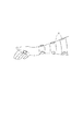
トルクを使用する以外の方法としては、図19に示すように、皮膚面内に水平な方向に平行移動する板状の物体190を刺激発生手段としても良い。刺激発生手段190は、電磁モータや超音波モータ、高分子アクチュエータ、静電アクチュエータ、形状記憶合金、空気圧制御、ピエゾ素子などのアクチュエータにより、水平方向に移動する。刺激発生手段190が皮膚面内に水平な方向に平行移動することで、皮膚には水平方向の力が加わる。 このような刺激発生手段190を複数備え、交互に駆動、停止を行うことで、ユーザに平面や物体表面の広がりを知覚させることができるようになる。
As a method other than using torque, as shown in FIG. 19, a plate-
(実施の形態7)
以上の実施例では、刺激発生手段を人体に装着する例について示したが、本発明の使用方法は、人体への装着に限定されることはない。例えば、マウスなどのポインティングデバイスや、ゲームコントローラなどの従来の入力装置などに複数の刺激発生手段を備え、物体表面をユーザに知覚させるようにしても良い。
(Embodiment 7)
In the above embodiment, the example in which the stimulus generating means is mounted on the human body has been shown. However, the usage method of the present invention is not limited to the mounting on the human body. For example, a pointing device such as a mouse or a conventional input device such as a game controller may be provided with a plurality of stimulus generating means so that the user can perceive the object surface.
1 制御手段
2 人体
10、11、12、13 振動モータ
20 円筒型振動モータ
21、31、41 偏心回転子
22、32、42 軸
30 コイン型振動モータ
40 回転体
41 回転子
100 ヘッドマウントディスプレイ
101 情報処理装置
102 記録装置
103 位置検出部
104 位置判定部
105 画像出力部
108 マーカ
109 カメラ
110 仮想物体
190 刺激発生手段
DESCRIPTION OF
Claims (12)
少なくとも2つ以上の刺激発生手段と、
前記刺激発生手段のオン状態とオフ状態を所定のサイクルで設定し、少なくとも2つの刺激発生手段における前記サイクルが異なる制御を行う制御手段と
を備えたことを特徴とする接触提示装置。 A contact presentation device for presenting a predetermined perception to a human body,
At least two or more stimulus generating means;
A contact presentation device comprising: control means for setting the on state and the off state of the stimulus generation means in a predetermined cycle, and performing control in which the cycles of the at least two stimulus generation means are different.
前記制御手段は、前記表示装置に表示される仮想物体と前記刺激発生手段の位置関係に基づいて制御することを特徴とする請求項1に記載の接触提示装置。 A display device for visually displaying a virtual object;
The contact presentation device according to claim 1, wherein the control unit performs control based on a positional relationship between a virtual object displayed on the display device and the stimulus generation unit.
人体と仮想物体の接触を判定する接触判定部を更に備え、
前記制御手段は、前記接触判定部の判定結果に基づいて制御することを特徴とする請求項1に記載の接触提示装置。 A position detector for detecting the position of the human body;
A contact determination unit for determining contact between the human body and the virtual object;
The contact presentation apparatus according to claim 1, wherein the control unit performs control based on a determination result of the contact determination unit.
少なくとも2つ以上の刺激発生手段と、
オン状態とオフ状態を所定のサイクルで設定し、前記仮想物体の表面の所定の範囲内に人体が位置するときに、少なくとも2つの刺激発生手段における前記サイクルが異なる制御を行う制御手段と
を備えたことを特徴とする接触提示装置。 A contact presentation device for presenting a virtual object and a predetermined perception to a human body,
At least two or more stimulus generating means;
Control means for setting an on state and an off state in a predetermined cycle, and performing control in which the cycle in at least two stimulus generation means is different when a human body is located within a predetermined range of the surface of the virtual object. A contact presentation device characterized by that.
少なくとも2つ以上の刺激発生手段と、
人体に設置された少なくとも2つ以上の刺激発生手段の内、少なくとも一つの刺激発生手段をオン状態にし、少なくとも1つの刺激発生手段をオフ状態にして、オン状態またはオフ状態である刺激発生手段を順次変更する制御を行う制御手段と
を備えたことを特徴とする接触提示装置。 A contact presentation device for presenting a predetermined perception to a human body,
At least two or more stimulus generating means;
Among the at least two or more stimulus generating means installed in the human body, at least one stimulus generating means is turned on, at least one stimulus generating means is turned off, and the stimulus generating means that is on or off is provided. A contact presenting device comprising: control means for performing control to change sequentially.
前記刺激発生手段のオン状態とオフ状態を所定のサイクルで設定する設定工程と、
人体に設置された少なくとも2つの刺激発生手段における前記サイクルが異なる制御を行う制御工程と
を備えたことを特徴とする接触提示方法。 A contact presentation method for presenting a predetermined perception to a human body,
A setting step of setting an on state and an off state of the stimulus generating means in a predetermined cycle;
And a control step of performing control with different cycles in at least two stimulus generating means installed in a human body.
オン状態とオフ状態を所定のサイクルで設定する設定工程と、
前記仮想物体の表面の所定の範囲内に人体が位置するときに、人体に設置された少なくとも2つの刺激発生手段における前記サイクルが異なる制御を行う制御工程と
を備えたことを特徴とする接触提示方法。 A contact presentation method for presenting a virtual object and a predetermined perception to a human body,
A setting process for setting the on state and the off state in a predetermined cycle;
And a control step for performing different control of the cycle in at least two stimulus generating means installed on the human body when the human body is located within a predetermined range of the surface of the virtual object. Method.
少なくとも2つ以上の刺激発生手段と、
人体に設置された少なくとも2つ以上の刺激発生手段の内、少なくとも一つの刺激発生手段をオン状態にし、少なくとも1つの刺激発生手段をオフ状態にする第1の制御工程と、
所定時間経過後に、オン状態またはオフ状態である刺激発生手段を順次変更する第2の制御工程と
を備えたことを特徴とする接触提示方法。 A contact presentation method for presenting a predetermined perception to a human body,
At least two or more stimulus generating means;
A first control step of turning on at least one stimulus generating means among at least two or more stimulus generating means installed in a human body and turning off at least one stimulus generating means;
And a second control step of sequentially changing the stimulus generating means in the on state or the off state after a predetermined time has elapsed.
Priority Applications (4)
| Application Number | Priority Date | Filing Date | Title |
|---|---|---|---|
| JP2006166205A JP2007331066A (en) | 2006-06-15 | 2006-06-15 | Contact presenting device and method |
| US11/760,403 US20070290988A1 (en) | 2006-06-15 | 2007-06-08 | Feel presenting device and method |
| DE602007009337T DE602007009337D1 (en) | 2006-06-15 | 2007-06-15 | Tastfeedbackvorrichtung |
| EP07110393A EP1868063B1 (en) | 2006-06-15 | 2007-06-15 | Tactile - feedback device |
Applications Claiming Priority (1)
| Application Number | Priority Date | Filing Date | Title |
|---|---|---|---|
| JP2006166205A JP2007331066A (en) | 2006-06-15 | 2006-06-15 | Contact presenting device and method |
Publications (2)
| Publication Number | Publication Date |
|---|---|
| JP2007331066A true JP2007331066A (en) | 2007-12-27 |
| JP2007331066A5 JP2007331066A5 (en) | 2009-07-30 |
Family
ID=38326288
Family Applications (1)
| Application Number | Title | Priority Date | Filing Date |
|---|---|---|---|
| JP2006166205A Pending JP2007331066A (en) | 2006-06-15 | 2006-06-15 | Contact presenting device and method |
Country Status (4)
| Country | Link |
|---|---|
| US (1) | US20070290988A1 (en) |
| EP (1) | EP1868063B1 (en) |
| JP (1) | JP2007331066A (en) |
| DE (1) | DE602007009337D1 (en) |
Cited By (1)
| Publication number | Priority date | Publication date | Assignee | Title |
|---|---|---|---|---|
| JP2009175777A (en) * | 2008-01-21 | 2009-08-06 | Canon Inc | Information processing apparatus and method |
Families Citing this family (26)
| Publication number | Priority date | Publication date | Assignee | Title |
|---|---|---|---|---|
| EP2210162B9 (en) * | 2007-11-19 | 2019-01-23 | Nokia Technologies Oy | Input device |
| US9927873B2 (en) * | 2009-03-12 | 2018-03-27 | Immersion Corporation | Systems and methods for using textures in graphical user interface widgets |
| US9696803B2 (en) | 2009-03-12 | 2017-07-04 | Immersion Corporation | Systems and methods for friction displays and additional haptic effects |
| US9874935B2 (en) | 2009-03-12 | 2018-01-23 | Immersion Corporation | Systems and methods for a texture engine |
| US9746923B2 (en) | 2009-03-12 | 2017-08-29 | Immersion Corporation | Systems and methods for providing features in a friction display wherein a haptic effect is configured to vary the coefficient of friction |
| US10564721B2 (en) * | 2009-03-12 | 2020-02-18 | Immersion Corporation | Systems and methods for using multiple actuators to realize textures |
| US10007340B2 (en) * | 2009-03-12 | 2018-06-26 | Immersion Corporation | Systems and methods for interfaces featuring surface-based haptic effects |
| WO2011062895A2 (en) * | 2009-11-17 | 2011-05-26 | Immersion Corporation | Systems and methods for increasing haptic bandwidth in an electronic device |
| US20110148885A1 (en) * | 2009-12-18 | 2011-06-23 | Electronics And Telecommunications Research Institute | Apparatus and method for editing animation data of virtual object utilizing real model |
| US20120302868A1 (en) * | 2011-05-24 | 2012-11-29 | Canon Kabushiki Kaisha | Texture stimulus presenting apparatus, magnetic resonance imaging apparatus and magnetoencephalograph including the same, and brain function measuring method |
| US20140214631A1 (en) * | 2013-01-31 | 2014-07-31 | Intermec Technologies Corporation | Inventory assistance device and method |
| US9619029B2 (en) * | 2013-11-14 | 2017-04-11 | Immersion Corporation | Haptic trigger control system |
| US9164587B2 (en) | 2013-11-14 | 2015-10-20 | Immersion Corporation | Haptic spatialization system |
| KR101578345B1 (en) * | 2014-09-03 | 2015-12-17 | 재단법인 실감교류인체감응솔루션연구단 | Apparatus for generating force feedback |
| WO2016049284A1 (en) | 2014-09-24 | 2016-03-31 | Taction Technology Inc. | Systems and methods for generating damped electromagnetically actuated planar motion for audio-frequency vibrations |
| US10185396B2 (en) | 2014-11-12 | 2019-01-22 | Immersion Corporation | Haptic trigger modification system |
| US9936273B2 (en) | 2015-01-20 | 2018-04-03 | Taction Technology, Inc. | Apparatus and methods for altering the appearance of wearable devices |
| JP5831893B1 (en) * | 2015-05-07 | 2015-12-09 | 立 寺坂 | Aircraft remote control system |
| US10055019B2 (en) | 2015-05-20 | 2018-08-21 | Sony Interactive Entertainment Inc. | Electromagnet-laden glove for haptic pressure feedback |
| US10573139B2 (en) | 2015-09-16 | 2020-02-25 | Taction Technology, Inc. | Tactile transducer with digital signal processing for improved fidelity |
| EP3349917A4 (en) | 2015-09-16 | 2019-08-21 | Taction Technology, Inc. | Apparatus and methods for audio-tactile spatialization of sound and perception of bass |
| WO2017178862A1 (en) * | 2016-04-11 | 2017-10-19 | Berkovs Boriss | Method for modeling and simulating physical effect in interactive simulators and electronic games, system for implementing the same and method for calibrating the system |
| US10318004B2 (en) * | 2016-06-29 | 2019-06-11 | Alex Shtraym | Apparatus and method for providing feedback at a predetermined distance |
| US10845876B2 (en) * | 2017-09-27 | 2020-11-24 | Contact Control Interfaces, LLC | Hand interface device utilizing haptic force gradient generation via the alignment of fingertip haptic units |
| KR102045891B1 (en) * | 2018-04-05 | 2019-11-18 | 포항공과대학교 산학협력단 | Apparatus and method for providing a virtual texture |
| US11531391B2 (en) * | 2020-10-09 | 2022-12-20 | Contact Control Interfaces, LLC | Tendon driven exoskeleton tightening mechanism |
Citations (5)
| Publication number | Priority date | Publication date | Assignee | Title |
|---|---|---|---|---|
| JPH0890458A (en) * | 1994-09-21 | 1996-04-09 | Olympus Optical Co Ltd | Tactile sense transmitting device |
| JPH0990867A (en) * | 1995-09-27 | 1997-04-04 | Olympus Optical Co Ltd | Tactile sensing presentation device |
| JP2000501033A (en) * | 1995-11-30 | 2000-02-02 | ヴァーチャル テクノロジーズ インコーポレイテッド | Human / machine interface with tactile feedback |
| JP2004029999A (en) * | 2002-06-24 | 2004-01-29 | Matsushita Electric Ind Co Ltd | Tactile force display hand and its manufacturing method |
| JP2005190465A (en) * | 2003-11-20 | 2005-07-14 | National Institute Of Advanced Industrial & Technology | Tactile force information display system and method |
Family Cites Families (7)
| Publication number | Priority date | Publication date | Assignee | Title |
|---|---|---|---|---|
| US5631861A (en) * | 1990-02-02 | 1997-05-20 | Virtual Technologies, Inc. | Force feedback and texture simulating interface device |
| US6028593A (en) * | 1995-12-01 | 2000-02-22 | Immersion Corporation | Method and apparatus for providing simulated physical interactions within computer generated environments |
| US6087942A (en) * | 1998-05-18 | 2000-07-11 | Jb Research, Inc. | Tactile alert and massaging system |
| WO2002027705A1 (en) * | 2000-09-28 | 2002-04-04 | Immersion Corporation | Directional tactile feedback for haptic feedback interface devices |
| US20030011252A1 (en) * | 2001-07-14 | 2003-01-16 | Edwin Langberg | Roto-oscillator |
| JP2003285009A (en) * | 2002-03-25 | 2003-10-07 | Samsung Electro Mech Co Ltd | Coin type vibration motor |
| US7283120B2 (en) * | 2004-01-16 | 2007-10-16 | Immersion Corporation | Method and apparatus for providing haptic feedback having a position-based component and a predetermined time-based component |
-
2006
- 2006-06-15 JP JP2006166205A patent/JP2007331066A/en active Pending
-
2007
- 2007-06-08 US US11/760,403 patent/US20070290988A1/en not_active Abandoned
- 2007-06-15 EP EP07110393A patent/EP1868063B1/en not_active Expired - Fee Related
- 2007-06-15 DE DE602007009337T patent/DE602007009337D1/en active Active
Patent Citations (5)
| Publication number | Priority date | Publication date | Assignee | Title |
|---|---|---|---|---|
| JPH0890458A (en) * | 1994-09-21 | 1996-04-09 | Olympus Optical Co Ltd | Tactile sense transmitting device |
| JPH0990867A (en) * | 1995-09-27 | 1997-04-04 | Olympus Optical Co Ltd | Tactile sensing presentation device |
| JP2000501033A (en) * | 1995-11-30 | 2000-02-02 | ヴァーチャル テクノロジーズ インコーポレイテッド | Human / machine interface with tactile feedback |
| JP2004029999A (en) * | 2002-06-24 | 2004-01-29 | Matsushita Electric Ind Co Ltd | Tactile force display hand and its manufacturing method |
| JP2005190465A (en) * | 2003-11-20 | 2005-07-14 | National Institute Of Advanced Industrial & Technology | Tactile force information display system and method |
Cited By (1)
| Publication number | Priority date | Publication date | Assignee | Title |
|---|---|---|---|---|
| JP2009175777A (en) * | 2008-01-21 | 2009-08-06 | Canon Inc | Information processing apparatus and method |
Also Published As
| Publication number | Publication date |
|---|---|
| US20070290988A1 (en) | 2007-12-20 |
| EP1868063A3 (en) | 2008-06-25 |
| EP1868063B1 (en) | 2010-09-22 |
| EP1868063A2 (en) | 2007-12-19 |
| DE602007009337D1 (en) | 2010-11-04 |
Similar Documents
| Publication | Publication Date | Title |
|---|---|---|
| JP2007331066A (en) | Contact presenting device and method | |
| JP7366961B2 (en) | Method and device for driving illusionary tactile force sense | |
| US11287892B2 (en) | Haptic information presentation system | |
| US10936072B2 (en) | Haptic information presentation system and method | |
| JP4921113B2 (en) | Contact presentation apparatus and method | |
| Choi et al. | Vibrotactile display: Perception, technology, and applications | |
| JP5616317B2 (en) | Apparatus, system, and method for providing tactile sensation | |
| JP2008123431A (en) | Contact presenting device and method | |
| JP2008257295A (en) | Method for presenting tactile stimulus | |
| JP2017073100A (en) | Tactile and force information providing system | |
| JP2019075096A (en) | Haptic effects with multiple peripheral devices | |
| JP6955229B2 (en) | Tactile information presentation system | |
| JP2023164717A (en) | Tactile force sense information presentation system | |
| JP2008134697A (en) | Contact presentation apparatus | |
| JP2006351042A (en) | Mobile apparatus having tactile feedback function | |
| Niwa et al. | Fingernail-mounted display of attraction force and texture | |
| WO2019043787A1 (en) | Vibration control device | |
| Aichelburg | Haptic Actuator Technology for Virtual Environment Interfaces |
Legal Events
| Date | Code | Title | Description |
|---|---|---|---|
| A521 | Request for written amendment filed |
Free format text: JAPANESE INTERMEDIATE CODE: A523 Effective date: 20090612 |
|
| A621 | Written request for application examination |
Free format text: JAPANESE INTERMEDIATE CODE: A621 Effective date: 20090612 |
|
| RD04 | Notification of resignation of power of attorney |
Free format text: JAPANESE INTERMEDIATE CODE: A7424 Effective date: 20100201 |
|
| RD01 | Notification of change of attorney |
Free format text: JAPANESE INTERMEDIATE CODE: A7421 Effective date: 20100630 |
|
| A977 | Report on retrieval |
Free format text: JAPANESE INTERMEDIATE CODE: A971007 Effective date: 20110719 |
|
| A131 | Notification of reasons for refusal |
Free format text: JAPANESE INTERMEDIATE CODE: A131 Effective date: 20110726 |
|
| A521 | Request for written amendment filed |
Free format text: JAPANESE INTERMEDIATE CODE: A523 Effective date: 20110915 |
|
| A02 | Decision of refusal |
Free format text: JAPANESE INTERMEDIATE CODE: A02 Effective date: 20120117 |