JP2007328126A - An image forming apparatus, a developing apparatus, and a developer replenishing method. - Google Patents
An image forming apparatus, a developing apparatus, and a developer replenishing method. Download PDFInfo
- Publication number
- JP2007328126A JP2007328126A JP2006159138A JP2006159138A JP2007328126A JP 2007328126 A JP2007328126 A JP 2007328126A JP 2006159138 A JP2006159138 A JP 2006159138A JP 2006159138 A JP2006159138 A JP 2006159138A JP 2007328126 A JP2007328126 A JP 2007328126A
- Authority
- JP
- Japan
- Prior art keywords
- developer
- image
- density
- threshold
- toner
- Prior art date
- Legal status (The legal status is an assumption and is not a legal conclusion. Google has not performed a legal analysis and makes no representation as to the accuracy of the status listed.)
- Withdrawn
Links
Images


Landscapes
- Dry Development In Electrophotography (AREA)
- Control Or Security For Electrophotography (AREA)
Abstract
【課題】現像装置に対して従来よりも高精度に現像剤を補給する。
【解決手段】画像形成装置は、形成される画像についての印字比率に基づいて、画像を形成する際に消費される現像剤の消費量を推定する推定手段と、画像ごとに推定された消費量を積算する積算手段とを含む。また、本装置は、積算された消費量が閾値を超えたか否かを補給時期ごとに判定する判定手段と、積算された消費量が閾値を超えると、閾値に相当する一定量の現像剤を現像容器へ補給する補給手段とを含む。とりわけ、本装置は、現像容器に収納されている現像剤の劣化の程度を推測する推測手段と、現像剤の劣化の程度に応じて閾値を調整する調整手段とを含む。
【選択図】図1A developer is supplied to a developing device with higher accuracy than before.
An image forming apparatus estimates an amount of developer consumed when forming an image based on a print ratio of an image to be formed, and a consumption estimated for each image. Integrating means for integrating. In addition, the apparatus includes a determination unit that determines whether or not the accumulated consumption exceeds a threshold value for each replenishment period, and a fixed amount of developer corresponding to the threshold when the accumulated consumption exceeds the threshold value. Replenishing means for replenishing the developing container. In particular, the apparatus includes an estimation unit that estimates the degree of deterioration of the developer stored in the developer container, and an adjustment unit that adjusts the threshold according to the degree of deterioration of the developer.
[Selection] Figure 1
Description
本発明は、現像剤を用いて画像を形成する画像形成技術に関する。 The present invention relates to an image forming technique for forming an image using a developer.
トナーなどの現像剤を使用する画像形成装置では、画像形成により消費された分だけ現像器へトナーを補給する必要がある。また、形成される画像の品質を維持するには、現像器内のトナー量が略一定となるようにトナーを補給する必要もある。 In an image forming apparatus that uses a developer such as toner, it is necessary to replenish toner to the developing device by the amount consumed by image formation. Further, in order to maintain the quality of the formed image, it is necessary to replenish the toner so that the toner amount in the developing device becomes substantially constant.
特許文献1や特許文献2によれば、ビデオカウントを利用したトナー補給方式が提案されている。この方式によれば、画素ごとにビデオ信号の出力レベルを積算することで画像の印字比率が求められ、印字比率に応じた量のトナーが補給される。
しかしながら、上記のトナー補給方式では、ベタ画像などの高い印字比率の画像が形成されたときなどに以下のような問題が生じうる。すなわち、高い印字比率の画像が形成されると大量にトナーが消費されるため、それに伴って補給されるトナー量も多くなる。現像容器内へ大量の新しいトナーが補給されると、トナーへの帯電付与作業が追いつかなくなり、帯電不足が発生する。帯電不足が発生すれば、本来印字しない白部(未露光部)においてトナーが現像されてしまい、地汚れのように紙上に現れる画像不良(以下、“かぶり”と言う)、濃度ムラまたはトナー飛散などの好ましくない現象が発生しうる。このような問題は、現像装置の使用度合いが進んで各パーツが劣化してきたり、高温高湿環境によりトナーの帯電性が低下したりしているときに、とりわけ顕在化しやすい。 However, the above-described toner replenishment method may cause the following problems when an image with a high printing ratio such as a solid image is formed. That is, since a large amount of toner is consumed when an image with a high printing ratio is formed, the amount of toner replenished is increased accordingly. When a large amount of new toner is replenished into the developing container, the operation of imparting charge to the toner cannot catch up, resulting in insufficient charging. If insufficient charging occurs, the toner is developed in a white portion (unexposed portion) that is not originally printed, and an image defect (hereinafter referred to as “fogging”), density unevenness, or toner scattering that appears on the paper like background stains. Undesirable phenomena such as can occur. Such a problem is particularly apparent when the degree of use of the developing device is advanced and each part is deteriorated or the chargeability of the toner is lowered due to a high temperature and high humidity environment.
なお、かぶりを抑制するために、一回あたりの補給量を少なくする方法も考えられる。しかしながらこの方法では、現像容器内の現像剤が急激に減少し、白抜け画像が形成されてしまうおそれがある。また、現像剤の急激な減少を防ぐために、現像剤の補給作業を頻繁に実行すれば、画像形成を実行できないダウンタイムが増加してしまい好ましくない。 In order to suppress fogging, a method of reducing the replenishment amount per time is also conceivable. However, in this method, the developer in the developing container is rapidly reduced, and there is a possibility that a white image is formed. Further, if the developer replenishment operation is frequently performed in order to prevent a rapid decrease in the developer, the downtime during which image formation cannot be performed increases, which is not preferable.
そこで、本発明は、現像装置の帯電付与能力を超えるほどの大量のトナーが一度に補給されることを抑制することで、かぶり、濃度ムラまたはトナー飛散などの好ましくない現象を抑制することを目的とする。 Therefore, the present invention aims to suppress undesirable phenomena such as fogging, density unevenness, and toner scattering by suppressing a large amount of toner exceeding the charge imparting capability of the developing device at once. And
本発明は、形成される画像についての印字比率に基づいて、画像を形成する際に消費される現像剤の消費量を推定する推定手段と、画像ごとに推定された消費量を積算する積算手段とを含む。また、本発明は、積算された消費量が閾値を超えたか否かを判定する判定手段と、積算された消費量が閾値を超えると、閾値に相当する一定量の現像剤を現像容器へ補給する補給手段とを含む。とりわけ、本発明は、現像容器に収納されている現像剤の劣化の程度を推測する推測手段と、現像剤の劣化の程度に応じて閾値を調整する調整手段とを含むことを特徴とする。 The present invention relates to an estimation unit that estimates a consumption amount of a developer that is consumed when an image is formed based on a printing ratio for an image to be formed, and an integration unit that accumulates the consumption amount estimated for each image. Including. Further, the present invention provides a determination means for determining whether or not the accumulated consumption exceeds a threshold value, and when the accumulated consumption exceeds the threshold value, a certain amount of developer corresponding to the threshold value is supplied to the developing container. Replenishment means. In particular, the present invention is characterized by including estimation means for estimating the degree of deterioration of the developer stored in the developer container, and adjustment means for adjusting the threshold according to the degree of deterioration of the developer.
本発明によれば、現像剤の劣化の程度に応じて、1回で補給される現像剤の量を調整することことができる。これにより、現像装置の帯電付与能力を超えるほどの大量のトナーが一度に補給されることを抑制することができる。すなわち、かぶり、濃度ムラまたはトナー飛散などの好ましくない現象を抑制することが可能となる。 According to the present invention, the amount of developer to be replenished at one time can be adjusted according to the degree of deterioration of the developer. Thereby, it is possible to prevent a large amount of toner exceeding the charge imparting capability of the developing device from being replenished at a time. That is, undesirable phenomena such as fogging, density unevenness, and toner scattering can be suppressed.
以下に本発明の一実施形態を示す。もちろん以下で説明される個別の実施形態は、本発明の上位概念、中位概念および下位概念など種々の概念を理解するために役立つであろう。また、本発明の技術的範囲は、特許請求の範囲によって確定されるのであって、以下の個別の実施形態によって限定されるわけではない。 An embodiment of the present invention is shown below. Of course, the individual embodiments described below will be helpful in understanding various concepts such as the superordinate concept, intermediate concept and subordinate concept of the present invention. Further, the technical scope of the present invention is determined by the scope of the claims, and is not limited by the following individual embodiments.
[実施形態1]
図1は、本実施形態に係る画像形成装置の概略構成を示す断面図である。像担持体(以下、感光ドラムと称す。)1は、ドラム状の電子写真感光体である。帯電装置2は、感光ドラム1の表面を一様に帯電する。露光装置3は、画像情報に対応したレーザ光を感光ドラム1の表面に照射する。これにより、感光ドラム1上に静電潜像が形成される。
[Embodiment 1]
FIG. 1 is a cross-sectional view illustrating a schematic configuration of an image forming apparatus according to the present embodiment. An image carrier (hereinafter referred to as a photosensitive drum) 1 is a drum-shaped electrophotographic photosensitive member. The
現像装置4は、現像剤を補給する現像剤補給装置(以下、トナーホッパーと称す。)5と、現像剤の消費量に応じてトナーホッパー5からの現像剤の補給量を制御する制御ユニット10を備える。制御ユニット10としては、例えば、CPUや専用の電気回路を用いることができる。制御ユニット10は、画像形成装置本体に設けられていてもよいし、現像装置4に設けられていてもよい。また、制御ユニット10の各機能が、画像形成装置本体と現像装置4とに分離されて設けられていてもよい。この場合、画像形成装置本体に設けられた第1の制御ユニットと、現像装置4に設けられた第2の制御ユニットが情報を交換し合うことで、本実施形態に係るトナー補給制御を実行することになる。
The developing device 4 includes a developer replenishing device (hereinafter referred to as a toner hopper) 5 that replenishes the developer, and a
本実施形態では、便宜上、感光ドラム1の帯電電荷を負極性とする。画像情報に対応した静電潜像は、露光装置3からのレーザ光による露光によって、負極性の帯電電荷が減衰した部分に形成される。静電潜像は、感光ドラム1の回転に伴って、現像装置4が供給する現像剤(例:トナー)により可視化されてトナー像となる。なお、本実施形態の現像方式としては、反転現像方式が採用されている。そのため、帯電電荷と同極性(負極性)のトナーが、感光ドラム1上で帯電電荷が減衰した部分(画像部)に付着する。
In this embodiment, for the sake of convenience, the charged charge of the
一方、不図示のカセットに収納された記録媒体Pは、給紙ローラ9によって感光ドラム1と、転写ローラ6とが当接する転写領域へと搬送される。感光ドラム1上のトナー像と記録媒体Pとが転写領域に至ると、転写領域に形成される転写電界により、トナー像が記録媒体P上に転写される。記録媒体Pに担持された未定着トナー像は、定着装置8の備えるヒートローラ8aによる加熱、および、加圧ローラ8bによる加圧を受けて、記録媒体P上に画像として定着される。トナー像の転写を終了した感光ドラム1は、ブレード状のクリーニング装置7によって、残留トナーが除去される。
On the other hand, the recording medium P stored in a cassette (not shown) is conveyed by a paper feed roller 9 to a transfer area where the
濃度検出センサ17は、感光ドラム1に形成されたトナーの濃度を検出するセンサである。なお、中間転写ベルトなどの中間転写体(像担持体の一種)を使用する画像形成装置では、濃度検出センサ17が、中間転写体上に形成されたトナーの濃度を検出してもよい。また、濃度検出センサ17は、記録媒体P上に形成されたトナーの濃度を検出してもよい。なお、検出されたトナーの濃度は、現像装置4に収納されているトナーの劣化の程度を把握するために役に立つ情報の1つである。
The
[現像装置の概要]
図2は、本実施形態に係る現像装置の概略構成を示す断面図である。現像装置4は、画像形成装置本体に対して着脱可能に構成されている。この構成によれば、現像装置の交換を容易に行うことができる。なお、現像装置4と感光ドラム1などを一体化して、プロセスカートリッジとしてもよい。
[Overview of development equipment]
FIG. 2 is a cross-sectional view illustrating a schematic configuration of the developing device according to the present embodiment. The developing device 4 is configured to be detachable from the image forming apparatus main body. According to this configuration, the developing device can be easily replaced. The developing device 4 and the
現像ローラ11は、トナーを担持搬送し、感光ドラム1上の静電潜像を現像する現像剤担持体である。なお、トナーは、現像ローラ11と供給ローラ13との摺擦により帯電される。ブレード12は、供給ローラ13により供給されたトナーを規制して感光ドラム1上にトナーの層を形成する現像剤規制ユニットである。供給ローラ13は、現像ローラ11へトナーを供給する現像剤供給ユニットである。なお、本実施形態で、供給ローラ13は、現像剤の供給ユニット及び回収ユニットとして機能するが、本発明はこれに限定されるものではない。すなわち、現像剤供給ユニットと現像剤回収ユニットとが、別個に設けられてもよい。撹拌パドル14は、トナーホッパー5から補給されたトナーと現像容器16内のトナーとを混合するために回動する現像剤撹拌ユニットである。
The developing roller 11 is a developer carrying member that carries and conveys toner and develops the electrostatic latent image on the
残量検知センサ15は、現像容器16内のトナーの残量を検知する現像剤残量検知ユニットである。残量検知センサ15は、発光素子からなる発光部15a、光が透過する窓部15b、受光素子からなる受光部15cを有する。そして、撹拌パドル14の回転に伴ってトナーの剤面が変化する際に、撹拌パドル14が一回転する時間に対する光の透過時間の割合を測定し、撹拌領域における剤面の高さ情報を得ている。それゆえ、残量検知センサ15は、剤面の高さを検知するセンサであると理解されてもよい。
The remaining
残量検知センサ15は、予め定められた第1のレベルεから、第2のレベルδまでを検出可能範囲としている。この検出可能範囲がトナー面の制御レベルに対応している。第1のレベルεは、形成される画像の濃度が薄くなりすぎることが原因で発生する画質の劣化(例:濃度ムラ)が生じない程度のレベルに設定されることが望ましい。また、第2のレベルδは、残量の過多が原因で発生する画質の劣化(例:かぶり、ぼた落ち)が生じない程度のレベルに設定されることが望ましい。各レベルは、画像形成装置ごとに経験的に決定されることになろう。
The remaining
現像容器16は、第1の容器であるトナーホッパー5から供給されたトナーを収納する第2の容器である。トナーホッパー5内には、トナーホッパー5から現像容器16にトナーを補給するための補給ローラ53と、トナーホッパー5内のトナーをほぐすための撹拌部材54が配置されている。そして、制御ユニット10からの補給指令により、所定の駆動時間当たり一定量のトナーを現像装置4に補給できるように構成されている。
The developing
現像装置4には、不揮発性の記憶装置40が設けられている。現像装置4が画像形成装置から取り外されると、記憶装置40に対する画像形成装置本体からの電力の供給が停止されるが、記憶装置40は、引き続き記憶内容を保持することができる。記憶装置40には、後述する各種の情報が保持される。例えば、閾値の調整の可否を決定するために、記録媒体または像担持体上に形成された基準となる現像剤像の濃度と比較される基準濃度(理想的な濃度値)が記憶装置40に記憶されていてもよい。基準濃度は、工場出荷時に記憶装置40に記憶されていてもよいし、現像装置4の使用初期において取得されて、記憶装置40に記憶されていてもよい。なお、記憶装置40は、非接触式のメモリタグ(ICタグ、RFIDタグ)などであってもよい。
The developing device 4 is provided with a
[制御ユニットの概要]
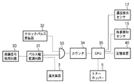
図3は、実施形態に係る制御ユニットの一例を示す図である。画像信号処理回路30は、静電潜像の元となる画像データを画像信号に変換する回路である。パルス幅変調回路31は、画像信号に応じて、画素ごとのレベルに対応した幅(時間長)のレーザ駆動パルスを発生する。レーザ駆動パルスは、露光装置3とANDゲート33に供給される。ANDゲート33の他端には、クロックパルス発振器32が接続されている。
[Overview of control unit]
FIG. 3 is a diagram illustrating an example of a control unit according to the embodiment. The image
カウンタ34は、画像の印字比率に対応するビデオ信号をカウントする係数回路である。CPU35は、カウントされた値に応じて画像の印字比率を決定し、さらに、印字比率に基づいて、現像容器16に収納されている現像剤の消費量を推定する。CPU35は、推定された消費量に応じてトナーホッパー5における現像剤の補給量を制御する。
The
とりわけ、CPU35は、現像剤が消費されたからといってすぐに現像剤を補給することはなく、消費量の積算値が閾値を超えると、閾値に相当する分の現像剤を補給する。CPU35は、ベタ画像を形成するときの現像剤の消費量である最大消費量よりも小さく、かつ、補給された現像剤によって現像容器内の現像剤に帯電不足が生じないように、閾値を調整する。具体的には、CPU35は、記録媒体または像担持体上に形成された基準となる現像剤像の濃度を濃度検出センサ17により検出させ、検出された濃度したがって、現像剤の劣化の程度を推測する。そして、CPU35は、推測された劣化の程度に応じて閾値を調整する。
In particular, the
図4は、実施形態に係るビデオカウント方式の原理を説明するための模式図である。図4(a)に示すように、パルス幅変調回路31は、相対的に高濃度の画素画像信号に対して、相対的に幅の広いレーザ駆動パルスWを生成する。また、パルス幅変調回路31は、相対的に低濃度の画素画像信号に対して、相対的に幅の狭いレーザ駆動パルスSを生成する。さらに、パルス幅変調回路31は、相対的に中濃度の画素画像信号に対して、中間の幅のレーザ駆動バルスIを生成する。
FIG. 4 is a schematic diagram for explaining the principle of the video count method according to the embodiment. As shown in FIG. 4A, the pulse
パルス幅変調回路31から出力されたレーザ駆動パルスは露光装置3に供給される。露光装置3は、パルス幅に対応する時間だけ半導体レーザを発光させる。したがって、半導体レーザは高濃度画素に対してはより長い時間にわたり駆動され、低濃度画素に対してはより短い時間にわたり駆動される。そのため、感光ドラム1は、高濃度画素に対しては主走査方向においてより長い範囲が露光され、低濃度画素に対しては主走査方向においてより短い範囲が露光される。つまり、画素の濃度に対応して静電潜像のドットサイズが異なることになる。したがって、高濃度画素に対するトナー消費量は低濃度画素に対するトナー消費量よりも多くなる。なお、図4(d)は、低、中、高濃度画素の静電潜像の形状L、M、Hを模式的にそれぞれ示した。
The laser driving pulse output from the pulse
図4(b)は、ANDゲート33の他端に入力されるクロックパルスが示されている。クロックパルスは、クロックパルス発振器32により生成されたものである。図4(c)が示すように、ANDゲート33からは、レーザ駆動パルスS、I、Wの各々のパルス幅に対応した数のクロックパルス、すなわち、各画素の濃度に対応した数のクロックパルスが出力される。クロックパルス数は、画像ごとにカウンタ34によって積算される。CPU35は、カウンタ34の積算値(ビデオカウント値またはピクセルカウント数)に応じて、画像印字比率を決定する。さらに、CPU35は、画像印字比率に基づいてトナーの消費量を算出する。なお、ビデオカウント値は、トナー像を形成するために現像装置4で消費されるトナーの消費量にほぼ対応しているため、CPU35は、ビデオカウント値に基づいてトナーの消費量を直接的に算出してもよい。この場合は、印字比率を決定する手間を省けるだろう。
FIG. 4B shows a clock pulse input to the other end of the AND
図5は、実施形態に係るCPUによって実現される機能のブロック図である。消費量推定部501は、カウンタ34のカウント値(印字比率に関連する。)に基づいて画像を形成する際に消費される現像剤の消費量を推定するユニットである。積算部502は、画像ごとに推定された各消費量を積算するユニットである。判定部503は、現像剤の補給時期ごとに、消費量の積算値が所定の閾値を超えたか否かを判定するユニットである。推測部504は、濃度検出センサ17による検出結果に基づいて、現像容器に収納されている現像剤の劣化の程度を推測するユニットである。なお、濃度検出センサ17は、推測部504の一部と考えてもよい。
FIG. 5 is a block diagram of functions realized by the CPU according to the embodiment. The consumption
調整部505は、ベタ画像を形成するときの現像剤の消費量である最大消費量以下となり、かつ、補給された現像剤によって現像容器内の現像剤に帯電不足が生じないように閾値を調整するユニットである。具体的に、調整部505は、推測された劣化の程度(例:検出された濃度など)に応じて閾値を調整する。なお、調整部505は、中間調に対応する現像剤の基準濃度と、中間調の現像剤像から検出された濃度とを比較する比較部506や、検出された濃度と基準濃度との差に応じて閾値を補正するための補正係数を決定する決定部507を備えてもよい。この場合、調整部505は、決定された補正係数を用いて閾値を調整することになる。
The
[トナー濃度の検出について]
一般に、現像剤を使用する画像形成装置では、画像濃度を測定することで濃度制御を実行している。濃度制御により、使用環境や使用度合いなどに則した好適な画像が提供されるようになる。本画像形成装置の濃度制御としては、中間調(ハーフトーン)の濃度を制御するDhalf制御のみが採用されている。
[Toner density detection]
In general, in an image forming apparatus using a developer, density control is executed by measuring image density. By controlling the density, a suitable image in accordance with the use environment, the degree of use, and the like can be provided. As the density control of this image forming apparatus, only Dhalf control for controlling the density of halftone is adopted.
中間調におけるトナー濃度は、トナーの状態(設置環境やトナー劣化の程度)に依存して変化することが知られている。そのため、入力画像信号に対する出力濃度の関係(入出力特性)が常にリニアに保たれるような画像処理を実行することで、安定した中間調が得られるようになる。なお、Dhalf制御では、各色ごとに16階調のハーフトーン画像が感光ドラム1上に作成され、その濃度を濃度検出センサ17が測定する。
It is known that the toner density in the halftone changes depending on the toner state (installation environment and degree of toner deterioration). For this reason, a stable halftone can be obtained by executing image processing in which the relationship (input / output characteristics) of the output density with respect to the input image signal is always kept linear. In the Dhalf control, a 16-tone halftone image is created on the
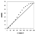
図6は、入力画像信号に対する画像濃度の関係を示すグラフである。横軸は、入力画像信号(入力データ)を示している。また、縦軸は、画像濃度を示している。図中のドットが、実際に濃度検出センサ17により得られた検出濃度を示している。また、図中の直線は、基準濃度を示している。このようにして得られた中間調(ハーフトーン)の濃度を元に、入力画像信号と画像濃度との関係がリニアとなるように、画像形成装置が画像処理を行う。このようなDhalf制御は、装置本体の電源がONにされた時、カートリッジが交換された時、印刷枚数が所定枚数(例:100枚)に達した時などに実行される。
FIG. 6 is a graph showing the relationship between the image density and the input image signal. The horizontal axis represents the input image signal (input data). The vertical axis indicates the image density. The dots in the figure indicate the detected density actually obtained by the
[トナー補給制御について]
本実施形態に係るトナー補給制御によれば、ビデオカウントにより算出された補給量t1のトナーがすぐに補給されることはない。すなわち、補給量t1は、一旦、積算値t2として蓄えられる。さらに、トナーホッパー5が一回の動作で補給する量t3が、トナーの劣化の程度(すなわち、濃度制御において検出された画像濃度)に応じて決定されることに特徴がある。
[Toner supply control]
According to the toner replenishment control according to the present embodiment, the toner of the replenishment amount t1 calculated by the video count is not replenished immediately. That is, the replenishment amount t1 is temporarily stored as the integrated value t2. Further, the amount t3 of replenishment by the
図7は、実施形態に係る入力画像信号に対する画像濃度の関係を示すグラフである。とりわけ、図中の黒ドットは、カートリッジ寿命の初期における入出力特性を示している。一方、白抜きドットは、カートリッジ寿命の終期における入出力特性を示している。 FIG. 7 is a graph showing the relationship between the image density and the input image signal according to the embodiment. In particular, black dots in the figure indicate input / output characteristics at the beginning of the cartridge life. On the other hand, white dots indicate input / output characteristics at the end of the cartridge life.
図から、寿命終期の入出力特性は、初期の入出力特性よりも理想的な特性から大きくずれていることがわかる。特に、低濃度付近や高濃度付近よりも中間濃度付近で大きなずれを確認できる。ずれの主要因はトナーの劣化である。よって、CPU35は、この入出力特性の結果からトナーの劣化程度を推測できる。
From the figure, it can be seen that the input / output characteristics at the end of the life are greatly deviated from the ideal characteristics than the initial input / output characteristics. In particular, a large shift can be confirmed near the intermediate density than near the low density or high density. The main factor of deviation is toner deterioration. Therefore, the
図7によれば、中間調の階調レベルが、表現可能な最大階調(図7では256階調)の8分の1(階調レベル:32)ないし4分の3(階調レベル:192)となるときに、初期時と終期時における入出力特性に差が現れやすいことがわかる。とりわけ、中間調のレベルが、表現可能な最大階調の4分の1(階調レベル:64)ないし2分の1(階調レベル:128)となるときに、初期時と終期時における入出力特性の差が顕著となる。よって、本実施形態において、CPU35は、階調レベルが96となる中間調画像を所定のタイミングで感光ドラム1上に形成させ、検出された濃度を基準濃度と比較することで、閾値調整の可否を決定したり、閾値を調整したりする。例えば、CPU35は、検出された濃度と、記憶装置40に記憶されている基準濃度との差に応じて、閾値を補正するための補正係数Xを決定し、決定された閾値Xにより閾値を調整する。
According to FIG. 7, the gradation level of the halftone is one eighth (gradation level: 32) to three quarters (gradation level: 32) of the maximum gradation (256 gradations in FIG. 7) that can be expressed. 192), it can be seen that a difference tends to appear in the input / output characteristics at the initial time and at the final time. In particular, when the halftone level is between one-fourth (gradation level: 64) to half (gradation level: 128) of the maximum gradation that can be expressed, The difference in output characteristics becomes significant. Therefore, in this embodiment, the
以下では、本実施形態に係るトナー補給方法についてフローチャートを用いてさらに詳しく説明する。まず、本実施形態で用いたパラメータの一覧を以下に示す。 Hereinafter, the toner supply method according to the present embodiment will be described in more detail with reference to flowcharts. First, a list of parameters used in this embodiment is shown below.
A :潜像担持体上に担持された単位面積あたりのトナー載り量(例:0.6mg/cm2)
S :記録剤の面積(例:A4紙サイズで21.0×29.7cm2)
R :ビデオカウントより算出される画像印字比率(0〜1.0)
t1 :記録剤1枚当りのトナー消費量(t1=A×S×R)
t1max :印字比率Rが最大となるときのトナー消費量(例:374mg)
t2 :トナー消費量の積算値
X :補正係数
t3 :1回あたりの補給量(閾値)
t4 :補正後の閾値(t4=t3 ・ X)
Y :基準濃度(理想的な濃度値)
Δ :理想的濃度と検出濃度との差分
ここで、トナーの載り量Aや記録剤の面積Sは、使用される記録剤のサイズは、トナーパッチを検出することによる濃度調整によって随時修正されるが、本実施形態では影響因子を少なくするために固定値としている。
図8は、実施形態に係るトナー補給制御の一例を示すフローチャートである。トナー補給制御は、画像形成装置の本体の電源ONにされると開始される。上述したように、濃度制御(Dhalf制御)は、装置本体の電源ON時のほかにも、カートリッジの交換時、所定の印刷枚数ごとに実行されてもよい。ここでは、説明の簡略化のために、電源ON時にのみ濃度制御が実行されるものとして説明するが、他の濃度制御のタイミングにおいても、画像濃度の検出処理および閾値の調整処理が実行されてもよい。
A: Amount of applied toner per unit area carried on the latent image carrier (example: 0.6 mg / cm 2 )
S: Area of recording agent (example: 21.0 × 29.7 cm 2 for A4 paper size)
R: Image printing ratio calculated from video count (0 to 1.0)
t1: Toner consumption per recording material (t1 = A × S × R)
t1max: Amount of toner consumed when the print ratio R is maximized (example: 374 mg)
t2: Toner consumption integrated value X: Correction coefficient t3: Replenishment amount per time (threshold)
t4: threshold value after correction (t4 = t3 · X)
Y: Reference density (ideal density value)
Δ: Difference between ideal density and detected density Here, the applied amount A of toner and the area S of the recording material are corrected at any time by adjusting the density by detecting the toner patch. However, in this embodiment, a fixed value is used in order to reduce the influence factor.
FIG. 8 is a flowchart illustrating an example of toner supply control according to the embodiment. The toner supply control is started when the main body of the image forming apparatus is turned on. As described above, the density control (Dhalf control) may be executed for every predetermined number of printed sheets when the cartridge is replaced in addition to when the apparatus main body is turned on. Here, for simplification of description, it is assumed that the density control is executed only when the power is turned on, but the image density detection process and the threshold adjustment process are also executed at other density control timings. Also good.
ステップS801において、CPU35は、濃度制御(例:Dhalf制御)を実行する。上述したように、CPU35は、感光ドラム1上に中間調のトナー像を形成し、形成されたトナー像の濃度を濃度検出センサ17により検出する。CPU35は、検出された濃度に基づいて、濃度制御を実行する。
In step S801, the
ステップS802において、CPU35は、Dhalf制御において得られた入出力特性から所定の中間調(例:階調レベル:96)に対応する濃度情報を取得する。ステップ803において、CPU35は、記憶装置40に予め記憶されている基準濃度Yを読み出し、基準濃度と検出された濃度とを比較する。すなわち、CPU35は、両濃度の差分Δを算出する。
In step S802, the
ステップS804において、CPU35は、差分Δに基づいて閾値t4を決定する。例えば、CPU35は、差分Δに応じて補正係数Xを決定する。差分Δと、対応する補正係数Xとの関係は、予めテーブル化されていてもよい。このテーブルは、例えば、記憶装置40に記憶されていてもよい。さらに、CPU35は、初期の閾値t3に補正係数Xを乗算することでt4を算出する。算出された閾値t4は、1回の補給動作における補給量としても利用される。
In step S804, the
ステップ805において、CPU35は、プリント動作の開始が指示されるまで待機する。プリント動作の開始が指示されると、ステップS806に進み、CPU35は、感光ドラム1、帯電装置2、露光装置3などを順次起動させる。CPU35は、各装置の準備が整うと、露光装置3を作動させて、感光ドラム1上に潜像を形成する。また、CPU35は、カウンタ34にビデオカウントを開始させる。潜像形成が終わると、ステップS807に進み、CPU35は、露光装置2を停止させる。また、CPU35は、ビデオカウントを終了させる。ステップS808において、CPU35は、カウンタ34からビデオカウント値を取得する。ステップS809において、CPU35は、ビデオカウント値を元にトナーの消費量(推定値)t1を算出する。ステップS810において、CPU35は、消費量t1を積算することで積算値t2を算出する(t2=t2+t1)。
In step 805, the
ステップS811において、CPU35は、積算値t2と閾値t4を比較する。すなわち、CPU35は、積算値t2が閾値t4を超えているか否かを判定する。超えていなければ、ステップS812に進む。一方、超えていれば、ステップS820に進み、CPU35は、トナーホッパー5を駆動させ、t4に相当する量のトナーを補給する。ステップS821に進み、CPU35は、積算値t2から補給量t4を減算する。すなわち、積算値t2と補給量t4との差が、次のビデオカウントの初期値となる。
In step S811, the
その後、ステップS812に進み、CPU35は、ジョブが終了するか否かを判定する。ジョブが終了しない場合は、次の記録媒体Pに画像を形成すべく、ステップS806に戻る。ジョブが終了であれば、CPU35は、プリント動作の終了処理を実行する。
Thereafter, the process proceeds to step S812, and the
図9は、実施形態に係る補給モーターの回転数と補給量との関係を示す図である。本実施形態によれば、CPU35がトナーホッパー5の補給モーターの回転数を制御することで、t4に相当するトナーが補給される。図9によれば、補給モーターが2回転すると、400mgのトナーを補給できることが示されている。また、補給モーターが1回転すると、200mgのトナーを補給できる。CPU35は、補給量t4に相当する回転数を図9に示す関係(この関係は、テーブル等に保持されている。)から取得して、回転数をトナーホッパー5の補給モーターに設定する。この場合、補給量を調整することは、補給モータの回転数を調整することに相当するといえよう。
FIG. 9 is a diagram illustrating a relationship between the number of rotations of the supply motor and the supply amount according to the embodiment. According to this embodiment, the
本実施形態によれば、現像剤の劣化の程度に応じて、1回で補給される現像剤の量を調整することことができる。これにより、現像装置4の帯電能力を超えるほどの大量のトナーが一度に補給されることを抑制することができる。すなわち、かぶり、濃度ムラまたはトナー飛散などの好ましくない現象を抑制することが可能となる。 According to the present embodiment, the amount of developer that is replenished at one time can be adjusted according to the degree of deterioration of the developer. Thereby, it is possible to prevent a large amount of toner exceeding the charging capability of the developing device 4 from being supplied at a time. That is, undesirable phenomena such as fogging, density unevenness, and toner scattering can be suppressed.
また、ベタ画像を形成するときの現像剤の消費量である最大消費量t1maxよりも小さく閾値t4を設定することで、高印字時の補給量を少なくすることができる。これにより、補給トナーが一度に大量に補給されることに起因する攪拌不足や帯電不足を抑制できる。すなわち、かぶりなどを防止することが可能となる。 Further, the replenishment amount at the time of high printing can be reduced by setting the threshold value t4 smaller than the maximum consumption amount t1max that is the consumption amount of the developer when forming a solid image. Thereby, insufficient stirring and insufficient charging due to a large amount of supply toner being supplied at a time can be suppressed. That is, it is possible to prevent fogging and the like.
しかし、閾値t4をあまりにも小さくしてしまうと、高印字時にトナーが不足してしまい、最悪の場合、現像容器内が空になってしまう。そこで、例えば、現像容器内の残量の狙い値を150gとした場合、残量検知センサ15は、残量が130gであることを検出すると、トナーレベルLow警告を出力する。また、残量検知センサ15は、残量が170gであることを検出すると、トナーレベルHi警告を出力する。とりわけ、CPU35は、Low警告を受信すると、残量の復帰シーケンスを実行してもよい。復帰シーケンスとしては、例えば、現像容器内に5gのトナー量が補給されるまで、一定時間にわたり、補給モーターを回転させるシーケンスがある。これにより、現像容器16内のトナー量を一定に保つことが可能となろう。
However, if the threshold value t4 is too small, the toner is insufficient during high printing, and in the worst case, the inside of the developing container is emptied. Therefore, for example, when the target value of the remaining amount in the developing container is 150 g, the remaining
ところで、かぶりを起こさずに補給できるトナー量の最大値は、使用状況や環境などにより異なる。なぜならば、トナー劣化が進むにしたがって、トナーの帯電性が低下するからである。また、現像装置2を構成している各パーツが劣化してゆくことで、トナーに対する帯電付与能力も減衰してゆくことも原因の1つである。そこで、かぶりの抑制と高印字時の補給不足とを両立させるためには、かぶりを起こさない範囲で初期閾値t3を可能な限り大きな値とすることが必要である。また、トナー濃度は、トナーの劣化を表す尺度の好例である。よって、濃度制御時に検出されたトナー像の濃度情報から、CPU35が、トナーの劣化状態を推測し、推測結果に応じて補給量t3をt4へと調整することが望ましいといえる。
By the way, the maximum amount of toner that can be replenished without causing fogging varies depending on the use situation and environment. This is because as the toner deteriorates, the chargeability of the toner decreases. Another reason is that as the parts constituting the developing
なお、濃度制御時に形成されるトナー像は、中間調であることが好ましい。図6や図7を用いて説明したように、中間調のトナー像において、トナーの劣化に応じた濃度の変化が現れやすいからである。好ましくは、中間調の階調レベルは、表現可能な最大階調の8分の1ないし4分の3である。さらに好ましくは、中間調の階調レベルは、表現可能な最大階調の4分の1ないし2分の1である。 The toner image formed during density control is preferably halftone. This is because, as described with reference to FIGS. 6 and 7, in a halftone toner image, a change in density according to toner deterioration tends to appear. Preferably, the halftone gradation level is 1/8 to 3/4 of the maximum representable gradation. More preferably, the gradation level of the halftone is one quarter to one half of the maximum representable gradation.
図10は、実施形態に係る濃度差分Δと補正係数Xとの対応関係の一例を示す図である。濃度差分Δと補正係数Xとの対応関係は、例えば、テーブルを作成して管理してもよい。図10に示されるテーブルによれば、トナー劣化の程度を10段階に区分けし、各段階に対応する補正係数Xが登録されている。CPU35は、記憶装置40に記憶されているテーブルを用いて、濃度差分Δに対応する補正係数Xを容易に決定できる。
FIG. 10 is a diagram illustrating an example of a correspondence relationship between the density difference Δ and the correction coefficient X according to the embodiment. The correspondence between the density difference Δ and the correction coefficient X may be managed by creating a table, for example. According to the table shown in FIG. 10, the degree of toner deterioration is divided into 10 levels, and the correction coefficient X corresponding to each level is registered. The
なお、本実施形態に係る現像装置4(寿命:4万枚)について耐久試験を行ったところ、使用初期から終期にわたり、濃度ムラやかぶりは発生しなかった。また、トナーの供給量不足や供給過多といった現象も発生することがなかった。 In addition, when a durability test was performed on the developing device 4 (life: 40,000 sheets) according to this embodiment, density unevenness and fog did not occur from the initial use to the end. In addition, there was no occurrence of a phenomenon such as insufficient supply amount or excessive supply of toner.
また、本実施形態では、階調レベルが96であるときのトナー像の濃度を用いて、補給量(閾値)を調整したが、本発明はこれに限定されることはない。現像装置4の使用の初期と終期とで、入出力特性に顕著な差が生じうる他の1以上の階調レベルを用いてもよい。さらに、濃度検出の対象となる階調レベルは一つである必要はなく、2以上であってもよい。複数の階調レベルについて濃度を検出する場合、CPU35は、検出された複数の濃度の合計値や平均値を理想値と比較してもよい。また、CPU35は、複数の検出濃度から傾きを算出し、理想の傾きと比較してもよい。
In this embodiment, the replenishment amount (threshold) is adjusted using the density of the toner image when the gradation level is 96, but the present invention is not limited to this. One or more other gradation levels that may cause a significant difference in input / output characteristics between the initial stage and the final stage of use of the developing device 4 may be used. Furthermore, the gradation level to be subjected to density detection need not be one, and may be two or more. When detecting densities for a plurality of gradation levels, the
[他の実施形態]
上述の実施形態では、説明の便宜上、モノクロ方式の画像形成装置について説明したが、本発明は、複数のプロセスカートリッジを搭載したカラー画像形成装置にも適用できる。また、各色のプロセスカートリッジに不揮発性メモリ(記憶装置40)を搭載し、理想的な初期濃度を記憶させるようにしてもよい。
[Other Embodiments]
In the above-described embodiment, the monochrome image forming apparatus has been described for convenience of explanation, but the present invention can also be applied to a color image forming apparatus in which a plurality of process cartridges are mounted. In addition, a non-volatile memory (storage device 40) may be mounted on each color process cartridge to store an ideal initial density.
図11、実施形態に係るカラー画像形成装置の概略断面図である。カラー画像形成装置は、例えば、複写機、プリンタ、ファクシミリ、複合機などとして市場に提供されることが多い。 FIG. 11 is a schematic sectional view of the color image forming apparatus according to the embodiment. A color image forming apparatus is often provided on the market as, for example, a copying machine, a printer, a facsimile machine, or a multifunction machine.
このカラー画像形成装置は、4つのプロセスカートリッジ4Y、4M、4C、4Kを備えている。また、各プロセスカートリッジは、所定の使用量に到来すると画像形成装置から外されて、新しいプロセスカートリッジと交換される。なお、各プロセスカートリッジは、上述した感光ドラム1や帯電装置2などを備えている。プロセスカートリッジの詳細は、上述したとおりである。各プロセスカートリッジに対して、トナーホッパー5Y、5M、5C、5Kが設けられている。このトナーホッパーも画像形成装置から取り外して交換することが可能となっている。
This color image forming apparatus includes four
各感光ドラム1の表面に形成された各色のトナー像は、プロセスカートリッジの配置された順にしたがって中間転写体61上に多重形成される。各プロセスカートリッジについての濃度制御も上述した通りに実行される。また、トナーの補給制御も各プロセスカートリッジごとに独立して実行される。
The toner images of the respective colors formed on the surface of each
このようなフルカラー画像形成装置においては、多色の画像が一枚の記録媒体上に重ねられる。そのため、かぶりに関しては、フルカラー画像形成装置はモノクロ画像形成装置よりもはるかに高い品質が要求される。よって、本発明に係るトナー補給方法は、フルカラー画像形成装置に採用されることが望ましい。 In such a full-color image forming apparatus, multicolor images are superimposed on a single recording medium. Therefore, with respect to fog, a full-color image forming apparatus is required to have a much higher quality than a monochrome image forming apparatus. Therefore, it is desirable that the toner replenishing method according to the present invention is employed in a full-color image forming apparatus.
1:感光ドラム
2:帯電装置
3:露光装置
4:現像装置
5:補給装置(トナーホッパー)
1: Photosensitive drum 2: Charging device 3: Exposure device 4: Developing device 5: Replenishing device (toner hopper)
Claims (11)
形成される画像についての印字比率に基づいて、該画像を形成する際に消費される現像剤の消費量を推定する推定手段と、
画像ごとに推定された前記消費量を積算する積算手段と、
積算された前記消費量が閾値を超えたか否かを判定する判定手段と、
積算された前記消費量が前記閾値を超えると、前記閾値に相当する一定量の現像剤を現像容器へ補給する補給手段と、
前記現像容器に収納されている現像剤の劣化の程度を推測する推測手段と、
前記現像剤の劣化の程度に応じて前記閾値を調整する調整手段と
を含むことを特徴とする画像形成装置。 An image forming apparatus that forms an image using a developer,
An estimation means for estimating a consumption amount of a developer consumed when forming the image based on a printing ratio for the image to be formed;
Integration means for integrating the consumption estimated for each image;
Determination means for determining whether or not the accumulated consumption exceeds a threshold;
Replenishing means for replenishing a developer container with a constant amount of developer corresponding to the threshold when the accumulated consumption exceeds the threshold;
An estimation means for estimating the degree of deterioration of the developer stored in the developer container;
An image forming apparatus comprising: an adjusting unit that adjusts the threshold according to a degree of deterioration of the developer.
記録媒体または像担持体上に形成された基準となる現像剤像の濃度を検出する検出手段を含み、
前記調整手段は、検出された前記現像剤像の濃度に応じて前記閾値を調整することを特徴とする請求項1または2に記載の画像形成装置。 The inference means is
A detection means for detecting the density of a developer image serving as a reference formed on the recording medium or the image carrier,
The image forming apparatus according to claim 1, wherein the adjusting unit adjusts the threshold value according to the detected density of the developer image.
前記中間調に対応する現像剤の基準濃度を記憶する記憶手段と、
前記中間調の現像剤像から検出された濃度と、前記理想濃度とを比較する比較手段と、
検出された前記濃度と前記基準濃度との差に応じて前記閾値を補正するための補正係数を決定する決定手段と
を含み、
決定された前記補正係数を用いて前記閾値を調整することを特徴とする請求項4ないし6の何れかに記載の画像形成装置。 The adjusting means includes
Storage means for storing a reference density of the developer corresponding to the halftone;
A comparison means for comparing the density detected from the halftone developer image with the ideal density;
Determining means for determining a correction coefficient for correcting the threshold according to a difference between the detected density and the reference density;
The image forming apparatus according to claim 4, wherein the threshold value is adjusted using the determined correction coefficient.
潜像の印字比率に基づいて、該潜像を現像する際に消費される現像剤の消費量を推定する推定手段と、
潜像ごとの前記消費量を積算する積算手段と、
積算された前記消費量が閾値を超えたか否かを補給時期ごとに判定する判定手段と、
積算された前記消費量が前記閾値を超えると、前記閾値に相当する一定量の現像剤を現像容器へ補給する補給手段と、
前記現像容器に収納されている現像剤の劣化の程度を推測する推測手段と、
前記現像剤の劣化の程度に応じて前記閾値を調整する調整手段と
を含むことを特徴とする現像装置。 A developing device for developing a latent image on a photoreceptor using a developer,
Estimating means for estimating a consumption amount of a developer consumed when developing the latent image based on a printing ratio of the latent image;
Integrating means for integrating the consumption for each latent image;
Determining means for determining, for each replenishment period, whether or not the accumulated consumption exceeds a threshold;
Replenishing means for replenishing a developer container with a constant amount of developer corresponding to the threshold when the accumulated consumption exceeds the threshold;
An estimation means for estimating the degree of deterioration of the developer stored in the developer container;
And an adjusting unit that adjusts the threshold according to the degree of deterioration of the developer.
潜像を担持する像担持体と、
前記潜像を現像する、請求項8に記載の現像装置と
を一体に構成したことを特徴とするプロセスカートリッジ。 A process cartridge,
An image carrier for carrying a latent image;
9. A process cartridge comprising the developing device according to claim 8, wherein the latent image is developed.
形成される画像についての印字比率に基づいて、該画像を形成する際に消費される現像剤の消費量を推定する推定工程と、
画像ごとに推定された前記消費量を積算する積算工程と、
積算された前記消費量が閾値を超えたか否かを補給時期ごとに判定する判定工程と、
積算された前記消費量が前記閾値を超えると、前記閾値に相当する一定量の現像剤を現像容器へ補給する補給工程と、
前記現像容器に収納されている現像剤の劣化の程度を推測する推測工程と、
前記現像剤の劣化の程度に応じて前記閾値を調整する調整工程と
を含むことを特徴とする現像剤の補給方法。 A developer replenishment method comprising:
An estimation step of estimating a consumption amount of developer consumed when forming the image based on a printing ratio of the image to be formed;
An integration step of integrating the estimated consumption for each image;
A determination step of determining, for each replenishment period, whether or not the accumulated consumption exceeds a threshold;
A replenishment step of replenishing a developer container with a certain amount of developer corresponding to the threshold when the accumulated consumption exceeds the threshold;
An estimation step of estimating the degree of deterioration of the developer stored in the developer container;
An adjusting step of adjusting the threshold according to the degree of deterioration of the developer.
Priority Applications (1)
| Application Number | Priority Date | Filing Date | Title |
|---|---|---|---|
| JP2006159138A JP2007328126A (en) | 2006-06-07 | 2006-06-07 | An image forming apparatus, a developing apparatus, and a developer replenishing method. |
Applications Claiming Priority (1)
| Application Number | Priority Date | Filing Date | Title |
|---|---|---|---|
| JP2006159138A JP2007328126A (en) | 2006-06-07 | 2006-06-07 | An image forming apparatus, a developing apparatus, and a developer replenishing method. |
Publications (1)
| Publication Number | Publication Date |
|---|---|
| JP2007328126A true JP2007328126A (en) | 2007-12-20 |
Family
ID=38928646
Family Applications (1)
| Application Number | Title | Priority Date | Filing Date |
|---|---|---|---|
| JP2006159138A Withdrawn JP2007328126A (en) | 2006-06-07 | 2006-06-07 | An image forming apparatus, a developing apparatus, and a developer replenishing method. |
Country Status (1)
| Country | Link |
|---|---|
| JP (1) | JP2007328126A (en) |
Cited By (3)
| Publication number | Priority date | Publication date | Assignee | Title |
|---|---|---|---|---|
| JP2009265582A (en) * | 2008-04-30 | 2009-11-12 | Ricoh Co Ltd | Image forming apparatus and image forming method |
| CN108717252A (en) * | 2017-03-31 | 2018-10-30 | 兄弟工业株式会社 | The method of image forming apparatus and control image forming apparatus |
| CN111273528A (en) * | 2018-12-05 | 2020-06-12 | 柯尼卡美能达株式会社 | Image forming apparatus, degradation state detection method, and storage medium |
-
2006
- 2006-06-07 JP JP2006159138A patent/JP2007328126A/en not_active Withdrawn
Cited By (5)
| Publication number | Priority date | Publication date | Assignee | Title |
|---|---|---|---|---|
| JP2009265582A (en) * | 2008-04-30 | 2009-11-12 | Ricoh Co Ltd | Image forming apparatus and image forming method |
| CN108717252A (en) * | 2017-03-31 | 2018-10-30 | 兄弟工业株式会社 | The method of image forming apparatus and control image forming apparatus |
| US11226572B2 (en) | 2017-03-31 | 2022-01-18 | Brother Kogyo Kabushiki Kaisha | Process unit, developing cartridge and toner cartridge for use with image forming apparatus |
| CN108717252B (en) * | 2017-03-31 | 2022-06-14 | 兄弟工业株式会社 | Image forming apparatus and method of controlling image forming apparatus |
| CN111273528A (en) * | 2018-12-05 | 2020-06-12 | 柯尼卡美能达株式会社 | Image forming apparatus, degradation state detection method, and storage medium |
Similar Documents
| Publication | Publication Date | Title |
|---|---|---|
| US7684715B2 (en) | Image forming apparatus capable of stably maintaining an image density | |
| US9164459B2 (en) | Image forming apparatus | |
| US20070081829A1 (en) | Image forming apparatus and output image density correction method | |
| US7149437B2 (en) | Image forming apparatus, and control system, cartridge and memory medium for the same apparatus | |
| JP6025407B2 (en) | Image forming apparatus | |
| JP2010128082A (en) | Developing device and image forming apparatus | |
| JP2010145481A (en) | Development device and image forming apparatus | |
| US9523954B2 (en) | Image forming apparatus that performs developer replenishment | |
| JP2011227367A (en) | Developing device, image-forming apparatus, and toner replenishing method | |
| JP4935800B2 (en) | Developing device and image forming apparatus | |
| JP2010156882A (en) | Image forming apparatus | |
| JP4641404B2 (en) | Image forming apparatus | |
| JP2010002537A (en) | Image forming apparatus, control method of image forming apparatus, and control program for the image forming apparatus | |
| JP2007328126A (en) | An image forming apparatus, a developing apparatus, and a developer replenishing method. | |
| JP2013161022A (en) | Image forming apparatus | |
| JP4887949B2 (en) | Image forming apparatus and toner density control method | |
| JP2004085710A (en) | Image forming device | |
| JP2019148771A (en) | Image forming device | |
| JP2007292803A (en) | Image forming apparatus, process cartridge, and control method | |
| JP2010113289A (en) | Developing device and image forming apparatus | |
| JP2008268679A (en) | Image forming apparatus | |
| JP2008020695A (en) | Image forming apparatus | |
| JP4040317B2 (en) | Developing device and image forming apparatus having the same | |
| JP5028902B2 (en) | Development device | |
| JP2013122549A (en) | Image density control method and image forming apparatus |
Legal Events
| Date | Code | Title | Description |
|---|---|---|---|
| A300 | Withdrawal of application because of no request for examination |
Free format text: JAPANESE INTERMEDIATE CODE: A300 Effective date: 20090901 |