JP2007328030A - Imaging apparatus, optical device and lens - Google Patents
Imaging apparatus, optical device and lens Download PDFInfo
- Publication number
- JP2007328030A JP2007328030A JP2006157471A JP2006157471A JP2007328030A JP 2007328030 A JP2007328030 A JP 2007328030A JP 2006157471 A JP2006157471 A JP 2006157471A JP 2006157471 A JP2006157471 A JP 2006157471A JP 2007328030 A JP2007328030 A JP 2007328030A
- Authority
- JP
- Japan
- Prior art keywords
- lens
- anamorphic
- optical system
- imaging
- image
- Prior art date
- Legal status (The legal status is an assumption and is not a legal conclusion. Google has not performed a legal analysis and makes no representation as to the accuracy of the status listed.)
- Pending
Links
Images


Landscapes
- Lenses (AREA)
- Studio Devices (AREA)
Abstract
Description
本発明は、アナモルフィック光学系により、縦方向及び横方向に異なる倍率で結像される像を撮像する撮像装置、この撮像装置に搭載される光学装置及びレンズに関する。 The present invention relates to an imaging device that captures images formed at different magnifications in the vertical and horizontal directions by an anamorphic optical system, and an optical device and a lens mounted on the imaging device.
近年、車両に撮像装置を搭載し、撮像装置が撮像した画像を基に運転者へ種々の情報を提供するシステムが実用化されている。例えば、車両の運転席から死角となる部分を撮像する撮像装置を搭載することによって、運転者が直接に目視できない部分を車内のディスプレイに表示することができる。車両に搭載される撮像装置は、1つの撮像装置で広い範囲を撮像することが要求され、特に路面に対する水平方向について広い範囲を撮像することが求められる。しかし、路面に対する垂直方向については、水平方向と比較して、それほど広い範囲を撮像することが求められるわけではなく、路面から水平線までの撮像範囲程度で十分である。 In recent years, a system in which an imaging device is mounted on a vehicle and various information is provided to a driver based on an image captured by the imaging device has been put into practical use. For example, by mounting an image pickup device that picks up a blind spot from the driver's seat of the vehicle, a portion that cannot be directly seen by the driver can be displayed on a display inside the vehicle. An image pickup apparatus mounted on a vehicle is required to pick up a wide range with one image pickup apparatus, and in particular, it is required to pick up a wide range in the horizontal direction with respect to the road surface. However, in the vertical direction with respect to the road surface, it is not required to image a very wide range compared to the horizontal direction, and an imaging range from the road surface to the horizontal line is sufficient.
このように、特定の方向のみに広い撮像範囲が求められる撮像装置では、例えばシリンドリカルレンズなどの縦方向及び横方向で曲率の異なる曲面を有するレンズを用いたアナモルフィック光学系を利用することにより、特定の方向に広い範囲で撮像を行うようにしてある。図5は、アナモルフィック光学系を備える従来の撮像装置の構成を示す模式的断面図であり、(a)には撮像装置の垂直方向(縦方向)での断面を示し、(b)には水平方向(横方向)での断面を示してある。図において200は、10個のレンズ201〜210、絞り120及びフィルタ125により構成されたアナモルフィック光学系であり、アナモルフィック光学系200により結像された像を撮像素子130にて撮像するようにしてある。
Thus, in an imaging apparatus that requires a wide imaging range only in a specific direction, for example, by using an anamorphic optical system using a lens having curved surfaces with different curvatures in the vertical and horizontal directions such as a cylindrical lens. The imaging is performed over a wide range in a specific direction. FIG. 5 is a schematic cross-sectional view showing a configuration of a conventional image pickup apparatus including an anamorphic optical system. FIG. 5A shows a cross section in the vertical direction (longitudinal direction) of the image pickup apparatus, and FIG. Shows a cross section in the horizontal direction (lateral direction). In the figure,
アナモルフィック光学系200のレンズ201、202、205、207、208、209、210は、縦方向及び横方向の曲率が等しい曲面を有するレンズであり、光軸方向での平面視で円形をなしている。レンズ203、204、206は、縦方向及び横方向の曲率が異なる曲面を有するアナモルフィックレンズであり、この3つのレンズを備えることによって、アナモルフィック光学系200は、縦方向及び横方向で異なる倍率で撮像素子130へ像を結像することができる。図中には撮像素子130への光線の光路が破線にて図示してあるが、アナモルフィック光学系200を備えるこの撮像装置では、縦方向の撮像範囲(図5(a)参照)より、横方向の撮像範囲(図5(b)参照)が広くなっている。
The
同様の構成として、例えば特許文献1においては、撮像の対象側から順に負レンズ、負レンズ及び正レンズからなる前群と、負レンズ及び正レンズの接合レンズ、並びに正レンズからなる後群とを有する超広角光学系を備え、特定方向に広い画角を有する撮像装置が提案されている。この撮像装置では、前群の2つ目のレンズの両面をアナモルフィック面とし、後群の3つ目のレンズは一面をアナモルフィック面とし、他面を非球面とすることによって、アナモルフィック光学系を構成し、特定方向に広い範囲で撮像を行うことができるようにしてある。
これらの撮像装置においては、より広い撮像範囲を得るために、より多くのレンズが搭載されると共に、レンズが大型化し、撮像装置が大型化するという問題がある。特に、光の入射側の一端に配されるレンズ201は、より多くの光を入射させる必要があるため、大型のレンズが用いられ、撮像装置の小型化がレンズ201により阻害されている。例えば、撮像装置を車両に搭載して車両周辺の撮像を行う場合、レンズ201及びその周辺部分は車外へ向けて露出する部分であり、車外から視認される可能性が高いため、車両の意匠性を損なう虞があり、レンズ201及びその周辺部分はより小型であることが望まれる。また、撮像装置をその他の機器に搭載する場合であっても、搭載スペースの関係から、撮像装置はより小型であることが望まれる。
In these imaging apparatuses, in order to obtain a wider imaging range, there are problems that a larger number of lenses are mounted, the lenses are enlarged, and the imaging apparatus is enlarged. In particular, since the
本発明は、斯かる事情に鑑みてなされたものであって、その目的とするところは、アナモルフィック光学系により結像された像を撮像素子により撮像する場合に、光軸に直交し且つ互いに直交する二方向の曲率が等しい等曲面レンズの形状を、撮像素子に結像する光線が通過しない領域を切り欠いた非円形とすることにより、レンズの小型化に伴って小型化できる撮像装置を提供することにある。 The present invention has been made in view of such circumstances, and an object of the present invention is to orthogonally intersect the optical axis when an image formed by an anamorphic optical system is picked up by an image pickup device, and An imaging device that can be miniaturized as the lens is miniaturized by making the shape of an isosurface lens with equal curvatures in two directions orthogonal to each other into a non-circular shape by cutting out a region through which light rays focused on the imaging element do not pass. Is to provide.
また本発明の他の目的とするところは、複数の等曲面レンズ及びアナモルフィックレンズが同軸的に配されてアナモルフィック光学系が構成されている場合に、最も入射側に配された等曲面レンズを非円形とすることにより、より効果的に小型化できる撮像装置を提供することにある。 Another object of the present invention is that when an anamorphic optical system is configured by coaxially arranging a plurality of isosurface lenses and an anamorphic lens, the lens is arranged on the most incident side, etc. An object of the present invention is to provide an imaging device that can be more effectively downsized by making a curved lens non-circular.
また本発明の他の目的とするところは、非円形の等曲面レンズをガラスにより形成することにより、耐久性に優れ、且つ、より広範囲な撮像を行うことができる撮像装置を提供することにある。 Another object of the present invention is to provide an imaging apparatus that is excellent in durability and capable of imaging a wider range by forming a non-circular isometric lens from glass. .
また本発明の他の目的とするところは、非円形の等曲面レンズを合成樹脂により形成することにより、容易に等曲面レンズを形成することができる撮像装置を提供することにある。 Another object of the present invention is to provide an imaging device that can easily form an iso-curved lens by forming a non-circular iso-curved lens from a synthetic resin.
また本発明の他の目的とするところは、一面に凸面が形成され、他面に凹面が形成されたメニスカスレンズを非円形とすることにより、広範囲を撮像する場合に用いられるメニスカスレンズを小型化できる撮像装置を提供することにある。 Another object of the present invention is to reduce the size of a meniscus lens used for imaging a wide area by forming a non-circular meniscus lens having a convex surface on one surface and a concave surface on the other surface. An object of the present invention is to provide an imaging device capable of performing the above.
また本発明の他の目的とするところは、光軸に直交し且つ互いに直交する二方向で曲率が異なるアナモルフィック面を有するアナモルフィックレンズと、曲率が等しい曲面を有する等曲面レンズとを備えて被結像体への結像を行う場合に、等曲面レンズの形状を、被結像体に結像する光線が通過しない領域を切り欠いた非円形とすることにより、レンズの小型化に伴って小型化できる光学装置を提供することにある。 Another object of the present invention is to provide an anamorphic lens having an anamorphic surface having different curvatures in two directions orthogonal to the optical axis and orthogonal to each other, and an isosurface lens having a curved surface having the same curvature. In order to form an image on the imaged object, the lens surface can be made smaller by making the shape of the iso-curved lens a non-circular shape by cutting out the area through which the light beam that forms the imaged object does not pass. Accordingly, an object of the present invention is to provide an optical device that can be downsized.
また本発明の他の目的とするところは、光軸に直交し且つ互いに直交する二方向で曲率が等しい曲面を有し、被結像体への結像を行う場合に、被結像体に結像する光線が通過しない領域を切り欠いた非円形の形状とすることにより、小型化することができるレンズを提供することにある。 Another object of the present invention is to have a curved surface having the same curvature in two directions perpendicular to the optical axis and perpendicular to each other, and when imaging on the imaging target, It is an object of the present invention to provide a lens that can be reduced in size by forming a non-circular shape in which a region through which an imaged ray does not pass is cut out.
第1発明に係る撮像装置は、光軸に直交し且つ互いに直交する二方向で曲率が異なるアナモルフィック面を有するアナモルフィックレンズ、及び前記二方向で曲率が等しい曲面を有する等曲面レンズを有し、前記二方向で倍率が異なるアナモルフィック光学系と、該アナモルフィック光学系により結像された像を撮像する撮像素子とを備える撮像装置において、前記等曲面レンズの形状が、前記撮像素子に結像する光線が通過しない領域を切り欠いた非円形であることを特徴とする。 An imaging apparatus according to a first aspect of the present invention includes an anamorphic lens having an anamorphic surface having different curvatures in two directions orthogonal to the optical axis and orthogonal to each other, and an isosurface lens having a curved surface having the same curvature in the two directions. An imaging device comprising: an anamorphic optical system having different magnifications in the two directions; and an imaging device that captures an image formed by the anamorphic optical system. A non-circular shape in which a region through which a light beam that forms an image on the imaging element does not pass is cut out.
本発明においては、光軸に直交し且つ互いに直交する二方向で曲率が異なるアナモルフィック面を有するアナモルフィックレンズと、二方向で曲率が等しい曲面を有する等曲面レンズとを用いてアナモルフィック光学系を構成し、アナモルフィック光学系により結像された像を撮像素子により撮像する。アナモルフィック光学系では二方向で撮像する範囲が異なるため、等曲面レンズが円形の場合、撮像範囲が狭い方向の両端部分では、撮像素子に結像する光線が通過しない領域が、撮像範囲が広い方向の両端部分と比較して広く存在する。よって、この領域を切り欠いて非円形の等曲面レンズとすることにより、レンズを小型化できる。レンズの小型化に伴って、アナモルフィック光学系を小型化でき、撮像装置を小型化できる。 In the present invention, an anamorphic lens using an anamorphic lens having an anamorphic surface having different curvatures in two directions orthogonal to the optical axis and orthogonal to each other, and an isosurface lens having a curved surface having the same curvature in two directions is used. A Fick optical system is configured, and an image formed by the anamorphic optical system is picked up by an image pickup device. In the anamorphic optical system, the imaging range is different in two directions. Therefore, when the iso-curved lens is circular, the region where the light beam that forms an image on the imaging element does not pass at both ends of the narrow imaging range. It exists widely compared with both end portions in a wide direction. Therefore, the lens can be reduced in size by cutting out this region to form a non-circular isometric lens. With the miniaturization of the lens, the anamorphic optical system can be miniaturized, and the imaging apparatus can be miniaturized.
また、第2発明に係る撮像装置は、前記アナモルフィック光学系が、等曲面レンズを複数有し、複数の等曲面レンズが同軸的に配してあり、最も入射側に配された等曲面レンズの形状が、前記非円形にしてあることを特徴とする。 In the image pickup apparatus according to the second invention, the anamorphic optical system includes a plurality of isosurface lenses, and the plurality of isosurface lenses are arranged coaxially, and is an isosurface arranged closest to the incident side. The shape of the lens is the non-circular shape.
本発明においては、複数の等曲面レンズ及びアナモルフィックレンズを同軸的に配してアナモルフィック光学系を構成する。このとき、同軸的に配されたレンズのうち、最も光線の入射側に配された等曲面レンズを、上述のような非円形とする。広範囲を撮像する撮像装置では、最も入射側に配されるレンズが最も大きく、このレンズにより小型化が阻害されている場合が多い。よって、このレンズを小型化することによって、撮像装置を小型化することが可能となる。 In the present invention, an anamorphic optical system is configured by coaxially arranging a plurality of isosurface lenses and anamorphic lenses. At this time, among the lenses arranged coaxially, the iso-curved lens arranged closest to the light incident side is made non-circular as described above. In an imaging device that captures a wide area, the lens arranged closest to the incident side is the largest, and this lens often hinders downsizing. Therefore, it is possible to reduce the size of the imaging device by reducing the size of the lens.
また、第3発明に係る撮像装置は、前記等曲面レンズが、ガラスにより形成してあることを特徴とする。 The imaging device according to a third aspect is characterized in that the iso-curved lens is formed of glass.
本発明においては、非円形の等曲面レンズをガラスにより形成する。ガラス製のレンズは耐久性に優れているため、例えば非円形の等曲面レンズを最も入射側に配した場合には、撮像装置の耐久性が高まる。また、ガラス製のレンズは合成樹脂製のレンズと比較して、屈折率が高いため、撮像装置を広角化することができる。 In the present invention, a non-circular isometric lens is formed of glass. Since the glass lens is excellent in durability, for example, when a non-circular isometric lens is disposed on the most incident side, the durability of the imaging device is increased. In addition, since the glass lens has a higher refractive index than the lens made of synthetic resin, the imaging device can have a wide angle.
また、第4発明に係る撮像装置は、前記等曲面レンズが、合成樹脂により形成してあることを特徴とする。 The imaging device according to a fourth aspect is characterized in that the isosurface lens is formed of a synthetic resin.
本発明においては、非円形の等曲面レンズを合成樹脂により形成する。合成樹脂製のレンズはガラス製のレンズと比較して、成形が容易であるため、製造コストを低減できるという利点がある。 In the present invention, a non-circular isosurface lens is formed of a synthetic resin. Synthetic resin lenses have the advantage of being able to reduce manufacturing costs because they are easier to mold than glass lenses.
また、第5発明に係る撮像装置は、前記等曲面レンズが、一面に凸面が形成され、他面に凹面が形成されたメニスカスレンズであることを特徴とする。 The imaging device according to a fifth aspect of the invention is characterized in that the iso-curved lens is a meniscus lens having a convex surface formed on one surface and a concave surface formed on the other surface.
本発明においては、一面に凸面が形成され、他面に凹面が形成されたメニスカスレンズを上述のような非円形とする。広範囲を撮像する撮像装置では、光線の入射側に大型のメニスカスレンズを搭載する場合が多く、これにより小型化が阻害される。よって、このメニスカスレンズを小型化することにより、撮像装置を小型化することが可能となる。 In the present invention, a meniscus lens having a convex surface formed on one surface and a concave surface formed on the other surface is made non-circular as described above. In an imaging device that captures a wide range, a large meniscus lens is often mounted on the incident side of the light beam, which hinders downsizing. Therefore, it is possible to reduce the size of the imaging apparatus by reducing the size of the meniscus lens.
また、第6発明に係る光学装置は、光軸に直交し且つ互いに直交する二方向で曲率が異なるアナモルフィック面を有するアナモルフィックレンズと、前記二方向で曲率が等しい曲面を有する等曲面レンズとを備え、前記二方向で異なる倍率で被結像体への結像を行う光学装置において、前記等曲面レンズの形状が、前記被結像体に結像する光線が通過しない領域を切り欠いた非円形であることを特徴とする。 An optical device according to a sixth aspect of the present invention is an isosurface having an anamorphic lens having an anamorphic surface having different curvatures in two directions orthogonal to the optical axis and orthogonal to each other, and a curved surface having the same curvature in the two directions. And an optical device that forms an image on an object to be imaged at different magnifications in the two directions, and the shape of the iso-curved lens cuts an area through which a light beam that forms an image on the object does not pass. It is characterized by lacking non-circularity.
本発明においては、光軸に直交し且つ互いに直交する二方向で曲率が異なるアナモルフィック面を有するアナモルフィックレンズと、二方向で曲率が等しい曲面を有する等曲面レンズとを用いてアナモルフィック光学系を構成し、二方向で異なる倍率で被結像体への結像を行う。このような光学系では、等曲面レンズが円形の場合、二方向のいずれか一方の両端部分で、被結像体に結像する光線が通過しない領域が、他方の両端部分と比較して広く存在する。よって、この領域を切り欠いて非円形の等曲面レンズとすることにより、レンズを小型化でき、光学装置を小型化できる。 In the present invention, an anamorphic lens using an anamorphic lens having an anamorphic surface having different curvatures in two directions orthogonal to the optical axis and orthogonal to each other, and an isosurface lens having a curved surface having the same curvature in two directions is used. A Fick optical system is formed, and an image is formed on an object to be imaged at different magnifications in two directions. In such an optical system, when the isosceles lens is circular, the area where the light beam that forms an image on the object to be imaged does not pass through at both ends in either of the two directions compared to the other ends. Exists. Therefore, by cutting out this region to form a non-circular isometric lens, the lens can be miniaturized and the optical device can be miniaturized.
また、第7発明に係るレンズは、光軸に直交し且つ互いに直交する二方向で曲率が等しい曲面を有し、被結像体への結像を行うレンズにおいて、前記被結像体に結像する光線が通過しない領域を切り欠いた非円形の形状であることを特徴とする。 The lens according to the seventh aspect of the invention has a curved surface having the same curvature in two directions perpendicular to the optical axis and perpendicular to each other, and forms an image on the object to be imaged. It is characterized by a non-circular shape in which a region through which an imaged ray does not pass is cut out.
本発明においては、光軸に直交し且つ互いに直交する二方向で曲率が等しい曲面を有するレンズの形状を、被結像体に結像する光線が通過しない領域を切り欠いた非円形とする。例えば、レンズがアナモルフィック光学系に含まれるレンズの1つであり、レンズが円形の場合には、二方向のいずれか一方の両端部分で、被結像体に結像する光線が通過しない領域が、他方の両端部分と比較して広く存在する。よって、この領域を切り欠いて非円形とすることにより、レンズを小型化できる。 In the present invention, the shape of a lens having a curved surface having the same curvature in two directions perpendicular to the optical axis and perpendicular to each other is a non-circular shape in which a region through which a light beam that forms an image on an object does not pass is cut out. For example, when the lens is one of the lenses included in the anamorphic optical system and the lens is circular, the light beam that forms an image on the object to be imaged does not pass through either end portion in either of the two directions. The region is wider than the other end portions. Therefore, the lens can be miniaturized by cutting out this region to make it non-circular.
第1発明による場合は、アナモルフィック光学系により結像された像を撮像素子により撮像する場合に、光軸に直交し且つ互いに直交する二方向で曲率が等しい等曲面レンズの形状を、撮像素子に結像する光線が通過しない領域を切り欠いた非円形に形成する構成とすることにより、等曲面レンズを小型化でき、アナモルフィック光学系を小型化できるため、撮像装置を小型化することができる。よって、例えば撮像装置を車両に搭載する場合、搭載するためのスペースが少なくてよく、また、小型の撮像装置は外部から視認されにくいため、車体の意匠性を損なう虞を低減できる。 In the case of the first invention, when an image formed by the anamorphic optical system is picked up by the image pickup device, the shape of the isosurface lens having the same curvature in two directions perpendicular to the optical axis and perpendicular to each other is picked up. By adopting a configuration in which a non-circular shape is formed by cutting out a region through which a light beam that forms an image does not pass, an isosurface lens can be reduced in size and an anamorphic optical system can be reduced in size. be able to. Therefore, for example, when the imaging device is mounted on a vehicle, the space for mounting may be small, and the small imaging device is hardly visible from the outside, so that the possibility of impairing the design of the vehicle body can be reduced.
また、第2発明による場合は、複数の等曲面レンズ及びアナモルフィックレンズが同軸的に配されてアナモルフィック光学系が構成されている場合に、最も光線の入射側に配された等曲面レンズを非円形に形成する構成とすることにより、撮像装置の小型化を阻害する要因となりうる入射側の大きなレンズを小型化することができるため、より確実に撮像装置を小型化することができる。特に、撮像装置を車両に搭載する場合、入射側のレンズが車外から視認される可能性が高いため、これを小型化することによって撮像装置が車外から視認されにくくなり、車体の意匠性を損なう虞をより低減できる。 According to the second aspect of the present invention, when an anamorphic optical system is configured by coaxially arranging a plurality of isosurface lenses and an anamorphic lens, the isosurface arranged most on the light incident side. By adopting a configuration in which the lens is formed in a non-circular shape, it is possible to reduce the size of a large lens on the incident side, which can be a factor that hinders downsizing of the imaging device, and thus the imaging device can be more reliably downsized. . In particular, when an imaging device is mounted on a vehicle, the incident side lens is likely to be visually recognized from outside the vehicle. By downsizing the lens, the imaging device becomes difficult to be visually recognized from outside the vehicle, and the design of the vehicle body is impaired. The fear can be further reduced.
また、第3発明による場合は、非円形の等曲面レンズをガラスにより形成することにより、ガラス製のレンズは耐久性に優れているため、撮像装置の耐久性を高めることができ、撮像装置の信頼性を高めることができる。また、ガラス製のレンズは屈折率が高いため、撮像装置を広角化することができ、より広範囲を撮像することができるため、撮像装置の利便性を高めることができる。 Further, in the case of the third invention, since the glass lens is excellent in durability by forming the non-circular isometric lens with glass, the durability of the imaging device can be increased. Reliability can be increased. In addition, since the glass lens has a high refractive index, it is possible to widen the angle of the imaging device, and it is possible to capture a wider range, so that the convenience of the imaging device can be improved.
また、第4発明による場合は、非円形の等曲面レンズを合成樹脂により形成することにより、合成樹脂製のレンズは成形が容易であり、製造コストを低減できるため、撮像装置を安価に提供することができる。 According to the fourth aspect of the invention, by forming the non-circular isometric lens with synthetic resin, the synthetic resin lens can be easily molded and the manufacturing cost can be reduced, so that the imaging device can be provided at low cost. be able to.
また、第5発明による場合は、一面に凸面が形成され、他面に凹面が形成されたメニスカスレンズを非円形に形成する構成とすることにより、広範囲を撮像する撮像装置で入射側に搭載される大型のメニスカスレンズを小型化することができるため、撮像装置をより確実に小型化することができる。よって、例えば撮像装置を車両に搭載する場合、搭載するためのスペースを確実に少なくでき、また、撮像装置を確実に車外から視認しにくくできる。 Further, in the case of the fifth invention, a meniscus lens having a convex surface formed on one surface and a concave surface formed on the other surface is formed in a non-circular shape so that it is mounted on the incident side in an imaging device that captures a wide area. Since the large meniscus lens can be downsized, the imaging device can be downsized more reliably. Therefore, for example, when the imaging device is mounted on a vehicle, a space for mounting can be surely reduced, and the imaging device can be reliably prevented from being visually recognized from outside the vehicle.
また、第6発明による場合は、光軸に直交し且つ互いに直交する二方向で曲率が異なるアナモルフィック面を有するアナモルフィックレンズと、曲率が等しい曲面を有する等曲面レンズとをアナモルフィック光学系が備えて被結像体への結像を行う場合に、等曲面レンズの形状を、被結像体に結像する光線が通過しない領域を切り欠いた非円形に形成する構成とすることにより、等曲面レンズを小型化することができるため、光学装置を小型化することができ、この光学装置を搭載する撮像装置を小型化することができる。 In the case of the sixth invention, an anamorphic lens having an anamorphic lens having an anamorphic surface having different curvatures in two directions orthogonal to the optical axis and orthogonal to each other, and an isosurface lens having a curved surface having the same curvature. When an optical system is provided to form an image on an object to be imaged, the shape of the iso-curved lens is formed in a non-circular shape by cutting out a region through which a light beam that forms an image on the object to be imaged does not pass. As a result, the iso-curved lens can be reduced in size, so that the optical device can be reduced in size, and the imaging device equipped with this optical device can be reduced in size.
また、第7発明による場合は、光軸に直交し且つ互いに直交する二方向で曲率が等しい曲面をレンズを有する場合に、このレンズの形状を、被結像体に結像する光線が通過しない領域を切り欠いた非円形に形成する構成とすることにより、レンズを小型化することができるため、このレンズを搭載する装置を小型化することができる。 According to the seventh aspect of the present invention, when the lens has a curved surface having the same curvature in two directions perpendicular to the optical axis and perpendicular to each other, the light beam that forms an image on the object does not pass through the shape of the lens. By adopting a configuration in which the region is formed in a non-circular shape, the lens can be reduced in size, so that a device for mounting the lens can be reduced in size.
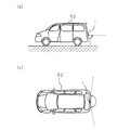
以下、本発明をその実施の形態を示す図面に基づき具体的に説明する。図1は、本発明に係る撮像装置が車両に搭載された場合の撮像範囲を示す模式図であり、(a)に車両の側面視を示し、(b)に車両の上面視を示してある。図において1は、車両50の背面に搭載された撮像装置であり、車両50の後方の路面及びその周辺を撮像し、車両50内の運転席近傍に配設されたディスプレイ(図示せず)に撮像した画像を表示することができるようにしてある。これにより、車両50を駐車場に駐車するときなど、車両を後退させるときに、駐車場の枠をなす白線の位置を確認することができるため、車両50の駐車を簡単に行うことができ、また、車両50の後方の歩行者又は障害物等の有無を確認できるため、事故の発生を防止することができるという利点がある。
Hereinafter, the present invention will be specifically described with reference to the drawings showing embodiments thereof. FIG. 1 is a schematic diagram showing an imaging range when the imaging apparatus according to the present invention is mounted on a vehicle, where (a) shows a side view of the vehicle and (b) shows a top view of the vehicle. . In the figure,
撮像装置1は、車両50の背面の約1m前後の高さの位置に搭載される。この場合、車両50の垂直方向(縦方向)での撮像装置1の撮像範囲は、撮像装置1の略直下の路面から、撮像装置1の搭載位置の高さ程度までの範囲(図1(a)の破線及び矢印参照)であり、縦方向の撮像装置1の画角は略90°程度にしてある。また、車両50の水平方向(横方向)での撮像装置1の撮像範囲は、車両50の背面に沿って左右の側方までの範囲に達しており(図1(b)の破線及び矢印参照)、横方向の撮像装置1の画角は略180°程度にしてある。このように、撮像装置1は、横方向の画角が縦方向の画角の2倍程度にしてある。
The
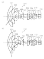
図2は、本発明に係る撮像装置1の構成を示す模式的断面図であり、(a)には撮像装置1の縦方向での断面を示し、(b)には横方向での断面を示してある。撮像装置1は、10個のレンズと、絞り120と、フィルタ125とにより構成されたアナモルフィック光学系100を備えており、アナモルフィック光学系100により結像された像を撮像素子130にて撮像するようにしてある。アナモルフィック光学系100には、第1レンズ101〜第10レンズ110の10個のガラス製のレンズが光線の入射側から撮像素子130までの間に、この順番で光軸を略揃えて並べて配設してある。絞り120は、第5レンズ105及び第6レンズ106の間に配設してあり、フィルタ125は、第10レンズ110及び撮像素子130の間に配設してある。
2A and 2B are schematic cross-sectional views showing the configuration of the
アナモルフィック光学系100の第1レンズ101、第2レンズ102、第5レンズ105、第7レンズ107、第8レンズ108、第9レンズ109及び第10レンズ110の7個のレンズは、光軸に直交する縦方向及び横方向の曲率が等しい曲面を両面に有するレンズである。第1レンズ101以外の6個のレンズは、平面形状が略円形をなしている。また、第3レンズ103、第4レンズ104及び第6レンズ106の3個のレンズは、縦方向及び横方向の曲率が異なる曲面、所謂アナモルフィック面を有するレンズである。
Seven lenses of the
第1レンズ101は、撮像装置1の最も入射側に配されたレンズであり、入射側の一面が凸面に形成され、他面が凹面に形成されたレンズ、所謂メニスカスレンズである。ただし、詳細は後述するが、第1レンズ101は、平面形状が非円形であり、略小判形をなしている。第2レンズ102は、入射側の一面が凸面に形成され、他面が凹面に形成されたメニスカスレンズである。第2レンズ102は、第1レンズ101より径の小さいレンズであり、平面形状が円形をなしている。
The
第3レンズ103は、入射側の一面が縦方向及び横方向に曲率が等しい凸面に形成され、他面が縦方向及び横方向に曲率が若干異なる凹状のアナモルフィック面に形成されたレンズ、所謂アナモルフィックレンズである。第4レンズ104もまたアナモルフィックレンズであり、入射側の一面が横方向にのみ凹状に曲げられたアナモルフィック面に形成してあり、他面が縦方向及び横方向に曲率が等しい凹面に形成してある。第3レンズ103の他面及び第4レンズ104の一面の作用により、アナモルフィック光学系100の縦方向及び横方向の倍率が異なるものとなるようにしてある。
The
第5レンズ105は、入射側の一面が平面に形成され、他面が凸面に形成された凸レンズである。また、第5レンズ105の他面側には、板部材の中央に開口が形成された絞り120が、第5レンズ105の他面の周縁部分に当接するように設けられている。絞り120の開口は略楕円形又は略小判形をなしており、第5レンズ105から出射した不要な光が第6レンズ106へ入射することを防止している。これにより、撮像素子130により撮像される画像の彩度を高めることができる。
The
第6レンズ106は、入射側の一面が縦方向にのみ凹状に曲げられたアナモルフィック面に形成され、他面が横方向にのみ凸状に曲げられたアナモルフィック面に形成されたアナモルフィックレンズである。第6レンズ106によって、更に縦方向及び横方向の倍率を調整するようにしてある。
The
第7レンズ107は、両面が縦方向及び横方向に曲率が等しい凸面に形成された凸レンズであり、第8レンズ108は、入射側の一面が縦方向及び横方向に曲率が等しい凹面に形成され、他面が縦方向及び横方向に曲率が等しい凸面に形成されたメニスカスレンズである。第7レンズ107の他面及び第8レンズ108の一面の曲率は等しくしてあり、第7レンズ107及び第8レンズ108は接合して配されている。即ち、第7レンズ107及び第8レンズ108は、接合レンズをなしている。
The
第9レンズ109は、入射側の一面が縦方向及び横方向に曲率が等しい凸面に形成され、他面が縦方向及び横方向に曲率が等しい凹面に形成されたメニスカスレンズであり、第10レンズ110は、両面が縦方向及び横方向に曲率が等しい凸面に形成された凸レンズである。第9レンズ109の他面及び第10レンズ110の一面の曲率は等しくしてあり、第9レンズ109及び第10レンズ110は接合して配されている。第9レンズ109及び第10レンズ110もまた、接合レンズをなしている。
The
第10レンズ110から出射した光は、フィルタ125を通して撮像素子130へ集光されるようにしてある。フィルタ125は、赤外線をカットする機能を有すると共に、撮像素子130の撮像面に当接して設けられ、撮像素子130を保護する部材としての機能を有している。撮像素子130は、CCD又はCMOS等によるイメージセンサにより受光した光を電気信号に変換して出力する素子であり、撮像素子130が出力する電気信号をサンプリングしてデジタルデータに変換することによって、撮像装置1は画像データを取得するようにしてある。
The light emitted from the
図3は、アナモルフィック光学系を用いた撮像装置とその他の光学系を用いた撮像装置との相違を説明するための模式図であり、撮像装置の入射側の平面視、即ち最も入射側のレンズの平面視を模式的に図示したものである。また、図中には、レンズLに対して、撮像装置の撮像素子へ結像する光が通過する有効領域Aと、撮像素子へ結像する光が通過しない無効領域Bとが図示してあり、(a)にアナモルフィック光学系の場合を図示し、(b)にその他の光学系、即ちアナモルフィック光学系でない光学系の場合を図示してある。 FIG. 3 is a schematic diagram for explaining the difference between an imaging apparatus using an anamorphic optical system and an imaging apparatus using another optical system, and is a plan view on the incident side of the imaging apparatus, that is, the most incident side. FIG. 2 schematically shows a plan view of the lens. In the drawing, an effective area A through which light focused on the image sensor of the imaging device passes and an invalid area B through which light focused on the image sensor does not pass are illustrated for the lens L. (A) illustrates the case of an anamorphic optical system, and (b) illustrates the case of another optical system, that is, an optical system that is not an anamorphic optical system.
撮像装置にアナモルフィック光学系が用いられていない場合(図3(b)参照)、有効領域Aは縦方向及び横方向の比が、撮像素子の撮像面(CCD又はCMOS等のイメージセンサがマトリクス状に配された有効画素領域)の縦方向及び横方向の比に一致する。換言すれば、有効領域Aは、撮像装置の撮像素子のレンズLに写る像に等しいものであり、レンズLに写る像の縦方向及び横方向の比は、実際の撮像素子の縦方向及び横方向の比に等しくなる。 When an anamorphic optical system is not used in the image pickup apparatus (see FIG. 3B), the effective area A has a ratio between the vertical direction and the horizontal direction, and the image pickup surface (an image sensor such as a CCD or CMOS) This corresponds to the ratio between the vertical direction and the horizontal direction of the effective pixel regions arranged in a matrix. In other words, the effective area A is equal to the image captured on the lens L of the image sensor of the imaging apparatus, and the ratio between the vertical direction and the horizontal direction of the image captured on the lens L is the actual vertical and horizontal ratio of the image sensor. Equal to the ratio of directions.
撮像装置にアナモルフィック光学系が用いられている場合(図3(a)参照)、縦方向及び横方向で倍率が異なるため、有効領域Aの縦方向及び横方向の比は、撮像素子の撮像面の縦方向及び横方向の比に一致しない。このため、有効領域Aは、例えば横方向に引き伸ばされ、縦方向に縮められた略矩形の領域となる。この場合、有効領域Aの縦方向の両側に位置する無効領域Bは、図3(b)の場合と比較して面積が大きく、逆に有効領域Aの横方向の両側に位置する無効領域Bは、図3(b)の場合と比較して面積が小さい。 When an anamorphic optical system is used in the imaging apparatus (see FIG. 3A), since the magnification is different in the vertical direction and the horizontal direction, the ratio of the effective area A in the vertical direction and the horizontal direction is It does not coincide with the ratio between the vertical direction and the horizontal direction of the imaging surface. Therefore, the effective area A is, for example, a substantially rectangular area that is expanded in the horizontal direction and contracted in the vertical direction. In this case, the invalid area B located on both sides of the effective area A in the vertical direction has a larger area than that in the case of FIG. 3B, and conversely, the invalid area B located on both sides of the effective area A in the horizontal direction. Is smaller in area than the case of FIG.
図4は、本発明に係る撮像装置1の第1レンズ101の構成を示す模式図であり、(a)に第1レンズ101の正面視を示し、(b)に縦方向の断面を示し、(c)に横方向の断面を示してある。図4(a)に示すように、第1レンズ101は、平面視で円形をなしておらず、略小判形をなしている。この形状は、図3(a)に示した有効領域Aの縦方向の両側に位置する無効領域Bを切り欠いた形状であり、これにより第1レンズ101の縦方向の幅は第2レンズ102の直径に略等しくなるようにしてある(図2(a)参照)。
FIG. 4 is a schematic diagram illustrating the configuration of the
以上の構成の撮像装置1においては、アナモルフィック光学系100の最も入射側の構成要素をなすメニスカスレンズの第1レンズ101の形状を、平面形状が円形でなく、撮像素子130へ結像する光が通過しない無効領域を切り欠いた非円形の略小判形とすることによって、第1レンズ101を縦方向に小型化でき、アナモルフィック光学系100を小型化できるため、撮像装置1を小型化することが可能となる。
In the
また、第1レンズ101〜第10レンズ110をガラス製のレンズとすることによって、ガラス製のレンズは耐久性に優れるため、レンズが破損する虞が少なく、撮像装置1の信頼性を高めることができる。特に、最も入射側の第1レンズ101をガラス製とすることで、撮像装置1の耐久性を効果的に高めることができる。また、ガラス製のレンズは屈折率が高いため、撮像装置1の撮像範囲をより広くすることができる。
Moreover, since the glass lens is excellent in durability by using the
なお、本実施の形態においては、アナモルフィック光学系100の第1レンズ101の形状のみを非円形としたが、これに限るものではなく、例えば、更に第2レンズ102の形状を、撮像素子130へ結像する光が通過しない無効領域を切り欠いて非円形としてもよく、この場合には撮像装置1をより小型化することが可能となる。また、第1レンズ101の縦方向の両側の無効領域を切り欠いて略小判形とする構成としたが、これに限るものではなく、横方向の両側の無効領域を更に切り欠いて、平面形状が略矩形のレンズとしてもよい。
In the present embodiment, only the shape of the
また、第1レンズ101〜第10レンズ110をガラス製のレンズとしたが、これに限るものではなく、合成樹脂(プラスチック)製のレンズであってもよい。合成樹脂製のレンズは製造が容易であるため、製造コストが低減でき、撮像装置1のコストを低減できるという利点がある。また、第1レンズ101〜第10レンズ110は全て同じ材料で形成する必要はなく、ガラス製のレンズと合成樹脂製のレンズとを混在させてもよい。
In addition, although the
また、図2に示したアナモルフィック光学系100の構成、即ち光学系を構成するレンズの種類及び配置等は、一例であってこれに限るものではない。例えば、第1レンズ101をメニスカスレンズとしたが、これに限るものではなく、凸レンズ又は凹レンズ等であってもよい。また、図1において、撮像装置1は車両50の背面に搭載する構成としたが、これに限るものではなく、車両の前面又は側面等に搭載する構成であってもよい。
Further, the configuration of the anamorphic
1 撮像装置
100 アナモルフィック光学系
101 第1レンズ(等曲面レンズ)
102 第2レンズ(等曲面レンズ)
103 第3レンズ(アナモルフィックレンズ)
104 第4レンズ(アナモルフィックレンズ)
105 第5レンズ(等曲面レンズ)
106 第6レンズ(アナモルフィックレンズ)
107 第7レンズ(等曲面レンズ)
108 第8レンズ(等曲面レンズ)
109 第9レンズ(等曲面レンズ)
110 第10レンズ(等曲面レンズ)
120 絞り
125 フィルタ
130 撮像素子
DESCRIPTION OF
102 Second lens (Iso-curved lens)
103 Third lens (anamorphic lens)
104 4th lens (anamorphic lens)
105 Fifth lens (Isocurved lens)
106 6th lens (anamorphic lens)
107 7th lens (Isocurved lens)
108 Eighth lens (Isocurved lens)
109 9th lens (Isocurved lens)
110 10th lens (Isocurved lens)
120
Claims (7)
該アナモルフィック光学系により結像された像を撮像する撮像素子と
を備える撮像装置において、
前記等曲面レンズの形状が、前記撮像素子に結像する光線が通過しない領域を切り欠いた非円形であること
を特徴とする撮像装置。 An anamorphic lens having an anamorphic surface having different curvatures in two directions orthogonal to the optical axis and orthogonal to each other, and an isosurface lens having a curved surface having the same curvature in the two directions, and the magnification in the two directions Different anamorphic optics,
In an imaging apparatus comprising: an imaging element that captures an image formed by the anamorphic optical system;
The imaging apparatus, wherein the shape of the iso-curved lens is a non-circular shape in which a region where a light beam focused on the imaging element does not pass is cut out.
最も入射側に配された等曲面レンズの形状が、前記非円形にしてある請求項1に記載の撮像装置。 The anamorphic optical system has a plurality of isosurface lenses, and a plurality of isosurface lenses are arranged coaxially,
The imaging apparatus according to claim 1, wherein a shape of an isosurface lens arranged closest to the incident side is the non-circular shape.
前記等曲面レンズの形状が、前記被結像体に結像する光線が通過しない領域を切り欠いた非円形であること
を特徴とする光学装置。 An anamorphic lens having an anamorphic surface having different curvatures in two directions orthogonal to the optical axis and orthogonal to each other, and an isosurface lens having a curved surface having the same curvature in the two directions, and different magnifications in the two directions In an optical device that forms an image on an object with
An optical device, wherein the shape of the iso-curved lens is a non-circular shape in which a region through which a light beam that forms an image on the object to be imaged does not pass.
前記被結像体に結像する光線が通過しない領域を切り欠いた非円形の形状であること
を特徴とするレンズ。 In a lens that has a curved surface having the same curvature in two directions perpendicular to the optical axis and perpendicular to each other,
A lens having a non-circular shape in which a region through which a light beam that forms an image on the object does not pass is cut out.
Priority Applications (1)
| Application Number | Priority Date | Filing Date | Title |
|---|---|---|---|
| JP2006157471A JP2007328030A (en) | 2006-06-06 | 2006-06-06 | Imaging apparatus, optical device and lens |
Applications Claiming Priority (1)
| Application Number | Priority Date | Filing Date | Title |
|---|---|---|---|
| JP2006157471A JP2007328030A (en) | 2006-06-06 | 2006-06-06 | Imaging apparatus, optical device and lens |
Publications (1)
| Publication Number | Publication Date |
|---|---|
| JP2007328030A true JP2007328030A (en) | 2007-12-20 |
Family
ID=38928561
Family Applications (1)
| Application Number | Title | Priority Date | Filing Date |
|---|---|---|---|
| JP2006157471A Pending JP2007328030A (en) | 2006-06-06 | 2006-06-06 | Imaging apparatus, optical device and lens |
Country Status (1)
| Country | Link |
|---|---|
| JP (1) | JP2007328030A (en) |
Cited By (11)
| Publication number | Priority date | Publication date | Assignee | Title |
|---|---|---|---|---|
| EP2172797A1 (en) | 2008-10-01 | 2010-04-07 | Kabushiki Kaisha Topcon | Anamorphic optical system, image pickup device, on-board type camera and monitoring camera |
| JP2010128435A (en) * | 2008-12-01 | 2010-06-10 | Rohm Co Ltd | Camera apparatus |
| JP2010134286A (en) * | 2008-12-05 | 2010-06-17 | Sharp Corp | Combined lens, imaging apparatus, and electronic equipment |
| CN101900868A (en) * | 2009-05-27 | 2010-12-01 | 柯尼卡美能达精密光学株式会社 | Anamorphic lens |
| JP2011022444A (en) * | 2009-07-17 | 2011-02-03 | Panasonic Corp | Cemented optical element |
| JP2011237672A (en) * | 2010-05-12 | 2011-11-24 | Ricoh Co Ltd | Imaging apparatus |
| CN106094172A (en) * | 2016-08-25 | 2016-11-09 | 厦门爱劳德光电有限公司 | A kind of 5,000,000 pixel fish eye lenses |
| CN106226889A (en) * | 2016-08-25 | 2016-12-14 | 厦门爱劳德光电有限公司 | A kind of 12,000,000 pixel fish eye lenses |
| EP3779552A4 (en) * | 2018-03-28 | 2021-05-19 | Panasonic Intellectual Property Management Co., Ltd. | Lens system, imaging device, and imaging system |
| KR20220093576A (en) * | 2020-12-28 | 2022-07-05 | 삼성전기주식회사 | Lens and Optical Imaging System |
| US11442256B2 (en) * | 2018-11-14 | 2022-09-13 | Largan Precision Co., Ltd. | Imaging optical lens assembly, imaging apparatus and electronic device |
Citations (2)
| Publication number | Priority date | Publication date | Assignee | Title |
|---|---|---|---|---|
| JPS6187125A (en) * | 1984-09-20 | 1986-05-02 | Canon Inc | Projecting device for exposing slit |
| JP2006011093A (en) * | 2004-06-25 | 2006-01-12 | Konica Minolta Opto Inc | Super wide angle optical system, imaging apparatus, on-vehicle camera and digital equipment |
-
2006
- 2006-06-06 JP JP2006157471A patent/JP2007328030A/en active Pending
Patent Citations (2)
| Publication number | Priority date | Publication date | Assignee | Title |
|---|---|---|---|---|
| JPS6187125A (en) * | 1984-09-20 | 1986-05-02 | Canon Inc | Projecting device for exposing slit |
| JP2006011093A (en) * | 2004-06-25 | 2006-01-12 | Konica Minolta Opto Inc | Super wide angle optical system, imaging apparatus, on-vehicle camera and digital equipment |
Cited By (19)
| Publication number | Priority date | Publication date | Assignee | Title |
|---|---|---|---|---|
| JP4669539B2 (en) * | 2008-10-01 | 2011-04-13 | 株式会社トプコン | Imaging device, in-vehicle camera, and surveillance camera |
| JP2010085849A (en) * | 2008-10-01 | 2010-04-15 | Topcon Corp | Image capturing apparatus, on-board camera and monitoring camera |
| EP2172797A1 (en) | 2008-10-01 | 2010-04-07 | Kabushiki Kaisha Topcon | Anamorphic optical system, image pickup device, on-board type camera and monitoring camera |
| US7940469B2 (en) | 2008-10-01 | 2011-05-10 | Kabushiki Kaisha Topcon | Anamorphic optical system, image pickup device, on-board type camera and monitoring camera |
| JP2010128435A (en) * | 2008-12-01 | 2010-06-10 | Rohm Co Ltd | Camera apparatus |
| JP2010134286A (en) * | 2008-12-05 | 2010-06-17 | Sharp Corp | Combined lens, imaging apparatus, and electronic equipment |
| CN101900868A (en) * | 2009-05-27 | 2010-12-01 | 柯尼卡美能达精密光学株式会社 | Anamorphic lens |
| EP2259119A1 (en) * | 2009-05-27 | 2010-12-08 | Konica Minolta Opto, Inc. | Anamorphic lens |
| US8049967B2 (en) | 2009-05-27 | 2011-11-01 | Konica Minolta Opto, Inc. | Anamorphic lens |
| JP2011022444A (en) * | 2009-07-17 | 2011-02-03 | Panasonic Corp | Cemented optical element |
| JP2011237672A (en) * | 2010-05-12 | 2011-11-24 | Ricoh Co Ltd | Imaging apparatus |
| CN106094172A (en) * | 2016-08-25 | 2016-11-09 | 厦门爱劳德光电有限公司 | A kind of 5,000,000 pixel fish eye lenses |
| CN106226889A (en) * | 2016-08-25 | 2016-12-14 | 厦门爱劳德光电有限公司 | A kind of 12,000,000 pixel fish eye lenses |
| EP3779552A4 (en) * | 2018-03-28 | 2021-05-19 | Panasonic Intellectual Property Management Co., Ltd. | Lens system, imaging device, and imaging system |
| US11880022B2 (en) | 2018-03-28 | 2024-01-23 | Panasonic Intellectual Property Management Co., Ltd. | Lens system, imaging device, and imaging system including a lens element having a free-curve surface |
| US11442256B2 (en) * | 2018-11-14 | 2022-09-13 | Largan Precision Co., Ltd. | Imaging optical lens assembly, imaging apparatus and electronic device |
| KR20220093576A (en) * | 2020-12-28 | 2022-07-05 | 삼성전기주식회사 | Lens and Optical Imaging System |
| KR102536605B1 (en) * | 2020-12-28 | 2023-05-26 | 삼성전기주식회사 | Lens and Optical Imaging System |
| US11927731B2 (en) | 2020-12-28 | 2024-03-12 | Samsung Electro-Mechanics Co., Ltd. | Lens and optical imaging system |
Similar Documents
| Publication | Publication Date | Title |
|---|---|---|
| JP2007328030A (en) | Imaging apparatus, optical device and lens | |
| JP4516475B2 (en) | Imaging optical system for an endoscope having a substantially spherical observation window | |
| KR100804719B1 (en) | Imaging module | |
| US7538956B2 (en) | Panoramic imaging device | |
| JP2008176183A (en) | Imaging lens and imaging apparatus with same | |
| JP2006267391A (en) | Imaging apparatus | |
| JP2006337691A (en) | Image-formation optical system | |
| JP2008233610A (en) | Imaging lens and imaging device equipped with the imaging lens | |
| JP2009092797A (en) | Imaging lens and imaging device | |
| JP2009031762A (en) | Imaging lens and imaging device | |
| JP2008292800A (en) | Anamorphic lens, imaging apparatus and supervising device | |
| JP2004312239A (en) | Image pickup device | |
| JP2010145828A (en) | Imaging lens | |
| US7116351B2 (en) | Imaging device | |
| JP2008139755A5 (en) | ||
| JP2008083398A (en) | Compound-eye optics and optical apparatus using the same | |
| US20220050260A1 (en) | Imaging lens assembly, image capturing device and electronic device | |
| TWI741790B (en) | Imaging lens system, image capturing unit and electronic device | |
| KR100951187B1 (en) | Camera module | |
| WO2015075951A1 (en) | Lens unit, image-capturing device, and vehicle-mounted camera | |
| JP4527363B2 (en) | In-vehicle camera device | |
| TWI762355B (en) | Image capturing unit, camera module and electronic device | |
| JP2007043392A (en) | Vehicle mount imaging apparatus and on-vehicle camera system | |
| JP2010072032A (en) | Imaging lens and camera module | |
| KR100959165B1 (en) | compact imaging lens |
Legal Events
| Date | Code | Title | Description |
|---|---|---|---|
| A621 | Written request for application examination |
Free format text: JAPANESE INTERMEDIATE CODE: A621 Effective date: 20090113 |
|
| A977 | Report on retrieval |
Free format text: JAPANESE INTERMEDIATE CODE: A971007 Effective date: 20110819 |
|
| A131 | Notification of reasons for refusal |
Free format text: JAPANESE INTERMEDIATE CODE: A131 Effective date: 20110830 |
|
| A02 | Decision of refusal |
Free format text: JAPANESE INTERMEDIATE CODE: A02 Effective date: 20111227 |