JP2007323173A - Control equipment and monitor control system - Google Patents
Control equipment and monitor control system Download PDFInfo
- Publication number
- JP2007323173A JP2007323173A JP2006150199A JP2006150199A JP2007323173A JP 2007323173 A JP2007323173 A JP 2007323173A JP 2006150199 A JP2006150199 A JP 2006150199A JP 2006150199 A JP2006150199 A JP 2006150199A JP 2007323173 A JP2007323173 A JP 2007323173A
- Authority
- JP
- Japan
- Prior art keywords
- control
- control device
- logic
- wireless communication
- devices
- Prior art date
- Legal status (The legal status is an assumption and is not a legal conclusion. Google has not performed a legal analysis and makes no representation as to the accuracy of the status listed.)
- Pending
Links
Images


Classifications
-
- Y—GENERAL TAGGING OF NEW TECHNOLOGICAL DEVELOPMENTS; GENERAL TAGGING OF CROSS-SECTIONAL TECHNOLOGIES SPANNING OVER SEVERAL SECTIONS OF THE IPC; TECHNICAL SUBJECTS COVERED BY FORMER USPC CROSS-REFERENCE ART COLLECTIONS [XRACs] AND DIGESTS
- Y02—TECHNOLOGIES OR APPLICATIONS FOR MITIGATION OR ADAPTATION AGAINST CLIMATE CHANGE
- Y02P—CLIMATE CHANGE MITIGATION TECHNOLOGIES IN THE PRODUCTION OR PROCESSING OF GOODS
- Y02P90/00—Enabling technologies with a potential contribution to greenhouse gas [GHG] emissions mitigation
- Y02P90/02—Total factory control, e.g. smart factories, flexible manufacturing systems [FMS] or integrated manufacturing systems [IMS]
Abstract
Description
本発明は、制御機器を監視・制御することによりプラントを運転する監視制御システムに係り、特に水力・火力・原子力発電プラントにおいて各制御機器を監視・制御するに好適な監視制御システム及びそのシステムに適用される制御機器に関する。 The present invention relates to a monitoring control system for operating a plant by monitoring and controlling the control equipment, and particularly to a monitoring control system suitable for monitoring and controlling each control equipment in a hydropower, thermal power, and nuclear power plant, and the system thereof. It relates to the applied control equipment.
発電プラントにおいては、中央制御室にオペレーション装置やサーバなどの電子計算機を配置し、これらをネットワークを介して主タービン制御装置やボイラローカル制御装置などの制御装置に接続して、オペレーション装置からの操作指令あるいは制御装置からの制御指令に基づいて各種制御機器を動作させるシステムが構築されている。オペレーション装置は、プラントの運転に必要な操作・監視機能を備えたヒューマンマシンインタフェース装置で、運転員の要求に基づき各制御機器に対する指令を制御装置に出力するとともに、プラント情報をディスプレイなどの表示装置へ表示することにより、各種制御情報の提供およびガイダンスの出力等を行う。サーバは、プラント全体の運用に関する情報処理を行い、各制御装置に対する運転、停止などの指令を生成する。 In power plants, computers such as operation devices and servers are installed in the central control room, and these are connected to control devices such as the main turbine control device and boiler local control device via the network, so that operations from the operation device can be performed. A system for operating various control devices based on a command or a control command from a control device has been constructed. The operation device is a human-machine interface device equipped with operation and monitoring functions necessary for plant operation. Based on the operator's request, the operation device outputs commands to each control device to the control device, and the plant information is displayed on a display device such as a display. By displaying the screen, various control information is provided and guidance is output. The server performs information processing related to the operation of the entire plant, and generates commands such as operation and stop for each control device.
制御装置は、オペレーション装置からの操作指令やサーバで生成された運転、停止などの指令を基に、各種制御機器に対して起動や停止、あるいは制御量の調整などの指令を出力したり、計測機器で計測されたセンサ検出値などを入力したりするプロセス入出力装置を備えている。このプロセス入出力装置と各種制御機器、例えば電動弁や電磁弁などのバルブ、ポンプ、モータ、アクチュエータ等との間は有線で接続されており、小規模な発電プラントでも、そのケーブルの数は数万本に上り、建設コストの大きな部分を占めている。 Based on the operation commands from the operation device and the commands generated by the server, such as operation and stop, the control device outputs commands such as start and stop, adjustment of control amount, etc. A process input / output device is provided for inputting sensor detection values measured by equipment. This process input / output device and various control devices, such as valves such as motorized valves and solenoid valves, pumps, motors, actuators, etc. are connected by wire, and even in a small power plant, the number of cables is several. The number is 10,000, accounting for a large part of the construction cost.
そこで、近年ではコスト削減のため、制御装置と制御機器間を有線で接続する代わりにフィールドバスで接続し、伝送を行う方法が普及し始めている。あるフィールドバス規格では1本のケーブル(セグメント)で双方向かつ32個の制御および計測機器の信号を伝送できるので、従来の有線でのプロセス入出力方式と比較してケーブル数量を大幅に削減することができる。ケーブル数量の削減により、ケーブル敷設コストを削減できるだけでなく、制御装置に組み込む入出力装置の数も削減できるため、制御装置を小型化することができ、中央制御室の構成を簡素化できる。 Therefore, in recent years, in order to reduce costs, a method of performing transmission by connecting a control device and a control device by a field bus instead of connecting by wire has started to spread. A certain fieldbus standard can transmit signals from 32 control and measurement devices bidirectionally with a single cable (segment), greatly reducing the number of cables compared to conventional wired process input / output methods. be able to. By reducing the number of cables, not only the cable laying cost can be reduced, but also the number of input / output devices incorporated in the control device can be reduced, so that the control device can be reduced in size and the configuration of the central control room can be simplified.
また、複数の制御機器に対する制御指令を出力したり、複数の制御機器の状態に関する情報を入力する配電盤開閉装置を制御装置に接続することにより、敷設するケーブルの数を削減するとともに、装置の簡素化を図ることができる監視制御システムもある。 In addition, the number of cables to be laid can be reduced by connecting a switchboard switchgear that outputs control commands for a plurality of control devices and inputs information on the status of the plurality of control devices to the control device. There is also a supervisory control system that can be realized.
特許文献1には、制御装置と配電盤開閉装置とをシリアルケーブルを介して接続し、配電盤開閉装置が複数の制御機器の監視・制御を行う監視制御システムの例についての開示がある。
上記従来技術のフィールドバス方式においては、制御装置と制御機器間をフィールドバスで接続することにより、プロセス入出力方式と比較してケーブル数量を削減できる。しかしながら、フィールドバスの場合、セグメントのある1箇所で断線などの故障が発生すると、その故障箇所から下流側(機器側)に接続している制御機器、計測機器との伝送がすべて途絶えてしまうという問題がある。そのため、発電所などのプラントでは、その信頼性、安定供給責務の観点から、重要な制御系統には使用されず、普及が進んでいない。それゆえに、入出力点数が数万点にのぼる大規模火力発電所などにおいても、重要度の低い系統にしかフィールドバスを適用できず、敷設ケーブル数が依然多いという問題点がある。 In the above-described field bus system of the prior art, the number of cables can be reduced as compared with the process input / output system by connecting the control device and the control device by a field bus. However, in the case of a fieldbus, if a failure such as disconnection occurs at one segment, transmission from the failure to the control device and measurement device connected downstream (device side) will be interrupted. There's a problem. For this reason, plants such as power plants are not used in important control systems and are not widely used from the viewpoint of reliability and stable supply responsibility. Therefore, even in a large-scale thermal power plant having tens of thousands of input / output points, there is a problem that the fieldbus can be applied only to a less important system, and the number of installed cables is still large.
また、従来の制御機器は、複雑な処理を行うための手段を備えていないため、各制御機器の制御、保護ロジックは制御装置側に定義し、演算処理を行っていた。更に、従来のフィールドバス方式では、1つのセグメントに接続できる制御、計測機器の数が限られている上に、1つの制御機器が制御装置および他の制御機器との間でやりとりできる信号の数も多くなかった。そのため、ある制御機器の制御、保護論理に必要な保護インターロック条件が他セグメントに属していることもあり、その場合、制御装置を経由してその情報を得る必要があった。従って、制御機器側ではごく簡単なロジックしか実現できず、制御機器の主な制御、保護ロジックは制御装置側で組むことになり、制御装置を自律分散化することができなかった。 In addition, since the conventional control device does not include a means for performing complicated processing, the control and protection logic of each control device is defined on the control device side to perform arithmetic processing. Furthermore, in the conventional fieldbus system, the number of control and measurement devices that can be connected to one segment is limited, and the number of signals that one control device can exchange with the control device and other control devices. There weren't many. Therefore, a protection interlock condition necessary for control and protection logic of a certain control device may belong to another segment, and in that case, it is necessary to obtain the information via a control device. Therefore, only a very simple logic can be realized on the control device side, and the main control and protection logic of the control device is assembled on the control device side, and the control device cannot be distributed autonomously.
特許文献1の監視制御システムにおいても、配電盤開閉装置と制御機器間はプロセスケーブルで接続しているため、ケーブル数は依然として多いままである。また、制御、保護ロジックとそれらに必要な保護インターロック条件などの情報は配電盤開閉装置側に定義してあり、保護インターロックに関する監視情報を基にした制御指令などの情報は、配電盤開閉装置側で演算処理して生成するなど、保護インターロックに関しては自律分散化しているが、制御装置からの指令なしで制御が行なえるほどの自律分散化は行われていない。更に、制御装置と各配電盤開閉装置はシリアル伝送ケーブルでカスケード接続しているため、シリアル伝送ケーブルのある1ヶ所が断線したりあるいは配電盤開閉装置に故障が発生したりすると、その断線あるいは故障箇所から下流側(配電盤開閉装置側)に接続してある配電盤開閉装置と制御装置との伝送が全て途絶えてしまうという問題がある。
Also in the monitoring control system of
更に、近年、プラント規模の大型化や制御システムの高度化に伴い、制御装置の入出力点数が増加する傾向にあるため、設置コストが増大するとともに、装置や機器の増設に関しても容易に対応できるシステムが求められている。 Furthermore, with the recent increase in plant scale and control system sophistication, the number of input / output points of the control device tends to increase, which increases the installation cost and can easily cope with the expansion of devices and equipment. A system is needed.
本発明はかかる点に鑑みてなされたものであり、制御装置と制御、計測機器間を無線化し、制御、計測機器側において制御、保護演算を行う、自律分散型監視制御システムを提供することを目的とする。 The present invention has been made in view of the above points, and provides an autonomous distributed monitoring and control system that performs wireless control between a control device and control and measurement equipment, and performs control and protection calculations on the control and measurement equipment side. Objective.
本発明は、バルブ、ポンプ、モータ、アクチュエータ等の制御機器や計測機器に、制御装置や他の制御機器、計測機器などと無線により通信を行う無線通信手段と、制御、保護演算処理を行う演算回路とを備える。また、演算回路には、制御機器の状態を示すプロセスデータや計測機器の計測値を入力する状態入力手段と、無線通信手段を介して制御指令やプロセスデータなどの制御情報を入力または出力する無線制御情報入出力手段と、制御機器の保護インターロックあるいは制御ロジックの論理を格納する記憶手段と、記憶手段に格納した保護インターロックあるいは制御ロジックの論理と、制御装置からの制御指令と、当該制御機器及び関連する他の制御機器のプロセスデータとを基に制御信号を演算する演算手段と、演算手段によって演算した制御信号を制御機器に出力する制御信号出力手段とを備える。 The present invention relates to control devices such as valves, pumps, motors, actuators, and measurement devices, wireless communication means for wirelessly communicating with control devices, other control devices, measurement devices, etc. Circuit. In addition, the arithmetic circuit has a state input unit for inputting process data indicating the state of the control device and a measurement value of the measurement device, and a wireless unit for inputting or outputting control information such as a control command or process data via the wireless communication unit. Control information input / output means, storage means for storing the protection interlock or control logic logic of the control device, protection interlock or control logic logic stored in the storage means, a control command from the control device, and the control Computation means for computing a control signal based on the process data of the equipment and other related control equipment, and control signal output means for outputting the control signal computed by the computation means to the control equipment.
このように、制御機器や計測機器に演算回路を備えることによりプログラマブル化し、保護インターロックのロジックあるいは制御ロジックを組み込むことができる。また、ロジックに必要な他の制御機器の状態や計測データ等の情報を制御装置を経由せずに授受することにより、制御装置との無線通信が途切れた場合でも制御機器側のみで健全な制御を継続することができる。 As described above, the control device and the measurement device can be programmed by providing the arithmetic circuit, and the protection interlock logic or the control logic can be incorporated. In addition, by sending and receiving information such as the status of other control devices necessary for logic and measurement data without passing through the control device, even if wireless communication with the control device is interrupted, sound control can be performed only on the control device side. Can continue.
前記制御、計測機器を構成するに際しては、状態入力手段と制御信号出力手段と演算手段の内、少なくとも一つを多重化することが望ましい。 When configuring the control and measurement equipment, it is desirable to multiplex at least one of the state input means, the control signal output means, and the calculation means.
さらに、各制御、計測機器の無線通信手段に中継機能を備えることにより、通信ルートの一部が切断しても他のルートを迂回することによって通信可能とすることができる。 Further, by providing a relay function in the wireless communication means of each control and measuring device, even if a part of the communication route is disconnected, communication can be performed by bypassing the other route.
また、本発明は、制御装置に前記制御、計測機器との間で無線通信を行うための無線通信手段を搭載し、複数の制御装置と複数の制御、計測機器との間で無線LAN(Local Area Network)を構成し、制御、計測機器を監視・制御することによりプラントを運転する監視制御システムを構成する。 Further, the present invention includes a wireless communication means for performing wireless communication with the control and measurement device in the control device, and a wireless LAN (Local) between the plurality of control devices and the plurality of control and measurement devices. (Area Network) is configured, and a monitoring and control system for operating the plant is configured by monitoring and controlling the control and measuring devices.
また、制御機器に組み込む保護インターロックあるいは制御ロジックの論理(ロジックプログラム)を書き換え可能とし、ロジックプログラムのローディングやパラメータチューニング、データ模擬などを含むメンテナンスを行う保守装置を設ける。この保守装置に制御、計測機器との間で無線通信を行うための無線通信手段を搭載し、保守装置と制御、計測機器との間で無線通信を行うことにより、制御機器に組み込むロジックプログラムのメンテナンスを実現できるように構成したものである。 In addition, a protective interlock incorporated in the control device or a logic (logic program) of the control logic can be rewritten, and a maintenance device for performing maintenance including logic program loading, parameter tuning, data simulation and the like is provided. This maintenance device is equipped with wireless communication means for wireless communication between the control and measurement equipment, and the logic program embedded in the control equipment by performing wireless communication between the maintenance device and the control and measurement equipment. It is configured to realize maintenance.
本発明によると、制御、計測機器と制御装置との接続を無線化することにより、ケーブルレスの構成にすることができるため、設備の小型化、簡素化やプラントの建設コスト低減を図ることができる。また、各制御、計測機器と制御装置との間を、個々に無線通信を行う網型ネットワークで接続することになるため、フィールドバスのように1箇所の通信の切断が他の機器に影響を与えることが無く、信頼性を上げることができる。 According to the present invention, since the connection between the control and measurement equipment and the control device can be made wireless, a cable-less configuration can be achieved, so that downsizing and simplification of facilities and reduction of plant construction costs can be achieved. it can. In addition, since each control / measurement device and the control device are connected by a network network that performs wireless communication individually, disconnection of communication at one location, like a field bus, affects other devices. Reliability can be improved without giving.
また、各制御、計測機器に演算回路を設けることでプログラマブル化し、保護インターロックあるいは制御ロジックを組み込むことにより自律分散化するため、制御装置との無線通信が途切れても安定した制御が継続できる。さらに、各制御、計測機器が無線通信の中継機能を有しているので、通信ルートの一部が切断しても他のルートを迂回することによって通信可能となり、通信障害を防ぐことができる。 In addition, since each control and measurement device is programmable by providing an arithmetic circuit and is autonomously distributed by incorporating a protective interlock or control logic, stable control can be continued even if wireless communication with the control device is interrupted. Furthermore, since each control and measuring device has a wireless communication relay function, even if a part of the communication route is disconnected, communication can be performed by bypassing another route, and communication failure can be prevented.
以下、本発明の一実施の形態を、添付図面を参照して説明する。図1は本発明の一実施の形態によるシステムの全体構成図である。図2は制御機器の一例である電動弁、図3は計測機器の一例である演算器内蔵センサの構成例を示すブロック図である。 Hereinafter, an embodiment of the present invention will be described with reference to the accompanying drawings. FIG. 1 is an overall configuration diagram of a system according to an embodiment of the present invention. FIG. 2 is a motor-operated valve which is an example of a control device, and FIG. 3 is a block diagram illustrating a configuration example of an arithmetic unit built-in sensor which is an example of a measurement device.
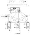
まず、図1を参照して本例の一実施の形態によるシステムの全体構成について説明する。本例は、オペレーション装置(以降OPSと称す)1、サーバ2、制御装置3と制御機器、計測機器から構成し、OPS1とサーバ2と制御装置3は、中央制御室などに設置され、それぞれネットワーク4を介して接続している。一般的に、制御装置3は制御系統毎に複数セット設置されるが、図1においては1セットのみ示している。OPS1はプラントの運転に必要な操作・監視機能を備えたヒューマンマシンインタフェース装置で、運転員の要求に基づき各制御機器に対する指令を制御装置3に出力するとともに、プラント情報をCRTなどの表示装置へ表示し、運転員に対する各種制御情報の提供およびガイダンスの出力等を行う。サーバ2はプラント全体の運用に関する情報処理を行い、制御装置3に対する運転、停止などの指令を出力する。制御装置3は、OPS1あるいはサーバ2からの指令をネットワーク4を介して入力し、制御、計測機器に対して出力する。なお、OPS1とサーバ2は必要に応じて設置されるもので、必ずしも必要ではない。
First, an overall configuration of a system according to an embodiment of the present example will be described with reference to FIG. This example is composed of an operation device (hereinafter referred to as OPS) 1, a
次に、制御装置3の構成について説明する。制御装置3は、CPU(Central Processing Unit)5と無線送受信機6を備え、CPU5と無線送受信機6は伝送路7を介して接続する。CPU5は、ネットワーク4に接続し、OPS1あるいはサーバ2から入力された指令を処理して複数の制御機器に対する制御指令を生成して出力し、無線送受信機6を介して各制御機器および計測機器からの情報を収集し、サーバ2などへ伝送するなどの処理を行う。無線送受信機6はCPU5が生成した制御指令を各制御機器へ出力したり、各制御機器および計測機器から出力されたデータを入力するなどの無線通信を行う。無線送受信機6は、複数個設置してもよく、無線送受信機6aのように制御装置3と離して設置してもよい。例えば制御、計測機器が複数のフロアに配置されている場合や、制御、計測機器が配置されているフィールドが広い場合など、設置環境に応じて適宜設置する。
Next, the configuration of the
制御、計測機器は、現場に設置され、制御装置3からの制御指令を基に電動弁やポンプなどの機器を動作させたり、制御機器の状態を示すプロセスデータや計測機器の計測値などの情報を制御装置3や他の制御、計測機器へ出力する。図1には、制御機器の例として、電動弁8、ポンプ10を、計測機器の例として、計測器9を示している。
Control and measurement equipment is installed at the site, operates equipment such as motorized valves and pumps based on control commands from the
次に、制御、計測機器の構成について説明する。電動弁8は、制御装置3および他の制御、計測機器との間で無線通信を行うための無線送受信機11と、保護または制御演算を行う演算回路21と、電動弁本体24から構成する。ポンプ10も同様に、無線送受信機13と、演算回路23と、ポンプ本体26から構成する。計測器9も同様に、無線送受信機12と、演算回路22と、センサ25から構成する。演算装置22は、センサ25が計測した計測値の変換や補正などの処理を行う。各制御、計測機器に備えた無線送受信機11、12、13は、制御装置3の無線送受信機6との間、および各制御、計測機器の無線送受信機間で制御指令やプロセスデータなどの伝送を無線通信により行う。
Next, the configuration of the control and measurement equipment will be described. The motor-operated valve 8 includes a radio transmitter /
また、本例では、制御、計測機器の演算回路に格納された制御論理や内部パラメータなどの情報を変更するための保守装置27を設けることができる。保守装置27は、パーソナルコンピュータや携帯情報端末などの計算機にメンテナンス機能を内蔵したものと、無線送受信機28から構成することができる。無線送受信機28を介してメンテナンス対象の制御、計測機器と通信を行うことにより、演算回路に格納された制御論理や内部パラメータなどの情報を書き換えることができる。また、内部パラメータのチューニングやデータ模擬などのメンテナンスも同様に無線送受信機を介して実施することが出来る。
In this example, a maintenance device 27 can be provided for changing information such as control logic and internal parameters stored in the arithmetic circuit of the control and measurement equipment. The maintenance device 27 can be composed of a computer such as a personal computer or a portable information terminal with a built-in maintenance function and a
次に、図2を参照して、制御機器の構成について更に説明する。図2は電動弁8の内部構成を示している。電動弁8は電動弁本体(モータおよびバルブ)24、無線送受信機11、演算回路21により構成する。演算回路21は、無線送受信機11によるデータの入出力処理を行うインターフェース31、保護あるいは制御演算を行うMPU(マイクロプロセッサユニット、Micro Processing Unit)32、RAM(ランダムアクセスメモリ、Random Access Memory)33、フラッシュメモリ34、プロセス入出力回路(PI/O)35を、BUS(バス)37で接続したものである。また、必要に応じて、プロセス入出力回路35にインターフェース回路36を内蔵した構成となっている。なお、上記演算回路21はパッケージ化されており、既設の通常の電動弁に対しても容易に取り付けることが出来るよう配慮されている。
Next, the configuration of the control device will be further described with reference to FIG. FIG. 2 shows the internal configuration of the motor-operated valve 8. The motor-operated valve 8 includes a motor-operated valve body (motor and valve) 24, a
電動弁8は、無線送受信機11を介して制御装置3あるいは他の制御機器、計測機器などから制御指令やプロセスデータを受け取る。また、プロセス入出力回路35は電動弁に関するプロセスデータである流量、弁開度、リミットスイッチなどの信号を電動弁本体24から入力する。不揮発性のフラッシュメモリ34には、電動弁に関する保護インターロックあるいは制御ロジックが保存されている。MPU32は、無線送受信機11、インターフェース31を介して入力した制御装置3からの制御指令と、他の制御、計測機器からのプロセスデータや、プロセス入出力回路35から得られた情報と、フラッシュメモリ34に保存されているロジックとから、制御指令を演算し、プロセス入出力回路35を介して電動弁本体24に対して制御指令を出力する。インターフェース回路36は、電動弁本体24の駆動に強電が必要な場合、プロセス入出力回路35の弱電出力を電動弁本体24の駆動に必要な電気信号に変換するなどの処理を行う。インターフェース回路36は、デジタル信号の変換の場合はフォトMOSリレーなどの素子や補助リレー、アナログ信号の変換の場合はアイソレータや電流アンプなどで構成する。
The motor-operated valve 8 receives control commands and process data from the
また、MPU32は、電動弁本体24から、電動弁に関するプロセスデータをインターフェース回路36、およびプロセス入出力回路35を介して入力し、フラッシュメモリ34に保存されている内部変数などを基に変換処理を行う。MPU32にて処理したプロセスデータは、インターフェース31、無線送受信機11を介して制御装置3あるいは他の制御機器、計測機器へ出力する。
Further, the
フラッシュメモリ34に格納されているロジックには、制御装置3との無線通信が切断した場合の論理、あるいは、他の制御機器、計測機器からの条件が入力できない場合の論理を必要に応じて組み込んでおく。例えば、制御装置3との通信が一定時間以上切断した場合は、制御装置3からの指令値を保持するなどのロジックを組んだり、他の制御、計測機器からのプロセスデータが入力されない場合は、直前に入力されたデータを保持して演算処理を行うなどのように定義しておく。これにより、無線通信が切断した場合でも、制御機器が制御不能の状態になることを防ぎ、プラントの運転を継続することができる。
The logic stored in the
ポンプ10など他の制御機器も、電動弁8とほぼ同じ構成とすることができ、電動弁本体24をポンプ本体(ポンプおよび電磁接触器など)26に置き換えるだけで、同様に構成できる。
Other control devices such as the
次に、図3を参照して計測機器の構成について説明する。図3は計測器9の内部構成を示している。計測器9は、無線送受信機12、演算回路22、センサ25、により構成する。演算回路22は電動弁8の演算回路21とほぼ同様であり、無線送受信機12によるデータの入出力処理を行うインターフェース41、計測値の変換や補正などの演算を行うMPU42、RAM43、フラッシュメモリ44、プロセス入出力回路(PI/O)45を、BUS(バス)47で接続したものである。このうち、プロセス入出力回路45は、センサ25からの入力方向のみであり、センサ25への出力はない。また、計測器9には、制御機器にあったインターフェース回路はない。上記演算回路22はパッケージ化されており、既設のセンサに対しても容易に取り付けることが出来るよう配慮されている。
Next, the configuration of the measuring device will be described with reference to FIG. FIG. 3 shows the internal configuration of the measuring instrument 9. The measuring instrument 9 includes a
MPU42では、センサ計測値の工学値変換や温度圧力補正などの演算を行うことができ、その演算プログラムは、不揮発性のフラッシュメモリ44に格納しておく。MPU42は、プロセス入出力回路45より入力したセンサ計測値に対し、フラッシュメモリ44に格納されている演算プログラムを基に演算処理を施し、その結果を無線送受信機12を介して、制御装置3あるいは他の制御機器8、10などに伝送する。
The
このように、本例においては、制御装置3が制御指令を出力すると、この指令が制御装置3の無線送受信機6を介して操作対象である制御、計測機器8〜10に無線通信により伝送されるため、制御装置3と制御、計測機器8〜10とをケーブルで接続する必要がなく、装置の簡素化を図ることができる。
In this way, in this example, when the
また、各制御機器(電動弁、ポンプ、アクチュエータなど)が、各々保護あるいは制御ロジックを内蔵し、演算に必要な外部の条件も制御装置3を経由せず自律的に得ることが出来るため、制御装置3と各制御機器との間で授受される指令は主に起動、停止あるいは制御量の調整などの指令のみである。このため、制御装置3と各制御機器との間の無線通信が途切れた場合でも、すぐに運転に支障が出ることはなく、特にプラントが一定運転をしている場合などにおいては、ある程度の時間であれば安定的に運転を継続することができる。更に、制御機器には、制御装置3や他の制御、計測機器との間の無線通信が途切れた場合の保護的なロジックを組み込んでおくことができるため、無線通信の一部が途切れることにより、制御機器に障害が発生し、プラントに異常を発生させることはない。
In addition, each control device (motorized valve, pump, actuator, etc.) has a built-in protection or control logic, and external conditions necessary for computation can be obtained autonomously without going through the
次に、本例による制御機器に組み込まれている保護インターロックあるいは制御ロジックや、計測機器に組み込まれている変換処理などの演算プログラムのメンテナンス方法について説明する。 Next, a description will be given of a maintenance method of a calculation program such as a protection interlock or control logic incorporated in the control device according to this example, and a conversion process incorporated in the measurement device.
図1に示すように、本例では、パーソナルコンピュータや携帯情報端末などの計算機にメンテナンス機能を内蔵した保守装置27に無線送受信機28を備え、メンテナンス対象の制御、計測機器と通信を行うことにより制御論理や内部パラメータなどの情報を変更することができる。保守装置27は、必要に応じてメンテナンス対象の機器と無線通信できる場所に設置すればよいため、保守員は中央制御室などの作業し易い場所や、場合によっては現場の制御、計測機器の近傍に出向くことでメンテナンス作業を行うことができる。
As shown in FIG. 1, in this example, a maintenance device 27 having a maintenance function built in a computer such as a personal computer or a portable information terminal is provided with a
保守装置27には、電動弁8やポンプ10などの制御機器に組み込まれている保護インターロックあるいは制御ロジックや、計測器9などの計測機器に組み込まれている工学値変換や温度圧力補正などの演算プログラムを格納しておく。メンテナンス時には、変更が必要な機器のロジックや演算プログラム、パラメータなどを保守装置27にて変更し、その内容を無線送受信機28を介して対象の機器に伝送することにより、対象機器の演算回路にあるフラッシュメモリの内容を書き換えることができる。また、保守装置27に制御、計測機器のロジックや演算に用いる内部パラメータのチューニングやデータ模擬などの機能を設けることにより、無線送受信機28を介して内部パラメータのチューニングやデータ模擬などの作業を行うことが出来る。
The maintenance device 27 includes a protective interlock or control logic incorporated in a control device such as the motor-operated valve 8 and the
このように、本例では、制御、計測機器に設けた演算回路に保護インターロックあるいは制御ロジックや、計測値の補正などに関する演算プログラムを分散して格納しているが、そのメンテナンスに関しては、無線送受信機を備えた保守装置により、一括して行うことができる。また、保守装置を固定して設置しておく必要がないため、必要時に通信可能な任意の場所でメンテナンス作業を行うことができる。 In this way, in this example, the arithmetic interlock circuit or control logic provided in the control and measurement equipment stores arithmetic programs related to the protection interlock or the correction of the measured value, but the maintenance is performed wirelessly. It can be performed in a batch by a maintenance device equipped with a transceiver. In addition, since it is not necessary to fix and install the maintenance device, maintenance work can be performed at any place where communication is possible when necessary.
次に、制御装置および制御、計測機器の無線通信処理について説明する。本例の制御装置および制御、計測機器は、自身が入出力するデータ以外にも、自身のロジック演算に必要のないデータも受信し、送信する機能を持つ。 Next, wireless communication processing of the control device, the control, and the measuring device will be described. The control device and control / measurement device of this example have a function of receiving and transmitting data that is not necessary for its own logic operation in addition to the data that it inputs and outputs.
本例における無線通信処理の一例について説明する。本例では、制御装置は制御系統毎に複数セット設置する。1台の制御装置では、当該制御装置が監視、制御する複数の制御、計測機器との間で無線通信を行う。また、制御、計測機器についても、制御装置との無線通信とともに、その機器が所属する制御系統内の他の制御、計測機器との間でも無線通信を行う。これら、ひとつの制御系統内における無線通信の処理では、すべての伝送データの並びを定義した無線伝送フィールドを用い、制御装置や各制御、計測機器間における無線通信時に、無線伝送フィールド全体を送受信する。送受信の処理は、無線通信インターフェースで行い、データの受信時は、論理回路に設けたインターフェースの内部記憶領域に無線伝送フィールドのデータを保存し、データの送信時は、その無線伝送フィールド上の所定のデータを書き換え、伝送フィールド全体を送信する。 An example of the wireless communication process in this example will be described. In this example, a plurality of sets of control devices are installed for each control system. One control device performs wireless communication with a plurality of control and measurement devices monitored and controlled by the control device. In addition, for control and measurement devices, wireless communication is also performed with other control and measurement devices in the control system to which the device belongs in addition to wireless communication with the control device. These wireless communication processes within a single control system use a wireless transmission field that defines the arrangement of all transmission data, and transmits and receives the entire wireless transmission field during wireless communication between the control device, each control, and measurement equipment. . The transmission / reception process is performed by a wireless communication interface. When data is received, the data of the wireless transmission field is stored in the internal storage area of the interface provided in the logic circuit, and when data is transmitted, a predetermined value on the wireless transmission field is stored. Rewrite the data and transmit the entire transmission field.
このように、無線伝送フィールドを仮想の共有メモリとして扱い、すべてのノードがこの仮想メモリをコピーする自律分散プロトコルにより伝送処理を行うことで、データの中継機能を実現することが出来る。 As described above, the wireless transmission field is handled as a virtual shared memory, and all nodes perform transmission processing by an autonomous distributed protocol in which the virtual memory is copied, thereby realizing a data relay function.
また、本例では、このような各制御、計測機器がデータの中継機能を有しているので、通信ルートの一部が切断しても他のルートを迂回することによって通信が継続できる。例えば、電動弁8のロジック演算の条件に、計測器9で計測したデータを用いていた場合、電動弁8と計測器9との間や、制御装置3と計測器9との間の無線通信ができなくなると、電動弁8は正常に制御ができなくなる。しかし、本例では、計測器9のデータを例えばポンプ10を介して電動弁8に伝送することができるため、一部に通信不良が発生した場合でも、電動弁8の制御を継続することができる。
In this example, since each of such control and measurement devices has a data relay function, communication can be continued by bypassing another route even if a part of the communication route is disconnected. For example, when data measured by the measuring instrument 9 is used as a logic calculation condition of the motor operated valve 8, wireless communication between the motor operated valve 8 and the measuring instrument 9 or between the
更に本例では、新しく制御機器や計測機器を追加する場合でも、プロセス入出力ケーブルを敷設することなく、容易にシステムに追加することができる。新しく追加された制御機器が、既設の制御機器あるいは計測機器のプロセスデータを演算処理やインタロック条件に使用する場合も、上記の自律分散プロトコルによる伝送処理を行うことにより、既設の制御機器あるいは計測機器を改造することなく、そのデータを得ることが出来る。 Furthermore, in this example, even when a new control device or measurement device is added, it can be easily added to the system without laying process input / output cables. Even when a newly added control device uses process data of an existing control device or measurement device for arithmetic processing or interlock conditions, the existing control device or measurement can be performed by performing transmission processing using the autonomous distributed protocol described above. The data can be obtained without modifying the equipment.
なお、無線伝送については、周波数帯域や中継ステーションの設置位置を変えるなどして多重化することが望ましい。 For wireless transmission, it is desirable to multiplex by changing the frequency band or the installation position of the relay station.
以上説明したように、本発明によれば、制御装置と各制御機器、計測機器を無線LAN構成にしたことにより、ケーブルレスとなるため、ケーブル数量を大幅に削減するとともに、装置の簡素化を図ることができる。また、各制御、計測機器をプログラマブル化し保護インターロックあるいは制御ロジックを内部に組み込むなどして自律分散化したため、制御装置との無線通信が途切れても制御を継続することができ、事故に至ることはない。更に、各制御、計測機器が中継機能を有しているので、通信ルートの一部が切断しても他のルートを迂回することによって通信可能となる。 As described above, according to the present invention, since the control device, each control device, and the measurement device have the wireless LAN configuration, the cable is not required, so the number of cables can be greatly reduced and the device can be simplified. Can be planned. In addition, each control and measurement device is programmable and distributed autonomously by incorporating a protective interlock or control logic inside, allowing control to continue even if wireless communication with the control device is interrupted, leading to an accident. There is no. Furthermore, since each control and measurement device has a relay function, even if a part of the communication route is disconnected, communication is possible by bypassing the other route.
1…オペレーション装置(OPS)、2…サーバ、3…制御装置、4…ネットワーク、5…CPU、6,6a…無線送受信機、7…伝送路、8…電動弁、9…計測器、10…ポンプ、11,12,13…無線送受信機、21,22,23…演算回路、24…電動弁本体、25…センサ、26…ポンプ本体、31,41…インターフェース、32,42…MPU、33,43…RAM、34,44…フラッシュメモリ、35,45…プロセス入出力回路(PI/O)、36…インターフェース回路、37,47…BUS
DESCRIPTION OF
Claims (5)
当該制御機器の状態を示すプロセスデータ及びプラントの状態を示す計測値を入力する状態入力手段と、
前記無線通信手段を介して制御指令やプロセスデータなどの制御情報を入力または出力する無線制御情報入出力手段と、
当該制御機器の保護インターロックまたは制御ロジックの論理を格納する記憶手段と、
前記記憶手段に格納した保護インターロックまたは制御ロジックの論理と、制御装置から無線通信手段を介して入力された制御指令と、当該制御機器及び関連する他の制御機器のプロセスデータとを基に制御信号を演算する演算手段と、
前記演算手段によって演算した制御信号を出力する制御信号出力手段から構成することを特徴とする制御機器。 Wireless communication means for wirelessly communicating with the control device and other control devices;
State input means for inputting process data indicating the state of the control device and a measured value indicating the state of the plant;
Wireless control information input / output means for inputting or outputting control information such as control commands and process data via the wireless communication means;
Storage means for storing the protection interlock or control logic logic of the control device;
Control based on the logic of the protective interlock or control logic stored in the storage means, the control command input from the control device via the wireless communication means, and the process data of the control equipment and other related control equipment Computing means for computing the signal;
A control device comprising control signal output means for outputting a control signal calculated by the calculation means.
前記無線通信手段は、当該制御機器の保護インターロックまたは制御ロジックの演算処理に使用しない他の制御機器のプロセスデータを中継する機能を備えたことを特徴とする制御機器。 The control device according to claim 1,
The wireless communication means has a function of relaying process data of another control device that is not used for a protection interlock of the control device or calculation processing of the control logic.
前記状態入力手段と、前記無線制御情報入出力手段と、前記制御信号出力手段と、前記演算手段の内、少なくとも一つを多重化してなる制御機器。 The control device according to claim 1,
A control device in which at least one of the status input means, the wireless control information input / output means, the control signal output means, and the calculation means is multiplexed.
前記記憶手段に格納された保護インターロックまたは制御ロジックの論理を書き換え可能とし、
当該制御機器との間で無線による通信を行う無線通信手段を備えた保守装置からの指令により、前記制御機器の保護インターロックまたは制御ロジックの論理を変更又は更新することによりメンテナンスを行うことを特徴とする制御機器。 The control device according to claim 1,
The protection interlock or the logic of the control logic stored in the storage means can be rewritten,
The maintenance is performed by changing or updating the protection interlock of the control device or the logic of the control logic according to a command from a maintenance device provided with wireless communication means for performing wireless communication with the control device. Control equipment.
前記複数の制御機器は、
制御装置及び他の制御機器と無線により通信を行う無線通信手段と、
当該制御機器の状態を示すプロセスデータ及びプラントの状態を示す計測値を入力する状態入力手段と、
前記無線通信手段を介して制御指令やプロセスデータなどの制御情報を入力または出力する無線制御情報入出力手段と、
当該制御機器の保護インターロックまたは制御ロジックの論理を格納する記憶手段と、
前記記憶手段に格納した保護インターロックまたは制御ロジックの論理と、制御装置から無線通信手段を介して入力された制御指令と、当該制御機器及び関連する他の制御機器のプロセスデータとを基に制御信号を演算する演算手段と、
前記演算手段によって演算した制御信号を出力する制御信号出力手段を備え、
前記制御装置は、
前記複数の制御機器との間で、無線により制御情報を入出力する無線通信手段と、
制御機器に対する制御指令を生成し、制御機器を監視し、制御するための処理手段とを備え、
前記制御装置により、前記複数の制御機器を監視し、制御することによりプラントを運転する監視制御システム。 In a monitoring control system in which a control device performs wireless communication with a plurality of control devices to be controlled to monitor and control,
The plurality of control devices are:
Wireless communication means for wirelessly communicating with the control device and other control devices;
State input means for inputting process data indicating the state of the control device and a measured value indicating the state of the plant;
Wireless control information input / output means for inputting or outputting control information such as control commands and process data via the wireless communication means;
Storage means for storing the protection interlock or control logic logic of the control device;
Control based on the logic of the protective interlock or control logic stored in the storage means, the control command input from the control device via the wireless communication means, and the process data of the control equipment and other related control equipment Computing means for computing the signal;
Control signal output means for outputting a control signal calculated by the calculation means,
The controller is
Wireless communication means for inputting and outputting control information wirelessly between the plurality of control devices;
Processing means for generating a control command for the control device, monitoring and controlling the control device, and
A monitoring control system for operating the plant by monitoring and controlling the plurality of control devices by the control device.
Priority Applications (3)
| Application Number | Priority Date | Filing Date | Title |
|---|---|---|---|
| JP2006150199A JP2007323173A (en) | 2006-05-30 | 2006-05-30 | Control equipment and monitor control system |
| US11/753,810 US20070282458A1 (en) | 2006-05-30 | 2007-05-25 | Control apparatus, control method and monitoring control system |
| CNA2007101064388A CN101082821A (en) | 2006-05-30 | 2007-05-29 | Control apparatus, control method and monitoring control system |
Applications Claiming Priority (1)
| Application Number | Priority Date | Filing Date | Title |
|---|---|---|---|
| JP2006150199A JP2007323173A (en) | 2006-05-30 | 2006-05-30 | Control equipment and monitor control system |
Publications (2)
| Publication Number | Publication Date |
|---|---|
| JP2007323173A true JP2007323173A (en) | 2007-12-13 |
| JP2007323173A5 JP2007323173A5 (en) | 2008-07-03 |
Family
ID=38855952
Family Applications (1)
| Application Number | Title | Priority Date | Filing Date |
|---|---|---|---|
| JP2006150199A Pending JP2007323173A (en) | 2006-05-30 | 2006-05-30 | Control equipment and monitor control system |
Country Status (2)
| Country | Link |
|---|---|
| JP (1) | JP2007323173A (en) |
| CN (1) | CN101082821A (en) |
Cited By (10)
| Publication number | Priority date | Publication date | Assignee | Title |
|---|---|---|---|---|
| JP2012185589A (en) * | 2011-03-04 | 2012-09-27 | Hitachi Ltd | Plant instrumentation controlling system |
| JP2012528756A (en) * | 2009-06-05 | 2012-11-15 | テールズ | Wireless identification and survey network for space equipment |
| JP2013190837A (en) * | 2012-03-12 | 2013-09-26 | Mitsubishi Electric Corp | Engineering tool |
| JP2013200670A (en) * | 2012-03-23 | 2013-10-03 | Yokogawa Electric Corp | Process control system |
| WO2013172088A1 (en) * | 2012-05-18 | 2013-11-21 | 株式会社 東芝 | Social infrastructure control system, control method, control device, and server |
| US9494924B2 (en) | 2012-05-18 | 2016-11-15 | Kabushiki Kaisha Toshiba | Social infrastructure control system, control method, control apparatus, and server |
| CN106200569A (en) * | 2015-05-26 | 2016-12-07 | 株式会社日立制作所 | Plant monitoring control system and access management method |
| JP2017513124A (en) * | 2014-03-28 | 2017-05-25 | ローズマウント インコーポレイテッド | Process variable transmitter with loop power feeding type radio transceiver, transmission method and industrial process field device |
| JP2019012375A (en) * | 2017-06-30 | 2019-01-24 | 三菱電機株式会社 | Instrumentation control system |
| JPWO2018173174A1 (en) * | 2017-03-22 | 2019-04-04 | 中国電力株式会社 | Inlet valve operation detection system and inlet valve operation detection method |
Families Citing this family (9)
| Publication number | Priority date | Publication date | Assignee | Title |
|---|---|---|---|---|
| EP2096506B1 (en) * | 2008-02-29 | 2013-04-24 | Rockwell Automation Limited | Method and apparatus for protecting digital output circuits |
| JP5207310B2 (en) * | 2009-04-08 | 2013-06-12 | 株式会社日立製作所 | Control device for plant monitoring and control system |
| CN102369491B (en) * | 2009-04-10 | 2014-08-13 | 欧姆龙株式会社 | Operation information output device, method for controlling operation information output device, monitoring device, method for controlling monitoring device, and control program |
| CN103545918B (en) * | 2012-07-12 | 2016-10-05 | 北京同步科技有限公司 | The Intelligent power saving system of powerline remote control power supply and control method thereof |
| CN106168793B (en) * | 2016-08-30 | 2018-10-23 | 爱普(福建)科技有限公司 | A kind of method and system automatically generating control device |
| CN108347263B (en) * | 2018-02-07 | 2020-03-06 | 成都泰格微波技术股份有限公司 | Frequency hopping communication method based on self-adaptive channel |
| CN108093460B (en) * | 2018-02-07 | 2020-12-15 | 成都泰格微电子研究所有限责任公司 | Self-adaptive network access method for wireless networking communication |
| CN108092693A (en) * | 2018-02-07 | 2018-05-29 | 成都泰格微波技术股份有限公司 | A kind of adaptive channel detection method of wireless networking communications |
| CN110554677B (en) * | 2018-06-01 | 2021-09-03 | 西门子(中国)有限公司 | Processing method, device and system for monitoring data of servo motor and storage medium |
Citations (2)
| Publication number | Priority date | Publication date | Assignee | Title |
|---|---|---|---|---|
| JP2000269972A (en) * | 1999-03-12 | 2000-09-29 | Omron Corp | Sensor, host device and sensor system |
| JP2002006941A (en) * | 2000-06-22 | 2002-01-11 | Ishikawajima Harima Heavy Ind Co Ltd | Process control system |
-
2006
- 2006-05-30 JP JP2006150199A patent/JP2007323173A/en active Pending
-
2007
- 2007-05-29 CN CNA2007101064388A patent/CN101082821A/en active Pending
Patent Citations (2)
| Publication number | Priority date | Publication date | Assignee | Title |
|---|---|---|---|---|
| JP2000269972A (en) * | 1999-03-12 | 2000-09-29 | Omron Corp | Sensor, host device and sensor system |
| JP2002006941A (en) * | 2000-06-22 | 2002-01-11 | Ishikawajima Harima Heavy Ind Co Ltd | Process control system |
Cited By (16)
| Publication number | Priority date | Publication date | Assignee | Title |
|---|---|---|---|---|
| JP2012528756A (en) * | 2009-06-05 | 2012-11-15 | テールズ | Wireless identification and survey network for space equipment |
| JP2012185589A (en) * | 2011-03-04 | 2012-09-27 | Hitachi Ltd | Plant instrumentation controlling system |
| JP2013190837A (en) * | 2012-03-12 | 2013-09-26 | Mitsubishi Electric Corp | Engineering tool |
| US9250616B2 (en) | 2012-03-23 | 2016-02-02 | Yokogawa Electric Corporation | Process control system |
| JP2013200670A (en) * | 2012-03-23 | 2013-10-03 | Yokogawa Electric Corp | Process control system |
| EP2852173A4 (en) * | 2012-05-18 | 2016-06-08 | Toshiba Kk | Social infrastructure control system, control method, control device, and server |
| JPWO2013172088A1 (en) * | 2012-05-18 | 2016-01-12 | 株式会社東芝 | Social infrastructure control system, control method, control device and server |
| CN103718566A (en) * | 2012-05-18 | 2014-04-09 | 株式会社东芝 | Social infrastructure control system, control method, control device, and server |
| WO2013172088A1 (en) * | 2012-05-18 | 2013-11-21 | 株式会社 東芝 | Social infrastructure control system, control method, control device, and server |
| US9494924B2 (en) | 2012-05-18 | 2016-11-15 | Kabushiki Kaisha Toshiba | Social infrastructure control system, control method, control apparatus, and server |
| US10355915B2 (en) | 2012-05-18 | 2019-07-16 | Kabushiki Kaisha Toshiba | Control apparatus, control method, and infrastructure control system |
| JP2017513124A (en) * | 2014-03-28 | 2017-05-25 | ローズマウント インコーポレイテッド | Process variable transmitter with loop power feeding type radio transceiver, transmission method and industrial process field device |
| RU2666495C2 (en) * | 2014-03-28 | 2018-09-07 | Роузмаунт Инк. | Technological parameter transmitter with wireless transceiver with loop power supply |
| CN106200569A (en) * | 2015-05-26 | 2016-12-07 | 株式会社日立制作所 | Plant monitoring control system and access management method |
| JPWO2018173174A1 (en) * | 2017-03-22 | 2019-04-04 | 中国電力株式会社 | Inlet valve operation detection system and inlet valve operation detection method |
| JP2019012375A (en) * | 2017-06-30 | 2019-01-24 | 三菱電機株式会社 | Instrumentation control system |
Also Published As
| Publication number | Publication date |
|---|---|
| CN101082821A (en) | 2007-12-05 |
Similar Documents
| Publication | Publication Date | Title |
|---|---|---|
| JP2007323173A (en) | Control equipment and monitor control system | |
| US20070282458A1 (en) | Control apparatus, control method and monitoring control system | |
| EP2676060B1 (en) | Method and apparatus for partial stroke testing of an emergency shutdown valve | |
| JP6410709B2 (en) | Process control system and wireless output device | |
| US8977403B2 (en) | Remote monitoring apparatus, wind turbine generator system, and method of controlling remote monitoring apparatus | |
| US20090204695A1 (en) | Automation network comprising network components that produce status messages | |
| US20020161478A1 (en) | Robot, robot system, and robot control method | |
| US20130021167A1 (en) | Wireless monitoring and control of safety stations in a process plant | |
| EP2621245B1 (en) | Wireless gateway apparatus and wireless communication method | |
| EP2725745B1 (en) | Remote monitoring device, power generation system, and remote monitoring device control method | |
| CN104995574A (en) | Oil field process control system | |
| US9383731B2 (en) | Method and automation system for replacing an existing control device in an automation system with a new control device and automation system designed for this purpose | |
| JP2007286798A (en) | Process control device and process control method | |
| US20130227575A1 (en) | Scheduling function in a wireless control device | |
| EP3062178B1 (en) | Wireless device, wireless communication system, wireless module, interface module, and communication method | |
| CN104950835A (en) | Process control system and process control method | |
| JP2008071142A (en) | Control equipment and monitoring control system | |
| EP3144753B1 (en) | Control device and control method | |
| KR101455351B1 (en) | Integrated monitoring system for Integrated monitoring and control of Motor Driving device. | |
| Flores et al. | Improving monitoring and control hardware cost at Totten Mine | |
| KR102595162B1 (en) | Scada system for power automation system that operates normally even if error occurs in communication between mpus or error occurs in communication between mpu and hub using hub | |
| US20190004492A1 (en) | Instrumentation control system | |
| JP2020154443A (en) | Telemeter and pump control system | |
| JP2010267061A (en) | Method of monitoring and controlling power generation | |
| JP5894859B2 (en) | Production management system, production management method, and production management program |
Legal Events
| Date | Code | Title | Description |
|---|---|---|---|
| A521 | Written amendment |
Free format text: JAPANESE INTERMEDIATE CODE: A523 Effective date: 20080520 |
|
| A621 | Written request for application examination |
Free format text: JAPANESE INTERMEDIATE CODE: A621 Effective date: 20080520 |
|
| A131 | Notification of reasons for refusal |
Free format text: JAPANESE INTERMEDIATE CODE: A131 Effective date: 20080715 |
|
| A521 | Written amendment |
Free format text: JAPANESE INTERMEDIATE CODE: A523 Effective date: 20080916 |
|
| A131 | Notification of reasons for refusal |
Free format text: JAPANESE INTERMEDIATE CODE: A131 Effective date: 20081028 |
|
| A521 | Written amendment |
Free format text: JAPANESE INTERMEDIATE CODE: A523 Effective date: 20081222 |
|
| A02 | Decision of refusal |
Free format text: JAPANESE INTERMEDIATE CODE: A02 Effective date: 20090210 |