JP2007308169A - Pallet for transporting plate - Google Patents
Pallet for transporting plate Download PDFInfo
- Publication number
- JP2007308169A JP2007308169A JP2006139132A JP2006139132A JP2007308169A JP 2007308169 A JP2007308169 A JP 2007308169A JP 2006139132 A JP2006139132 A JP 2006139132A JP 2006139132 A JP2006139132 A JP 2006139132A JP 2007308169 A JP2007308169 A JP 2007308169A
- Authority
- JP
- Japan
- Prior art keywords
- pallet
- plate
- rail
- along
- placement
- Prior art date
- Legal status (The legal status is an assumption and is not a legal conclusion. Google has not performed a legal analysis and makes no representation as to the accuracy of the status listed.)
- Pending
Links
Images


Abstract
Description
本発明は、板運搬用パレットに関する。 The present invention relates to a plate carrying pallet.
従来、工場内等において、鋼板のような比較的大きくて重量がある板状の部材を運搬する場合、このような板状の部材をパレットに載置してフォークリフト等で運搬することが行われている。この従来の技術は文献公知発明に係るものではないので、図7に従来の板運搬用パレットを示して説明する。 Conventionally, when transporting a relatively large and heavy plate member such as a steel plate in a factory or the like, such a plate member is placed on a pallet and transported by a forklift or the like. ing. Since this conventional technique is not related to the literature known invention, FIG. 7 shows a conventional plate transportation pallet.
図7に示すパレット100は、複数本の下枠91と複数本の上枠92とを井桁状に上下に組み合わせ、溶接により固定されている。板状の部材は上枠92上に置かれてワイヤ等で括り付けられている。
The
鋼板のような板状の部材はその用途に応じて様々な形状や大きさのものがある。従来の板運搬用パレットは板状の部材の形状や大きさに合わせて、それぞれに対応する形状や大きさのパレットを準備する必要があった。また、板状の部材のパレットへの固定もワイヤ等で括り付けているので、決して作業性が良いものではなかった。 A plate-like member such as a steel plate has various shapes and sizes depending on the application. A conventional plate carrying pallet needs to prepare a pallet having a shape and a size corresponding to each shape and size of the plate-like member. Further, since the plate-like member is fixed to the pallet with a wire or the like, the workability is never good.
そこで本発明では、複数種類の形状や大きさの板状の部材を簡便に固定することができる汎用性の高い板運搬用パレットを提供することを目的とする。 Therefore, an object of the present invention is to provide a highly versatile plate carrying pallet capable of easily fixing plate-shaped members having a plurality of types and sizes.
本発明に係る板運搬用パレットは、板状の被運搬物を載置する載置領域を形成する載置部を備える板運搬用パレットであって、載置領域を含む面に沿うと共に、載置領域の内側から外側に向かう方向に沿って配置されるレールと、レールに沿って摺動し、レール上の任意の位置において固定可能なように構成されると共に、載置領域を含む面から当該面と交わる方向に延びる保持部を有するストッパと、を備える。 A plate carrying pallet according to the present invention is a plate carrying pallet provided with a placing portion that forms a placing area for placing a plate-like object to be carried, along a plane including the placing area. A rail arranged along the direction from the inside to the outside of the placement area, and a structure that is slidable along the rail and can be fixed at any position on the rail, and includes a plane including the placement area. And a stopper having a holding portion extending in a direction intersecting with the surface.
本発明によれば、載置領域の内側から外側に向かう方向に沿って配置されるレールに沿って摺動するストッパを備えているので、板状の被運搬物の形状や大きさに応じてストッパの位置を調整することができる。また、ストッパは、載置領域を含む面から当該面と交わる方向に延びる保持部を有しているので、板状の被運搬物の側面を確実に保持することができる。従って、様々な形状や大きさの板状の被運搬物を簡便にパレットに固定することができる。 According to the present invention, since the stopper that slides along the rail arranged along the direction from the inner side to the outer side of the mounting area is provided, depending on the shape and size of the plate-like object to be transported The position of the stopper can be adjusted. Moreover, since the stopper has the holding part extended in the direction which crosses the said surface from the surface containing a mounting area | region, the side surface of a plate-shaped to-be-conveyed object can be hold | maintained reliably. Therefore, plate-shaped objects to be transported having various shapes and sizes can be easily fixed to the pallet.
また、本発明に係る板運搬用パレットは、載置部が、横桟部と縦桟部とで格子状を形成する桟部を有していることが好ましい。 In the plate carrying pallet according to the present invention, it is preferable that the placing portion has a crosspiece that forms a lattice shape with the horizontal crosspiece and the vertical crosspiece.
本発明のこの好ましい板運搬用パレットによれば、桟部は縦桟部と横桟部とが格子状になるように連結されているので、十分な強度を保つことができると共に、少ない部材で載置領域を形成することができる。従って、パレットの強度を維持しつつ軽量化を図ることができる。 According to this preferred plate carrying pallet of the present invention, since the crosspiece is connected so that the vertical crosspiece and the horizontal crosspiece are in a lattice shape, sufficient strength can be maintained and less members are used. A placement region can be formed. Therefore, it is possible to reduce the weight while maintaining the strength of the pallet.
また、本発明に係る板運搬用パレットは、載置領域を含む面の一方の側に当該面と交わる方向に沿って配置される脚部と、載置領域を含む面を基準に脚部の反対側に配置される係合凹部と、を備えることが好ましい。 Further, the plate carrying pallet according to the present invention includes a leg portion arranged along a direction intersecting the surface on one side of the surface including the placement region, and a leg portion on the basis of the surface including the placement region. It is preferable to provide an engaging recess disposed on the opposite side.
本発明のこの好ましい板運搬用パレットによれば、載置領域を含む面と交わる方向に沿った線上に脚部と係合凹部とが配置されているので、同一形状のパレットを重ねた場合、一のパレットの脚部の先端部と、他のパレットの係合凹部との位置が一致することになる。従って、同一形状の複数のパレットを確実に積み重ねることができる。 According to this preferred plate carrying pallet of the present invention, since the leg portion and the engagement concave portion are arranged on the line along the direction intersecting the surface including the placement region, when the same shape pallet is stacked, The positions of the tip end portion of the leg portion of one pallet and the engaging recess portion of the other pallet are matched. Therefore, a plurality of pallets having the same shape can be reliably stacked.
また、本発明に係る板運搬用パレットは、係合凹部は、載置領域を含む面より突出して配置されることが好ましい。 Moreover, as for the board | plate conveyance pallet which concerns on this invention, it is preferable that an engagement recessed part protrudes from the surface containing a mounting area | region.
本発明のこの好ましい板運搬用パレットによれば、係合凹部が、載置領域を含む面に対して突出しているので、係合凹部が配置される部分以外に載置領域が形成されることになる。従って、同一形状のパレットを複数重ねた場合であっても、他のパレットの脚部によって被運搬物を傷つけることなく被運搬物の品質を保つことができる。 According to this preferable plate carrying pallet of the present invention, since the engaging recess protrudes from the surface including the mounting area, the mounting area is formed in addition to the portion where the engaging recess is disposed. become. Therefore, even when a plurality of pallets with the same shape are stacked, the quality of the transported object can be maintained without damaging the transported object with the legs of the other pallets.
本発明によれば、複数種類の形状や大きさの鋼板のような板状の部材を簡便に固定することができる。 According to the present invention, a plate-like member such as a plurality of types and sizes of steel plates can be easily fixed.
本発明の知見は、例示のみのために示された添付図面を参照して以下の詳細な記述を考慮することによって容易に理解することができる。引き続いて、添付図面を参照しながら本発明の実施の形態を説明する。可能な場合には、同一の部分には同一の符号を付して、重複する説明を省略する。 The knowledge of the present invention can be easily understood by considering the following detailed description with reference to the accompanying drawings shown for illustration only. Subsequently, embodiments of the present invention will be described with reference to the accompanying drawings. Where possible, the same parts are denoted by the same reference numerals, and redundant description is omitted.
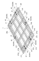
(第1の実施形態)図1及び図2を参照して、本発明の第1の実施形態である、パレットについて説明する。図1は本実施形態のパレットの外観を示す図である。図1に示すように、本実施形態のパレット1は、載置部20と、レール30と、ストッパ40とを備える。以下、各構成について詳細に説明する。
(First Embodiment) A pallet according to a first embodiment of the present invention will be described with reference to FIGS. FIG. 1 is a view showing the appearance of the pallet of this embodiment. As shown in FIG. 1, the pallet 1 of the present embodiment includes a
載置部20は、桟部21と外枠部22とを備えている。桟部21は、それぞれが平行に並んだ4本の横桟部211、212、213、214と、これら横桟部211、212、213、214に直交し、それぞれが平行に並んだ4本の縦桟部215、216、217、218とを備え、格子状を形成している。また、縦桟部215、216、217、218は、それぞれ分割されて横桟部211、212、213、214の側面に連結されており、横桟部211、212、213、214の上面と、縦桟部215、216、217、218の上面とは、ほぼ同一平面になるように構成されている。縦桟部215を例にすると、縦桟部215は、縦桟部材215a、215b、215c、215d、215eの5部材に分割されている。そして、縦桟部材215aはその一の端部が横桟部211の一の側面(外側の側面)に連結される。また、縦桟部材215bは横桟部211の他の側面から横桟部212の一の側面に渡り連結され、縦桟部材215cは横桟部212の他の側面から横桟部213の一の側面に渡りに連結され、縦桟部材215dは横桟部213の他の側面から横桟部214の一の側面に渡りに連結される。更に、縦桟部材215eはその一の端部が横桟部214の他の側面に連結される。
The
外枠部22は、桟部21を取り囲むように設けられている。外枠部22は、横枠部221、222と、横枠部221、222よりも短い縦枠部223、224とが長方形の4辺を構成するように、それぞれの両端部で連結されている。そして、格子状の桟部21の端部と外枠部22の内側面とが連結されている。
The
なお、部材の連結は、例えば溶接等により行われる。また、桟部21及び外枠部22は断面矩形状の金属角材からなる。
In addition, connection of a member is performed by welding etc., for example. Moreover, the
本実施形態においては、載置部20は桟部21を外枠部22で囲うような構成となっているが、板状の被載置物を支えるのは桟部21の上面の一部であるので、載置部20は、後述する板状の被載置物を載置する載置領域20aを確保できれば格子状の桟部21のみで外枠部22を除いた構成としても良い。
In the present embodiment, the
また、載置部20は、板状の被運搬物を載置する載置領域20aを形成する。載置領域20a(図1の中で、破線で取り囲まれ、破線でハッチングされた矩形状の領域)は、板状の被運搬物が載置部20に載置され得る領域であって、被運搬物の大きさや形状により変動する。具体的には、載置領域20aは、被運搬物をその側面から保持するストッパが取り囲んだ矩形状の領域であり、ストッパの可動範囲において変動する。
Moreover, the mounting
また、レール30は、矩形状の載置領域20aを含む面に沿うと共に、矩形状の載置領域20aの内側から外側に向かう方向に沿って配置される。具体的には、レール301、302は、縦桟部215から縦枠部223に渡り設けられ、レール303、304は、縦桟部218から縦枠部224に渡り設けられる。また、レール305は、横桟部211から横枠部221に渡り設けられ、レール306は、横桟部214から横枠部222に渡り設けられる。そして、それぞれのレール30上には保持部41を備えたストッパ40が設けられる。
In addition, the
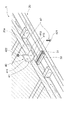
図2に本発明に係るレール30及びストッパ40の図を示す。レール30は、断面矩形状の金属角材の一面の中央長手方向にスリット31を有し、スリット31は載置領域20aを含む面に沿って設けられる。
FIG. 2 shows a view of the
レール30上には、レール30に沿って摺動し、レール30上の任意の位置において固定可能なようにストッパ40が設けられる。
A
ストッパ40は、被運搬物を保持するための保持部41と、保持部41をレール30に固定するための固定部42とを備える。保持部41は断面L字状の部材で被運搬物の側面に当接する当接部411とレール30のスリット31が設けられた面に対して摺動する摺動部412とを備え、摺動部412には固定部42を挿通するための貫通孔413を備える。なお、保持部41の形状はレール30に設置された場合に、載置領域20aを含む面から当該面と交わる方向に延びる形状であれば断面L字状に限らない。
The
固定部42は、ボルト421とナット422とを備える。ボルト421とナット422は、固定部42をレール30に沿って摺動させると共に、固定部42をレール30に固定させる役割を持つ。すなわち、ボルト421の頭部をレール30内部に遊嵌させると共に、ボルト421の胴部をレール30のスリット31から上方に突出させ、突出したボルト421の胴部を保持部41の貫通孔413に挿通させ、ボルト421の軸部にナット422を取り付けることにより、保持部41はレール30から離れることなくレール30に沿って摺動させることができる。また、ナット422を締め付けることにより、保持部41をレール30に固定することができる。
The fixing
次に、図3にパレット1に板状の被運搬物(鋼板)を載置した状態を示す。板状の被運搬物Aを載置部20の載置領域(図中被載置部Aの裏面に沿った領域)に置き、板状の被運搬物Aを取り囲むように設けたストッパ40を被運搬物Aの側面に当接するように摺動させる。その後、ストッパ40の固定部42のナット422を締め付けることによりストッパ40がレール30に固定され、板状の被運搬物Aがパレット1に載置される。なお、ストッパの保持部は、載置領域を含む面から当該面と交わる方向に延びているので、更に同様の形状の板状の被運搬物を重ねて載置することもできる。
Next, FIG. 3 shows a state where a plate-shaped object (steel plate) is placed on the pallet 1. A plate-like object A is placed on the placement area of the placement part 20 (an area along the back surface of the placement part A in the figure), and a
なお、本実施形態において、桟部21は、縦桟部と横桟部とがそれぞれ4本ずつで構成されているが、少なくとも2本ずつで構成されていれば良い。縦桟部、横桟部2本ずつ備えていれば格子状を形成することができ、板状の被運搬物を安定して載置させることができる。また、本実施形態は、ストッパ40を各縦枠部に二つずつ、各横枠部に一つずつ設けているが、被運搬物が運搬中にズレない程度におさえることができれば良く、少なくとも四方からそれぞれ一つずつのストッパを備えていれば良い。
In this embodiment, the
以上のように、本実施形態によれば、載置領域20aの内側から外側に向かう方向に沿って配置されるレール30に沿って摺動するストッパ40を備えているので、板状の被運搬物の形状や大きさに応じてストッパ40の位置を調整することができる。また、ストッパ40は、載置領域20aを含む面から当該面と交わる方向に延びる保持部41を有しているので、板状の被運搬物の側面を確実に保持することができる。従って、様々な形状や大きさの板状の被運搬物を簡便にパレットに固定することができる。
As described above, according to the present embodiment, since the
また、載置部20が、桟部21を有し、桟部21は横桟部211、212、213、214と縦桟部215、216、217、218が格子状になるように連結されているので、十分な強度を保つことができると共に、少ない部材で載置領域20aを形成することができる。従って、パレット1の強度を維持しつつ軽量化を図ることができる。
In addition, the mounting
(第2の実施形態)図4〜図6を参照して、本発明の第2の実施形態である、パレットについて説明する。本実施形態は第1の実施形態に係るパレットを複数積み重ねることができるように、第1の実施形態のパレットに所定の脚部と係合凹部を備えている。 (Second Embodiment) A pallet which is a second embodiment of the present invention will be described with reference to FIGS. In the present embodiment, the pallet of the first embodiment is provided with predetermined leg portions and engaging recesses so that a plurality of pallets according to the first embodiment can be stacked.
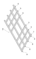
図4は本実施形態のパレットの外観を示す図である。図4に示すように、本実施形態のパレット10は、第1の実施形態のパレットに加えて、外枠部22(載置部20)の四隅から載置領域20aを含む面に交わりかつ載置領域20aを含む面に対して下方に延びた脚部50が設けられている。また、本実施形態では、横枠部221、222の下面の中央部から下方に伸びる脚部51が設けられている。脚部50、51は断面矩形状の金属角材からなる。
FIG. 4 is a view showing the appearance of the pallet of this embodiment. As shown in FIG. 4, in addition to the pallet of the first embodiment, the
また、載置領域20aを含む面を基準として、四隅に設けられた脚部50に対しそれぞれの反対側(外枠部22の四隅上面)に、載置領域20aを含む面に交わりかつ載置領域20aを含む面に対して上方に開口した係合凹部60が設けられている。また、係合凹部60は、載置領域20aを含む面から当該面に対して上方に突出して配置されている。
Further, with respect to the surface including the mounting
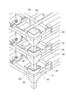
図5は本実施形態のパレットの係合凹部を示す図である。図5に示すように、係合凹部60は、他のパレットの脚部50を載せるための角部が面取りされた矩形状の内部底面61を備える。また、係合凹部60は、開口方向に向かって外側に傾斜した側壁部62を備え、内部底面61よりも大きな矩形状の開口端部63を備えている。側壁部62は、他のパレットの脚部が係合する際にその脚部をガイドするものである。また、他のパレットを重ねた後においては、脚部が載置された状態から動くことを防止する役割もある。なお、本実施形態においては、パレットの脚部50が断面矩形状であるために、断面矩形状の内部底面61及び開口端部63をこれに準じた形状としたが、パレットの脚部の断面形状に応じて適宜変更しても良い。例えば、パレットの脚部が断面円形状であれば、断面円形状の内部底面及び開口端部としても良い。
FIG. 5 is a view showing the engaging recess of the pallet of this embodiment. As shown in FIG. 5, the
図6は本実施形態のパレットについて複数積み重ねた状態を示す側面図である。図6に示すように、パレット10の四隅に設けられた脚部50の先端部が他のパレットの四隅に設けられた係合凹部60に係合されることにより、同一構成の別のパレットを複数積み重ねることができる。
FIG. 6 is a side view showing a state in which a plurality of pallets according to this embodiment are stacked. As shown in FIG. 6, the distal end portions of the
なお、本実施形態の他、脚部50は載置領域20aを含む面に交わりかつ載置領域20aに対して上方に延びるように設け、係合凹部60は載置領域20aを含む面を基準として、四隅に設けられた脚部50に対しそれぞれの反対側(外枠部22の四隅下面)に設けても良い。
In addition to this embodiment, the
また、図4に示すように、パレット10は、更に、横枠部221、222のそれぞれの下面にU字状のフォークガイド70を備えても良く、横枠部221、222の外側面の両端部付近にフック80を備えても良い。
Further, as shown in FIG. 4, the
以上のように、本実施形態によれば、載置領域20aを含む面と交わる方向に沿った線上脚部50と係合凹部60とが配置されているので、同一形状のパレットを重ねた場合、一のパレットの脚部の先端部と、他のパレットの係合凹部との位置が一致することになる。従って、同一形状の複数のパレットを確実に積み重ねることができる。
As described above, according to the present embodiment, the
また、本実施形態によれば、係合凹部60が、載置領域20aを含む面に対して突出しているので、係合凹部60が配置された部分以外に載置領域が形成されることになる。従って、同一形状のパレットを複数重ねた場合であっても、他のパレットの脚部によって被運搬物を傷つけることなく被運搬物の品質を保つことができる。
Moreover, according to this embodiment, since the engaging recessed
また、係合凹部60は開口方向に向かって外側に傾斜した側壁部62を備えているので、他のパレットの脚部50を係合する際に及び載置後において位置ズレを防止することができる。
In addition, since the engaging
また、脚部50を設けているので、フォークリフトのフォークをパレットの下部に入れることができる。また、横枠部221、222のそれぞれの下面にU字状のフォークガイド70を設けているので確実にフォークをパレット下部に導入することができる。
Moreover, since the
1、10…パレット、20…載置部、21…桟部、30…レール、40…ストッパ、50…脚部、60…係合凹部
DESCRIPTION OF
Claims (4)
前記載置領域を含む面に沿うと共に、前記載置領域の内側から外側に向かう方向に沿って配置されるレールと、
前記レールに沿って摺動し、前記レール上の任意の位置において固定可能なように構成されると共に、前記載置領域を含む面から当該面と交わる方向に延びる保持部を有するストッパと、を備える板運搬用パレット。 A plate transporting pallet including a mounting portion that forms a mounting region for mounting a plate-shaped object to be transported,
A rail disposed along the direction including the placement area, and along the direction from the inside to the outside of the placement area,
A stopper that slides along the rail and is configured to be fixed at an arbitrary position on the rail, and has a holding portion that extends in a direction intersecting with the surface from the surface including the placement region. Pallet for board transportation provided.
The plate engaging pallet according to claim 3, wherein the engaging recess is disposed so as to protrude from a surface including the placement area.
Priority Applications (1)
| Application Number | Priority Date | Filing Date | Title |
|---|---|---|---|
| JP2006139132A JP2007308169A (en) | 2006-05-18 | 2006-05-18 | Pallet for transporting plate |
Applications Claiming Priority (1)
| Application Number | Priority Date | Filing Date | Title |
|---|---|---|---|
| JP2006139132A JP2007308169A (en) | 2006-05-18 | 2006-05-18 | Pallet for transporting plate |
Publications (1)
| Publication Number | Publication Date |
|---|---|
| JP2007308169A true JP2007308169A (en) | 2007-11-29 |
Family
ID=38841398
Family Applications (1)
| Application Number | Title | Priority Date | Filing Date |
|---|---|---|---|
| JP2006139132A Pending JP2007308169A (en) | 2006-05-18 | 2006-05-18 | Pallet for transporting plate |
Country Status (1)
| Country | Link |
|---|---|
| JP (1) | JP2007308169A (en) |
Cited By (4)
| Publication number | Priority date | Publication date | Assignee | Title |
|---|---|---|---|---|
| JP2011148552A (en) * | 2009-12-25 | 2011-08-04 | Asahi Glass Co Ltd | Storage container for plate-shaped body |
| JP2012240690A (en) * | 2011-05-17 | 2012-12-10 | Sanko Co Ltd | Pallet |
| CN103029917A (en) * | 2008-04-16 | 2013-04-10 | 康宁股份有限公司 | Packing of glass sheets |
| JP2019011082A (en) * | 2017-06-29 | 2019-01-24 | 大和ハウス工業株式会社 | Storage rack |
-
2006
- 2006-05-18 JP JP2006139132A patent/JP2007308169A/en active Pending
Cited By (4)
| Publication number | Priority date | Publication date | Assignee | Title |
|---|---|---|---|---|
| CN103029917A (en) * | 2008-04-16 | 2013-04-10 | 康宁股份有限公司 | Packing of glass sheets |
| JP2011148552A (en) * | 2009-12-25 | 2011-08-04 | Asahi Glass Co Ltd | Storage container for plate-shaped body |
| JP2012240690A (en) * | 2011-05-17 | 2012-12-10 | Sanko Co Ltd | Pallet |
| JP2019011082A (en) * | 2017-06-29 | 2019-01-24 | 大和ハウス工業株式会社 | Storage rack |
Similar Documents
| Publication | Publication Date | Title |
|---|---|---|
| JP2007308169A (en) | Pallet for transporting plate | |
| JP5061321B2 (en) | Transport pallet | |
| JP3165973U (en) | Plate-shaped body storage container | |
| JP2010247726A (en) | Carrying device | |
| JP2008100726A (en) | Pallet for forklift | |
| JP2006182470A (en) | Lateral slip prevention device of pallet of loading shelf | |
| JPWO2007088675A1 (en) | Plate carrier | |
| JP3141972U (en) | Rack fitting | |
| KR20170000772U (en) | Trolley | |
| JP6179749B2 (en) | Pallet drop prevention device used for existing racks in a three-dimensional automatic warehouse | |
| JP2007039136A (en) | Pallet cradle | |
| JP2007106442A (en) | Pallet | |
| JP6594654B2 (en) | palette | |
| JP6535155B2 (en) | Shipping container | |
| JP6704202B1 (en) | Workpiece storage device and workpiece loading method | |
| JP2007045470A (en) | Pallet and pallet pole | |
| JP6603735B2 (en) | Rack and storage system with pallet function | |
| JP6031296B2 (en) | Pallet changer and pallet changer storage method | |
| JP2013216489A (en) | Fall prevention member and storage shelf | |
| JP2016047726A (en) | container | |
| KR200440984Y1 (en) | A steel box | |
| JP2007204126A (en) | Pallet | |
| JP3209660U (en) | truck | |
| KR20120003690U (en) | Pallet assembly | |
| JP2001048169A (en) | Storage container |