JP2007304814A - Print system, process device, job management device, control method for them, and program - Google Patents
Print system, process device, job management device, control method for them, and program Download PDFInfo
- Publication number
- JP2007304814A JP2007304814A JP2006131811A JP2006131811A JP2007304814A JP 2007304814 A JP2007304814 A JP 2007304814A JP 2006131811 A JP2006131811 A JP 2006131811A JP 2006131811 A JP2006131811 A JP 2006131811A JP 2007304814 A JP2007304814 A JP 2007304814A
- Authority
- JP
- Japan
- Prior art keywords
- job
- processing
- notification
- combined
- management information
- Prior art date
- Legal status (The legal status is an assumption and is not a legal conclusion. Google has not performed a legal analysis and makes no representation as to the accuracy of the status listed.)
- Granted
Links
Images


Classifications
-
- G—PHYSICS
- G06—COMPUTING; CALCULATING OR COUNTING
- G06F—ELECTRIC DIGITAL DATA PROCESSING
- G06F3/00—Input arrangements for transferring data to be processed into a form capable of being handled by the computer; Output arrangements for transferring data from processing unit to output unit, e.g. interface arrangements
- G06F3/12—Digital output to print unit, e.g. line printer, chain printer
- G06F3/1201—Dedicated interfaces to print systems
- G06F3/1278—Dedicated interfaces to print systems specifically adapted to adopt a particular infrastructure
- G06F3/1285—Remote printer device, e.g. being remote from client or server
- G06F3/1288—Remote printer device, e.g. being remote from client or server in client-server-printer device configuration
-
- G—PHYSICS
- G06—COMPUTING; CALCULATING OR COUNTING
- G06F—ELECTRIC DIGITAL DATA PROCESSING
- G06F3/00—Input arrangements for transferring data to be processed into a form capable of being handled by the computer; Output arrangements for transferring data from processing unit to output unit, e.g. interface arrangements
- G06F3/12—Digital output to print unit, e.g. line printer, chain printer
- G06F3/1201—Dedicated interfaces to print systems
- G06F3/1202—Dedicated interfaces to print systems specifically adapted to achieve a particular effect
- G06F3/1203—Improving or facilitating administration, e.g. print management
- G06F3/1207—Improving or facilitating administration, e.g. print management resulting in the user being informed about print result after a job submission
-
- G—PHYSICS
- G06—COMPUTING; CALCULATING OR COUNTING
- G06F—ELECTRIC DIGITAL DATA PROCESSING
- G06F3/00—Input arrangements for transferring data to be processed into a form capable of being handled by the computer; Output arrangements for transferring data from processing unit to output unit, e.g. interface arrangements
- G06F3/12—Digital output to print unit, e.g. line printer, chain printer
- G06F3/1201—Dedicated interfaces to print systems
- G06F3/1223—Dedicated interfaces to print systems specifically adapted to use a particular technique
- G06F3/1237—Print job management
- G06F3/1259—Print job monitoring, e.g. job status
-
- G—PHYSICS
- G06—COMPUTING; CALCULATING OR COUNTING
- G06F—ELECTRIC DIGITAL DATA PROCESSING
- G06F3/00—Input arrangements for transferring data to be processed into a form capable of being handled by the computer; Output arrangements for transferring data from processing unit to output unit, e.g. interface arrangements
- G06F3/12—Digital output to print unit, e.g. line printer, chain printer
- G06F3/1201—Dedicated interfaces to print systems
- G06F3/1223—Dedicated interfaces to print systems specifically adapted to use a particular technique
- G06F3/1237—Print job management
- G06F3/126—Job scheduling, e.g. queuing, determine appropriate device
- G06F3/1262—Job scheduling, e.g. queuing, determine appropriate device by grouping or ganging jobs
-
- G—PHYSICS
- G06—COMPUTING; CALCULATING OR COUNTING
- G06F—ELECTRIC DIGITAL DATA PROCESSING
- G06F3/00—Input arrangements for transferring data to be processed into a form capable of being handled by the computer; Output arrangements for transferring data from processing unit to output unit, e.g. interface arrangements
- G06F3/12—Digital output to print unit, e.g. line printer, chain printer
- G06F3/1201—Dedicated interfaces to print systems
- G06F3/1223—Dedicated interfaces to print systems specifically adapted to use a particular technique
- G06F3/1275—Print workflow management, e.g. defining or changing a workflow, cross publishing
-
- G—PHYSICS
- G06—COMPUTING; CALCULATING OR COUNTING
- G06F—ELECTRIC DIGITAL DATA PROCESSING
- G06F2206/00—Indexing scheme related to dedicated interfaces for computers
- G06F2206/15—Indexing scheme related to printer interfaces for computers, indexing schema related to group G06F3/12
- G06F2206/1514—Sub-job
-
- G—PHYSICS
- G06—COMPUTING; CALCULATING OR COUNTING
- G06F—ELECTRIC DIGITAL DATA PROCESSING
- G06F3/00—Input arrangements for transferring data to be processed into a form capable of being handled by the computer; Output arrangements for transferring data from processing unit to output unit, e.g. interface arrangements
- G06F3/12—Digital output to print unit, e.g. line printer, chain printer
- G06F3/1201—Dedicated interfaces to print systems
- G06F3/1202—Dedicated interfaces to print systems specifically adapted to achieve a particular effect
- G06F3/1203—Improving or facilitating administration, e.g. print management
- G06F3/1208—Improving or facilitating administration, e.g. print management resulting in improved quality of the output result, e.g. print layout, colours, workflows, print preview
-
- G—PHYSICS
- G06—COMPUTING; CALCULATING OR COUNTING
- G06F—ELECTRIC DIGITAL DATA PROCESSING
- G06F3/00—Input arrangements for transferring data to be processed into a form capable of being handled by the computer; Output arrangements for transferring data from processing unit to output unit, e.g. interface arrangements
- G06F3/12—Digital output to print unit, e.g. line printer, chain printer
- G06F3/1201—Dedicated interfaces to print systems
- G06F3/1223—Dedicated interfaces to print systems specifically adapted to use a particular technique
- G06F3/1237—Print job management
- G06F3/1253—Configuration of print job parameters, e.g. using UI at the client
- G06F3/1256—User feedback, e.g. print preview, test print, proofing, pre-flight checks
-
- G—PHYSICS
- G06—COMPUTING; CALCULATING OR COUNTING
- G06F—ELECTRIC DIGITAL DATA PROCESSING
- G06F3/00—Input arrangements for transferring data to be processed into a form capable of being handled by the computer; Output arrangements for transferring data from processing unit to output unit, e.g. interface arrangements
- G06F3/12—Digital output to print unit, e.g. line printer, chain printer
- G06F3/1201—Dedicated interfaces to print systems
- G06F3/1278—Dedicated interfaces to print systems specifically adapted to adopt a particular infrastructure
- G06F3/1291—Pool of printer devices: self-managing printing devices in a network, e.g. without a server
Abstract
Description
本発明は、印刷から製本に至るまでの各工程の処理を実行する複数の工程装置を用いて、最終生成物を生成する印刷システム、工程装置、ジョブ管理装置及びそれらの制御方法、プログラムに関するものである。 The present invention relates to a printing system, a process apparatus, a job management apparatus, a control method thereof, and a program for generating a final product using a plurality of process apparatuses that execute processing of each process from printing to bookbinding. It is.
商業的印刷業界は、第三者(顧客、クライアント)から印刷物(雑誌、新聞、カタログ、広告、グラビア等)の作成依頼を受注し、該クライアントの所望の印刷物を作成し、それを該クライアントに納品することでクライアントから報酬を得る。この商業的印刷業界では、現在でも、オフセット製版印刷機等の大規模な印刷装置を用いているのが主流である。 The commercial printing industry receives an order to create a printed matter (magazine, newspaper, catalog, advertisement, gravure, etc.) from a third party (customer, client), creates the desired printed matter for the client, and sends it to the client. Receive rewards from clients for delivery. In the commercial printing industry, a large-scale printing apparatus such as an offset plate-making printing machine is still used today.
この商業的印刷業界では、様々な工程を踏んで作業が進められる。この工程には、例えば、入稿、デザインやレイアウト、カンプ(プリンタ出力によるプレゼンテーション)、校正(レイアウト修正や色修正)、校正刷り(プルーフプリント)、版下作成、印刷、後処理加工、発送等がある。 In the commercial printing industry, work proceeds through various processes. This process includes, for example, submission, design and layout, comp (presentation by printer output), proofreading (layout correction and color correction), proof printing (proof print), composition creation, printing, post-processing, shipping, etc. There is.
一方で、最近、電子写真方式の印刷装置やインクジェット方式の印刷装置の高速化、高画質化に伴い、上記のような印刷業界に対抗して、プリント・オン・デマンドという業態が出現しつつある。以下、プリント・オン・デマンド(Print On Demand)は、PODと略記する。 On the other hand, with the recent increase in the speed and image quality of electrophotographic printing devices and inkjet printing devices, a business format called print-on-demand has emerged against the printing industry as described above. . Hereinafter, Print On Demand is abbreviated as POD.
PODでは、印刷装置で扱うジョブを、より比較的小ロットのジョブに分けることで、大掛かりな装置、システムを用いずに、短納期で印刷処理を取り扱うことを目指している。特に、このPODでは、上記のような大規模な印刷機、印刷手法に代えて、例えば、デジタル複写機やデジタル複合機等のデジタル画像形成装置を最大限に活用して、電子データを用いたデジタルプリントを実現している。そして、このPODによる業態のPOD市場が展開されつつある。このようなPOD市場では、従来の印刷業界に比べてデジタル化が融合し、コンピュータを利用した管理、制御が浸透してきている。 POD aims to handle printing processing with a short delivery time without using a large-scale device or system by dividing jobs handled by the printing device into jobs of relatively small lots. In particular, in this POD, instead of the large-scale printing machine and printing method as described above, for example, digital image forming apparatuses such as a digital copying machine and a digital multifunction machine are used to the maximum, and electronic data is used. Digital printing is realized. And the POD market of the business type by this POD is being developed. In such a POD market, digitization is more integrated than in the conventional printing industry, and management and control using a computer has been permeating.
このようなPODシステムでは、複数の印刷ジョブを1つの印刷ジョブ(Gang−Job(ギャングジョブ))に結合して印刷し、得られる印刷物を断裁して、各印刷ジョブに対応する印刷物を得ることが行われている。 In such a POD system, a plurality of print jobs are combined into one print job (Gang-Job (gang job)) and printed, and the obtained printed matter is cut to obtain a printed matter corresponding to each print job. Has been done.
また、画像形成装置による印刷工程が終了した場合に、ジョブを投入した上位装置であるクライアントコンピュータにジョブの終了通知を行う技術がある(例えば、特許文献1)。 Also, there is a technique for notifying the end of a job to a client computer that is a host apparatus that has input the job when the printing process by the image forming apparatus is completed (for example, Patent Document 1).
また、従来の画像形成処理装置により出力された原稿用紙を、フィニッシング装置で製本処理(ステイプル、穴あけ、中綴じ製本、くるみ製本等)を行うことは周知となっている。
しかしながら、特許文献1に記載されている終了通知に関する上記の従来技術では、処理中のジョブが終了することに応じてジョブの終了通知を行っている。
However, in the above-described related art relating to the end notification described in
ここで、ギャングジョブに含まれる複数の印刷ジョブの生成元が、例えば、ユーザA〜Cである場合を想定する。この場合、従来のジョブ終了通知の技術を適用すると、PODシステムにおいて、ギャングジョブを処理する場合には、ギャングジョブの全処理が完全に終了した後に、ユーザA〜Cが操作するクライアントに対して、その終了の通知がなされる構成となっている。 Here, it is assumed that the generation sources of a plurality of print jobs included in the gang job are, for example, users A to C. In this case, when the conventional job end notification technology is applied, in the case of processing a gang job in the POD system, after all processing of the gang job is completely ended, the client operated by the users A to C The end notification is made.
つまり、PODシステムのように、複数のジョブが結合されたギャングジョブを処理する場合は、ギャングジョブの一部として第一番目にサブミットされたジョブのユーザは、ギャングジョブ全体の処理が終了しないと、そのユーザ分のジョブの終了通知を受け取れない。また、同時に、第一番目にサブミットされたジョブのユーザは、ギャングジョブ全体の処理が終了しないと、そのジョブに対する成果物(印刷物)を受け取れない。 That is, when processing a gang job in which a plurality of jobs are combined as in the POD system, the user of the job submitted first as a part of the gang job must complete the processing of the entire gang job. Cannot receive job completion notification for that user. At the same time, the user of the first submitted job cannot receive a product (printed material) for the job unless the processing of the entire gang job is completed.
これは、ギャングジョブが複数のジョブを1つのジョブとして扱うため、そのギャングジョブ中の最初のジョブ分の印刷が終了しているにも関わらず、そのギャングジョブ中の最後のジョブ分の印刷が完了しない限り、印刷終了にならないからである。そのため、ギャングジョブにおいて、最初のジョブ自体の印刷が完了している場合でも、その完了したことを、ギャングジョブ全体が完全に終了することに先立って認識することができない。 This is because a gang job handles a plurality of jobs as one job, and printing for the last job in the gang job is completed even though printing for the first job in the gang job has been completed. This is because the printing will not end unless it is completed. Therefore, even when printing of the first job itself is completed in the gang job, the completion cannot be recognized before the entire gang job is completed.
本発明は上記の課題に鑑みてなされたものであり、複数の工程装置を介して印刷物を生成する印刷システムにおける処理効率を向上させることができる印刷システム、工程装置、ジョブ管理装置及びそれらの制御方法、プログラムを提供することを目的とする。 The present invention has been made in view of the above problems, and is capable of improving processing efficiency in a printing system that generates printed matter via a plurality of process devices, a process device, a job management device, and control thereof. The object is to provide a method and a program.
上記の目的を達成するための本発明による印刷システムは以下の構成を備える。即ち、
ジョブ管理装置と、最終生成物を生成すべく印刷から製本に至るまでの各工程の処理を実行する複数の工程装置とを含む印刷システムであって、
前記ジョブ管理装置は、
複数のジョブを結合した結合ジョブを生成するジョブ結合手段を備え、
前記複数の工程装置の少なくとも1つは、
前記ジョブ管理装置から、複数のジョブを結合した結合ジョブを受信する受信手段と、
前記受信手段で受信した結合ジョブの処理内容を示すジョブ管理情報に基づいて、前記結合ジョブを処理する処理手段と、
前記結合ジョブを構成する複数のジョブそれぞれについての前記処理手段による処理の終了通知を、指定された通知先へ送信する通知手段と
を備える。
In order to achieve the above object, a printing system according to the present invention comprises the following arrangement. That is,
A printing system including a job management device and a plurality of process devices that execute processing of each process from printing to bookbinding to generate a final product,
The job management device includes:
A job combining means for generating a combined job by combining a plurality of jobs;
At least one of the plurality of process devices includes:
Receiving means for receiving a combined job obtained by combining a plurality of jobs from the job management device;
Processing means for processing the combined job based on job management information indicating processing contents of the combined job received by the receiving means;
Notification means for transmitting a processing end notification by the processing means for each of a plurality of jobs constituting the combined job to a designated notification destination.
また、好ましくは、前記複数の工程装置の少なくとも1つは、更に、
自身の下流にある工程装置に、前記結合ジョブを構成する複数のジョブそれぞれについての処理の終了通知を、指定された通知先へ送信させるための通知指示情報を生成する生成手段と、
前記生成手段で生成した通知指示情報を含む前記ジョブ管理情報を前記結合ジョブと共に、自身の下流にある工程装置へ送信するジョブ送信手段と
を備える。
Preferably, at least one of the plurality of process devices further includes:
Generating means for generating notification instruction information for causing a process device downstream of the processing apparatus to transmit a processing end notification for each of a plurality of jobs constituting the combined job to a designated notification destination;
A job transmission unit configured to transmit the job management information including the notification instruction information generated by the generation unit to the process apparatus downstream of the job management information together with the combined job.
また、好ましくは、前記通知手段は、前記結合ジョブのジョブ管理情報に含まれる通知指示情報に基づいて、該結合ジョブを構成する複数のジョブそれぞれについての前記処理手段による処理が終了する毎にその終了通知を、指定された通知先へ送信する。 Preferably, the notifying unit performs the processing every time processing by the processing unit for each of a plurality of jobs constituting the combined job is completed based on notification instruction information included in job management information of the combined job. An end notification is sent to the specified notification destination.
また、好ましくは、前記ジョブ管理装置は、
前記複数の工程装置の内の指定された工程装置における前記結合ジョブを構成する複数のジョブそれぞれについての処理の終了通知を、指定された通知先へ送信させるための通知指示情報を生成する通知指示情報を含む、結合ジョブの処理内容を示すジョブ管理情報を生成するジョブ管理情報生成手段と、
前記ジョブ管理情報を含む結合ジョブを、前記複数の工程装置の内の指定された工程装置へ出力する出力手段と
を備える。
Preferably, the job management device includes:
Notification instruction for generating notification instruction information for transmitting a process end notification for each of a plurality of jobs constituting the combined job in a specified process device among the plurality of process devices to a specified notification destination Job management information generating means for generating job management information indicating the processing content of the combined job including information;
Output means for outputting a combined job including the job management information to a designated process device among the plurality of process devices.
上記の目的を達成するための本発明による工程装置は以下の構成を備える。即ち、
印刷から製本に至るまでの各工程の処理を実行する複数の工程装置を用いて、最終生成物を生成する印刷システムにおける工程装置であって
自身の上流にある工程装置から、複数のジョブを結合した結合ジョブを受信する受信手段と、
前記受信手段で受信した結合ジョブの処理内容を示すジョブ管理情報に基づいて、前記結合ジョブを処理する処理手段と、
前記結合ジョブを構成する複数のジョブそれぞれについての前記処理手段による処理の終了通知を、指定された通知先へ送信する通知手段と
を備える。
In order to achieve the above object, a process apparatus according to the present invention comprises the following arrangement. That is,
Combine multiple jobs from the process equipment in the printing system that produces the final product using the process equipment that executes each process from printing to bookbinding, and that is upstream of itself. Receiving means for receiving the combined job,
Processing means for processing the combined job based on job management information indicating processing contents of the combined job received by the receiving means;
Notification means for transmitting a processing end notification by the processing means for each of a plurality of jobs constituting the combined job to a designated notification destination.
上記の目的を達成するための本発明によるジョブ管理装置は以下の構成を備える。即ち、
印刷から製本に至るまでの各工程の処理を実行する複数の工程装置を用いて、最終生成物を生成する印刷システムにおけるジョブ及びその処理内容を示すジョブ管理情報を生成するジョブ管理装置であって、
複数のジョブを結合した結合ジョブを生成する結合ジョブ生成手段と、
前記複数の工程装置の内の指定された工程装置における前記結合ジョブを構成する複数のジョブそれぞれについての処理の終了通知を、指定された通知先へ送信させるための通知指示情報を生成する通知指示情報を含む、結合ジョブの処理内容を示すジョブ管理情報を生成するジョブ管理情報生成手段と、
前記ジョブ管理情報を含む結合ジョブを、前記複数の工程装置の内の指定された工程装置へ出力する出力手段と
を備える。
In order to achieve the above object, a job management apparatus according to the present invention comprises the following arrangement. That is,
A job management apparatus that generates a job management information indicating a job and processing contents in a printing system that generates a final product by using a plurality of process apparatuses that execute processes of each process from printing to bookbinding. ,
A combined job generation means for generating a combined job by combining a plurality of jobs;
Notification instruction for generating notification instruction information for transmitting a process end notification for each of a plurality of jobs constituting the combined job in a specified process device of the plurality of process devices to a specified notification destination Job management information generating means for generating job management information indicating the processing content of the combined job including information;
Output means for outputting a combined job including the job management information to a designated process device among the plurality of process devices.
上記の目的を達成するための本発明による工程装置の制御方法は以下の構成を備える。即ち、
印刷から製本に至るまでの各工程の処理を実行する複数の工程装置を用いて、最終生成物を生成する印刷システムにおける工程装置の制御方法であって
自身の上流にある工程装置から、複数のジョブを結合した結合ジョブを受信する受信工程と、
前記受信工程で受信した結合ジョブの処理内容を示すジョブ管理情報に基づいて、前記結合ジョブを処理する処理工程と、
前記結合ジョブを構成する複数のジョブそれぞれについての前記処理工程による処理の終了通知を、指定された通知先へ送信する通知工程と
を備える。
In order to achieve the above object, a method for controlling a process apparatus according to the present invention comprises the following arrangement. That is,
A method of controlling a process device in a printing system that generates a final product using a plurality of process devices that execute processing of each process from printing to bookbinding. A receiving process for receiving a combined job obtained by combining jobs;
A processing step of processing the combined job based on job management information indicating processing contents of the combined job received in the receiving step;
A notification step of transmitting, to a designated notification destination, a notification of completion of processing by the processing step for each of a plurality of jobs constituting the combined job.
上記の目的を達成するための本発明によるジョブ管理装置の制御方法は以下の構成を備える。即ち、
印刷から製本に至るまでの各工程の処理を実行する複数の工程装置を用いて、最終生成物を生成する印刷システムにおけるジョブ及びその処理内容を示すジョブ管理情報を生成するジョブ管理装置の制御方法であって、
複数のジョブを結合した結合ジョブを生成する結合ジョブ生成工程と、
前記複数の工程装置の内の指定された工程装置における前記結合ジョブを構成する複数のジョブそれぞれについての処理の終了通知を、指定された通知先へ送信させるための通知指示情報を生成する通知指示情報を含む、結合ジョブの処理内容を示すジョブ管理情報を生成するジョブ管理情報生成工程と、
前記ジョブ管理情報を含む結合ジョブを、前記複数の工程装置の内の指定された工程装置へ出力する出力工程と
を備えることを特徴とするジョブ管理装置の制御方法。
In order to achieve the above object, a method for controlling a job management apparatus according to the present invention comprises the following arrangement. That is,
Control method of job management apparatus for generating job management information indicating job and processing contents in printing system for generating final product using a plurality of process apparatuses for executing processing of each process from printing to bookbinding Because
A combined job generation process for generating a combined job by combining a plurality of jobs;
Notification instruction for generating notification instruction information for transmitting a process end notification for each of a plurality of jobs constituting the combined job in a specified process device among the plurality of process devices to a specified notification destination A job management information generation step for generating job management information indicating the processing content of the combined job, including information;
An output process for outputting a combined job including the job management information to a specified process apparatus among the plurality of process apparatuses.
上記の目的を達成するための本発明によるプログラムは以下の構成を備える。即ち、
印刷から製本に至るまでの各工程の処理を実行する複数の工程装置を用いて、最終生成物を生成する印刷システムにおける工程装置の制御をコンピュータに実行させるためのプログラムであって
自身の上流にある工程装置から、複数のジョブを結合した結合ジョブを受信する受信工程と、
前記受信工程で受信した結合ジョブの処理内容を示すジョブ管理情報に基づいて、前記結合ジョブを処理する処理工程と、
前記結合ジョブを構成する複数のジョブそれぞれについての前記処理工程による処理の終了通知を、指定された通知先へ送信する通知工程と
をコンピュータに実行させる。
In order to achieve the above object, a program according to the present invention comprises the following arrangement. That is,
A program for causing a computer to execute control of a process device in a printing system that generates a final product using a plurality of process devices that execute processing of each process from printing to bookbinding. A receiving process for receiving a combined job obtained by combining a plurality of jobs from a certain process device;
A processing step of processing the combined job based on job management information indicating processing contents of the combined job received in the receiving step;
Causing the computer to execute a notification step of transmitting, to a designated notification destination, an end notification of the processing by the processing step for each of a plurality of jobs constituting the combined job.
上記の目的を達成するための本発明によるプログラムは以下の構成を備える。即ち、
印刷から製本に至るまでの各工程の処理を実行する複数の工程装置を用いて、最終生成物を生成する印刷システムにおけるジョブ及びその処理内容を示すジョブ管理情報を生成するジョブ管理装置の制御をコンピュータに実行させるためのプログラムであって、
複数のジョブを結合した結合ジョブを生成する結合ジョブ生成工程と、
前記複数の工程装置の内の指定された工程装置における前記結合ジョブを構成する複数のジョブそれぞれについての処理の終了通知を、指定された通知先へ送信させるための通知指示情報を生成する通知指示情報を含む、結合ジョブの処理内容を示すジョブ管理情報を生成するジョブ管理情報生成工程と、
前記ジョブ管理情報を含む結合ジョブを、前記複数の工程装置の内の指定された工程装置へ出力する出力工程と
をコンピュータに実行させる。
In order to achieve the above object, a program according to the present invention comprises the following arrangement. That is,
Using a plurality of process devices that execute processing of each process from printing to bookbinding, control of a job management apparatus that generates job management information indicating a job and processing contents in a printing system that generates a final product is performed. A program for causing a computer to execute,
A combined job generation process for generating a combined job by combining a plurality of jobs;
Notification instruction for generating notification instruction information for transmitting a process end notification for each of a plurality of jobs constituting the combined job in a specified process device among the plurality of process devices to a specified notification destination A job management information generation step for generating job management information indicating the processing content of the combined job, including information;
Causing the computer to execute an output step of outputting the combined job including the job management information to a specified process device among the plurality of process devices.
本発明によれば、複数の工程装置を介して印刷物を生成する印刷システムにおける処理効率を向上させることができる印刷システム、工程装置、ジョブ管理装置及びそれらの制御方法、プログラムを提供できる。 ADVANTAGE OF THE INVENTION According to this invention, the printing system which can improve the processing efficiency in the printing system which produces | generates printed matter via several process apparatus, a process apparatus, a job management apparatus, those control methods, and a program can be provided.
以下、本発明の実施の形態について図面を用いて詳細に説明する。 Hereinafter, embodiments of the present invention will be described in detail with reference to the drawings.
本発明の実施形態を説明するのに先立って、まず、図1から図4を用いて、従来のPODシステムの構成の一例を説明する。これらの図面を用いて説明する内容は、一般的なPODシステムに関する説明であり、以下の実施形態で説明していない他の用途でも使用している場合がある。また、これらの図に関わる使用例の説明に関しては、実施形態で説明することとする。 Prior to describing the embodiment of the present invention, first, an example of the configuration of a conventional POD system will be described with reference to FIGS. 1 to 4. The content described with reference to these drawings is a description of a general POD system, and may be used for other purposes not described in the following embodiments. In addition, description of usage examples related to these drawings will be described in the embodiment.
図1は印刷システム全体の基本構成の一例を示すブロック図である。 FIG. 1 is a block diagram showing an example of the basic configuration of the entire printing system.
図1は、POD(Print On Demand)システムの一例であり、かつ本発明における一つの印刷システム基本構成の一例である。この印刷システムでは、印刷工程と各種印刷後工程を含む各種工程(ジョブ)の管理情報(ジョブ管理情報)であるJDFデータにより実現される印刷システムの一例を示している。 FIG. 1 is an example of a POD (Print On Demand) system, and an example of one basic printing system configuration in the present invention. This printing system shows an example of a printing system realized by JDF data that is management information (job management information) of various processes (jobs) including a printing process and various post-printing processes.
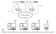
本ブロック図は、1つまたは複数のエンドユーザ環境1、2と、インターネットを介して接続されているPODサイト環境3から成っている。エンドユーザ環境1と2は、プリントの発注依頼を行う発注者が存在する。そして、それぞれのエンドユーザ環境(ここでは、エンドユーザ環境A及びエンドユーザ環境B)からそれぞれのクライアントPCを利用して、印刷ジョブの依頼を始めとして、ジョブのステータス確認等ができる。
The block diagram comprises one or more
一方、PODサイト環境3においては、通常は、工程管理部4、デジタルプリント部5から成り立っている。しかしながら、デジタルプリント部5に構成されるデジタル複写機やデジタル複合機等のデジタル画像形成装置に接続されているフィニッシング装置の機能や能力で不足する場合には、ポストプレス部6を更に追加することも可能である。更には、用途や目的に応じて、プリプレス部7を追加することも可能である。そして、これらの工程管理部4、デジタルプリント部5、ポストプレス部6、プリプレス部7は、ネットワーク8を介して相互に接続されている。
On the other hand, the
工程管理部4は、PODサイト環境における工程管理部4、デジタルプリント部5、ポストプレス部6の各工程に対して作業を指示し、コンピュータや各種デバイスにより構成される本システムのワークフローを一元管理する部分である。この工程管理部4は、エンドユーザ環境のクライアントPCからジョブを受信したり、保管したりする。更には、この工程管理部4は、エンドユーザ環境のクライアントPCからのジョブの指定に基づいて、各工程における作業をワークフローとして組み立てたり、各デバイスや各作業者における作業を効率よくスケジュールしたりする等の役割を果たす。
The
プリプレス部7は、工程管理部4より受信したプリプレスジョブの作業指示に基づいて、スキャナ/MFP等のスキャンデバイスによりエンドユーザから受け取った紙原稿をスキャンする。また、プリプレス部7は、スキャン画像ファイルとしてプリプレスサーバやクライアントPCに取り込む。これに加えて、プリプレス部7は、画像補正やファイルのマージやページの挿入/削除や各種ページレイアウト編集や面付け処理等の各種処理を実行する。また、プリプレス部7は、必要に応じて最終成果物のレイアウトや色味を確認するためのプルーフ出力を実行したりする等の役割を果たす。
The
ここで、MFPは、Multi Function Peripheral(マルチファンクション周辺機器)の略称である。 Here, MFP is an abbreviation for Multi Function Peripheral.
デジタルプリント部5は、工程管理部4あるいはプリプレス部7より受信した印刷ジョブの作業指示に従って、スキャン&プリントデバイスによりエンドユーザから受け取った紙原稿をコピーする。これに加えて、デジタルプリント部5は、クライアントPCからプリンタドライバやホットフォルダを経由して、受信したファイルをプリントデバイスにプリントアウトしたりする等の役割を果たす。ここで、受信するファイルとしては、エンドユーザ環境のクライアントPCから受信した文書/画像ファイル、スキャンデバイスから得られるスキャン画像ファイル、それらを編集した文書/画像ファイル等がある。また、スキャン&プリントデバイスには、白黒MFPやカラーMFP等がある。
The
ポストプレス部6は、工程管理部4、プリプレス部7あるいはデジタルプリント部5より受信したポストプレスジョブの作業指示に従って、紙折り機、中綴じ製本機、くるみ製本機、断裁機、封入機、帳合機等の後処理装置を制御する。これに加えて、ポストプレス部6は、デジタルプリント部5より出力された印刷物に対して、紙折り、中綴じ製本、くるみ製本、断裁、封入、帳合等の仕上げ処理を実行するという役割を果たす。
The
[工程管理部のシステム構成]
図2は工程管理部の構成の一例を示すブロック図である。
[System configuration of process management department]
FIG. 2 is a block diagram showing an example of the configuration of the process management unit.
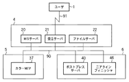
工程管理部4は、ネットワーク24に接続されたMIS(Management Information System)サーバ20、受注サーバ21、ファイルサーバ22、クライアントPC23等から構成されている。
The
ここで、MISサーバ20は、受注から納品までのシステム全体のワークフローを管理すると共に、様々な経営情報や販売情報を統括的に管理するシステムにおけるサーバである。
Here, the
受注サーバ21は、インターネットを利用して、エンドユーザ環境1や2のクライアントPCからジョブを受信するサーバである。受信したジョブは、ジョブのID番号で管理され、ID番号と管理上必要となる情報はMISサーバ20に伝えられ、MISサーバ20の指示に従って、画像データ等のそれ以外の情報と一緒に下流の工程に伝える役割を持っている。
The
ファイルサーバ22は、エンドユーザ環境1や2のクライアントPCからの同一原稿による再発注に備えて、クライアントPCから受信したジョブを保管するため文書管理サーバである。一般に、ファイルサーバ22には、画像データと前回出力の際のジョブの設定情報(ジョブチケット)を一緒に保存してある。
The
工程管理部4におけるこれらのMISサーバ20、受注サーバ21、ファイルサーバ22、クライアントPC23間でやり取りされる情報は、JDFと呼ばれるジョブの作業指示を記載したジョブチケット等を利用して情報交換している。これにより、ジョブを転送したり、制御コマンドを発行したりして、工程管理部4を中心にプリプレス部7、デジタルプリント部5、ポストプレス部6等と連携をとってトータルなワークフローの自動化を提供している。
Information exchanged between the
ここで、JDFは、Job Definition Formatの略称である。 Here, JDF is an abbreviation for Job Definition Format.
[プリプレス部のシステム構成]
図3はプリプレス部の構成の一例を示すブロック図である。
[System configuration of the prepress section]
FIG. 3 is a block diagram showing an example of the configuration of the prepress unit.
プリプレスサーバ81は、スキャナ80/MFP84等のスキャンデバイスにより紙原稿をスキャンして、スキャン画像ファイルとして取り込む。また、プリプレスサーバ81は、この取込んだスキャン画像ファイルに斜行補正や黒点除去等の画像補正を実行する。また、プリプレスサーバ81は、受信した複数個の文書/画像ファイルやスキャンデバイスによりスキャンした複数個のスキャン画像ファイルをマージする。また、プリプレスサーバ81は、ページを挿入/削除したり、ページ番号やアノテーションの追加、インデックス紙や表紙や合紙の挿入、N−up印刷や多連印刷の指定等の各種ページレイアウト編集や面付け処理を実行する。
The
プリプレス部7の構成としては、1つのプリプレスサーバ81と複数のクライアントPC82/83で構成するようにしてもよいし、プリプレスサーバ81なしで複数のクライアントPC82/83のみで構成するようにしてもよい。
The
受信したジョブがコピージョブの場合は、まず、作業者がスキャナ80/MFP84等のスキャンデバイスにより紙原稿をスキャンして、スキャン画像ファイルとしてプリプレスサーバ81やクライアントPC82/83に取り込む。取り込んだスキャン画像が斜めに傾いてしまった場合は、斜行補正処理を実行することにより、スキャン画像の傾きを補正する。また、取り込んだスキャン画像にパンチ穴やゴミがある場合は、黒点除去処理を実行することにより、スキャン画像のパンチ穴やゴミを除去することが可能である。
When the received job is a copy job, first, the operator scans a paper document with a scanning device such as the scanner 80 /
また、受信したジョブが印刷ジョブの場合は、まず、作業者がプリプレスサーバ81やクライアントPC82/83にエンドユーザから受信した文書/画像ファイルを取り込む。また、受信した文書/画像ファイルやスキャンデバイスによりスキャンしたスキャン画像ファイルが複数個存在する場合は、これらのファイルをマージする。
If the received job is a print job, first, the operator captures the document / image file received from the end user into the
さらに、受信した文書/画像ファイルやスキャンデバイスによりスキャンしたスキャン画像ファイルをさらに編集する必要がある場合は、例えば、作業者が複数ページのレイアウトを確認しながら、編集を行うことが可能である。例えば、編集対象ファイルに対して、他のファイルからのページを挿入したり、編集対象ファイルのページを削除したりすることが可能である。 Furthermore, when it is necessary to further edit the received document / image file or the scanned image file scanned by the scanning device, for example, the operator can perform editing while confirming the layout of a plurality of pages. For example, it is possible to insert a page from another file or delete a page of the editing target file with respect to the editing target file.
また、例えば、作業者がページ番号やアノテーション(機密情報を表わすウォーターマークやロゴ等の文字や画像)を追加したり、N−up印刷や多連印刷(1つの印刷面に複数ページをレイアウトする印刷)を指定したりすることが可能である。また、インデックス紙、表紙、合紙を挿入したり、ステイプルやパンチやZ折り等の後処理を指定したりとする等の各種ページレイアウト編集や面付け処理を実行する。 Also, for example, an operator adds page numbers and annotations (characters and images such as watermarks and logos representing confidential information), N-up printing and multiple printing (laying out multiple pages on one printing surface) Print). Also, various page layout editing and imposition processes such as inserting index sheets, cover sheets, and slip sheets, and specifying post-processing such as stapling, punching, and Z-folding are executed.
このプリプレス部7では、ダイレクトメールの宛名印刷や顧客別のパンフレット等のワントゥーワンマーケティングを実現するために、プリプレスサーバ81や別サーバに構築したデータベースと連携して、同一ドキュメントを複数部印刷する。そして、これに平行して、宛先や関連データを差し替えて印刷するバリアブル印刷システムを構築することも可能である。
The
印刷業界では、製版・印刷工程に入る前に、広告主にプレゼンテーションすることを目的としたカラーカンプ(Color Comprehensive Layout)と呼ばれる出力がある。これは、最近では、パーソナルコンピュータを使って出版物を作成するDTPや、印刷工程で画像の修正や合成などに使用するCEPSで処理したデジタルカラー画像を、カラー出力デバイスで出力したカラーのハードコピーがこのカラーカンプに用いられている。 In the printing industry, before entering the plate making / printing process, there is an output called a color comprehensible layout intended to present to an advertiser. Recently, this is a color hard copy of a digital color image output by a color output device, which is a digital color image processed by DTP, which uses a personal computer to create publications, or CEPS, which is used for image correction and composition in the printing process. Is used in this color comp.
ここで、DTPとは、Desk Top Publishingの略称である。また、CEPSは、Color Electronic Prepress Systemの略称である。また、カラー出力デバイスには、カラーMFP、カラープリンタやカラープロッタがある。 Here, DTP is an abbreviation for Desk Top Publishing. CEPS is an abbreviation for Color Electronic Presto System. Color output devices include color MFPs, color printers, and color plotters.
カラーMFP等のカラープリンタを利用したPODでは、カンプに相当するレイアウト確認と簡易的な色味確認やプルーフに相当する詳細な色味確認を含むプルーフ出力を行うことが可能である。これは、具体的には、同じカラーMFP等のカラープリンタ(あるいは白黒MFP等の白黒プリンタ)によりプルーフ出力することが可能である。 In a POD using a color printer such as a color MFP, it is possible to perform proof output including layout confirmation corresponding to a comp, simple color confirmation, and detailed color confirmation corresponding to a proof. Specifically, this can be proofed by a color printer such as the same color MFP (or a monochrome printer such as a monochrome MFP).
このプリプレス部7では、必要に応じて、このような最終成果物のレイアウトや色味を確認するために、MFPにプルーフ出力することも可能である。
The
プリプレス部7におけるこれらのプリプレスサーバ81、クライアントPC82/83、スキャナ80、MFP84は、ネットワーク85により接続されている。そして、これらの機器は、ネットワーク85を介して、ジョブを転送したり、制御コマンドを発行したりして、プリプレス部7で受信したジョブを処理していくことになる。
The
[デジタルプリント部のシステム構成]
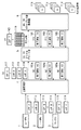
図4はデジタルプリント部の構成の一例を示すブロック図である。
[Digital Print System Configuration]
FIG. 4 is a block diagram showing an example of the configuration of the digital print unit.
ここには、ネットワーク38に接続されたプリントサーバ30、クライアントPC31と32、白黒MFP33、34及びカラーMFP35、36、37がそれぞれ1つまたは複数個接続されている。
Here, one or a plurality of
プリントサーバ30は、2つの役割を持っている。1つは、デジタルプリント部5の外部との情報の送受信である。ここで、入稿されるジョブの画像情報や設定情報等は、まず、プリントサーバ30に入力され、そのジョブが終了するとステータス等の情報を外部に知らせられる。もう1つは、デジタルプリント部5内部の管理制御である。ここでは、外部から入力されたジョブ及び、デジタルプリント部5の内部で発生したジョブが、プリントサーバ30にて一元管理されている。
The
また、デジタルプリント部5の内部にある全てのデバイスと全てのジョブの状況が監視できると共に、ジョブの一時停止、設定変更、印刷再開あるいは、ジョブの複製、移動、削除等の制御が行えるようになっている。
In addition, the status of all devices and all jobs in the
クライアントPC31、32は、入力されたアプリケーションファイルの編集、印刷指示、あるいは、プリントレディファイルの投入の役割と、プリントサーバ30内で管理されているデバイスやジョブの監視や制御の補佐する役割を持っている。
Each of the
白黒MFP33、34及びカラーMFP35、36、37は、スキャン、プリント、コピー等の様々な機能を有する画像形成装置である。ここで、カラーMFPと白黒MFPとでは、スピードやコスト等が異なるため、それぞれの用途に応じて使い分ける。また、カラーMFP37には、フィニッシャ装置が接続されている場合を示している。
The
[ポストプレス部のシステム構成]
図5はポストプレス部の構成の一例を示すブロック図である。
[Post-press system configuration]
FIG. 5 is a block diagram showing an example of the configuration of the post press section.
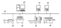
ポストプレス部6は、ポストプレスサーバ40、クライアントPC41、42、及び、紙折り機43、断裁機44、中綴じ製本機45、くるみ製本機46に代表される後処理装置で構成されている。
The
まず、ポストプレスサーバ40は、後処理工程を統括管理するコンピュータであり、受注サーバ21にて受け付けたジョブの指示やMISサーバ20から出力されるジョブの指示等に基づいて、ポストプレス部6で仕上げ可能な後処理条件を作成する。そして、エンドユーザの要求通りの後処理(仕上げ処理)工程の指示を行う。一般には、ポストプレスサーバ40は、ポストプレス部6の外部とJDF等の情報交換手段を使って、ポストプレス部6の内部コマンドやステータスでそれぞれの後処理装置と情報交換している。
First, the
後処理装置は、大きく3つの種類に分類することができ、以下のように定義する。 Post-processing devices can be broadly classified into three types, which are defined as follows.
1)インラインフィニッシャ:紙パスがMFPと物理的に接続されており、かつ、操作指示や状況確認もMFPと電気的に接続されている後処理装置。以降では、フィニッシャ装置とのみ述べた場合には、インラインフィニッシャ装置を指すものとする。 1) Inline finisher: a post-processing device in which the paper path is physically connected to the MFP, and operation instructions and status confirmation are also electrically connected to the MFP. Hereinafter, when only the finisher device is described, the term “inline finisher device” is used.
2)ニアラインフィニッシャ:紙パスはMFPと接続されておらず、作業者(オペレータ)が出力物の運搬、出力物の設定を行うが、操作指示や状況確認はネットワーク等の通信手段を介して電気的に情報送受可能な後処理装置。 2) Nearline finisher: The paper path is not connected to the MFP, and the operator (operator) carries the output material and sets the output material. However, the operation instructions and status confirmation are performed via communication means such as a network. Post-processing device that can send and receive information automatically.
3)オフラインフィニッシャ:紙パスも操作指示や状況確認等の通信手段もMFPと全く接続されておらず、作業者が出力物の運搬、出力物の設定、手作業での操作入力を行い、機器自体が発する状況報告を作業者が目視で確認する後処理装置。 3) Offline finisher: Neither the paper path nor the communication means such as operation instructions and status confirmation are connected to the MFP at all. The operator carries the output, sets the output, and manually inputs the operation. Post-processing device that allows workers to visually check the status report issued by itself.
更に、後処理装置は、出力原稿に対する様々なシート加工処理を、MFP等の画像形成装置にて印刷された出力原稿に対して施す後処理工程を実行する。この後処理工程には、断裁処理工程、中綴じ製本処理工程、くるみ製本処理工程、紙折処理工程、穴あけ処理工程、封入処理工程、帳合処理工程等がある。この後処理装置は、エンドユーザに提供する製本形態に加工するように制御する。 Further, the post-processing device executes post-processing steps for performing various sheet processing processes on the output document on the output document printed by an image forming apparatus such as an MFP. This post-processing process includes a cutting process process, a saddle stitch bookbinding process process, a case binding process process, a paper folding process process, a punching process process, an enclosing process process, a check process process, and the like. This post-processing apparatus controls to process the bookbinding form provided to the end user.
ポストプレスサーバ40が管理するニアラインフィニッシャ(時には、オフラインフィニッシャも含めて)には、紙折機43、断裁機44、中綴じ製本機45、くるみ製本機46が含まれる。この他にも、ステイプラ、穴あけ機、封入機あるいは、帳合機(コレータ)を初めとして様々なものがある。そして、ポストプレスサーバ40は、これらのニアラインフィニッシャと予め決められたプロトコルで逐次ポーリング等でデバイスの状況やジョブの状況を把握し、ジョブの実行状況を管理する。
Nearline finishers (sometimes including offline finishers) managed by the
尚、実施形態は、上述の複数のシート処理をそれぞれ別々のシート処理装置により実行可能にする構成でも、複数種類のシート処理を1台のシート処理装置が実行可能にする構成でも良い。また、複数のシート処理装置の内のいずれかのシート処理装置を本システムに具備する構成でも良い。 The embodiment may be configured such that the above-described plurality of sheet processes can be executed by separate sheet processing apparatuses, or a plurality of types of sheet processing can be executed by one sheet processing apparatus. Further, the system may include any one of a plurality of sheet processing apparatuses.
また、PODシステムにおいて、全ての印刷ジョブがポストプレス部6で処理されるわけではない。フィニッシャ装置を持つカラーMFP37で後処理工程までも処理されても構わない。
Further, in the POD system, not all print jobs are processed by the
また、従来、商業印刷の分野では、ジョブチケットを使用した商業印刷ワークフローが提案されている。以降、図6〜図8を用いて、従来の商業印刷の分野でのPODシステムにおける「ジョブチケットによるワークフロー」とジョブチケットに関して、一例を示して説明する。 Conventionally, in the field of commercial printing, commercial printing workflows using job tickets have been proposed. Hereinafter, with reference to FIGS. 6 to 8, an example of the “workflow by job ticket” and the job ticket in the conventional POD system in the field of commercial printing will be described.
図6はジョブチケットにより実現されるワークフロー構成の一例を示す図である。 FIG. 6 is a diagram showing an example of a workflow configuration realized by a job ticket.
図6において、MISサーバ20は、受注から納品までのシステム全体のワークフローを管理すると共に、様々な経営情報や販売情報を統括的に管理するシステムである。このMISサーバ20には、ワークフローにおける作業指示が記述されたジョブチケットに相当するJDFデータ52を作成するためのJDF(Job Definition Format)作成アプリケーション51が構成されている。
In FIG. 6, the
プリントサーバ30は、デジタルプリント部5に投入されるジョブを受信すると共に、デジタルプリント部5全体を管理制御するためのサーバである。プリントサーバ30には、JDFデータ52を解釈するためのJDFパーサ53、PDF/PS等の各種PDLデータを処理するためのPDLコントローラ54が構成される。更には、プリントサーバ30には、MFP56等のプリンタエンジンにフィニッシャ装置58と接続するためのプリンタ/フィニッシャインターフェース55により構成される。
The
ジョブチケットによるワークフローは、以下のように実現される。 The workflow based on the job ticket is realized as follows.
MISサーバ20に受注ジョブ50が投入されると、作業者は、MISサーバ20にインストールされているJDF作成アプリケーション51により、ワークフローにおける作業指示が記述されたジョブチケットに相当するJDFデータ52を作成する。
When the
作成されたJDFデータ52がプリントサーバ30に渡されると、プリントサーバ30におけるJDFパーサ53がJDFデータ52を解釈して、デジタルプリント部5に対するジョブを実行する。例えば、JDFデータ52には、出力用紙サイズや両面片面印刷やN−up等の属性が指定されている。JDFデータ52の内容に従って、PDLコントローラ54がJDFデータ52により参照されるPDF/PS等のPDLデータを処理する。そして、これとともにプリンタ/フィニッシャインターフェース55を介してMFP56に対して印刷を実行する。
When the created
印刷実行によって出力原稿57がフィニッシャA58に搬送される。
The
ここで、JDFデータ52に、くるみ製本や中綴じ製本や断裁等の属性が指定されているならば、JDFデータ52の内容に従って、プリンタ/フィニッシャインターフェース55を介してフィニッシャA58に対して後処理を実行する。
If attributes such as case binding, saddle stitch binding, and cutting are specified in the
図7はPODシステムにおけるジョブチケットの構造の一例を示す図である。 FIG. 7 is a diagram showing an example of the structure of a job ticket in the POD system.
52は、JDFデータ全体を示している。61は、PDF等のコンテンツデータをどのように画像処理し、どのように配置するか等を示す複数のPrepress処理の指示群が記述されている。62は、Prepress処理において作成された画像データをどのように原稿に出力するか等を示す複数のPress処理の指示群が記述されている。63は、Press処理指示62に従って出力された原稿をくるみ製本等、どのように後処理するかを示す複数のPostPress処理の指示群が記述されている。
60は、Prepress処理指示61、Press処理指示62、PostPress処理指示63を一つの処理に纏めるCombined Process処理を示している。通常、デジタルプリントを司るカラーMFP37等では一回の印刷ジョブの入力に対して、Prepress処理、Press処理、PostPress処理まで実行終了した製本結果が唯一つの出力となる。
このように、一度のデータ入力に対して、Prepress処理+Press処理+PostPress処理までを同時に処理し、唯一つの出力を指示したい場合にCombined Processが使用される。Prepress・Press・PostPress処理の少なくとも2つ以上を所持するMFP等のデジタル画像形成装置に対する指示には、常に、このCombined Processが使用される。 As described above, the combined process is used when it is desired to simultaneously process the prepress process + press process + postpress process with respect to a single data input and to instruct only one output. This combined process is always used for an instruction to a digital image forming apparatus such as an MFP having at least two of the Prepress / Press / PostPress processes.
図8はPODシステムにおけるジョブチケットの構造の別例を示す図である。 FIG. 8 is a diagram showing another example of the structure of the job ticket in the POD system.
ジョブチケットを表現するJDFはXMLフォーマットで記述されており、ノードの階層構造によって表現できる。図8は、JDFによって製本の一例を示す階層図である。一方、図7は、JDF構造を実行プロセスの種類で示している。 The JDF that expresses the job ticket is described in the XML format and can be expressed by a hierarchical structure of nodes. FIG. 8 is a hierarchy diagram showing an example of bookbinding by JDF. On the other hand, FIG. 7 shows the JDF structure by the type of execution process.
「本全体」71を作成するには、表紙72を作ったり、中身73を作ったり、あるいは、それらを製本したりと様々な工程を経てエンドユーザに届けられる「本全体」71ができあがる。
In order to create the “whole book” 71, a “whole book” 71 that can be delivered to the end user through various processes, such as making a
JDFでは、出力物を構成する際に、物理的な出力物を作成する工程をプロダクトノード、プロダクトノードを作成するための処理工程をプロセスノードと呼んでいる。これに加えて、プロダクトノードを作成するための中間的段階の要素でいくつかのプロセスノードの集合体をプロセスグループノード(表紙の出力74、カラーページの出力75、白黒ページの出力76、本全体の製本処理77)と呼んでいる。
In JDF, when configuring an output product, a process for creating a physical output product is called a product node, and a process for creating a product node is called a process node. In addition to this, an intermediate stage element for creating a product node is a process group node (cover
また、図7におけるPrepress処理は、カラーページのRIP処理7aや白黒ページのRIP処理7cに対応する。また、Press処理は、表紙出力のプロセス1(78)、表紙のラミネート処理79、カラーページプリント処理7b、白黒ページプリント処理7dに対応する。更に、PostPress処理は、くるみ製本処理7e、断裁処理7fに対応する。
7 corresponds to the
次に、図9から図15を用いて、従来のPODシステムにおけるギャング(Gang)ジョブ印刷の一例を説明する。ここで、ギャングジョブとは、複数のジョブが同一ジョブとして実行されるジョブを意味するものである。 Next, an example of gang job printing in a conventional POD system will be described with reference to FIGS. Here, the gang job means a job in which a plurality of jobs are executed as the same job.
図9は図1のPODシステムの別構成例を示す図である。 FIG. 9 is a diagram showing another configuration example of the POD system of FIG.
図9では、工程管理部4はMISサーバ20、受注サーバ21、ファイルサーバ22で構成している。デジタルプリント部5は、カラーMFP37で構成している。また、ポストプレス部6は、ポストプレスサーバ40とニアラインフィニッシャ46で構成している。そして、図9のPODシステムでは、プリプレス部7が構成されていない場合を示している。90はLAN等のネットワークである。また、91はインタ−ネットである。
In FIG. 9, the
以降、本例では、ユーザA、ユーザB、ユーザCの名刺をギャングジョブで印刷する場合について説明する。 Hereinafter, in this example, a case where business cards of user A, user B, and user C are printed by a gang job will be described.
図10は、ギャングジョブにおけるカラーMFP37からの出力を示す一例である。
FIG. 10 is an example showing output from the
100から104はカラーMFP37の出力原稿である。100は、出力原稿全体がユーザA用の名刺が印刷されている原稿群である。101は、ユーザA用の名刺とユーザB用の名刺が混在している原稿である。102は、ユーザB用の名刺が印刷されている原稿群である。103は、ユーザB用の名刺とユーザC用の名刺が混在している原稿である。104は、ユーザC用の名刺のみが印刷されている原稿である。
本例では、ユーザが異なる同一種の3つのジョブをマージしたギャングジョブの例を示している。 In this example, an example of a gang job in which three jobs of the same type with different users are merged is shown.
また、105は、出力原稿中におけるユーザAの名刺が印刷されている領域を示している。106は、出力原稿中におけるユーザBの名刺が印刷されている領域を示している。107は、出力原稿中におけるユーザCの名刺が印刷されている領域を示している。
図11は図9のPODシステムにおいて、図10で示すギャングジョブがどのように処理されるかを説明するための図である。 FIG. 11 is a diagram for explaining how the gang job shown in FIG. 10 is processed in the POD system of FIG.
本例では、ユーザA、B、Cの3名からのジョブを処理する例を説明するので、図9の構成に、エンドユーザ環境2(ユーザB)及び110(ユーザC)を追加している。 In this example, an example in which jobs from three users A, B, and C are processed will be described. Therefore, end user environments 2 (user B) and 110 (user C) are added to the configuration of FIG. .
111はユーザAからPODシステムに送信されたJDFであるJDF−Aを示し、ユーザA用の名刺を作成する作業指示が記述されている。112はユーザAから送信されたコンテンツデータ(pdf−A)であり、ユーザAの名刺を表現する画像データが記録されている。このJDF−A111とコンテンツデータ(pdf−A)112を合わせてユーザA用の印刷ジョブが構成される。本例では、コンテンツデータをPDFデータとして説明する。
同様に、113はユーザBからPODシステムに送信されたJDFであるJDF−Bを示し、ユーザB用の名刺を作成する作業指示が記述されている。114はユーザBから送信されたコンテンツデータであり、ユーザBの名刺を表現する画像データが記録されている。このJDF−B113とコンテンツデータ(pdf−B)114を合わせてユーザB用の印刷ジョブが構成される。
Similarly, 113 indicates JDF-B, which is JDF transmitted from the user B to the POD system, and describes a work instruction for creating a business card for the user B. 114 is content data transmitted from the user B, in which image data representing the business card of the user B is recorded. The JDF-
115はユーザCからPODシステムに送信されたJDFであるJDF−Cを示し、ユーザC用の名刺を作成する作業指示が記述されている。116はユーザCから送信されたコンテンツデータであり、ユーザCの名刺を表現する画像データが記録されている。JDF−C115とコンテンツデータ(pdf−C)116を合わせてユーザC用の印刷ジョブが構成される。
これらの3つの印刷ジョブは、まず、受信サーバ21に送信され、受信サーバ21からJDFデータはMISサーバ20へ送信され、コンテンツデータはファイルサーバ22へ送信されて保存される。
These three print jobs are first transmitted to the
MISサーバ20では、送信された3つの印刷ジョブをマージして1つのギャングジョブを生成する。このギャングジョブ用のJDFが、JDF−X1(117)である。MISサーバ20は、JDF−X1(117)と、ファイルサーバ22に保存されているコンテンツデータ(pdf−A(112)、pdf−B(114)、pdf−C(116))をデジタルプリント部5のカラーMFP37へ送信する。
The
そして、カラーMFP37では、受信したJDF−X1(117)の指示に従って原稿の印刷処理を行う。全印刷原稿の出力終了後、カラーMFP37は、印刷原稿の出力処理まで終了したことをJDFに記録したJDF−X2(118)をポストプレス部6のポストプレスサーバ40へ送信る。また、カラーMFP37の出力原稿119は、オペレータがニアラインフィニッシャ46へ搬送してセットする。
Then, the
ポストプレス部6においては、原稿のセットが終了し、オペレータが断裁処理の開始を指示すると、ポストプレスサーバ40が受信したJDF−X2(118)の指示に従って断裁処理指示をニアラインフィニッシャ46へ送信し、断裁処理が実行される。断裁処理後に最終成果物として生成されるものが、ユーザA用の名刺11bに、ユーザB用の名刺11cに、ユーザC用の名刺11dである。
In the
全断裁処理が終了し、全ユーザ全員分の名刺の作成が終了すると、ポストプレスサーバ40は、ギャングジョブの終了通知11aをMISサーバ20へ送信し、ギャングジョブの処理が終了する。
When all the cutting processes are completed and the creation of business cards for all the users is completed, the
図12は、図11の処理の例を簡略化したものである。 FIG. 12 is a simplified example of the processing of FIG.
図12では、ジョブ処理は左側から右側へ、ジョブ終了通知は右側から左側へなされるように記述している。また、MISサーバ20と受注サーバ21とファイルサーバ22は記述を省略しているが、工程管理部4内に図11と同様に構成されているものとする。
In FIG. 12, the job processing is described from the left side to the right side, and the job end notification is described from the right side to the left side. Further, the
カラーMFP37に関しても同様にデジタルプリント部5内に構成されているものとし、ポストプレスサーバ40とニアラインフィニッシャ46に関してもポストプレス部6内に構成されているものとする。以降の説明では、データの流れを説明するために、図12のPODシステムの構成図を用いて説明を行う。
The
図13は、ユーザA、B、CからPODシステムに送信されたJDFである。ここでは、JDF−A111、JDF−B113、JDF−C115の詳細構成を説明する図である。JDFは、XML形式で記述され、各々の丸はXMLのノードを示している。 FIG. 13 is a JDF transmitted from the users A, B, and C to the POD system. Here, it is a figure explaining the detailed structure of JDF-A111, JDF-B113, and JDF-C115. JDF is described in an XML format, and each circle indicates an XML node.
JDF−A111は、2つのノード130、131から構成されている。ノード130は、JDFルートノードであり、ジョブの作成者や日付等のAudit情報に、ユーザAを示すJobID情報(「A」)が記録されている。ノード131は、ユーザA用処理指示ノードである。これには、Product Intent情報として印刷時のレイアウトを示すLayoutIntent情報に、このジョブで使用するpdf名称とロケーションを示すコンテンツ情報(「pdf−A」)が記録されている。
The JDF-
同様に、JDF−B113は、2つのノード132、133から構成されている。ノード132は、JDFルートノードであり、ジョブの作成者や日付等のAudit情報に、ユーザBを示すJobID情報(「B」)が記録されている。ノード133は、ユーザB用処理指示ノードである。これには、Product Intent情報として印刷時のレイアウトを示すLayoutIntent情報に、このジョブで使用するpdf名称とロケーションを示すコンテンツ情報(「pdf−B」)が記録されている。
Similarly, the JDF-
また、JDF−C115は、2つのノード134、135から構成されている。ノード134は、JDFルートノードであり、ジョブの作成者や日付等のAudit情報に、ユーザCを示すJobID情報(「C」)が記録されている。ノード135は、ユーザC用処理指示ノードである。これには、Product Intent情報として印刷時のレイアウトを示すLayoutIntent情報に、このジョブで使用するpdf名称とロケーションを示すコンテンツ情報(「pdf−C」)が記録されている。
The JDF-
図14は、MISサーバ20からカラーMFP37へに送信されたJDFであり、JDF−X1(117)の構成を説明する図である。
FIG. 14 is a diagram for explaining the configuration of JDF-X1 (117), which is JDF transmitted from the
JDF−X1(117)は、MISサーバ20において、JDF−A111とJDF−B113とJDF−C115をマージしたギャングジョブとして生成される。
JDF-X1 (117) is generated in the
JDF−X1(117)は、図示されるように、9個のノードから生成される。ノード140はJDFルートノードであり、Audit情報とギャングジョブXを示すJobID情報(「X」)が記録されている。ノード141はIntent情報のルートノードであり、このノード下には、ギャングジョブの元になるJDF−A、JDF−B、JDF−Cの情報がそのまま記録されている。
JDF-X1 (117) is generated from nine nodes as shown in the figure. The
ノード142はギャングジョブ処理指示ノードであり、複数の処理をまとめて実行する指示が記述されているCombinedProcessノードである。これには、Prepress指示、Press指示、PostPress指示が記述されており、また、使用するpdfファイル名とロケーションを示すコンテンツ情報(pdf−A、pdf−B、pdf−C)も記述されている。
A
図15は、カラーMFP37からポストプレスサーバ40へ送信されたJDFであり、JDF−X2(118)の構成を説明する図である。
FIG. 15 is a diagram for explaining the configuration of JDF-X2 (118), which is JDF transmitted from the
JDF−X2(118)の構造や指示内容には、JDF−X1(117)と基本的に違いがない。但し、JDF−X2(118)においては、カラーMFP37において処理終了した指示に対して、「実行済」のマークを記述している。本例では、ギャングジョブ処理指示ノード142下のPrepress指示とPress指示に「実行済」を意味する[済]のマークが記述されている。PostPress指示に関しては未実行なので、マークされていない。以降の処理では、この[済]マークの記述されている処理に関しては実行されない。
The structure and instruction content of JDF-X2 (118) is basically the same as JDF-X1 (117). However, in JDF-X2 (118), an “executed” mark is described in response to an instruction for completion of processing in the
そして、ユーザAに対しても、ユーザBに対しても、ユーザCに対しても、ギャングジョブの全処理が終了した後に、その終了の通知がなされることになる。 The user A, the user B, and the user C are notified of completion after completing all the processing of the gang job.
以上がPODシステムにおけるギャングジョブの基本的な処理手順である。 The above is the basic processing procedure of a gang job in the POD system.
ここで、従来のギャングジョブの処理手順は、ギャングジョブの全処理が終了しないと、それを構成するジョブの一部の処理が完了していても、その終了の通知がジョブの生成元になされず、処理効率の低下を招く可能性がある。 Here, in the conventional gang job processing procedure, if all the processing of a gang job is not completed, even if the processing of a part of the job constituting the gang job is completed, the end notification is made to the job generation source. Therefore, there is a possibility that the processing efficiency is lowered.
そこで、本発明では、ギャングジョブを構成するコンテンツとオリジナルジョブの関係を判断することにより、あるユーザ分のジョブ処理が終了した場合には、その終了通知(ジョブステータス情報)を該当するユーザに通知する構成について説明する。 Therefore, in the present invention, when the job processing for a certain user is completed by determining the relationship between the content constituting the gang job and the original job, the completion notification (job status information) is notified to the corresponding user. The structure to perform is demonstrated.
また、本発明では、あるユーザ分のジョブ処理が終了した場合には、そのジョブだけを先行して次処理に転送することにより、全ギャングジョブの処理が終了する前にユーザ毎に成果物を受け取ることができる構成について説明する。 In addition, in the present invention, when job processing for a certain user is completed, only the job is transferred to the next processing in advance, so that the deliverables can be obtained for each user before the processing of all gang jobs is completed. A configuration that can be received will be described.
<実施形態1>
本発明の一実施形態である実施形態1について、図9、図10、図12〜図14、図16〜図22までを用いて説明する。
<
図9は基本構成の例でも用いたが、本発明においてもPODシステム構成の一例を示すブロック図として説明する。図10も同様に、基本構成の例でも用いたが、本発明においてもギャングジョブにおけるカラーMFP37からの出力を示す一例として説明する。
Although FIG. 9 was used in the example of the basic configuration, the present invention will be described as a block diagram showing an example of the configuration of the POD system. Similarly, FIG. 10 is used in the example of the basic configuration, but the present invention will be described as an example showing the output from the
図12も同様に、基本構成の例でも用いたが、本発明においても図9のPODシステム構成のブロック図と同じ構成を示すブロック図として説明する。但し、図12のJDF−Aやpdf−AやJDF−X1等で説明されたデータフローに関しては、基本構成の説明なので、本実施形態においては以降で改めて説明を行う。 Similarly, FIG. 12 is used in the basic configuration example, but the present invention will be described as a block diagram showing the same configuration as the block diagram of the POD system configuration in FIG. However, since the data flow described in JDF-A, pdf-A, JDF-X1, and the like in FIG. 12 is a description of the basic configuration, this embodiment will be described later.
図13も同様に、基本構成の例でも用いたが、本発明においてもユーザA、B、CからPODシステムに送信されたJDFを説明する図として説明する。図14も同様に、基本構成の例でも用いたが、本発明においてもMISサーバ20からカラーMFP37へに送信されたJDFであるJDF−X1の構成を説明する図として説明する。
13 is also used in the example of the basic configuration, but in the present invention, it will be described as a diagram for explaining JDF transmitted from the users A, B, and C to the POD system. Similarly, FIG. 14 is also used in the example of the basic configuration. In the present invention, the configuration of JDF-X1, which is JDF transmitted from the
図16は本発明の実施形態1におけるジョブの処理フローを説明する図である。 FIG. 16 is a diagram illustrating a job processing flow according to the first embodiment of the present invention.
JDF−A、B、C(111、113、115)、JDF−X1(117)とpdf−A、B、C(112、114、116)に関しては、従来技術の説明と同じものであり、JDF−X1(117)はMISサーバ20で生成されたギャングジョブである。JDF−Y(160)はデジタルプリント部5内のカラーMFP37で作成されたJDFである。この中には、ギャングジョブを構成するユーザ毎にポストプレス処理が終了したならば、カラーMFP37にその終了通知を行うように指示された作業手順が記述されている。このJDF−Y(160)の生成方法に関しては、後で説明を行う。
JDF-A, B, C (111, 113, 115), JDF-X1 (117) and pdf-A, B, C (112, 114, 116) are the same as those described in the prior art. -X1 (117) is a gang job generated by the
119はカラーMFP37から出力されたギャングジョブの出力物であり、従来技術で説明したものと同様である。11b、11c、11dも従来技術で説明したものと同様である。つまり、実施形態1でも、11bはユーザAの成果物である名刺を、11cはユーザBの成果物である名刺を、11dはユーザCの成果物である名刺を示している。
161はユーザAの成果物である名刺11bが作成し終わった時に、ポストプレス部6のポストプレスサーバ40からカラーMFP37へ送信される終了通知−A1である。この通知は、JDF−Y160の指示に従ってなされる。
また、同様に、163はユーザBの成果物である名刺11cが作成し終わった時に、ポストプレス部6のポストプレスサーバ40からカラーMFP37へ送信される終了通知−B1である。165はユーザCの成果物である名刺11dが作成し終わった時に、ポストプレス部6のポストプレスサーバ40からカラーMFP37へ送信される終了通知−C1である。
Similarly,
終了通知−A2(162)は、終了通知−A1(161)を受けて、カラーMFP37から工程管理部4のMISサーバ20へ通知されるユーザAのジョブ処理の終了通知である。同様に、終了通知−B2(164)は、終了通知−B1(163)を受けて、カラーMFP37から工程管理部4のMISサーバ20へ通知されるユーザBのジョブ処理の終了通知である。終了通知−C2(166)は、終了通知−C1(165)を受けて、カラーMFP37から工程管理部4のMISサーバ20へ通知されるユーザCのジョブ処理の終了通知である。
The end notification-A2 (162) is a job processing end notification of the user A notified from the
図17は、図16のデータフローの処理順番を説明する図である。処理順番を、図中では、(1)〜(12)で示してあり、数字の昇順に処理がなされていく。 FIG. 17 is a diagram for explaining the processing order of the data flow of FIG. The processing order is indicated by (1) to (12) in the figure, and processing is performed in ascending order of numbers.
(1)はジョブの受信を示し、デジタルプリント部5は、MISサーバ20からユーザA/B/Cのジョブがマージされたギャングジョブ(JDF−X1(117))を受信する。
(1) indicates reception of a job, and the
(2)はJDF−Y(160)の作成を示し、デジタルプリント部5は、ギャングジョブ(JDF−X1(117))からJDF−Y(160)を作成する。JDF−Y(160)には、ユーザA用の断裁処理とその終了をデバイスへ返却する指示、ユーザB用の断裁処理とその終了をデバイスへ返却する指示、ユーザC用の断裁処理とその終了をデバイスへ返却する指示が記述されている。JDF−Y(160)の構造、作成方法に関しては後述する。
(2) shows creation of JDF-Y (160), and the
(3)は原稿の出力を示し、デジタルプリント部5にてギャングジョブ(JDF−X1(117))のPrepress(プリプレス)処理、Press(プレス)処理を実行する。
(3) indicates the output of the original, and the
(4)はギャングジョブのニアラインフィニッシャへの送信を示し、ギャングジョブ(JDF−Y(160))をニアラインフィニッシャへ送信する。 (4) indicates transmission of a gang job to the nearline finisher, and the gang job (JDF-Y (160)) is transmitted to the nearline finisher.
(5)は出力原稿をニアラインフィニッシャへセットを示し、オペレータは、デバイスから出力された原稿をニアラインフィニッシャへセットする。 (5) indicates that the output original is set to the nearline finisher, and the operator sets the original output from the device to the nearline finisher.
(6)は断裁処理の実行を示し、オペレータは、ニアラインフィニッシャにて断裁処理を実行する。 (6) shows the execution of the cutting process, and the operator executes the cutting process with the nearline finisher.
(7)は終了通知の送信を示し、ユーザA分の断裁処理が終了すると、JDF−Y(160)の指示に従って、ポストプレス部6は、ユーザAのジョブの終了通知をデジタルプリント部5へ送信する。
(7) indicates transmission of an end notification. When the cutting process for the user A is completed, the
(8)は終了通知の送信を示し、デジタルプリント部5は、工程管理部4のMISサーバ20へユーザAのジョブの終了通知を送信する。
(8) indicates transmission of an end notification, and the
(9)は終了通知の送信を示し、ユーザB分の断裁処理が終了すると、JDF−Y(160)の指示に従って、ポストプレス部6は、ユーザBのジョブの終了通知をデジタルプリント部5へ送信する。
(9) indicates transmission of an end notification. When the cutting process for the user B is completed, the
(10)は終了通知の送信を示し、デジタルプリント部5は、工程管理部4のMISサーバ20へユーザBのジョブの終了通知を送信する。
(10) indicates transmission of an end notification, and the
(11)は終了通知の送信を示し、ユーザC分の断裁処理が終了すると、JDF−Y(160)の指示に従って、ポストプレス部6は、ユーザCのジョブの終了通知をデジタルプリント部5へ送信する。
(11) indicates transmission of an end notification. When the cutting process for the user C is completed, the
(12)は終了通知の送信を示し、デジタルプリント部5は、工程管理部4のMISサーバ20へユーザCのジョブの終了通知を送信する。
(12) indicates transmission of an end notification, and the
図18は、JDF−Y(160)の構成を説明する図である。 FIG. 18 is a diagram illustrating the configuration of JDF-Y (160).
このJDF−Y(160)は、JDF−X1(117)をベースにして、カラーMFP37で生成されるJDFである。
This JDF-Y (160) is a JDF generated by the
ノード130〜135と140に関しては、図14の構成と同様である。180は、図14のノード142と同様のギャングジョブ処理指示ノードであり、Prepress指示、Press指示、PostPress指示、pdf−Aとpdf−Bとpdf−Cを示すコンテンツ情報が記述されている。但し、ここでは、PostPress指示には、PostPress処理をしなくても良いこと(処理の実行済であること)を示す「済」が記述されている。つまり、ノード180は、ノード142をそのままコピーしているが、PostPress処理の実行の要否を示すPostPress指示にだけは、処理不要のマークが付加して作成されている。
The
以降のノード181〜184は、カラーMFP37によって新規に作成されたノードである。
ノード181は、ProcessGroupノードを示し、ノード182から184を束ねている。
A
ノード182は、ユーザA用処理指示ノードを示し、PostPress指示と終了通知指示とユーザAを示すJobID(「A」)が記述されている。このノード182には、ユーザA分の名刺だけを作成する断裁指示であるPostPress指示、PostPress処理が終了したならばカラーMFP37に終了通知を行う指示である終了通知指示が記録されている。更には、ノード182には、終了通知の際に付加するジョブの種類を示すJobIDが記録されている。この指示に従って、ポストプレス部6は、断裁処理や終了通知の処理を行う。このPostPress指示の作成方法に関しては、後述する。
The
同様に、ノード183は、ユーザB用処理指示ノードを示し、PostPress指示、終了通知指示、ユーザBを示すJobID(「B」)が記述されている。また、ノード184は、ユーザC用処理指示ノードを示し、PostPress指示、終了通知指示、ユーザCを示すJobID(「C」)が記述されている。
Similarly, the
ここで、JDF−X1(117)とJDF−Y(160)の違いは、次のようになっている。つまり、JDF−X1(117)に記述されていたPostPress指示を「済」に変更し、かつProcessGroupノード181(5)を新たに作成し、そのノード下に以下の3つの指示ノード182〜184を作成することである。
Here, the difference between JDF-X1 (117) and JDF-Y (160) is as follows. In other words, the PostPress instruction described in JDF-X1 (117) is changed to “Done”, and a ProcessGroup node 181 (5) is newly created, and the following three
一つ目は、ユーザA用のPostPress(断裁処理)指示と終了通知指示を含むノード182(A3)である。二つ目は、ユーザB用のPostPress(断裁処理)指示と終了通知指示を含むノード183(B3)である。三つ目は、ユーザC用のPostPress(断裁処理)指示と終了通知指示を含むノード184(C3)である。それ以外の構成は、JDF−X1(117)と同様である。 The first is a node 182 (A3) including a PostPress (cutting process) instruction for user A and an end notification instruction. The second is a node 183 (B3) including a PostPress (cutting process) instruction for user B and an end notification instruction. The third is a node 184 (C3) including a PostPress (cutting process) instruction for user C and an end notification instruction. The other configuration is the same as that of JDF-X1 (117).
尚、終了通知指示には、その通知先として、例えば、メールアドレスあるいは装置のIPアドレス等のアドレス情報であり、通知方法としては、例えば、メールあるいはメッセージダイアログによって実現される。 The end notification instruction includes, for example, an e-mail address or address information such as the IP address of the apparatus as the notification destination, and the notification method is realized by e-mail or a message dialog, for example.
次に、図19と図20を用いて、カラーMFP37におけるユーザ毎の断裁処理指示(PostPress指示)の作成方法に関して説明する。
Next, a method of creating a cutting process instruction (PostPress instruction) for each user in the
図19は、MISサーバ20から受信したJDF−X1(117)において、コンテンツ情報とギャングジョブになる前のオリジナルジョブの関係情報を抽出する方法を示す図である。
FIG. 19 is a diagram showing a method for extracting the relationship information between the content information and the original job before becoming a gang job in JDF-X1 (117) received from the
ノード142には、MISサーバ20からカラーMFP37に対して、Imposition指示(コンテンツをどのようにレイアウトするかの指示)を含むPrepress指示、Press指示が記述されている。これに加えて、PostPress指示(断裁方法、パッケージング方法等)、コンテンツ情報(使用するコンテンツ名称、そのロケーション)が記述されている。
The
一方、オリジナルのJDFを記録したIntentノード141下からは、どのユーザのジョブで、どのコンテンツ(本実施形態では、PDF)を使用しているかのコンテンツ情報190〜192を取得できる。よって、このコンテンツ情報190〜192から、どのユーザ毎の成果物を作成している作業かどうかを判断できる。
On the other hand,
図20は、MISサーバ20から受信したJDF−X1(117)において、コンテンツ情報とそれぞれのコンテンツがどのページのどの位置にレイアウトされるかの関係情報を抽出する方法を示す図である。
FIG. 20 is a diagram showing a method for extracting the relationship information about the content information and the position where each content is laid out in the JDF-X1 (117) received from the
200は、ギャングジョブ処理指示ノード142全体を示している。201は、Prepress処理指示部を示し、202はPress処理指示部を示し、203はPostPress処理指示部を示している。
また、205〜207はコンテンツ毎のレイアウト情報を示し、コンテンツの各々のページがどのページのどの位置にレイアウトされて出力されるかを指示している。209は、出力原稿のページ番号を示すページ情報を示し、20aはそのページのどの位置にレイアウトするかの位置情報を示し、20bはどのコンテンツのどのページのオブジェクトを使用するかのコンテンツ情報を示している。ページ情報209、位置情報20a、コンテンツ情報20bで1レコードが構成され、これがコンテンツのページ分の指示情報としてレイアウト情報205内に記録される。
同様に、20cは出力原稿のページ番号を示すページ情報を示し、20dはそのページのどの位置にレイアウトするかの位置情報を示し、20eはどのコンテンツのどのページのオブジェクトを使用するかのコンテンツ情報を示している。また、20fは出力原稿のページ番号を示すページ情報を示し、20gはそのページのどの位置にレイアウトするかの位置情報を示し、20hはどのコンテンツのどのページのオブジェクトを使用するかのコンテンツ情報を示している。 Similarly, 20c indicates page information indicating the page number of the output document, 20d indicates position information on which position of the page is laid out, and 20e indicates content information indicating which page of which content is used. Is shown. 20f indicates page information indicating the page number of the output document, 20g indicates position information on which position of the page is laid out, and 20h indicates content information indicating which page of which content is used. Show.
208は、各コンテンツ情報を記録するコンテンツ情報記録部(コンテンツリスト)を示している。コンテンツ情報記録部208において、20iにはpdf−Aのファイル名称とロケーションが示されており、20jにはpdf−Bのファイル名称とロケーションが示されており、20kにはpdf−Cのファイル名称とロケーションが示されている。
コンテンツ情報20b、20e及び20hは、コンテンツ情報記録部208中の情報として記録されている。よって、どのコンテンツが出力原稿のどの位置にレイアウトされているかが分かるので、JDF−X1(117)のレイアウト情報から、ユーザ毎のコンテンツ位置情報を抽出することにより、JDF−Y(160)のユーザ毎の断裁指示を作成することができる。
The
次に、デジタルプリント部5とポストプレス部6とにおける処理について、図21及び図22のフローチャートを用いて説明する。
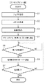
Next, processing in the
まず、デジタルプリント部5における処理について、図21及び図17を用いて説明する。
First, processing in the
図21は本発明の実施形態1におけるデジタルプリント部の処理を説明するフローチャートである。 FIG. 21 is a flowchart for explaining processing of the digital printing unit according to the first embodiment of the present invention.
ステップS1で、MISサーバ20からジョブを受信する。これは、図17の(1)に対応する。次に、ステップS2で、カラーMFP37にてJDF−X1(117)をベースにしてJDF−Y(160)を作成する。これは、図17の(2)に対応する。
In step S1, a job is received from the
次に、ステップS3で、ステップS2で作成したJDF−Y(160)の作業手順に従って、原稿を出力する。これは、図17の(3)に対応し、出力原稿は、例えば、図10となる。次に、ステップS4で、ギャングジョブであるJDF−Y(160)をポストプレス部6のポストプレスサーバ40へ送信する。これは、図17の(4)に対応する。
Next, in step S3, the document is output according to the work procedure of JDF-Y (160) created in step S2. This corresponds to (3) in FIG. 17, and the output document is, for example, FIG. Next, JDF-Y (160) which is a gang job is transmitted to the
次に、ステップS5で、ポストプレスサーバ40からの終了通知を受信したか否かを判定する。終了通知を受信していない場合(ステップS5でNO)、受信するまで待機する。一方、終了通知を受信した場合(ステップS5でYES)、ステップS6に進む。これは、図17の(7)、(9)、(11)に対応する。
Next, in step S5, it is determined whether an end notification from the
ステップS6で、受信した終了通知に従って、MISサーバ20へ終了通知を送信する。これは、図17の(8)、(10)、(12)に対応する。
In step S6, an end notification is transmitted to the
そして、ステップS7で、ギャングジョブの全処理が終了したか否かを判定する。ギャングジョブの全処理が終了していない場合(ステップS7でNO)、ステップS5へ戻る。一方、ギャングジョブの全処理が終了している場合(ステップS7でYES)、処理を終了する。 In step S7, it is determined whether or not all the processing of the gang job has been completed. If all the processing of the gang job has not ended (NO in step S7), the process returns to step S5. On the other hand, when all the processes of the gang job have been completed (YES in step S7), the process is terminated.
次に、ポストプレス部6における処理を、図22及び図17を用いて説明する。
Next, the process in the
図22は本発明の実施形態1におけるポストプレス部の処理を説明するフローチャートである。 FIG. 22 is a flowchart for explaining the processing of the post press section in the first embodiment of the present invention.
ステップS21で、ギャングジョブをカラーMFP37から受信したか否かを判定する。受信していない場合(ステップS21でNO)、受信するまで待機する。一方、受信した場合(ステップS21でYES)、ステップS22に進む。
In
ステップS22で、オペレータがカラーMFP37の出力トレイに排紙されている出力原稿を取り出し、ニアラインフィニッシャへセットしたことを検出する。これは、図17の(5)に対応する。次に、ステップS23で、JDF−Y(160)の指示に従って断裁処理を実行する。これは、図17の(6)に対応する。
In step S <b> 22, it is detected that the operator has taken out the output document discharged to the output tray of the
次に、ステップS24で、あるユーザ分の断裁処理が終了したか否かを判定する。終了していない場合(ステップS24でNO)、ステップS23へ戻る。一方、終了している場合(ステップS24でYES)、ステップS25に進む。 Next, in step S24, it is determined whether or not the cutting process for a certain user has been completed. If not completed (NO in step S24), the process returns to step S23. On the other hand, if it has been completed (YES in step S24), the process proceeds to step S25.
ステップS25で、あるユーザ分の断裁処理が終了したことを示す終了通知をカラーMFP37へ送信する。これは、図17の(7)、(9)、(11)に対応する。
In step S 25, an end notification indicating that the cutting process for a certain user has ended is transmitted to the
そして、ステップS26で、全ユーザ分の断裁処理が終了したか否かを判定する。断裁処理が終了していない場合(ステップS26でNO)、ステップS23へ戻る。一方、断裁処理が終了している場合(ステップS26でYES)、処理を終了する。 In step S26, it is determined whether the cutting process for all users has been completed. If the cutting process has not ended (NO in step S26), the process returns to step S23. On the other hand, when the cutting process has ended (YES in step S26), the process ends.
尚、実施形態1では、図17に示すように、全処理が順番に実行されるものとして記述しているが、ポストプレス部6の処理とカラーMFP37の処理が並行処理されるように構成しても構わない。例えば、図17では、カラーMFP37からMISサーバ20へユーザAの終了通知−A2の通知処理が実行されてから、ニアラインフィニッシャにおいて次の断裁処理が実行され、終了通知−B1がなされるように説明している。これを、例えば、ニアラインフィニッシャは、終了通知−A1を送信後、直ちに次の断裁処理を開始しても構わない。
In the first embodiment, as shown in FIG. 17, it is described that all the processes are executed in order. However, the process of the
また、実施形態1では、作業手順を示すデータとしてJDF、コンテンツとしてPDFを用いて説明しているが、その他のフォーマットのデータでも構わないことは言うまでもない。ここで、PDFやJDFのデータフォーマットは公開されており、その意味、その解釈方法、その生成方法に関しては既知の技術として詳細な説明は省略している。 In the first embodiment, JDF is used as data indicating a work procedure and PDF is used as content. However, it goes without saying that data in other formats may be used. Here, the data formats of PDF and JDF are open to the public, and detailed descriptions of their meaning, interpretation method, and generation method are omitted as known techniques.
また、実施形態1では、ギャングジョブの作成は、MISサーバ20で行う場合に関して説明しているが、他の受注サーバ等の工程管理部の他の装置や、カラーMFP37等のデジタルプリント部5の他の装置で作成しても構わない。
In the first embodiment, the gang job is created by the
また、実施形態1では、ポストプレス部6からの終了通知は、デジタルプリント部5に送信するように説明しているが、工程管理部4に送信するように作成しても構わない。
In the first embodiment, the end notification from the
また、実施形態1では、ポストプレス部6における処理を断裁処理のみとして説明しているが、ポストプレス部6における処理を断裁処理とユーザ毎に名刺を袋詰めにするパッケージング処理としても構わない。この場合には、実施形態1における断裁処理後の処理は、終了通知ではなく、次工程であるパッケージング処理部へのジョブ転送となる。
In the first embodiment, the process in the
以上説明したように、実施形態1によれば、複数のジョブがマージされたギャングジョブにおいて、処理の終了通知を、そのジョブの生成元となるユーザ毎に行うことができるようになり、ユーザ毎の処理待ち時間を減少させることが可能になる。 As described above, according to the first embodiment, in a gang job in which a plurality of jobs are merged, a process end notification can be performed for each user who is a generation source of the job. It becomes possible to reduce the processing waiting time.
また、一旦、ギャングジョブに変更された後でも、ユーザ毎に次工程処理にジョブ転送を行うことができるようになり、ユーザ単位でのトータル作業処理時間を減らすことが可能になる。 Further, even after the job is changed to a gang job, the job can be transferred to the next process for each user, and the total work processing time for each user can be reduced.
<実施形態2>
実施形態2に関して、図23〜図26を用いて説明する。
<
The second embodiment will be described with reference to FIGS.
実施形態2では、ギャングジョブの作成をカラーMFP37で行い、ポストプレス部6からの終了通知は工程管理部4へ送信する構成に関して説明する。
In the second embodiment, a configuration in which a gang job is created by the
図23は本発明の実施形態2におけるジョブの処理フローを説明する図である。 FIG. 23 is a diagram illustrating a job processing flow according to the second embodiment of the present invention.
実施形態2では、ユーザA〜Cそれぞれからのジョブを構成する、JDF−A、B、C(111、113、115)と、pdf−A、B、C(112、114、116)は、デジタルプリント部5のカラーMFP37まで送信されている。
In the second embodiment, JDF-A, B, and C (111, 113, and 115) and pdf-A, B, and C (112, 114, and 116) that constitute jobs from users A to C are digital The image is transmitted to the
また、カラーMFP37では、受信した3ユーザ分のジョブからギャングジョブであるJDF−G230を作成し、その出力処理後に出力成果物119とともにポストプレス部6へ送信する。JDF−G230の詳細に関しては以降で説明する。そして、各ユーザ毎の断裁処理が終了する毎に、ポストプレス部6のポストプレスサーバ40からは、ジョブA終了通知231、ジョブB終了通知232、ジョブC終了通知233を工程管理部4のMISサーバ20にそれぞれ送信する。
Further, the
図24は本発明の実施形態2のギャングジョブであるJDF−Gの構成を説明する図である。 FIG. 24 is a diagram illustrating the configuration of JDF-G, which is a gang job according to the second embodiment of the present invention.
実施形態2では、図13で示された元のジョブ情報である情報を記録しない構成として説明する。 In the second embodiment, a description will be given assuming that the original job information shown in FIG. 13 is not recorded.
240は、JDF−Gの全体を示している。241は、Prepress処理とPress処理を一度に実行するように構成したCombinedProcess指示部を示している。245には、ギャングジョブのPrepress処理の指示が記述されている。また、246には、ギャングジョブのPress処理の指示が記述されている。
Reference numeral 240 denotes the entire JDF-G. Reference numeral 241 denotes a combined process instruction unit configured to execute the prepress process and the press process at a time.
また、242は、ユーザA用の成果物の生成と通知処理を記述したユーザA用指示部を示している。247には、ユーザA用の成果物を生成するためのPostPress処理指示が記述されている。248には、ユーザA用の処理終了通知指示が記述されている。
同様に、243は、ユーザB用の成果物の生成と通知処理を記述したユーザB用指示部を示している。249には、ユーザB用の成果物を生成するためのPostPress処理指示が記述されている。24aには、ユーザB用の処理終了通知指示が記述されている。
Similarly,
また、同様に、244は、ユーザC用の成果物の生成と通知処理を記述したユーザC用指示部を示している。24bには、ユーザC用の成果物を生成するためのPostPress処理指示が記述されている。24cには、ユーザC用の処理終了通知指示が記述されている。
Similarly,
実施形態2では、ギャングジョブであるJDF−Gにおいて使用するコンテンツとそのレイアウトを指示したPrepress処理指示部245の生成は、元のジョブの指示であるJDF−A、B、Cからオペレータが行うものとする。但し、Prepress指示部245からPostPress処理指示部247、249、24bの生成に関しては、実施形態1と同じ方法で行うものとする。
In the second embodiment, the generation of the Prepress
図25は、JDF−Gの構成をXMLのノード階層構造として説明した図である。 FIG. 25 is a diagram illustrating the configuration of JDF-G as an XML node hierarchical structure.
241から244までは、図24中の同一参照番号の構成要素に対応する。ユーザA用処理指示ノード242には、ユーザAのジョブを示すJobID(「A」)が記録されている。ユーザB用処理指示ノード243には、ユーザBのジョブを示すJobID(「B」)が記録されている。ユーザC用処理指示ノード244には、ユーザCのジョブを示すJobID(「C」)が記録されている。
次に、実施形態2におけるデジタルプリント部5の処理について、図26を用いて説明する。
Next, processing of the
図26は本発明の実施形態2におけるデジタルプリント部の処理を説明するフローチャートである。 FIG. 26 is a flowchart for explaining processing of the digital printing unit according to the second embodiment of the present invention.
ステップS30で、MISサーバ20からジョブを受信する。カラーMFP37は、MISサーバ20からユーザAのジョブ(JDF−A)を受信し、受信ジョブをギャングジョブ用キューに保存する。
In step S30, a job is received from the
ステップS31で、ジョブの数やジョブのサイズ等の予めシステムに登録された判断基準に従って、ギャングジョブを生成するか否かを判定する。ギャングジョブを生成しない場合、ステップS30に戻り、次ジョブの受信を行う。実施形態2では、カラーMFP37は、MISサーバ20から次のジョブ(ユーザB、ユーザCのそれぞれのJDF−B、JDF−C)を受信する。
In step S31, it is determined whether or not a gang job is to be generated in accordance with determination criteria previously registered in the system, such as the number of jobs and job size. If no gang job is generated, the process returns to step S30 to receive the next job. In the second embodiment, the
一方、ギャングジョブを生成する場合(ステップS31でYES)、ステップS32に進み、これまでにギャングジョブ用キューにキューイングされたジョブを取得する。次に、ステップS33で、ギャングジョブ用キューに保存されたジョブ群を用いて、ギャングジョブを生成する。実施形態2では、受信したジョブJDF−A、JDF−B、JDF−Cをマージしてギャングジョブ(JDF−G)を生成するものとする。ギャングジョブには、ユーザ毎のジョブのPostPress処理の終了時に、MISサーバ20へ終了通知を行う指示が記録される。
On the other hand, if a gang job is to be generated (YES in step S31), the process proceeds to step S32, and the jobs queued in the gang job queue so far are acquired. Next, in step S33, a gang job is generated using the job group stored in the gang job queue. In the second embodiment, it is assumed that a gang job (JDF-G) is generated by merging received jobs JDF-A, JDF-B, and JDF-C. In the gang job, an instruction to notify the
次に、ステップS34で、カラーMFP37においてJDF−Gの作業手順に従って、出力原稿のラスタデータを生成するPrepress処理を実行する。次に、ステップS35で、Prepress処理で生成されたラスタイメージデータを使用してPress処理を実行する。
In step S34, the
ステップS36で、全ジョブのPress処理が終了したか否かを判定する。終了していない場合(ステップS36でNO)、ステップS35へ戻り、Press処理を継続する。一方、終了した場合(ステップS36でYES)、ステップS37に進み、ギャングジョブであるJDF−Gをポストプレス部6のポストプレスサーバ40へ送信して、デジタルプリント部5における処理を終了する。
In step S36, it is determined whether or not the press processing for all jobs has been completed. If not completed (NO in step S36), the process returns to step S35 and the press process is continued. On the other hand, if completed (YES in step S36), the process proceeds to step S37, where JDF-G, which is a gang job, is transmitted to the
ポストプレス部6における以降の処理は、実施形態1の場合とほぼ同様である。相違点としては、実施形態2では、通知先がMISサーバ20であることをJDF−Gに記述しているので、ユーザ毎の終了通知がMISサーバ20へ送信されることである。
Subsequent processing in the
以上説明したように、実施形態2によれば、実施形態1で説明した効果に加えて、用途や目的に応じて、ギャングジョブ中に処理の通知先を適応的に指定することが可能である。これにより、意図する通知先へ、ジョブの処理終了通知を送信することが可能となる。 As described above, according to the second embodiment, in addition to the effects described in the first embodiment, it is possible to adaptively specify a processing notification destination during a gang job according to the purpose and purpose. . As a result, it is possible to transmit a job processing end notification to an intended notification destination.
<実施形態3>
実施形態3に関して、図27及び図28を用いて説明する。
<
実施形態2では、カラーMFP37において全Press処理が終了した後に、ポストプレス部6に1度だけギャングジョブを送信する場合に関して説明している。これに対し、実施形態3では、カラーMFP37からポストプレス部6に送信するジョブもユーザ毎に分割する場合に関して説明する。
In the second embodiment, a case where a gang job is transmitted only once to the
図27は本発明の実施形態3におけるジョブの処理フローを説明する図である。 FIG. 27 is a diagram illustrating a job processing flow according to the third embodiment of the present invention.
実施形態3の処理フローについては、デジタルプリント部5内のカラーMFP37においてギャングジョブであるJDF−G230を作成するまでは、実施形態2の場合と同様である。実施形態3では、ポストプレス部6へジョブをユーザ毎に送信する。実施形態3では、ジョブを3回に分けてポストプレス部6へ送信している。
The processing flow of the third embodiment is the same as that of the second embodiment until the
ユーザA用の原稿の出力まで終了した時点で送信されるのが、JDF−A2(270)である。JDF−A2(270)には、ユーザA用の断裁処理と終了通知処理指示が記述されており、図25のユーザA用処理指示ノード242と同様の指示が記述されている。その時の出力原稿が273である。また、この出力原稿273は、図10の1枚目からL枚目までの出力原稿に対応する。
JDF-A2 (270) is transmitted when the output of the original for user A is completed. JDF-A2 (270) describes a cutting process for user A and an end notification process instruction, and an instruction similar to that of the
また、ユーザB用の原稿の出力まで終了した時点で送信されるのが、JDF−B2(271)である。JDF−B2(271)には、ユーザB用の断裁処理と終了通知処理指示が記述されており、図25のユーザB用処理指示ノード243と同様の指示が記述されている。その時の出力原稿が274である。また、この出力原稿274は、図10のL+1枚目からM枚目までの出力原稿に対応する。
Also, JDF-B2 (271) is transmitted when the output of the document for user B is completed. JDF-B2 (271) describes a cutting process and an end notification process instruction for user B, and describes the same instruction as that of the user B
また、ユーザC用の原稿の出力まで終了した時点で送信されるのが、JDF−C2(272)である。JDF−C2(272)には、ユーザC用の断裁処理と終了通知処理指示が記述されており、図25のユーザC用処理指示ノード244と同様の指示が記述されている。その時の出力原稿が275である。また、この出力原稿275は、図10のM+1枚目からN枚目までの出力原稿に対応する。
Also, JDF-C2 (272) is transmitted when the output of the user C original is completed. In JDF-C2 (272), a cutting process for user C and an end notification processing instruction are described, and an instruction similar to that of the user C
次に、実施形態3におけるデジタルプリント部5の処理について、図28を用いて説明する。
Next, processing of the
図28は本発明の実施形態3におけるデジタルプリント部の処理を説明するフローチャートである。 FIG. 28 is a flowchart for explaining processing of the digital printing unit according to the third embodiment of the present invention.
ステップS40〜ステップS44までは、実施形態2における図26のステップS30〜ステップS34までと同様であるので、その説明は省略する。 Since Steps S40 to S44 are the same as Steps S30 to S34 of FIG. 26 in the second embodiment, description thereof is omitted.
ステップS45で、作成されたJDF−Gの作業指示に従ってPress処理を実行する。ステップS46で、あるユーザ分までのPress処理が終了したか否かを判定する。終了していない場合(ステップS46でNO)、ステップS45に戻り、Press処理を継続する。 In step S45, the press process is executed in accordance with the created JDF-G work instruction. In step S46, it is determined whether or not the press process for a certain user has been completed. If not completed (NO in step S46), the process returns to step S45 and the press process is continued.
一方、終了した場合(ステップS46でYES)、ステップS47で、出力が終了したユーザに対応するポストプレス部6への作業指示であるJDFを生成する。実施形態3では、図27のJDF−G230の中で、出力の終了したユーザに対応するPostPress処理と通知処理が記述されているノードを、ポストプレス部6への指示として送信することとする。つまり、ユーザAのPress処理が終了した場合には、図25のノード242のみをポストプレス部6への作業指示として作成する。また、ユーザBのPress処理が終了した場合には、図25のノード243のみをポストプレス部6への作業指示として作成する。更に、ユーザCのPress処理が終了した場合には、図25のノード244のみをポストプレス部6への作業指示として作成する。
On the other hand, when the processing is completed (YES in step S46), in step S47, a JDF that is a work instruction to the
次に、ステップS48で、カラーMFP37は、ステップS47で作成したJDFをポストプレス部6のポストプレスサーバ40へ送信する。
Next, in step S48, the
ステップS49で、全ユーザ分のPress処理が終了したか否かを判定する。終了していない場合(ステップS49でNO)、ステップS45へ戻り、Press処理を継続する。一方、終了した場合(ステップS49でYES)、処理を終了する。 In step S49, it is determined whether or not the press processing for all users has been completed. If not completed (NO in step S49), the process returns to step S45 and the press process is continued. On the other hand, when the process is completed (YES in step S49), the process is terminated.
ポストプレス部6における以降の処理は、実施形態1の場合と同様であり、オペレータは、カラーMFP37の出力トレイに排出された出力原稿をニアラインフィニッシャへセットすることをユーザ分繰り返すことになる。実施形態3においては、ユーザA、B、Cの3名分のジョブがギャングジョブとして構成されているので、図27で示したように、オペレータは3回の出力原稿のセット作業を行うことになる。
The subsequent processing in the
以上説明したように、実施形態3によれば、1ユーザ分のジョブのPress処理が完了した時点で、そのジョブについてのPrePress処理へ移行するとともに、これに平行して、次のジョブのPress処理を実行することが可能となる。これにより、より効率的に処理を実行することが可能となる。 As described above, according to the third embodiment, when the press process for a job for one user is completed, the process proceeds to the PrePress process for the job, and in parallel with this, the press process for the next job is performed. Can be executed. Thereby, it becomes possible to perform a process more efficiently.
<実施形態4>
実施形態1〜3では、ポストプレス部6でのギャングジョブを構成するユーザ毎にポストプレス処理が終了したならば、デジタルプリント部5のカラーMFP37へその終了通知を行う構成としているがこれに限定されない。例えば、用途や目的によっては、カラーMFP37でのプリプレス処理及びプレス処理が終了したならば、つまり、原稿の出力(印刷)が完了した時点で、ポストプレス処理の実行に先だって、工程管理部4に通知を行う構成としても良い。
<
In the first to third embodiments, when the post press process is completed for each user constituting the gang job in the
以下、実施形態4の構成について説明する。 Hereinafter, the configuration of the fourth embodiment will be described.
図29は本発明の実施形態4におけるジョブの処理フロー及びその処理順番を説明する図である。尚、図29において、図16及び図17と共通部分については適宜省略する。 FIG. 29 is a diagram illustrating a job processing flow and processing order according to the fourth embodiment of the present invention. In FIG. 29, portions common to FIGS. 16 and 17 are omitted as appropriate.
図29において、JDF−Z(117a)はMISサーバ20で生成されたギャングジョブである。この中には、ギャングジョブを構成するユーザ毎にプリプレス処理及びプレスが終了したならば、MISサーバ20に通知を行うように指示された作業手順が記述されている。尚、このJDF−Z(117a)の生成方法に関しては、実施形態1のこのJDF−Y(160)の生成方法に準じて生成することができる。つまり、システム内の各装置で行う処理内容に応じて、JDFの記述内容を適宜適切な処理がなされるようにすれば良い。
In FIG. 29, JDF-Z (117a) is a gang job generated by the
終了通知−A2(162a)は、ユーザAのジョブによる原稿の出力が終わった時に、カラーMFP37から工程管理部4のMISサーバ20へ通知されるユーザAのジョブ処理の終了通知である。同様に、終了通知−B2(164a)は、ユーザBのジョブによる原稿の出力が終わった時に、カラーMFP37から工程管理部4のMISサーバ20へ通知されるユーザBのジョブ処理の終了通知である。終了通知−C2(166a)は、ユーザCのジョブによる原稿の出力が終わった時に、カラーMFP37から工程管理部4のMISサーバ20へ通知されるユーザCのジョブ処理の終了通知である。
An end notification-A2 (162a) is an end notification of user A's job processing notified from the
図29のデータフローの処理順番は、実施形態1の図17に示す処理順番が変更された構成となっている。 The processing order of the data flow in FIG. 29 has a configuration in which the processing order shown in FIG. 17 of the first embodiment is changed.
(1)はジョブの受信を示し、デジタルプリント部5は、MISサーバ20からユーザA/B/Cのジョブがマージされたギャングジョブ(JDF−Z(117a))を受信する。
(1) indicates reception of a job, and the
(2)はJDF−Y(160)の作成を示し、デジタルプリント部5は、ギャングジョブ(JDF−Z(117a))からJDF−Y(160)を作成する。JDF−Y(160)には、ユーザA用の断裁処理とその終了をデバイスへ返却する指示、ユーザB用の断裁処理とその終了をデバイスへ返却する指示、ユーザC用の断裁処理とその終了をデバイスへ返却する指示が記述されている。
(2) indicates creation of JDF-Y (160), and the
(3)は原稿の出力を示し、デジタルプリント部5にてギャングジョブ(JDF−Z(117a))のPrepress処理、Press処理を実行する。
(3) indicates the output of the original, and the
(4)は終了通知の送信を示し、ユーザA分のジョブ処理(印刷)が終了すると、JDF−Z(117a)の指示に従って、デジタルプリント部5は、ユーザAのジョブの終了通知をMISサーバ20へ送信する。
(4) indicates transmission of an end notification. When job processing (printing) for user A is completed, the
(5)は終了通知の送信を示し、ユーザB分のジョブ処理(印刷)が終了すると、JDF−Z(117a)の指示に従って、デジタルプリント部5は、ユーザBのジョブの終了通知をMISサーバ20へ送信する。
(5) indicates transmission of an end notification. When job processing (printing) for user B is completed, according to the instruction of JDF-Z (117a), the
(6)は終了通知の送信を示し、ユーザC分のジョブ処理(印刷)が終了すると、JDF−Y(117a)の指示に従って、デジタルプリント部5は、ユーザCのジョブの終了通知をMISサーバ20へ送信する。
(6) indicates transmission of an end notification. When job processing (printing) for the user C is completed, the
尚、処理順番(7)〜(12)は、図17の(4)〜(6)、(7)、(9)、(11)に対応するので、その説明は省略する。 The processing orders (7) to (12) correspond to (4) to (6), (7), (9), and (11) in FIG.
また、ポストプレス部6からデジタルプリント部5への終了通知を行う構成は、用途や目的に応じて実装すれば良い。特に、ポストプレス部6からデジタルプリント部5への終了通知が不要である場合には、JDF−Y(160)を生成する代わりに、従前の構成である図12のJDF−X2(118)を生成すれば良い。
Moreover, what is necessary is just to mount the structure which performs the notification of completion | finish from the
図30は、JDF−Z(117a)の構成を説明する図である。 FIG. 30 is a diagram illustrating the configuration of JDF-Z (117a).
このJDF−Z(117a)は、MISサーバ20で生成されるJDFである。ここで、図30において、図14及び図19と共通の構成要素については適宜省略する。
This JDF-Z (117a) is a JDF generated by the
ノード191〜194は、MISサーバ20によって新規に作成されたノードである。
The
ノード191は、ProcessGroupノードを示し、ノード192から194を束ねている。
A
ノード192は、ユーザA用処理指示ノードを示し、Prepress指示、Press指示、PostPress指示と終了通知指示とユーザAを示すJobID(「A」)が記述されている。このノード192には、ユーザA分の名刺の印刷だけを実行する処理指示であるPrepress指示及びPress指示、ユーザA分の名刺だけを作成する断裁指示であるPostPress指示が記録されている。これに加えて、ノード192には、Prepress処理及びPress処理が終了したならばMISサーバ20に終了通知を行う指示である終了通知指示が記録されている。更には、ノード192には、終了通知の際に付加するジョブの種類を示すJobIDが記録されている。この指示に従って、デジタルプリント部5は、印刷処理や終了通知の処理を行う。
The
同様に、ノード193は、ユーザB用処理指示ノードを示し、Prepress指示、Press指示及びPostPress指示、終了通知指示、ユーザBを示すJobID(「B」)が記述されている。また、ノード194は、ユーザC用処理指示ノードを示し、Prepress指示、Press指示及びPostPress指示、終了通知指示、ユーザCを示すJobID(「C」)が記述されている。
Similarly, the
次に、工程管理部4とデジタルプリント部5とにおける処理について、図31及び図32のフローチャートを用いて説明する。
Next, processing in the
まず、工程管理部4における処理について、図31及び図29を用いて説明する。
First, the process in the
図31は本発明の実施形態4における工程管理部の処理を説明するフローチャートである。 FIG. 31 is a flowchart illustrating the process of the process management unit according to the fourth embodiment of the present invention.
ステップS311で、受注サーバ21からギャングジョブ対象とする複数のジョブを受信する。次に、ステップS312で、受信した複数のジョブに基づいて、MISサーバ20にてJDF−Z(117a)を作成する。次に、ステップS313で、ギャングジョブであるJDF−Z(117a)をデジタルプリント部5のカラーMFP37へ送信する。
In step S311, a plurality of jobs to be processed as gang jobs are received from the
次に、ステップS314で、カラーMFP37からの終了通知を受信したか否かを判定する。終了通知を受信していない場合(ステップS314でNO)、受信するまで待機する。一方、終了通知を受信した場合(ステップS314でYES)、ステップS6に進む。これは、図29の(4)〜(6)に対応する。
In
次に、デジタルプリント部5における処理を、図32及び図29を用いて説明する。
Next, processing in the
図32は本発明の実施形態4におけるデジタルプリント部の処理を説明するフローチャートである。 FIG. 32 is a flowchart for explaining processing of the digital printing unit according to the fourth embodiment of the present invention.
ステップS321で、ギャングジョブをMISサーバ20から受信したか否かを判定する。受信していない場合(ステップS321でNO)、受信するまで待機する。一方、受信した場合(ステップS321でYES)、ステップS322に進む。
In step S321, it is determined whether or not a gang job has been received from the
ステップS322で、カラーMFP37にてJDF−X1(117a)をベースにしてJDF−Y(160)を作成する。これは、図29の(2)に対応する。これに加えて、JDF−Z(117a)の作業手順に従って、原稿を出力する。これは、図29の(3)に対応する。
In step S322, the
次に、ステップS323で、あるユーザ分の印刷処理(原稿出力)が終了したか否かを判定する。終了していない場合(ステップS323でNO)、ステップS322へ戻る。一方、終了している場合(ステップS323でYES)、ステップS324に進む。 Next, in step S323, it is determined whether printing processing (document output) for a certain user has been completed. If not completed (NO in step S323), the process returns to step S322. On the other hand, if it has been completed (YES in step S323), the process proceeds to step S324.
ステップS324で、あるユーザ分の印刷処理が終了したことを示す終了通知をMISサーバ20へ送信する。これは、図29の(4)〜(6)に対応する。
In step S324, an end notification indicating that the print processing for a certain user has ended is transmitted to the
そして、ステップS325で、全ユーザ分の印刷処理が終了したか否かを判定する。印刷処理が終了していない場合(ステップS325でNO)、ステップS322へ戻る。一方、印刷処理が終了している場合(ステップS325でYES)、処理を終了する。 In step S325, it is determined whether the printing process for all users has been completed. If the printing process has not ended (NO in step S325), the process returns to step S322. On the other hand, if the printing process has ended (YES in step S325), the process ends.
その後、ギャングジョブであるJDF−Y(160)をポストプレス部6のポストプレスサーバ40へ送信することになる。あるいは、ステップS322の処理と平行して、JDF−Y(160)をポストプレス部6のポストプレスサーバ40へ送信しても良い。
Thereafter, JDF-Y (160), which is a gang job, is transmitted to the
尚、実施形態4では、図29に示すように、全処理が順番に実行されるものとして記述しているが、ポストプレス部6の処理とカラーMFP37の処理が並行処理されるように構成しても構わない。
In the fourth embodiment, as shown in FIG. 29, it is described that all the processes are executed in order, but the process of the
また、実施形態1では、ギャングジョブの作成は、MISサーバ20で行う場合に関して説明しているが、他の受注サーバ等の工程管理部の他の装置や、カラーMFP37等のデジタルプリント部5の他の装置で作成しても構わない。
In the first embodiment, the gang job is created by the
以上説明したように、実施形態4によれば、複数のジョブがマージされたギャングジョブにおいて、処理の終了通知を、そのジョブの生成元となるユーザ毎に行うことができるようになり、ユーザ毎の処理待ち時間を減少させることが可能になる。 As described above, according to the fourth embodiment, in a gang job in which a plurality of jobs are merged, a process end notification can be performed for each user who is a generation source of the job. It becomes possible to reduce the processing waiting time.
また、一旦、ギャングジョブに変更された後でも、ユーザ毎に次工程処理にジョブ転送を行うことができるようになり、ユーザ単位でのトータル作業処理時間を減らすことが可能になる。 Further, even after the job is changed to a gang job, the job can be transferred to the next process for each user, and the total work processing time for each user can be reduced.
<実施形態5>
上記の実施形態1〜実施形態4は一例であり、用途や目的に応じて、各実施形態を任意に組み合わせた実施形態を実現することも可能である。
<
The above-described first to fourth embodiments are examples, and it is also possible to realize an embodiment in which the embodiments are arbitrarily combined depending on the application and purpose.
最後に、本発明の特徴をより一般的に説明すると、以下のようになる。 Finally, the features of the present invention will be described more generally as follows.
本発明は、上流装置から下流装置へ各装置での処理結果を順次受け渡して、最終印刷物(最終生成物)を得る印刷システムに関するものである。より詳しくは、印刷から製本に至るまでの各工程の処理を実行する複数の工程装置と、各工程装置に対する処理内容を示すジョブ管理情報を生成するジョブ管理装置とで構成される印刷システムに関するものである。 The present invention relates to a printing system that obtains a final printed matter (final product) by sequentially transferring processing results in each device from an upstream device to a downstream device. More specifically, the present invention relates to a printing system including a plurality of process devices that execute processing of each process from printing to bookbinding, and a job management apparatus that generates job management information indicating processing contents for each process device. It is.
そして、本発明の特徴は、下流装置での処理の終了通知を、指定された通知先へ通知することになる。より詳しくは、自身より上流にある少なくとも1つの上流装置に通知することにある。あるいは、自身より下流にある少なくとも1つの下流装置に通知することにある。 A feature of the present invention is that a notification of completion of processing in the downstream apparatus is notified to a designated notification destination. More specifically, it is to notify at least one upstream device upstream from itself. Alternatively, it is to notify at least one downstream device downstream from itself.
ここで、上流装置と下流装置の構成例としては、上記の各実施形態では、上流装置が工程管理部4である場合には、下流装置がデジタルプリント部5あるいはポストプレス部となる。また、上流装置がデジタルプリント部5である場合には、下流装置はポストプレス部6となる。
Here, as an example of the configuration of the upstream device and the downstream device, in each of the above-described embodiments, when the upstream device is the
更には、工程管理部4、プリプレス部7、デジタルプリント部5及びポストプレス部6から構成される印刷システムにおいては、終了通知の通知構成に応じて、工程管理部4、プリプレス部7、デジタルプリント部5が上流装置になり得る。一方で、プリプレス部7、デジタルプリント部5及びポストプレス部6が下流装置になり得る。
Further, in the printing system including the
もちろん、工程管理部4、プリプレス部7、デジタルプリント部5及びポストプレス部6以外の処理部が印刷システムに構成される場合には、その処理部を含む構成要素間で、それぞれが上流装置あるいは下流装置のいずれかとして機能する場合もある。
Of course, when processing units other than the
更には、工程管理部4、プリプレス部7、デジタルプリント部5及びポストプレス部6それぞれ内部の構成要素に応じて、その構成要素それぞれが上流装置あるいは下流装置のいずれかとして機能する場合もある。
Furthermore, depending on the internal components of the
以上、実施形態例を詳述したが、本発明は、例えば、システム、装置、方法、プログラムもしくは記憶媒体等としての実施態様をとることが可能である。具体的には、複数の機器から構成されるシステムに適用しても良いし、また、一つの機器からなる装置に適用しても良い。 Although the embodiment has been described in detail above, the present invention can take an embodiment as a system, apparatus, method, program, storage medium, or the like. Specifically, the present invention may be applied to a system composed of a plurality of devices, or may be applied to an apparatus composed of a single device.
尚、本発明は、前述した実施形態の機能を実現するソフトウェアのプログラム(実施形態では図に示すフローチャートに対応したプログラム)を、システムあるいは装置に直接あるいは遠隔から供給する。そして、そのシステムあるいは装置のコンピュータが該供給されたプログラムコードを読み出して実行することによっても達成される場合を含む。 In the present invention, a software program (in the embodiment, a program corresponding to the flowchart shown in the drawing) that realizes the functions of the above-described embodiments is directly or remotely supplied to a system or apparatus. In addition, this includes a case where the system or the computer of the apparatus is also achieved by reading and executing the supplied program code.
従って、本発明の機能処理をコンピュータで実現するために、該コンピュータにインストールされるプログラムコード自体も本発明を実現するものである。つまり、本発明は、本発明の機能処理を実現するためのコンピュータプログラム自体も含まれる。 Accordingly, since the functions of the present invention are implemented by computer, the program code installed in the computer also implements the present invention. In other words, the present invention includes a computer program itself for realizing the functional processing of the present invention.
その場合、プログラムの機能を有していれば、オブジェクトコード、インタプリタにより実行されるプログラム、OSに供給するスクリプトデータ等の形態であっても良い。 In that case, as long as it has the function of a program, it may be in the form of object code, a program executed by an interpreter, script data supplied to the OS, or the like.
プログラムを供給するための記録媒体としては、例えば、フロッピー(登録商標)ディスク、ハードディスク、光ディスクがある。また、更に、記録媒体としては、光磁気ディスク、MO、CD−ROM、CD−R、CD−RW、磁気テープ、不揮発性のメモリカード、ROM、DVD(DVD−ROM,DVD−R)などがある。 Examples of the recording medium for supplying the program include a floppy (registered trademark) disk, a hard disk, and an optical disk. Further, as a recording medium, magneto-optical disk, MO, CD-ROM, CD-R, CD-RW, magnetic tape, nonvolatile memory card, ROM, DVD (DVD-ROM, DVD-R), etc. is there.
その他、プログラムの供給方法としては、クライアントコンピュータのブラウザを用いてインターネットのホームページに接続する。そして、その接続先のホームページから本発明のコンピュータプログラムそのもの、もしくは圧縮され自動インストール機能を含むファイルをハードディスク等の記録媒体にダウンロードすることによっても供給できる。また、本発明のプログラムを構成するプログラムコードを複数のファイルに分割し、それぞれのファイルを異なるホームページからダウンロードすることによっても実現可能である。つまり、本発明の機能処理をコンピュータで実現するためのプログラムファイルを複数のユーザに対してダウンロードさせるWWWサーバも、本発明に含まれるものである。 As another program supply method, a browser on a client computer is used to connect to an Internet home page. Then, the computer program itself of the present invention or a compressed file including an automatic installation function can be downloaded from a homepage of the connection destination to a recording medium such as a hard disk. It can also be realized by dividing the program code constituting the program of the present invention into a plurality of files and downloading each file from a different homepage. That is, a WWW server that allows a plurality of users to download a program file for realizing the functional processing of the present invention on a computer is also included in the present invention.
また、本発明のプログラムを暗号化してCD−ROM等の記憶媒体に格納してユーザに配布し、所定の条件をクリアしたユーザに対し、インターネットを介してホームページから暗号化を解く鍵情報をダウンロードさせる。そして、その鍵情報を使用することにより暗号化されたプログラムを実行してコンピュータにインストールさせて実現することも可能である。 In addition, the program of the present invention is encrypted, stored in a storage medium such as a CD-ROM, distributed to users, and key information for decryption is downloaded from a homepage via the Internet to users who have cleared predetermined conditions. Let It is also possible to execute the encrypted program by using the key information and install the program on a computer.
また、コンピュータが、読み出したプログラムを実行することによって、前述した実施形態の機能が実現される。また、そのプログラムの指示に基づき、コンピュータ上で稼動しているOSなどが、実際の処理の一部または全部を行ない、その処理によっても前述した実施形態の機能が実現され得る。 Further, the functions of the above-described embodiments are realized by the computer executing the read program. Further, based on the instructions of the program, an OS or the like running on the computer performs part or all of the actual processing, and the functions of the above-described embodiments can be realized by the processing.
さらに、記録媒体から読み出されたプログラムが、コンピュータに挿入された機能拡張ボードやコンピュータに接続された機能拡張ユニットに備わるメモリに書き込まれる。その後、そのプログラムの指示に基づき、その機能拡張ボードや機能拡張ユニットに備わるCPUなどが実際の処理の一部または全部を行ない、その処理によっても前述した実施形態の機能が実現される。 Further, the program read from the recording medium is written in a memory provided in a function expansion board inserted into the computer or a function expansion unit connected to the computer. Thereafter, the CPU of the function expansion board or function expansion unit performs part or all of the actual processing based on the instructions of the program, and the functions of the above-described embodiments are realized by the processing.
3 PODサイト環境
4 工程管理部
5 デジタルプリント部
6 ポストプレス部
20 MISサーバ
21 受注サーバ
22 ファイルサーバ
37 カラーMFP
40 ポストプレスサーバ
46 ニアラインフィニッシャ
3
40
Claims (13)
前記ジョブ管理装置は、
複数のジョブを結合した結合ジョブを生成するジョブ結合手段を備え、
前記複数の工程装置の少なくとも1つは、
前記ジョブ管理装置から、複数のジョブを結合した結合ジョブを受信する受信手段と、
前記受信手段で受信した結合ジョブの処理内容を示すジョブ管理情報に基づいて、前記結合ジョブを処理する処理手段と、
前記結合ジョブを構成する複数のジョブそれぞれについての前記処理手段による処理の終了通知を、指定された通知先へ送信する通知手段と
を備えることを特徴とする印刷システム。 A printing system including a job management device and a plurality of process devices that execute processing of each process from printing to bookbinding to generate a final product,
The job management device includes:
A job combining means for generating a combined job by combining a plurality of jobs;
At least one of the plurality of process devices includes:
Receiving means for receiving a combined job obtained by combining a plurality of jobs from the job management device;
Processing means for processing the combined job based on job management information indicating processing contents of the combined job received by the receiving means;
A printing system comprising: a notification unit configured to transmit a processing completion notification by the processing unit for each of a plurality of jobs constituting the combined job to a designated notification destination.
自身の下流にある工程装置に、前記結合ジョブを構成する複数のジョブそれぞれについての処理の終了通知を、指定された通知先へ送信させるための通知指示情報を生成する生成手段と、
前記生成手段で生成した通知指示情報を含む前記ジョブ管理情報を前記結合ジョブと共に、自身の下流にある工程装置へ送信するジョブ送信手段と
を備えることを特徴とする請求項1に記載の印刷システム。 At least one of the plurality of process devices further includes:
Generating means for generating notification instruction information for causing a process device downstream of the processing apparatus to transmit a processing end notification for each of a plurality of jobs constituting the combined job to a designated notification destination;
The printing system according to claim 1, further comprising: a job transmission unit configured to transmit the job management information including the notification instruction information generated by the generation unit to the process apparatus downstream of the job management information together with the combined job. .
ことを特徴とする請求項1に記載の印刷システム。 The notification means designates an end notification every time processing by the processing means for each of a plurality of jobs constituting the combined job ends based on notification instruction information included in job management information of the combined job. The printing system according to claim 1, wherein the printing system is transmitted to the notified destination.
前記複数の工程装置の内の指定された工程装置における前記結合ジョブを構成する複数のジョブそれぞれについての処理の終了通知を、指定された通知先へ送信させるための通知指示情報を生成する通知指示情報を含む、結合ジョブの処理内容を示すジョブ管理情報を生成するジョブ管理情報生成手段と、
前記ジョブ管理情報を含む結合ジョブを、前記複数の工程装置の内の指定された工程装置へ出力する出力手段と
を備えることを特徴とする請求項1乃至3のいずれか1項に記載の印刷システム。 The job management device includes:
Notification instruction for generating notification instruction information for transmitting a process end notification for each of a plurality of jobs constituting the combined job in a specified process device among the plurality of process devices to a specified notification destination Job management information generating means for generating job management information indicating the processing content of the combined job including information;
4. The printing according to claim 1, further comprising: an output unit configured to output a combined job including the job management information to a specified process device among the plurality of process devices. 5. system.
自身の上流にある工程装置から、複数のジョブを結合した結合ジョブを受信する受信手段と、
前記受信手段で受信した結合ジョブの処理内容を示すジョブ管理情報に基づいて、前記結合ジョブを処理する処理手段と、
前記結合ジョブを構成する複数のジョブそれぞれについての前記処理手段による処理の終了通知を、指定された通知先へ送信する通知手段と
を備えることを特徴とする工程装置。 Combine multiple jobs from the process equipment in the printing system that produces the final product using the process equipment that executes each process from printing to bookbinding, and that is upstream of itself. Receiving means for receiving the combined job,
Processing means for processing the combined job based on job management information indicating processing contents of the combined job received by the receiving means;
A processing apparatus comprising: a notification unit configured to transmit a processing end notification by the processing unit for each of a plurality of jobs constituting the combined job to a designated notification destination.
前記生成手段で生成した通知指示情報を含む前記ジョブ管理情報を前記結合ジョブと共に、自身の下流にある工程装置へ送信するジョブ送信手段と
を備えることを特徴とする請求項5に記載の工程装置。 Generating means for generating notification instruction information for causing a process device downstream of the processing apparatus to transmit a processing end notification for each of a plurality of jobs constituting the combined job to a designated notification destination;
6. The process apparatus according to claim 5, further comprising job transmission means for transmitting the job management information including the notification instruction information generated by the generation means to the process apparatus downstream of the job management information together with the combined job. .
ことを特徴とする請求項5に記載の工程装置。 The notification means designates an end notification every time processing by the processing means for each of a plurality of jobs constituting the combined job ends based on notification instruction information included in job management information of the combined job. The process device according to claim 5, wherein the process device is transmitted to the notified destination.
ことを特徴とする請求項5に記載の工程装置。 6. The process apparatus according to claim 5, wherein the process apparatus is an image forming apparatus that forms an image based on a job, or a post-processing apparatus that performs post-processing of a printed matter output from the image forming apparatus. Process equipment.
複数のジョブを結合した結合ジョブを生成する結合ジョブ生成手段と、
前記複数の工程装置の内の指定された工程装置における前記結合ジョブを構成する複数のジョブそれぞれについての処理の終了通知を、指定された通知先へ送信させるための通知指示情報を生成する通知指示情報を含む、結合ジョブの処理内容を示すジョブ管理情報を生成するジョブ管理情報生成手段と、
前記ジョブ管理情報を含む結合ジョブを、前記複数の工程装置の内の指定された工程装置へ出力する出力手段と
を備えることを特徴とするジョブ管理装置。 A job management device that generates a job management information indicating a job and processing contents in a printing system that generates a final product by using a plurality of processing devices that execute processing of each step from printing to bookbinding. ,
A combined job generation means for generating a combined job by combining a plurality of jobs;
Notification instruction for generating notification instruction information for transmitting a process end notification for each of a plurality of jobs constituting the combined job in a specified process device among the plurality of process devices to a specified notification destination Job management information generating means for generating job management information indicating the processing content of the combined job including information;
An output means for outputting a combined job including the job management information to a designated process device among the plurality of process devices.
自身の上流にある工程装置から、複数のジョブを結合した結合ジョブを受信する受信工程と、
前記受信工程で受信した結合ジョブの処理内容を示すジョブ管理情報に基づいて、前記結合ジョブを処理する処理工程と、
前記結合ジョブを構成する複数のジョブそれぞれについての前記処理工程による処理の終了通知を、指定された通知先へ送信する通知工程と
を備えることを特徴とする工程装置の制御方法。 A method of controlling a process device in a printing system that generates a final product using a plurality of process devices that execute processing of each process from printing to bookbinding. A receiving process for receiving a combined job obtained by combining jobs;
A processing step of processing the combined job based on job management information indicating processing contents of the combined job received in the receiving step;
A process device control method comprising: a notification step of transmitting, to a designated notification destination, a notification of completion of processing by the processing step for each of a plurality of jobs constituting the combined job.
複数のジョブを結合した結合ジョブを生成する結合ジョブ生成工程と、
前記複数の工程装置の内の指定された工程装置における前記結合ジョブを構成する複数のジョブそれぞれについての処理の終了通知を、指定された通知先へ送信させるための通知指示情報を生成する通知指示情報を含む、結合ジョブの処理内容を示すジョブ管理情報を生成するジョブ管理情報生成工程と、
前記ジョブ管理情報を含む結合ジョブを、前記複数の工程装置の内の指定された工程装置へ出力する出力工程と
を備えることを特徴とするジョブ管理装置の制御方法。 Control method of job management apparatus for generating job management information indicating job and processing contents in printing system for generating final product using a plurality of process apparatuses for executing processing of each process from printing to bookbinding Because
A combined job generation process for generating a combined job by combining a plurality of jobs;
Notification instruction for generating notification instruction information for transmitting a process end notification for each of a plurality of jobs constituting the combined job in a specified process device among the plurality of process devices to a specified notification destination A job management information generation step for generating job management information indicating the processing content of the combined job, including information;
An output process for outputting a combined job including the job management information to a specified process apparatus among the plurality of process apparatuses.
自身の上流にある工程装置から、複数のジョブを結合した結合ジョブを受信する受信工程と、
前記受信工程で受信した結合ジョブの処理内容を示すジョブ管理情報に基づいて、前記結合ジョブを処理する処理工程と、
前記結合ジョブを構成する複数のジョブそれぞれについての前記処理工程による処理の終了通知を、指定された通知先へ送信する通知工程と
をコンピュータに実行させることを特徴とするプログラム。 A program for causing a computer to execute control of a process device in a printing system that generates a final product using a plurality of process devices that execute processing of each process from printing to bookbinding. A receiving process for receiving a combined job obtained by combining a plurality of jobs from a certain process device;
A processing step of processing the combined job based on job management information indicating processing contents of the combined job received in the receiving step;
A program causing a computer to execute a notification step of transmitting a processing end notification by the processing step for each of a plurality of jobs constituting the combined job to a designated notification destination.
複数のジョブを結合した結合ジョブを生成する結合ジョブ生成工程と、
前記複数の工程装置の内の指定された工程装置における前記結合ジョブを構成する複数のジョブそれぞれについての処理の終了通知を、指定された通知先へ送信させるための通知指示情報を生成する通知指示情報を含む、結合ジョブの処理内容を示すジョブ管理情報を生成するジョブ管理情報生成工程と、
前記ジョブ管理情報を含む結合ジョブを、前記複数の工程装置の内の指定された工程装置へ出力する出力工程と
をコンピュータに実行させることを特徴とするプログラム。 Using a plurality of process devices that execute processing of each process from printing to bookbinding, control of a job management apparatus that generates job management information indicating a job and processing contents in a printing system that generates a final product is performed. A program for causing a computer to execute,
A combined job generation process for generating a combined job by combining a plurality of jobs;
Notification instruction for generating notification instruction information for transmitting a process end notification for each of a plurality of jobs constituting the combined job in a specified process device among the plurality of process devices to a specified notification destination A job management information generation step for generating job management information indicating the processing content of the combined job, including information;
A program for causing a computer to execute an output step of outputting a combined job including the job management information to a specified process device among the plurality of process devices.
Priority Applications (4)
| Application Number | Priority Date | Filing Date | Title |
|---|---|---|---|
| JP2006131811A JP4810302B2 (en) | 2006-05-10 | 2006-05-10 | Printing system, process apparatus, control method therefor, and program |
| US11/740,512 US8218173B2 (en) | 2006-05-10 | 2007-04-26 | Printing system, control method therefor, and program for providing end notifications related to merged jobs |
| CN2007101020498A CN101071364B (en) | 2006-05-10 | 2007-05-10 | Printing system, process apparatus, job management apparatus, a control method therefor |
| EP07107898A EP1855189A3 (en) | 2006-05-10 | 2007-05-10 | Printing system, process apparatus, job management apparatus, and a control method therefor |
Applications Claiming Priority (1)
| Application Number | Priority Date | Filing Date | Title |
|---|---|---|---|
| JP2006131811A JP4810302B2 (en) | 2006-05-10 | 2006-05-10 | Printing system, process apparatus, control method therefor, and program |
Publications (3)
| Publication Number | Publication Date |
|---|---|
| JP2007304814A true JP2007304814A (en) | 2007-11-22 |
| JP2007304814A5 JP2007304814A5 (en) | 2009-06-25 |
| JP4810302B2 JP4810302B2 (en) | 2011-11-09 |
Family
ID=38349943
Family Applications (1)
| Application Number | Title | Priority Date | Filing Date |
|---|---|---|---|
| JP2006131811A Expired - Fee Related JP4810302B2 (en) | 2006-05-10 | 2006-05-10 | Printing system, process apparatus, control method therefor, and program |
Country Status (4)
| Country | Link |
|---|---|
| US (1) | US8218173B2 (en) |
| EP (1) | EP1855189A3 (en) |
| JP (1) | JP4810302B2 (en) |
| CN (1) | CN101071364B (en) |
Cited By (4)
| Publication number | Priority date | Publication date | Assignee | Title |
|---|---|---|---|---|
| JP2011194875A (en) * | 2010-02-26 | 2011-10-06 | Canon Inc | Print controlling device, method, and program |
| US8294938B2 (en) | 2009-03-09 | 2012-10-23 | Canon Kabushiki Kaisha | Image forming apparatus, management system, and method thereof |
| JP2012236282A (en) * | 2011-05-10 | 2012-12-06 | Canon Inc | Information processing apparatus, method for controlling the same, and control program |
| JP2013014021A (en) * | 2011-06-30 | 2013-01-24 | Canon Inc | Job processing apparatus, method of controlling the same, and program |
Families Citing this family (9)
| Publication number | Priority date | Publication date | Assignee | Title |
|---|---|---|---|---|
| JP2010042630A (en) * | 2008-08-18 | 2010-02-25 | Seiko Epson Corp | Printer, control method of printer, and printing system |
| JP4669895B2 (en) * | 2008-11-20 | 2011-04-13 | キヤノン株式会社 | Print control apparatus, print control method, and program |
| US20110222107A1 (en) * | 2010-03-10 | 2011-09-15 | Williams David A | Methods and structure for improved jdf ticket processing in a printing system using automatically generated translation tables |
| JP5676977B2 (en) | 2010-08-27 | 2015-02-25 | キヤノン株式会社 | Image forming apparatus, image forming apparatus control method, and program |
| CN102529405B (en) * | 2010-12-24 | 2014-07-23 | 北大方正集团有限公司 | Double-color double-sided printing method and device |
| DE102011107916A1 (en) * | 2011-07-19 | 2013-01-24 | Cewe Color Ag & Co. Ohg | Method for producing at least one printing ink carrier and method for producing one or more printed products |
| US9001365B2 (en) | 2013-03-04 | 2015-04-07 | Ricoh Company, Ltd. | Conflict resolution and optimization for job definition format instructions |
| CN103631877A (en) * | 2013-11-08 | 2014-03-12 | 四川长虹电器股份有限公司 | Webpage table processing method |
| JP6368690B2 (en) * | 2015-06-30 | 2018-08-01 | 富士フイルム株式会社 | Workflow creation support device, system, method and program |
Citations (5)
| Publication number | Priority date | Publication date | Assignee | Title |
|---|---|---|---|---|
| JPH1158895A (en) * | 1997-08-26 | 1999-03-02 | Fuji Xerox Co Ltd | Document sorting system |
| JP2002116890A (en) * | 2000-10-06 | 2002-04-19 | Minolta Co Ltd | Print server, printing system, printing method and computer readable recording medium with print service control program recorded thereon |
| JP2003157154A (en) * | 2001-11-20 | 2003-05-30 | Fuji Photo Film Co Ltd | Print service system, print service method, print order managing device and print request information preparing device |
| JP2005102045A (en) * | 2003-09-26 | 2005-04-14 | Kyocera Mita Corp | Image forming device |
| JP2006209408A (en) * | 2005-01-27 | 2006-08-10 | Canon Inc | Printing system |
Family Cites Families (9)
| Publication number | Priority date | Publication date | Assignee | Title |
|---|---|---|---|---|
| JP2000200226A (en) | 1999-01-05 | 2000-07-18 | Canon Inc | State notification device and its control method |
| US20050264832A1 (en) * | 1999-08-31 | 2005-12-01 | Baum Daniel R | Printing images in an optimized manner |
| US7145686B2 (en) * | 2001-10-31 | 2006-12-05 | Hewlett-Packard Development Company, L.P. | Web-based imaging device service influenced by accessories |
| US7471407B2 (en) * | 2003-06-24 | 2008-12-30 | Sharp Laboratories Of America, Inc. | Systems and methods for monitoring an imaging job using implicit address discovery |
| US20050052659A1 (en) * | 2003-09-05 | 2005-03-10 | Jacobsen Dana A. | Progress indicator for graphical display on printers |
| JP4428108B2 (en) * | 2004-03-24 | 2010-03-10 | 富士ゼロックス株式会社 | Processing apparatus, print processing method, print processing program, and printing system |
| JP3870200B2 (en) | 2004-04-12 | 2007-01-17 | キヤノン株式会社 | Job management apparatus, management method, and computer-readable storage medium |
| JP4096954B2 (en) * | 2005-06-03 | 2008-06-04 | コニカミノルタビジネステクノロジーズ株式会社 | Network image processing system, network image processing apparatus, and network image processing method |
| US7639386B1 (en) * | 2005-07-01 | 2009-12-29 | Amazon Technologies, Inc. | Automated creation of printed works having customized and/or personalized content |
-
2006
- 2006-05-10 JP JP2006131811A patent/JP4810302B2/en not_active Expired - Fee Related
-
2007
- 2007-04-26 US US11/740,512 patent/US8218173B2/en active Active
- 2007-05-10 CN CN2007101020498A patent/CN101071364B/en not_active Expired - Fee Related
- 2007-05-10 EP EP07107898A patent/EP1855189A3/en not_active Withdrawn
Patent Citations (5)
| Publication number | Priority date | Publication date | Assignee | Title |
|---|---|---|---|---|
| JPH1158895A (en) * | 1997-08-26 | 1999-03-02 | Fuji Xerox Co Ltd | Document sorting system |
| JP2002116890A (en) * | 2000-10-06 | 2002-04-19 | Minolta Co Ltd | Print server, printing system, printing method and computer readable recording medium with print service control program recorded thereon |
| JP2003157154A (en) * | 2001-11-20 | 2003-05-30 | Fuji Photo Film Co Ltd | Print service system, print service method, print order managing device and print request information preparing device |
| JP2005102045A (en) * | 2003-09-26 | 2005-04-14 | Kyocera Mita Corp | Image forming device |
| JP2006209408A (en) * | 2005-01-27 | 2006-08-10 | Canon Inc | Printing system |
Cited By (6)
| Publication number | Priority date | Publication date | Assignee | Title |
|---|---|---|---|---|
| US8294938B2 (en) | 2009-03-09 | 2012-10-23 | Canon Kabushiki Kaisha | Image forming apparatus, management system, and method thereof |
| JP2011194875A (en) * | 2010-02-26 | 2011-10-06 | Canon Inc | Print controlling device, method, and program |
| JP2012236282A (en) * | 2011-05-10 | 2012-12-06 | Canon Inc | Information processing apparatus, method for controlling the same, and control program |
| JP2013014021A (en) * | 2011-06-30 | 2013-01-24 | Canon Inc | Job processing apparatus, method of controlling the same, and program |
| KR101506764B1 (en) * | 2011-06-30 | 2015-03-27 | 캐논 가부시끼가이샤 | Job processing apparatus, control method, and computer readable storage medium |
| US9772804B2 (en) | 2011-06-30 | 2017-09-26 | Canon Kabushiki Kaisha | Job processing apparatus, control method, and program that processes a plurality of jobs in response to reception of execution instructions thereof |
Also Published As
| Publication number | Publication date |
|---|---|
| US8218173B2 (en) | 2012-07-10 |
| EP1855189A3 (en) | 2013-03-13 |
| CN101071364A (en) | 2007-11-14 |
| US20070297003A1 (en) | 2007-12-27 |
| CN101071364B (en) | 2010-12-29 |
| JP4810302B2 (en) | 2011-11-09 |
| EP1855189A2 (en) | 2007-11-14 |
Similar Documents
| Publication | Publication Date | Title |
|---|---|---|
| JP4810302B2 (en) | Printing system, process apparatus, control method therefor, and program | |
| JP4533228B2 (en) | Image processing apparatus, image processing method, and image processing program | |
| JP5188333B2 (en) | Document management system, method and program | |
| JP4689453B2 (en) | Information processing apparatus, data processing method, and program | |
| JP5043762B2 (en) | Print control apparatus, print control method, and program | |
| JP4968931B2 (en) | Information processing apparatus, information processing method, and program | |
| JP5178386B2 (en) | Job control apparatus, job control method, and computer program | |
| JP4614387B2 (en) | Information processing apparatus, process management method, and program thereof | |
| JP5164663B2 (en) | Print job management apparatus, print job management method, and computer program | |
| US8139258B2 (en) | Information processing apparatus, control method and program for laying out a plurality of jobs on one sheet | |
| US7847968B2 (en) | Image processing apparatus and method for bookbinding processing | |
| JP6007494B2 (en) | Print job editing program, print job editing apparatus, print job editing method and printing system | |
| JP2007164422A (en) | Information processor, information processing method and information processing program | |
| JP2009271793A (en) | Printing control apparatus, printing control method and program | |
| US20070233543A1 (en) | Information processing apparatus, workflow generating method, and workflow generating program | |
| JP4764061B2 (en) | Image forming apparatus, image forming method, image forming program, and printing system | |
| JP5210208B2 (en) | Management apparatus, management method, and program | |
| US8711387B2 (en) | Non-transitory computer readable recording medium storing print management program, print management device, print management method, and print system | |
| JP2010250373A (en) | Information processing apparatus, control method, and program | |
| JP2009004912A (en) | Image data generator, image data generation method and computer program | |
| JP2010049345A (en) | Printing system | |
| JP2011118628A (en) | Information processor, information processing method and program | |
| JP2007164319A (en) | Information processor, image formation device, job processing method, storage medium, and program |
Legal Events
| Date | Code | Title | Description |
|---|---|---|---|
| A521 | Request for written amendment filed |
Free format text: JAPANESE INTERMEDIATE CODE: A523 Effective date: 20090511 |
|
| A621 | Written request for application examination |
Free format text: JAPANESE INTERMEDIATE CODE: A621 Effective date: 20090511 |
|
| A977 | Report on retrieval |
Free format text: JAPANESE INTERMEDIATE CODE: A971007 Effective date: 20110427 |
|
| A131 | Notification of reasons for refusal |
Free format text: JAPANESE INTERMEDIATE CODE: A131 Effective date: 20110509 |
|
| A521 | Request for written amendment filed |
Free format text: JAPANESE INTERMEDIATE CODE: A523 Effective date: 20110706 |
|
| A131 | Notification of reasons for refusal |
Free format text: JAPANESE INTERMEDIATE CODE: A131 Effective date: 20110722 |
|
| A521 | Request for written amendment filed |
Free format text: JAPANESE INTERMEDIATE CODE: A523 Effective date: 20110726 |
|
| TRDD | Decision of grant or rejection written | ||
| A01 | Written decision to grant a patent or to grant a registration (utility model) |
Free format text: JAPANESE INTERMEDIATE CODE: A01 Effective date: 20110815 |
|
| A01 | Written decision to grant a patent or to grant a registration (utility model) |
Free format text: JAPANESE INTERMEDIATE CODE: A01 |
|
| A61 | First payment of annual fees (during grant procedure) |
Free format text: JAPANESE INTERMEDIATE CODE: A61 Effective date: 20110822 |
|
| FPAY | Renewal fee payment (event date is renewal date of database) |
Free format text: PAYMENT UNTIL: 20140826 Year of fee payment: 3 |
|
| R151 | Written notification of patent or utility model registration |
Ref document number: 4810302 Country of ref document: JP Free format text: JAPANESE INTERMEDIATE CODE: R151 |
|
| LAPS | Cancellation because of no payment of annual fees |