JP2007298819A - Image forming apparatus, and method of controlling image forming apparatus - Google Patents
Image forming apparatus, and method of controlling image forming apparatus Download PDFInfo
- Publication number
- JP2007298819A JP2007298819A JP2006127532A JP2006127532A JP2007298819A JP 2007298819 A JP2007298819 A JP 2007298819A JP 2006127532 A JP2006127532 A JP 2006127532A JP 2006127532 A JP2006127532 A JP 2006127532A JP 2007298819 A JP2007298819 A JP 2007298819A
- Authority
- JP
- Japan
- Prior art keywords
- image forming
- forming apparatus
- dew condensation
- condensation
- unit
- Prior art date
- Legal status (The legal status is an assumption and is not a legal conclusion. Google has not performed a legal analysis and makes no representation as to the accuracy of the status listed.)
- Withdrawn
Links
Images

Landscapes
- Control Or Security For Electrophotography (AREA)
Abstract
Description
本発明は、着脱可能なユニットを有する画像形成装置に関し、特に動作環境に応じて動作する画像形成装置および動作環境に応じた画像形成装置の制御方法に関する。 The present invention relates to an image forming apparatus having a detachable unit, and more particularly to an image forming apparatus that operates in accordance with an operating environment and a method for controlling the image forming apparatus in accordance with the operating environment.
複写機やプリンタなどの画像形成装置において、その画像形成過程における動作環境が、形成された画像の画質に影響を与える。例えば、電子写真方式の画像形成装置においては、動作環境によって、装置内の水分が結露して、現像材料、いわゆるトナーの粒子同士が固着することがある。また、潜像が形成される感光体ドラムや感光体ベルトに結露が生じると、その表面に電荷が一様に帯電しないため、潜像が乱れることがある。これらにより、結露が生じると、形成される画像の質が劣化したり、装置が故障する等の問題が生じる。 In an image forming apparatus such as a copying machine or a printer, the operating environment in the image forming process affects the image quality of the formed image. For example, in an electrophotographic image forming apparatus, moisture in the apparatus may condense depending on the operating environment, and the developer material, so-called toner particles may adhere to each other. In addition, when condensation occurs on the photosensitive drum or the photosensitive belt on which the latent image is formed, the surface of the latent image may be disturbed because charges are not uniformly charged on the surface. As a result, when dew condensation occurs, the quality of the formed image deteriorates or the apparatus breaks down.
下記特許文献1には、温度、湿度などの室内の環境条件に対応した動作を行う画像形成装置が記載されている。 Patent Document 1 below describes an image forming apparatus that performs an operation corresponding to indoor environmental conditions such as temperature and humidity.
結露による不良を防止するためには、装置内の環境に基づき結露の発生を推定し、結露が生じる条件が満たされたとき、当該装置の画像形成動作を停止することが考えられる。しかし、実際に結露が生じている要素、例えばトナーボトルや感光体ドラム等が装置本体に対して着脱可能なユニットであると、結露発生条件となった装置から、このユニットを取り出し、他の装置に装着すれば、この他の装置は画像形成動作を行うことができる。この場合、実際に結露が発生して動作不良の原因となるトナーボトル等のユニットを、他の装置に移し替えただけであるので、形成される画像は、所期の品質を維持することが難しく、また移し替えた先の装置が故障する可能性もある。 In order to prevent a defect due to dew condensation, it is conceivable to estimate the occurrence of dew condensation based on the environment in the apparatus and stop the image forming operation of the apparatus when a condition for causing dew condensation is satisfied. However, if an element in which condensation has actually occurred, such as a toner bottle or a photosensitive drum, is a unit that can be attached to and detached from the apparatus main body, this unit is taken out from the apparatus that has caused condensation, The other apparatus can perform an image forming operation. In this case, since a unit such as a toner bottle that actually causes condensation and causes malfunctions is simply transferred to another device, the formed image can maintain the expected quality. It is difficult, and the transferred device may break down.
また、結露発生条件となり停止された装置の電源を切り、再度電源を投入すると、結露により停止されていたことがリセットされてしまい、画像形成動作が可能となってしまう。 Further, when the power of the apparatus that has been stopped due to the dew condensation generation condition is turned off and then turned on again, the fact that it has been stopped due to condensation is reset, and the image forming operation becomes possible.
本発明は、画像形成装置の本体に対して着脱可能なユニットに結露が生じる可能性がある場合、このユニットを使って、画像形成動作ができないようにする。 In the present invention, when there is a possibility that condensation occurs in a unit that can be attached to and detached from the main body of the image forming apparatus, this unit is used to prevent an image forming operation.
本発明の画像形成装置は、装置本体に対し着脱可能なユニットに記憶手段を備えるようにし、ある装置に装着されているときに、当該装置内が結露が生じる条件となると、この情報を前記記憶手段に記憶させる。着脱可能なユニットには、結露により動作に影響を受けるトナーボトルや感光体ドラムなどの構成要素が含まれる。画像形成装置を、前記ユニットの記憶装置から結露に関する情報を読み出し、この情報に基づき当該装置の動作を停止するものとできる。 In the image forming apparatus of the present invention, a storage unit is provided in a unit that can be attached to and detached from the apparatus main body. When the image forming apparatus is attached to a certain apparatus, the information is stored in the apparatus when the condition causes condensation in the apparatus. Memorize in means. The detachable unit includes components such as a toner bottle and a photosensitive drum that are affected by operation due to condensation. The image forming apparatus can read out information related to dew condensation from the storage device of the unit and stop the operation of the apparatus based on this information.
これによれば、ある画像形成装置において使用されている際に、当該装置内が結露が発生する条件となったユニットについて、他の装置に装着しても、他の装置が動作しないようにすることができる。 According to this, when used in a certain image forming apparatus, even if a unit that is in a condition that causes condensation in the apparatus is mounted on another apparatus, the other apparatus does not operate. be able to.
また、結露が生じる条件となった情報と共に、その時の時刻をユニットの記憶装置に記憶させるようにできる。一旦発生した結露は、時間と共に蒸発し減少するので、結露が発生してから所定の時間が経過していれば、結露はなくなっていると考えられる。したがって、結露発生の時刻を記憶しておけば、その時刻からの経過時間に基づき、当該ユニットの使用の可否を判断でき、結露の程度が軽く、すでに解消しているときなど、早期に動作を開始することができる。 In addition, the time at that time can be stored in the storage device of the unit together with information that is a condition for causing condensation. Condensation once generated evaporates and decreases with time, so it is considered that condensation has disappeared if a predetermined time has elapsed since the occurrence of condensation. Therefore, if you store the time of occurrence of condensation, you can determine whether the unit can be used based on the elapsed time from that time, and if the degree of condensation is light and has already disappeared, you can operate quickly. Can start.
着脱可能なユニットにおける記憶手段は、非接触ICタグとすることができる。 The storage means in the detachable unit can be a non-contact IC tag.
ある画像形成装置において、結露発生が推定されたユニットが、当該装置で、また他の装置に付け替えて使用されることを防止することができる。これにより、結露による画像劣化が防止でき、また装置の故障を防止することができる。 In a certain image forming apparatus, it is possible to prevent a unit in which the occurrence of dew condensation has been estimated from being used in the apparatus or by being replaced with another apparatus. As a result, image degradation due to condensation can be prevented, and failure of the apparatus can be prevented.
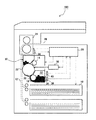
以下、本発明の実施形態を、図面に従って説明する。図1には、本実施形態の画像形成装置100の概略構成が示されている。用紙ストッカ10、用紙搬送路12、帯電部14、露光部16、現像部18、感光体ドラム20、転写部22及び定着部24、排紙ストッカ26及び制御部28を含んで構成される。ここでは、電子写真方式のプリンタを例に説明を行うが、本発明は、この方式の画像形成を行う他の装置、例えば複写機にも適用可能である。
Hereinafter, embodiments of the present invention will be described with reference to the drawings. FIG. 1 shows a schematic configuration of an
用紙ストッカ10に準備された用紙(印刷媒体)は、用紙搬送路12に沿って排紙ストッカ26へ向けて搬送される。帯電部14は、感光体ドラム20の表面を帯電させる。制御部28は、外部装置より受け取った原稿画像データに従って露光部16を制御し、帯電した感光体ドラム20上に潜像を形成する。感光体ドラム20の表面に形成された潜像は、現像部18においてトナーが付着されて現像される。転写部22では、感光体ドラム20の表面のトナーが用紙搬送路12に沿って搬送されてきた用紙に転写される。定着部24では、用紙に転写されたトナーが加熱によって定着される。これらの工程により、原稿画像データが用紙上に画像形成され、用紙が排紙ストッカ26に排出される。
The paper (printing medium) prepared in the
画像形成装置100においては、帯電部14、現像部18および感光体ドラム20は、画像形成装置100本体に対し着脱可能なユニットとしてのカートリッジ30に収められている。カートリッジ30に収められた現像部18は、トナーを蓄えるカートリッジと一体化されたトナーボトル32を含む。
In the
カートリッジ30には、記録装置として非接触ICタグ34が取り付けられている。非接触ICタグ34は、マイコン、半導体メモリ、共振回路及びアンテナを内蔵している。非接触ICタグ34の半導体メモリには、タグ自体に特有な識別子、トナー残量、カートリッジ30の新品・中古の違いを示す情報、カートリッジ30の累積使用時間、カートリッジ30の累積使用枚数、カートリッジ30の使用期間等の情報が格納及び保持されている。
A
画像形成装置100には、カートリッジ30が装着されたときの非接触ICタグ34に対向する位置にリーダライタ36が配置される。リーダライタ36は、非接触ICタグ34と電磁気的に相互作用することによって情報をやり取りする。カートリッジ30が装着されている場合、制御部28は、リーダライタ36を介してそのカートリッジ30の非接触ICタグ34から情報を読み出す処理、及び、非接触ICタグ34のメモリへ情報を書き込む処理を行う。
In the
非接触ICタグ34は、カートリッジ30が画像形成装置100に装着された際に発熱源となる定着部24から離れた位置に取り付けることが好適である。後述するように、発熱源である定着部24の近傍は、結露を生じやすく、ここに非接触ICタグ34を配置すると、結露した水分の影響でリーダライタ36との通信が阻害される場合がある。本実施形態では、定着部24から離れた現像部18の近傍に非接触ICタグ34を配置することにより、発熱源から離れた位置に非接触ICタグ34を取り付けることによって結露の影響を小さくしている。
The
また、定着部24の近傍には、温度センサ38が設けられる。一般的に、定着部24には定着部の温度を制御するための温度センサが設けられているのでそれを温度センサ38として流用してもよい。温度センサ38は、定着部24の近傍の温度を検出する。温度センサ38で検出された温度情報は制御部28へ送信される。制御部28は、温度センサ38で検出された温度に基づいて画像形成装置100を制御することができる。
A
画像形成装置においては、使用によって発熱する部分を有している。例えば、本実施形態のように電子写真方式を採用する画像形成装置の場合、用紙等の印刷媒体上に転写されたトナーを加熱、加圧して定着する定着部を有している。よって、定着部は発熱源となる。このような発熱源による温度上昇は、画像形成装置内の他の部分に結露を生じさせることがある。 The image forming apparatus has a portion that generates heat when used. For example, in the case of an image forming apparatus that employs an electrophotographic system as in this embodiment, the image forming apparatus has a fixing unit that fixes toner by heating and pressurizing toner transferred onto a printing medium such as paper. Therefore, the fixing unit becomes a heat generation source. Such a temperature rise due to the heat source may cause condensation in other parts of the image forming apparatus.
一方、定着部は、上述のように、トナーを加熱、加圧して用紙上に定着するものであり、トナーが転写された後、なるべく速やかに定着を行うことが望ましい。このために、転写部と定着部は近接されて設けられる。また、潜像を現像後、速やかに転写を行うことが好ましく、転写部と現像部も近接して配置される。しかし、前述のように定着部は発熱源であり、この近傍に配置される転写部および現像部は定着部の温度上昇の影響を受け、現像部、定着部に係る構成要素、具体的には感光体ドラム20やトナーボトル32に結露が生じる場合がある。結露が生じたまま動作すると、画質の劣化や装置の故障を招くことになる。本実施形態の画像形成装置100においては、結露が発生すると推定される条件(以下結露条件と記す。)をあらかじめ定めておき、この結露条件が満足されると画像形成動作を停止し、一方で、結露条件となったことを非接触ICタグ34のメモリに書き込む。この結露に係る制御について、以下説明する。
On the other hand, as described above, the fixing unit heats and pressurizes the toner and fixes it on the paper, and it is desirable to fix the toner as soon as possible after the toner is transferred. For this purpose, the transfer portion and the fixing portion are provided close to each other. Moreover, it is preferable to transfer the latent image immediately after development, and the transfer portion and the developing portion are also arranged close to each other. However, as described above, the fixing unit is a heat source, and the transfer unit and the developing unit arranged in the vicinity thereof are affected by the temperature rise of the fixing unit, and the components related to the developing unit and the fixing unit, specifically, Condensation may occur on the
結露が発生するのは、発熱源である定着部24の温度が急激に上昇するときであり、具体的には、画像形成装置100の電源を投入し起動するときである。また、画像形成装置100が電源を入れているにもかかわらず長時間使用されず、定着部24等の加熱を行っていない状態、いわゆる省電力モードから復帰させる場合にも同様に急激な昇温が生じる。この急激な昇温が生じる動作が開始された時点で、結露の発生に対応した制御が開始される。
Condensation occurs when the temperature of the fixing
図2には、結露の発生に対応するためのフローチャートが示されている。電源投入など、定着部24等の昇温が開始される状況になったら、温度センサ38により昇温前の定着部周辺の温度を検出する(S100)。この初期温度に基づき、結露が生じる条件(結露条件)を満足しているかを判断する(S102)。結露条件は、あらかじめ実験的に求めておくことができる。条件の具体的な例としては、初期温度が10℃以下であったとき、または定着部24の加熱目標温度と初期温度の差が100℃以上となっているときなどとできる。
FIG. 2 shows a flowchart for dealing with the occurrence of condensation. When the temperature of the fixing
結露条件を満足していた場合、結露が発生した旨の情報およびその時の時刻を非接触ICタグ34に書き込む(S104)。そして、画像形成装置100を結露モードに設定する(S106)。結露モードは、所定時間、当該装置の画像形成動作を停止するモードであり、所定時間経過後、通常動作に復帰する。なお、結露条件は、必ず結露が発生する条件ではなく、結露が発生する可能性がある条件である。結露モード設定後、定着部24の昇温を開始する(S108)。結露モードにより一定期間、画像形成動作が禁止されるが、その間に定着部等の昇温を行い、結露モードが解除となったとき直ちに画像形成動作を行えるように準備する。また、結露モードにおいては、一定時間が経過するなど、結露が解消したと考えられる時点で、自動的に画像形成動作が再開される。自動的に動作が再開されるので、操作者が画像形成動作ができるようになるまで、当該装置の近傍で待つ必要がなくなる。また、結露モードから通常動作に復帰すると、非接触ICタグ34の結露に係る情報は取り消される。
If the dew condensation condition is satisfied, information indicating that dew condensation has occurred and the time at that time are written in the non-contact IC tag 34 (S104). Then, the
一方、ステップS102で結露条件が満足されていない場合、非接触ICタグ34の情報を読み出し(S110)、読み出した情報に結露発生履歴があるかが判断される(S112)。履歴があった場合、さらに非接触ICタグ34に記録されている結露条件を満足していると判断した時刻を読み出し、現在の時刻と比較して、経過時間を算出し、この経過時間が所定時間内であるかを判断する(S114)。所定時間内であれば、結露が解消していないと判断し、ステップS106に移行し、結露モードに設定する。また、ステップS112で結露発生履歴がないとされた場合、およびステップS114で、すでに所定時間が経過しているとされた場合は、通常動作に従い、定着部24等の発熱部の昇温を開始する(S108)。なお、昇温開始は、結露により非接触ICタグ34との通信ができなくなる可能性があることを考慮し、非接触ICタグ34への情報の書き込み、またタグからの読み出しが終了してから開始することが好ましい。もちろん、発熱部の昇温による影響が少ない位置にタグが配置されているのであれば、電源投入後直ちに昇温開始することもできる。
On the other hand, if the dew condensation condition is not satisfied in step S102, the information of the
ステップS114において、結露発生が判断されてからの経過時間と比較される所定時間は、結露の程度によって変更してもよい。結露の程度は、例えば、初期温度が低いほど多くなると考えられるから、初期温度が低いときには、長い時間動作が禁止されるようにする。このようにするためには、結露モードにおいて、初期温度を考慮して動作禁止時間を決定すると共に、非接触ICタグ34にも初期温度を書き込んでおく。そして、このタグから読み出した情報に基づき、結露モードを設定するとき、書き込まれた初期温度を考慮して動作禁止時間を決定する。
In step S114, the predetermined time compared with the elapsed time since the occurrence of dew condensation may be changed depending on the degree of dew condensation. For example, the degree of condensation is considered to increase as the initial temperature is lower. Therefore, when the initial temperature is low, the operation is prohibited for a long time. In order to do this, in the dew condensation mode, the operation prohibition time is determined in consideration of the initial temperature, and the initial temperature is also written in the
非接触ICタグ34に結露発生履歴を書き込むことで、結露モードとなった後、画像形成装置100の電源を切り、すぐに再投入した場合であっても、この情報を読み出すことで、再度結露モードを設定することができる。つまり、電源を再投入したとき、定着部周辺の温度が高くなって結露発生条件を満足しなくなっているような場合であっても、電源再投入以前に発生した結露が解消していないと考えられるときには、結露モードを設定することができる。これにより、結露による画像品質の低下や、装置の故障を防止することができる。
Even if the
このような、同一装置内の電源再投入による品質の低下等の対応については、必ずしもカートリッジ30に備えられた非接触ICタグ34のメモリを用いる必要はなく、装置本体に備えられたメモリを用いることもできる。しかし、結露モードが設定された画像形成装置100から、カートリッジ30を取り出して、他の装置にこれを装着した場合には、元の装置に備えられたメモリに結露発生の履歴を記憶しても役に立たない。つまり、付け替えた側の新たな装置において、結露条件が満足していなければ、カートリッジ30内に結露が発生していても、結露モードが設定されずに、画像形成動作が実行されてしまう。本実施形態の画像形成装置100において、カートリッジに配置された非接触ICタグ34に、結露発生履歴を書き込む意義はここにある。すなわち、カートリッジ30を新たに取り付けた装置において、このカートリッジ30の非接触ICタグ34から読み出した情報により、結露モードが設定できることで、結露が発生しているカートリッジの使用を確実に防止することができる。
In order to cope with such a decrease in quality due to re-powering in the same apparatus, it is not always necessary to use the memory of the
結露発生条件について、上述の実施形態においては、昇温前に検出した温度に基づいたものであったが、昇温の前後の温度を用いたものとすることもできる。例えば、昇温前の初期温度と、昇温前後の温度差に基づき結露条件を設定することができる。具体的には、初期温度が10℃以下であり、昇温前後の温度差が100℃以上であったときに結露が生じると判断することができる。 Condensation generation conditions are based on the temperature detected before the temperature increase in the above-described embodiment, but the temperatures before and after the temperature increase can also be used. For example, the dew condensation condition can be set based on the initial temperature before the temperature rise and the temperature difference before and after the temperature rise. Specifically, it can be determined that condensation occurs when the initial temperature is 10 ° C. or less and the temperature difference between before and after the temperature rise is 100 ° C. or more.
また、装置内、特にカートリッジ30の周辺に湿度センサ40を設け、温度と湿度に基づき結露条件を設定することもできる。
It is also possible to provide a
本実施形態の着脱可能なユニットは、感光体ドラム20とトナーボトル32の両者を含むカートリッジ30であったが、いずれか一方を含むユニットの場合であっても本発明を適用することができる。また、感光体部材としてドラムを備えた装置を例として示したが、感光体部材は、ベルト等の他の形態であっても良い。
The detachable unit of the present embodiment is the
12 用紙搬送路、14 帯電部、16 露光部、18 現像部、20 感光体ドラム、22 転写部、24 定着部、28 制御部、30 カートリッジ、32 トナーボトル、34 非接触ICタグ、36 リーダライタ、38 温度センサ、40 湿度センサ、100 画像形成装置。
12 Paper transport path, 14 Charging unit, 16 Exposure unit, 18 Development unit, 20 Photosensitive drum, 22 Transfer unit, 24 Fixing unit, 28 Control unit, 30 Cartridge, 32 Toner bottle, 34 Non-contact IC tag, 36 Reader /
Claims (11)
結露により動作に影響を受ける構成要素を含み、装置本体に対し着脱可能なユニットと、
を有する画像形成装置であって、
前記着脱可能なユニットに備えられた記憶手段と、
装置内の温度および湿度の少なくとも一方を検出する装置内環境検出手段と、
装置内環境検出手段の検出結果に基づき、前記構成要素に結露が生じる条件である結露条件を満たしているか判断する結露条件判断手段と、
結露条件判断手段が結露条件を満たしていると判断したとき、その旨の情報を前記記録手段に書き込む書き込み手段と、
を有する画像形成装置。 The device body;
A unit that includes components that are affected by operation due to condensation, and is detachable from the main unit;
An image forming apparatus having
Storage means provided in the removable unit;
In-device environment detection means for detecting at least one of temperature and humidity in the device;
Based on the detection result of the in-device environment detection means, the condensation condition determination means for determining whether or not the condensation condition, which is a condition for causing condensation on the component, is satisfied,
When the dew condensation condition determining means determines that the dew condensation condition is satisfied, writing means for writing information to that effect in the recording means;
An image forming apparatus.
前記記憶手段に記憶された情報を読み出す読み出し手段と、
読み出し手段により読み出された情報に、結露条件を満たしている旨の情報が含まれるとき、当該装置の画像形成動作を停止させる停止手段と、
を有する画像形成装置。 The image forming apparatus according to claim 1,
Reading means for reading information stored in the storage means;
Stop means for stopping the image forming operation of the apparatus when the information read by the reading means includes information indicating that the dew condensation condition is satisfied;
An image forming apparatus.
前記書き込み手段は、結露条件を満たしていると判断されたときの時刻を、前記記憶手段に書き込む、
画像形成装置。 The image forming apparatus according to claim 1,
The writing means writes the time when it is determined that the dew condensation condition is satisfied, to the storage means;
Image forming apparatus.
前記記憶手段に記憶された情報を読み出す読み出し手段と、
読み出し手段により読み出された情報に、結露条件を満たしている旨の情報が含まれ、かつ読み出された前記判断されたときの時刻からの経過時間が所定時間以内であるとき、当該装置の画像形成動作を停止させる停止手段と、
を有する画像形成装置。 The image forming apparatus according to claim 3, wherein
Reading means for reading information stored in the storage means;
When the information read by the reading means includes information indicating that the dew condensation condition is satisfied, and the elapsed time from the time when the reading is performed is within a predetermined time, Stop means for stopping the image forming operation;
An image forming apparatus.
結露により動作に影響を受ける構成要素を含み、装置本体に対し着脱可能なユニットと、
を有する画像形成装置であって、
前記着脱可能なユニットに備えられた記憶手段と、
前記記憶手段に記憶された情報を読み出す読み出し手段と、
読み出し手段により読み出された情報に、前記構成要素に結露が生じる条件である結露条件を満たしている旨の情報が含まれるとき、当該装置の画像形成動作を停止させる停止手段と、
を有する、画像形成装置。 The device body;
A unit that includes components that are affected by operation due to condensation, and is detachable from the main unit;
An image forming apparatus having
Storage means provided in the removable unit;
Reading means for reading information stored in the storage means;
When the information read by the reading unit includes information indicating that a dew condensation condition, which is a condition for causing dew condensation on the component, is included, a stop unit that stops the image forming operation of the apparatus;
An image forming apparatus.
結露により動作に影響を受ける構成要素を含み、装置本体に対し着脱可能であり、記憶手段を備えるユニットと、
を有する画像形成装置の制御方法であって、
装置内の温度および湿度の少なくとも一方を検出するステップと、
検出された温度および湿度の少なくとも一方に基づき、前記構成要素に結露が生じる条件である結露条件を満たしているかを判断するステップと、
結露条件を満たしていると判断されたとき、その旨の情報を前記記録手段に書き込むステップと、
を有する画像形成装置の制御方法。 The device body;
A unit that includes components that are affected by operation due to condensation, is detachable from the apparatus main body, and includes a storage unit;
An image forming apparatus control method comprising:
Detecting at least one of temperature and humidity in the device;
Determining whether or not a condensation condition, which is a condition for causing condensation on the component, is satisfied based on at least one of the detected temperature and humidity;
When it is determined that the condensation condition is satisfied, writing information to that effect in the recording means;
A method for controlling an image forming apparatus.
前記記憶手段に記憶された情報を読み出すステップと、
読み出された情報に、結露条件を満たしている旨の情報が含まれるとき、当該装置の画像形成動作を停止させるステップと、
を有する画像形成装置の制御方法。 A method for controlling an image forming apparatus according to claim 9, comprising:
Reading information stored in the storage means;
A step of stopping the image forming operation of the apparatus when the read information includes information indicating that the dew condensation condition is satisfied;
A method for controlling an image forming apparatus.
結露により動作に影響を受ける構成要素を含み、装置本体に対し着脱可能であり、記憶手段を備えるユニットと、
を有する画像形成装置の制御方法であって、
前記記憶手段に記憶された情報を読み出すステップと、
読み出された情報に、前記構成要素に結露が生じる条件である結露条件を満たしている旨の情報が含まれるとき、当該装置の画像形成動作を停止させるステップと、
を有する画像形成装置の制御方法。 The device body;
A unit that includes components that are affected by operation due to condensation, is detachable from the apparatus main body, and includes a storage unit;
An image forming apparatus control method comprising:
Reading information stored in the storage means;
A step of stopping the image forming operation of the apparatus when the read information includes information indicating that a dew condensation condition that is a condition for causing dew condensation on the component is satisfied;
A method for controlling an image forming apparatus.
Priority Applications (1)
| Application Number | Priority Date | Filing Date | Title |
|---|---|---|---|
| JP2006127532A JP2007298819A (en) | 2006-05-01 | 2006-05-01 | Image forming apparatus, and method of controlling image forming apparatus |
Applications Claiming Priority (1)
| Application Number | Priority Date | Filing Date | Title |
|---|---|---|---|
| JP2006127532A JP2007298819A (en) | 2006-05-01 | 2006-05-01 | Image forming apparatus, and method of controlling image forming apparatus |
Publications (2)
| Publication Number | Publication Date |
|---|---|
| JP2007298819A true JP2007298819A (en) | 2007-11-15 |
| JP2007298819A5 JP2007298819A5 (en) | 2009-06-18 |
Family
ID=38768344
Family Applications (1)
| Application Number | Title | Priority Date | Filing Date |
|---|---|---|---|
| JP2006127532A Withdrawn JP2007298819A (en) | 2006-05-01 | 2006-05-01 | Image forming apparatus, and method of controlling image forming apparatus |
Country Status (1)
| Country | Link |
|---|---|
| JP (1) | JP2007298819A (en) |
Cited By (2)
| Publication number | Priority date | Publication date | Assignee | Title |
|---|---|---|---|---|
| JP2019211644A (en) * | 2018-06-05 | 2019-12-12 | キヤノン株式会社 | Image forming apparatus and control method for the same |
| JP2019219504A (en) * | 2018-06-19 | 2019-12-26 | 株式会社リコー | Image forming apparatus and control method |
-
2006
- 2006-05-01 JP JP2006127532A patent/JP2007298819A/en not_active Withdrawn
Cited By (3)
| Publication number | Priority date | Publication date | Assignee | Title |
|---|---|---|---|---|
| JP2019211644A (en) * | 2018-06-05 | 2019-12-12 | キヤノン株式会社 | Image forming apparatus and control method for the same |
| JP2019219504A (en) * | 2018-06-19 | 2019-12-26 | 株式会社リコー | Image forming apparatus and control method |
| JP7087710B2 (en) | 2018-06-19 | 2022-06-21 | 株式会社リコー | Image forming device and control method |
Similar Documents
| Publication | Publication Date | Title |
|---|---|---|
| KR102169264B1 (en) | Image forming apparatus, cartridge management method, and storage medium | |
| US20170230540A1 (en) | Image forming apparatus, control method thereof, storage medium, and cartridge | |
| JP4679009B2 (en) | Image forming apparatus | |
| JP4871706B2 (en) | Image forming apparatus | |
| JP2002169431A (en) | Image forming device, replacement parts and ic chip used in image forming device | |
| JP2007298819A (en) | Image forming apparatus, and method of controlling image forming apparatus | |
| US9921534B2 (en) | Image forming apparatus | |
| JP2009020284A (en) | Image forming apparatus | |
| JP2010078953A (en) | Image forming apparatus | |
| KR100727928B1 (en) | Fuser, an image forming apparatus having the same, and a fuser control method | |
| US20020030845A1 (en) | Image forming apparatus and control method therefor | |
| JP2009229825A (en) | Image forming device | |
| JP2010224351A (en) | Image forming apparatus | |
| JP2005345564A (en) | Image forming apparatus | |
| JP2008139615A (en) | Image forming apparatus | |
| JP2007057879A (en) | Image forming apparatus and control method of image forming apparatus | |
| US9239975B2 (en) | Image forming apparatus performing a delay process when a number of sheets printed in a unit of time is equal to or greater than a reference number | |
| JP2016004082A (en) | Image forming apparatus and control method thereof | |
| JP5408854B2 (en) | Image forming apparatus | |
| JP2008158083A (en) | Image forming apparatus | |
| JP5352166B2 (en) | Image forming apparatus | |
| JP2019030986A (en) | Image formation apparatus, control method for image formation apparatus, and program | |
| JP6835012B2 (en) | Image forming device | |
| JP2008107650A (en) | Image forming apparatus, control method for image forming apparatus and control program for image forming apparatus | |
| JP5074832B2 (en) | Developing device and image forming apparatus |
Legal Events
| Date | Code | Title | Description |
|---|---|---|---|
| A521 | Written amendment |
Free format text: JAPANESE INTERMEDIATE CODE: A523 Effective date: 20090430 |
|
| A621 | Written request for application examination |
Free format text: JAPANESE INTERMEDIATE CODE: A621 Effective date: 20090430 |
|
| A761 | Written withdrawal of application |
Free format text: JAPANESE INTERMEDIATE CODE: A761 Effective date: 20100311 |