JP2007296522A - Method and apparatus for maintaining inkjet print head using parking structure with spray mechanism - Google Patents
Method and apparatus for maintaining inkjet print head using parking structure with spray mechanism Download PDFInfo
- Publication number
- JP2007296522A JP2007296522A JP2007120511A JP2007120511A JP2007296522A JP 2007296522 A JP2007296522 A JP 2007296522A JP 2007120511 A JP2007120511 A JP 2007120511A JP 2007120511 A JP2007120511 A JP 2007120511A JP 2007296522 A JP2007296522 A JP 2007296522A
- Authority
- JP
- Japan
- Prior art keywords
- print head
- solvent
- standby
- nozzle plate
- spray
- Prior art date
- Legal status (The legal status is an assumption and is not a legal conclusion. Google has not performed a legal analysis and makes no representation as to the accuracy of the status listed.)
- Pending
Links
Images


Classifications
-
- B—PERFORMING OPERATIONS; TRANSPORTING
- B41—PRINTING; LINING MACHINES; TYPEWRITERS; STAMPS
- B41J—TYPEWRITERS; SELECTIVE PRINTING MECHANISMS, i.e. MECHANISMS PRINTING OTHERWISE THAN FROM A FORME; CORRECTION OF TYPOGRAPHICAL ERRORS
- B41J2/00—Typewriters or selective printing mechanisms characterised by the printing or marking process for which they are designed
- B41J2/005—Typewriters or selective printing mechanisms characterised by the printing or marking process for which they are designed characterised by bringing liquid or particles selectively into contact with a printing material
- B41J2/01—Ink jet
- B41J2/135—Nozzles
- B41J2/165—Preventing or detecting of nozzle clogging, e.g. cleaning, capping or moistening for nozzles
- B41J2/16517—Cleaning of print head nozzles
- B41J2/1652—Cleaning of print head nozzles by driving a fluid through the nozzles to the outside thereof, e.g. by applying pressure to the inside or vacuum at the outside of the print head
-
- B—PERFORMING OPERATIONS; TRANSPORTING
- B05—SPRAYING OR ATOMISING IN GENERAL; APPLYING FLUENT MATERIALS TO SURFACES, IN GENERAL
- B05C—APPARATUS FOR APPLYING FLUENT MATERIALS TO SURFACES, IN GENERAL
- B05C11/00—Component parts, details or accessories not specifically provided for in groups B05C1/00 - B05C9/00
- B05C11/10—Storage, supply or control of liquid or other fluent material; Recovery of excess liquid or other fluent material
-
- B—PERFORMING OPERATIONS; TRANSPORTING
- B41—PRINTING; LINING MACHINES; TYPEWRITERS; STAMPS
- B41J—TYPEWRITERS; SELECTIVE PRINTING MECHANISMS, i.e. MECHANISMS PRINTING OTHERWISE THAN FROM A FORME; CORRECTION OF TYPOGRAPHICAL ERRORS
- B41J2/00—Typewriters or selective printing mechanisms characterised by the printing or marking process for which they are designed
- B41J2/005—Typewriters or selective printing mechanisms characterised by the printing or marking process for which they are designed characterised by bringing liquid or particles selectively into contact with a printing material
- B41J2/01—Ink jet
- B41J2/015—Ink jet characterised by the jet generation process
- B41J2/04—Ink jet characterised by the jet generation process generating single droplets or particles on demand
- B41J2/045—Ink jet characterised by the jet generation process generating single droplets or particles on demand by pressure, e.g. electromechanical transducers
- B41J2/04501—Control methods or devices therefor, e.g. driver circuits, control circuits
- B41J2/04541—Specific driving circuit
-
- B—PERFORMING OPERATIONS; TRANSPORTING
- B41—PRINTING; LINING MACHINES; TYPEWRITERS; STAMPS
- B41J—TYPEWRITERS; SELECTIVE PRINTING MECHANISMS, i.e. MECHANISMS PRINTING OTHERWISE THAN FROM A FORME; CORRECTION OF TYPOGRAPHICAL ERRORS
- B41J2/00—Typewriters or selective printing mechanisms characterised by the printing or marking process for which they are designed
- B41J2/005—Typewriters or selective printing mechanisms characterised by the printing or marking process for which they are designed characterised by bringing liquid or particles selectively into contact with a printing material
- B41J2/01—Ink jet
- B41J2/17—Ink jet characterised by ink handling
- B41J2/175—Ink supply systems ; Circuit parts therefor
Abstract
Description
本出願は、2006年7月26日出願の米国特許出願第11/493310号「噴霧機構を備えた待機構造体を用いたインクジェット印刷ヘッドの保守方法及び装置」(代理人整理番号11334、現在10648)、2006年4月29日出願の米国特許仮出願第60/795709号「待機構造体を用いたインクジェット印刷ヘッドの保守方法及び装置」(代理人整理番号10648/L)、及び2006年4月29日出願の米国特許仮出願第60/796297号「インクジェット印刷システムの操作方法及び装置」(代理人整理番号10647/L)に基づく優先権を主張し、これらは引用により全て本願に組み込まれる。 No. 11/493310, filed Jul. 26, 2006 “Inkjet printhead maintenance method and apparatus using standby structure with spray mechanism” (Attorney Docket No. 11334, currently 10648). ), US Provisional Patent Application No. 60/795709, filed Apr. 29, 2006, “Maintenance Method and Apparatus for Inkjet Printhead Using Standby Structure” (Attorney Docket No. 10648 / L), and April 2006 Claimed priority based on US Provisional Application No. 60 / 79,297, “Method and apparatus for operating inkjet printing system” (Attorney Docket No. 10647 / L), filed 29 days, all incorporated herein by reference.
本出願は、2005年2月18日出願の米国特許出願第11/061148号「ディスプレイ用カラーフィルタのインクジェット印刷方法及び装置」(代理人整理番号9521−5)、2004年11月4日出願の米国特許仮出願第60/625550号「インクジェット法によるフラットパネルディスプレイのカラーフィルタの製造装置及び方法」(代理人整理番号9521/L)、2005年9月29日出願の米国特許出願第11/238631号「インクジェット印刷ヘッドの洗浄方法及び装置」(代理人整理番号9838)、及び2005年9月27日出願の米国特許仮出願第60/721340号「インクジェット送出モジュール」(代理人整理番号10145/L)に関連し、それぞれ引用により全て本願に組み込まれる。 This application is filed on US patent application Ser. No. 11/061148, “Inkjet printing method and apparatus for color filter for display” (Attorney Docket No. 9521-5), filed on Nov. 4, 2004. U.S. Provisional Patent Application No. 60/625550 "Apparatus and Method for Manufacturing Color Filter for Flat Panel Display by Inkjet Method" (Attorney Docket No. 9521 / L), U.S. Patent Application No. No. “Inkjet printhead cleaning method and apparatus” (Attorney Docket No. 9838) and US Provisional Patent Application No. 60/721340, filed September 27, 2005 “Inkjet Delivery Module” (Attorney Docket No. 10145 / L Each of which is incorporated herein by reference.
本発明は概してフラットパネルディスプレイ製造中に用いるインクジェット印刷システムに関連し、特にはインクジェット印刷ヘッドを保守するための装置及び方法に関連する。 The present invention relates generally to ink jet printing systems used during flat panel display manufacturing, and more particularly to an apparatus and method for maintaining an ink jet print head.
フラットパネルディスプレイ産業は、ディスプレイ装置、特にカラーフィルタを製造するためにインクジェット印刷を用いようと試みてきた。しかしながら、インクジェット印刷で使用するインクジェット印刷ヘッドはインクで塞がれたり、目詰まりや被膜の形成により、あるいは別の理由でインクジェット印刷法での使用に不適当な状態となる場合がある。インクジェット印刷ヘッドの従来の洗浄方法は手作業でのふき取り作業を必要とする。この方法はインクジェット印刷ヘッドをオフラインにして清浄な製造環境から離すことを含む場合が多く、時間がかかり、印刷ヘッドを損傷したり所要の印刷位置から印刷ヘッドがずれる可能性がある。従って、インクジェット印刷ヘッドを保守するための改善された方法及び装置が求められている。 The flat panel display industry has attempted to use inkjet printing to manufacture display devices, particularly color filters. However, ink jet print heads used in ink jet printing may become unsuitable for use in ink jet printing methods due to clogging with ink, clogging, film formation, or for other reasons. Conventional cleaning methods for inkjet printheads require manual wiping. This method often involves taking the ink jet print head off line and away from a clean manufacturing environment, which is time consuming and can damage the print head or cause the print head to deviate from the required print position. Accordingly, there is a need for an improved method and apparatus for maintaining an inkjet printhead.
本発明の特定の態様において、印刷ヘッド待機構造体は噴霧装置を含む筺体と、筺体に隣接し、印刷ヘッドを受け止めると筺体内において印刷ヘッドが噴霧装置に露出されるように構成した待機場所とを含む。 In a particular aspect of the invention, the print head standby structure includes a housing that includes a spray device, and a standby location that is configured to be adjacent to the housing and exposed to the spray device within the housing upon receipt of the print head. including.
本発明の別の態様においては、印刷ヘッドを待機構造体内に密閉し、印刷ヘッドのその他の部分に飛散させることなく溶剤を印刷ヘッドのノズルプレートに噴霧することを含む方法を提供する。 In another aspect of the present invention, a method is provided that includes sealing a print head within a standby structure and spraying a solvent onto a nozzle plate of the print head without splashing to other portions of the print head.
本発明のさらに別の態様においては、フラットパネルディスプイ用のカラーフィルタ製造用に適合され、それぞれがノズルプレートを備えた複数の印刷ヘッドを含むインクジェットプリンタと、噴霧装置と、印刷ヘッドを受け止めるとその内部で受け止めた印刷ヘッドが噴霧器に露出されるよう構成した待機場所とを有する筺体とを含む印刷ヘッド待機構造体とを含むシステムが提供される。 In yet another aspect of the invention, an ink jet printer adapted for manufacturing a color filter for a flat panel display, each including a plurality of print heads with nozzle plates, a spraying device, and receiving the print head There is provided a system including a printhead standby structure including a housing having a standby location configured to expose a printhead received therein to the sprayer.
本発明のその他の特徴と態様は以下の詳細な説明、特許請求の範囲、ならびに添付図面によりさらに十分に明確となる。 Other features and aspects of the present invention will become more fully apparent from the following detailed description, the appended claims and the accompanying drawings.
フラットパネルディスプレイ用カラーフィルタの製造で使用するインクジェット印刷ヘッドのノズルは目詰まりしたり、そうでないとしても印刷ヘッド上や内部でのインクの乾きにより流れが妨げられる場合がある。様々なノズル保守・パージ法を用いて乾燥したインクを除去することが可能だが、印刷ヘッド上で乾燥するインクの除去又はその量を低減するための方法では、ノズルに溶剤及び/又は印刷ヘッドに表面処理剤を適用する噴霧器を含む印刷ヘッド待機構造体を使用することができる。 Ink jet print head nozzles used in the manufacture of color filters for flat panel displays may be clogged or otherwise impeded by ink drying on or inside the print head. Various nozzle maintenance and purge methods can be used to remove the dried ink, but methods to remove or reduce the amount of ink that dries on the printhead include a solvent on the nozzle and / or a printhead. A printhead standby structure that includes a sprayer to apply the surface treatment agent can be used.
別の保守技法においては、印刷ヘッドをある期間にわたって溶剤浴に供する。この技法は当該技術分野で進歩的であることが立証されているが、場合によっては、除去、吸収される大量のインクにより溶剤浴が汚染される可能性がある。汚染された溶剤は印刷ヘッドノズル上で乾燥又は付着するため、このような状況において、溶剤浴は解決を意図していた問題を再導入してしまう。本発明の発明者は、噴霧のみ、又は溶剤浴後に噴霧を行うことによりこの問題が回避できるという結論に至った。 In another maintenance technique, the print head is subjected to a solvent bath for a period of time. While this technique has proven to be progressive in the art, in some cases the solvent bath can be contaminated by the large amount of ink removed and absorbed. In this situation, the solvent bath reintroduces the problem that was intended to be solved because contaminated solvent dries or deposits on the printhead nozzles. The inventors of the present invention have come to the conclusion that this problem can be avoided by spraying only, or by spraying after a solvent bath.
作動中、基板を印刷した後、1回以上の印刷パス後、及び/又は印刷ヘッド上での乾燥や目詰まりを防止するに十分な頻度で、印刷ヘッドを印刷ヘッド待機構造体へと戻す。印刷ヘッド待機構造体内に一旦戻すと、印刷ヘッド(又はその一部)の表面に溶剤を噴霧して、表面状態を保守する。噴霧された溶剤は溶解したインクと共に印刷ヘッドから滴下し、浴容器内に溜まる。あるいは、印刷ヘッドを溶剤浴中まで降下させ、溶剤浴を排液し(又は印刷ヘッドを汚染溶剤上方まで引き上げる)、その後、新しい溶剤を印刷ヘッドに噴霧する。 In operation, after printing the substrate, after one or more printing passes, and / or frequently enough to prevent drying and clogging on the printhead, the printhead is returned to the printhead standby structure. Once returned to the printhead standby structure, solvent is sprayed onto the surface of the printhead (or part thereof) to maintain the surface condition. The sprayed solvent is dripped from the print head together with the dissolved ink, and accumulates in the bath container. Alternatively, the print head is lowered into the solvent bath, the solvent bath is drained (or the print head is pulled up above the contaminating solvent), and then new solvent is sprayed onto the print head.
実施形態によっては、1つ以上の噴霧器が、広範囲にわたる印刷ヘッドのノズルプレート表面をカバーする溶剤を送り出す。1つ以上の噴霧器は、その噴霧範囲を広げかつ溶剤を様々な角度から適用して汚染物質を緩めるために可動式であってもよい。印刷ヘッドそれ自体を、浴容器に溶剤を噴射してノズル内のインクを全て排出するよう構成してもよい。あるいは又はそれに加えて、印刷ヘッド待機構造体は、印刷ヘッドを印刷に再使用する前に、例えば清浄な乾燥した空気(Clean dry air:CDA)を適用して印刷ヘッドから余分な溶媒を除去するための別のノズルを含んでいてもよい。 In some embodiments, one or more atomizers deliver solvent that covers a wide range of printhead nozzle plate surfaces. One or more nebulizers may be movable to widen their spray range and apply solvent from various angles to loosen contaminants. The print head itself may be configured to eject all of the ink in the nozzles by jetting solvent into the bath container. Alternatively or in addition, the printhead standby structure may remove excess solvent from the printhead, for example, by applying clean dry air (CDA) before the printhead is reused for printing. Another nozzle may be included.
実施形態によっては、印刷ヘッド待機構造体を、印刷ヘッド及び/又は印刷ヘッドのノズルに表面処理剤を適用するために使用する。印刷ヘッド及び/又はノズルの表面には、インクが表面を濡らすことのない(例えば、玉状になる)疎インク性とするために選択した化学薬品又は処理剤を噴霧又はコーティングしてもよい。実施形態によっては、表面処理剤及び溶剤は1つの溶液に混合したものである。実施態様によっては、溶液を印刷ヘッドのノズルプレートに適用し、溶液を浴内に滴下させ、溶液を回収・再利用する。このような実施形態において、溶液は再利用する前にろ過してもよい。 In some embodiments, the printhead standby structure is used to apply a surface treatment to the printhead and / or nozzles of the printhead. The surface of the print head and / or nozzles may be sprayed or coated with a chemical or processing agent selected to make the ink oleophobic so that the ink does not wet the surface (eg, beads). In some embodiments, the surface treatment agent and the solvent are mixed in one solution. In some embodiments, the solution is applied to the nozzle plate of the print head, the solution is dropped into the bath, and the solution is collected and reused. In such embodiments, the solution may be filtered before reuse.
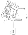
図1は総じて参照番号100で示される本発明のインクジェット印刷システムの一実施形態の正面斜視図である。本発明のインクジェット印刷システム100は、一模範実施形態において、印刷ブリッジ102を含む。印刷ブリッジ102はステージ104上方に位置及び/又は連結されている。ステージ104は基板106を支持する。印刷ブリッジ102上には印刷ヘッド108、110、112が支持されている。印刷ヘッド108、110、112、及び印刷ブリッジ102はシステム制御装置114に(例えば、論理的及び/又は電気的に)連結されている。本発明のインクジェット印刷システム100は、1つ以上の印刷ヘッド待機ステーション116、118、120と1つ以上の印刷ヘッド洗浄ステーション122も含む。
FIG. 1 is a front perspective view of one embodiment of the inkjet printing system of the present invention, indicated generally by the
図1の模範実施形態において、印刷ブリッジ102はインクジェット印刷を促進するような形でステージ104上に支持されている。印刷ブリッジ102及び/又はステージ104は、図1において矢印X、Yで示される正及び負のX、Y方向の双方に可動し得る。同一又は別の実施形態において、印刷ブリッジ102及びステージ104は回転可能であってもよい。印刷ブリッジ102は印刷ヘッド108、110、112及び/又はその他のデバイス(例えば、センサ、画像化システム、レンジファインダ等)を幾つでも支持及び移動可能である。基板106は可動式ステージ104上に設置する、あるいは実施形態によっては連結される。
In the exemplary embodiment of FIG. 1,
図1Aにおいて、印刷ブリッジ102上には3つの印刷ヘッド108、110、112のみが図示されているが、印刷ブリッジ102上にはいくつ印刷ヘッドを搭載及び/又は共に使用してもよいことに留意することが大切である(例えば、1、2、4、5、6、7個等の印刷ヘッド)。印刷ヘッド108、110、112はそれぞれ1色のカラーインクを吐出可能であり、実施形態によっては複数のカラーインクを吐出可能である。インクジェット滴を的確に付着させるために、インクジェット印刷ヘッド108、110、112は、垂直方向、水平方向、及び/又は回転方向に可動及び/又は整列可能であってもよい。印刷ヘッド108〜112を位置決めして的確にインクジェット印刷するために、印刷ブリッジ102も可動式及び/又は回転可能であってもよい。作動中、インクジェット印刷ヘッド108、110、112はインクを液滴状で(例えば、ノズルから)吐出する。
In FIG. 1A, only three
本発明での使用に適した市販の印刷ヘッドの例は、ニューハンプシャー州レバノンのスペクトラ社(Spectra, Inc.)製造のモデルS−128シリーズ、128チャネルジェットアセンブリである。これら特定のジェットアセンブリは2つの電気的に独立した圧電素子薄片を含み、それぞれが64個のアドレス可能なチャネルを有し、あわせて合計128の噴流を供給する。印刷ヘッドは多数のノズルを有するノズルプレートを備え、ノズルは間隔約0.020インチで列状に配置されている。異なるサイズのノズルを備えた別の印刷ヘッドを使用してもよい。ノズルはノズルプレート150にオリフィスを備える、あるいはノズルプレートから延びる、開口部を備えた突出部を備えていてもよい。実施形態によっては、金メッキ又は金コーティングを施した印刷ヘッド/ノズルを用いて、特には疎インク表面処理と共に、印刷ヘッド/ノズルの濡れをより軽減する。濡れ低下により、インク噴射の信頼性と液滴サイズの再現性が改善され、インク噴射性能が改善される。
An example of a commercially available print head suitable for use with the present invention is the Model S-128 series, 128 channel jet assembly manufactured by Spectra, Inc., Lebanon, New Hampshire. These particular jet assemblies include two electrically independent piezoelectric element slices, each having 64 addressable channels, for a total of 128 jets. The print head includes a nozzle plate having a number of nozzles, the nozzles being arranged in rows with a spacing of about 0.020 inches. Different print heads with different sized nozzles may be used. The nozzle may include an orifice in the
実施形態によっては、基板106、印刷ヘッド108、110、112からのインク液滴、及び/又は印刷ヘッド108、110、112のノズルの画像をキャプチャ可能な画像化システム124をインクジェット印刷システム100内に組み込む。そういった画像化システム124は、直径約2umから約100umのインク液滴を識別するに十分な質の画像をキャプチャ可能なように構成してもよい。従って、画像化システム124は望遠ズームレンズを備えていてもよく、また高解像度を有し得る(例えば、少なくとも約1024〜768画素)。その他のカメラ型及び/又は解像度を使用してもよい。画像化システム124は電動/自動照準、ズーム及び/又はフォーカス機能も備えていてもよい。作動中、画像化システム124を用いて印刷ヘッド108、110、112のノズルを点検し、ノズルに洗浄及び/又は疎インク表面処理が必要かどうかを決定してもよい(例えば、ノズル上でインクが蓄積又は乾燥した為、ノズルを通過した新しい溶剤が透明でなくインク色を帯びている、及び/又はインクがノズル/印刷ヘッド表面上で玉状にならなくなった)。
In some embodiments, an
印刷ブリッジ102、ステージ104、及び/又はインクジェット印刷ヘッド108、110、112はシステム制御装置114に連結してもよい。システム制御装置114は、インクジェット印刷作業中に印刷ブリッジ102、ステージ104、及び/又はインクジェット印刷ヘッド108、110、112の動きを制御するよう適合させてもよい。また、システム制御装置114はインクジェット印刷ヘッド108、110、112用の点弧パルス信号を制御してもよい。システム制御装置114は単一の制御装置又は複数の制御装置を備えてもよい。
印刷ヘッド待機ステーション116、118、120をステージ104より低い位置に配置し、それぞれが個々に上昇して独立して印刷ヘッド108、110、112を受け止めるよう構成してもよい。実施形態によっては、システム100は印刷ヘッド108、110、112につき1つの印刷ヘッド待機ステーション116、118、120を備える。補足的あるいは別の実施形態においては、1つの待機ステーション116を複数の印刷ヘッド108、110、112に使用し、あるいは複数の待機ステーション116、118、120を1つの印刷ヘッド108に用いる。例えば、第1待機ステーション116が印刷ヘッド108に溶剤を噴霧、第2待機ステーション118が圧縮空気で印刷ヘッド108を乾燥、第3待機ステーションが疎インク表面処理剤で印刷ヘッドをコーティングするよう構成する。同様に、1つ以上の印刷ヘッド108、110、112に行うその他の保守、洗浄、及び/又は保護機能に加えて上記の3つの機能例全てを単一の待機ステーション116が行うよう構成してもよい。従って、様々な実施形態において、印刷ヘッド108、110、112は待機ステーション116、118、120の機能の実行により補修又は保守され、印刷ヘッド、機能、待機ステーションの数はいずれであってもよい。
The print
1つ以上の印刷ヘッド拭取りステーション122もまた、印刷ヘッド待機ステーション116、118、120と同一又は同様のやり方や位置で配置することができる。上記で本願に組み込んだ米国特許出願第11/238631号は、本発明のインクジェット印刷システム100での使用に適した印刷ヘッド洗浄ステーションの一例の種々の特徴及び態様を詳細に記載している。
One or more
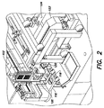
図2は、印刷ヘッド待機構造体116、118、120の3つの実施形態例のうち中央の構造体上方に位置された印刷ヘッド108の拡大斜視図である。図1とは対照的に、印刷ヘッド108が待機構造体のうちの1つである待機構造体118内に待機している状態が図示されている。実施形態によっては、印刷ヘッド待機構造体116、118、120はステージ104の片側に隣接して配置されることに留意する。あるいは又はそれに加え、待機構造体はステージ104の両側、前方、及び/又は後方に配置してもよい。こういった実施形態は、印刷ヘッドが待機構造体に到達するまでの移動に要する時間及び/又は距離を最小限にすると同時に待機構造体の使用を容易にするよう構成される。
FIG. 2 is an enlarged perspective view of the
印刷ヘッド待機構造体116、118、120は、上昇してステージ104と同じ高さ又はそれ以上の高さで印刷ヘッド108、110、112と係合するよう構成してもよい。さらに、ステージ104と同じ高さ又はそれ以下にまで下降させることで、入り込んだ待機構造体116、118、120の上を印刷ヘッド108、110、120が横方向に移動できるクリアランスが形成されるよう構成してもよい。実施形態によっては、待機構造体116、118、120は固定の垂直方向位置を有しており、印刷ヘッド108、110、120は、昇降することで待機構造体116、118、120と係合・離脱するよう構成されている。
The print
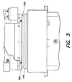
図3は、待機構造体例116に待機させた印刷ヘッド108の正面平面図である。待機構造体116は、ノズルプレート150を含む印刷ヘッド108の下部を受け止めるよう構成された封止部302を含む。封止部302は印刷ヘッド108表面の平坦部と接触するため、印刷ヘッド108の待機中(例えば、パージ工程中)、待機構造体116内で噴霧された溶媒は構造体116内に閉じ込められ、漏れが防止される。封止部302は、待機構造体116が上昇して印刷ヘッド108と係合する又は印刷ヘッド108が待機構造体116内に下降するいずれかの場合に、圧縮されて印刷ヘッド108の表面形状に合致する撓みベローとして構成してもよい。封止部302はあらゆる材料から形成することができ、ゴム、プラスチック、薄板金属、可撓性又は半硬質ポリ塩化ビニル(PVC)、圧縮されて封止部を形成可能であり、またインク、溶剤、印刷ヘッド表面処理剤、及び/又は待機構造体116と共に使用し得るその他の化学物質又は処理と反応しない実用的な材料が含まれる。待機構造体116は、噴霧又はパージ後に構造体中に蓄積され得る溶剤及び/又はインクを除去するための排液路406を備えていてもよい。排液路406は廃棄物処理設備に通じていてもよく、実施形態によっては排液路406は使用済み溶剤/表面処理溶液を溶液リサイクルシステム(図示せず)に戻す。溶液リサイクルシステムは使用済み溶液からインクやその他の汚染物質をろ過し、清浄化した溶液を流体供給槽(図示せず)へと戻す。実施形態によっては、回収した溶液を再使用前にろ過する必要がない。
FIG. 3 is a front plan view of the
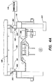
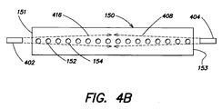
図4Aには、待機構造体例116に待機させた印刷ヘッド108の模範的正面断面図が図示されている。図4Aに図示の待機構造体例116は、印刷ヘッド108の側部に溶剤を飛散させることなく印刷ヘッド108のノズルプレート150上に溶剤及び/又は表面処理化学薬品を噴霧するよう構成した噴霧器402、404を含む。図4Aの具体例には噴霧器402、404の2つしか図示していないが、待機構造体は噴霧器を幾つ備えていてもよく(例えば、1、2、3、4、5、6、7個等)、噴霧器402、404は印刷ヘッド108のノズルに対して様々な配列で位置させることができる。図4に図示の配置において、噴霧器402、404はノズルプレート150の対向する側方端部151、153に近接したその若干下方に位置し、小さい角度広がりで溶剤流を指向するよう形状構成されている。
FIG. 4A illustrates an exemplary front cross-sectional view of the
上述したように、待機構造体116を、垂直方向に移動して印刷ヘッド108と係合・離脱するよう構成してもよい。実施形態によっては、(例えば、空気圧式又は油圧式シリンダのみの、あるいはカム又は昇降回転軸を備えた)アクチュエータ410を用いて待機構造体116を昇降させる。
As described above, the
図4Bは図4Aに図示の待機構造体内にある印刷ヘッドの実施形態例の底部平面図である。図から見て取れるように、そのそれぞれの位置において、各噴霧器402、404は、それが近接するところのノズルプレート表面150の(少なくとも)各半分の噴霧対象域406、408を有する為、ノズルプレート全面が噴霧された溶剤と接触する。実施形態例においては、噴霧器402、404を制御して、溶剤及び/又は表面処理溶液を例えば長さ約6cm×幅0.5cmの領域に全体で流量約5〜20ml/分で供給する。実施形態によっては、噴霧器402、404はそれぞれ速度約3〜6パルス/分で間欠又はパルス噴霧を行う。噴霧はヘッドを待機させている間中、パルス式で継続的に適用してもよい。その他の容量の溶剤/表面処理剤、溶剤/表面処理剤圧力、噴霧対象域面積、パルス速度を使用してもよい。
4B is a bottom plan view of an example embodiment of a print head in the standby structure shown in FIG. 4A. As can be seen, at each of its positions, each
噴霧器402、404は1つ以上の弁(図示せず)を介して流体供給槽(これも図示せず)に連結される。噴霧器402、404は噴霧制御装置170にも連結される。噴霧制御装置170は、噴霧器402、404の運動と噴霧器への流体の供給を制御するよう構成してもよい。また、噴霧制御装置170は噴霧器402、404を始動させて溶剤を印刷ヘッド108のノズルに噴霧するためのトリガー信号を制御してもよい。噴霧制御装置170は、噴霧器402、404を特定の時間にわたって連続的に、あるいは一定又は変則的な間隔の不連続パルスで間欠的に作動させるトリガー信号を発信してもよい。噴霧制御装置170は単一又は複数の制御装置を備える。
The
図5A、5Bはそれぞれ、溶剤を印刷ヘッドに適用するための別の及び/又は補足的な配置実施形態の斜視図及び底面図であり、噴霧器412、414は縦辺157、159に近接して配置され、溶剤を噴霧角Φで噴霧するよう構成されている。この場合も、異なる噴霧器数と異なる配置を用いて、印刷ヘッド108の側面に溶剤を飛散させることなく、ノズルプレート150に噴霧し得ることに留意する。噴霧器412、414はそれぞれ、溶剤を噴霧する噴霧角Φを上げるためのスリットバルブ及び/又は扇形噴霧ノズルを含んでいてもよい。図示した実施形態例において、噴霧角Φは45〜75°であり、噴霧器412、414の各中心軸をノズルプレート150の縦軸に対して鋭角に配置して、ノズルプレート表面全体が噴霧溶剤に曝され易くしている。これに関連して、噴霧角Φが高い、例えば90°又はそれ以上の場合、噴霧器412、414の中心軸はそれに対応して、ノズルプレート150の縦軸に対してより大きい角度で方向付けられる。当然ながら、噴霧器の数とその配置は異なるものを用いてもよい。
FIGS. 5A and 5B are perspective and bottom views, respectively, of another and / or supplemental arrangement embodiment for applying solvent to the printhead, with the
図6Aは印刷ヘッドノズルプレート150に溶剤を適用するための別の及び/又は補足的な配置実施形態の底面図であり、ほぼ直線の軌道で溶剤を噴霧するよう適合されたノズル425を備えた噴霧器422は、固定端427を中心に制御して枢動可能である。作動中、ノズルの中心軸はノズルプレートの一方の側端151からもう一方の側端153までの範囲で選択的に指向可能である。固定端427は、ノズルプレート150の面での(少なくとも)回転運動を可能ならしめるいかなる継手、ジョイント部、又は取付具を備えていてもよい。例えば、固定端427は、回転運動に加え、位置ずれを補正するためのさらなる調整を可能ならしめる球/ソケット式ジョイント部を備える。作動中、噴霧制御装置170は電気信号を発信して噴霧器422を始動し、枢動させて溶剤を連続的な噴射円弧として継続的に噴射する、及び/又は非連続した段階的に枢動・停止・噴霧する。この場合も、噴霧器は1つしか図示されていないが、同一又は異なる枢動機構を備えた複数の噴霧器を使用し得ることに留意する。
FIG. 6A is a bottom view of another and / or supplemental arrangement for applying solvent to the
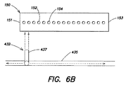
図6Bは溶剤を印刷ヘッドノズルプレート150に適用するためのさらに別の及び/又は補足的な配置実施形態の底面図であり、ノズルプレート150の全域に溶剤を噴霧するために、噴霧器432は進路に沿って移動するよう構成されている。噴霧器432をレール435に連結し、噴霧制御装置170の指示によりモータ(図示せず)で駆動してノズルプレート150の縦寸法と平行なレールに沿って移動させる。この実施形態において、図6Aに図示の実施形態と同様に、噴霧器はノズルプレートの縦寸法にほぼ直角の方向に溶剤の線形流れを噴射するよう構成されたノズル437を備え、レール435に沿って連続的に、又は非連続した段階的に噴霧器432を移動させることで最適なノズル露出が達成され、これにより、その全長にわたりノズルプレート150に向かって噴霧を指向させることができる。
FIG. 6B is a bottom view of yet another and / or supplemental arrangement for applying solvent to the
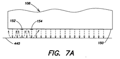
図7A及び7Bに図示の補足的及び/又は別の実施形態においては、異なる溶剤適用法を使用する。これらの実施形態においては、ノズルプレート150のインクノズル、例えば152、154を、インクの代わりに溶剤を印刷ヘッドに循環させるパージ法を用いて溶剤で洗浄する。印刷ヘッドのパージ法は、例えば、上記で本願に組み込んだ米国特許仮出願第60/721340号「インクジェット送出モジュール」に記載されている。待機構造体内の印刷ヘッド108の断面図である図7Aにおいて、溶剤はノズルプレート150と平行かつ近接して配置された跳ね返り面445に向かってノズル152、154を通して噴射される。跳ね返り面445はいずれの適切な弾性又は非弾性材料で形成することができ、ノズルプレート150から選択したクリアランス距離にまで上昇(又は印刷ヘッドを降下)させる。作動中、パージ工程中に溶剤がノズルプレート150のノズル152、154を通して噴射されるにつれ、溶剤は跳ね返り面445に叩きつけられ、溶剤の一部は表面445から様々な角度でノズルプレート150、特にはノズル152、154との間のノズルプレート150上に跳ね返る。
In the supplemental and / or alternative embodiments illustrated in FIGS. 7A and 7B, different solvent application methods are used. In these embodiments, the ink nozzles, eg, 152, 154, of the
図7Bの断面図において、印刷ヘッド108は、そのノズルプレート165を上方向に向け対向して配置されたノズル160列(例えば、第2印刷ヘッド)に整列(又はほぼ整列)かつ面するように待機されている。ノズル列160を流体槽(図示せず)に連結してパージモードで作動させ、溶剤をそのノズル、例えば162、164から待機印刷ヘッド108の対向するノズルプレート150に噴射してもよい。ノズルプレート150、165の相対的な配列を調整してノズルプレート150と165とを若干ずらした構成とする場合、ノズル列160のノズル、例えば162、164はノズル152、154の縁部又はノズル152、154の間のノズルプレート150の一部に面する。実施形態によっては、ノズル列160は上向き印刷ヘッドとして構成される。実施形態によっては、ノズル列160を印刷ヘッド108に相対して移動(例えば、往復運動)させ、ノズルプレート150の複数の領域を多角的に溶剤噴霧する。
In the cross-sectional view of FIG. 7B, the
実施形態によっては、ノズルプレート150の特定の領域を、例えば画像化システム124(図1)からの情報に基づいてノズル列160の特定のノズル162、164を用いて標的とする。例えば、画像化システム124は、ノズルXに対応する特定のピクセルウェル列に沿ってインクが印刷ヘッドによって堆積されないことから、印刷ヘッドY上のノズルXが目詰まりしている可能性があると判断する。印刷ヘッドYが待機構造体116内に一旦待機すると、印刷ヘッドY上のノズルX付近に噴霧するよう整列させたノズル列160上の溶剤噴霧ノズルが作動して、ノズルX付近に溶剤を噴霧して目詰まりを解消する。
In some embodiments, specific areas of the
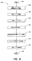
図8には、待機構造体116内の印刷ヘッド108を処理するための方法例500が示されている。方法500は工程502から開始される。工程504において、印刷ヘッド108は待機構造体116内に密閉される。作動中、システム制御装置114はシステム100に、印刷作業終了後、開始前、及び/又はその最中に待機構造体116上の待機位置へと印刷ヘッド108を戻すよう指示する。待機位置は、インクジェット印刷システム100がシステム制御装置114のメモリに記憶するところの既知の位置である。実施形態によっては、待機位置は、待機構造体116及び/又は印刷ヘッド108上に配置したセンサ又はその他のデバイスの使用を通して測定又は検証される。印刷ヘッド108が一旦待機位置に置かれると、アクチュエータ410(図4A)はシステム制御装置114の指示により待機構造体116を上昇させ、封止部302が印刷ヘッド108の表面と係合する。
FIG. 8 illustrates an
実施形態によっては、待機構造体116を別の位置で保持するようアクチュエータを構成する。第1位置は(例えば、溶剤又は表面処理剤、又は例えば印刷ヘッド108を乾燥させるためのCDAを)印刷ヘッドノズルプレート150に噴霧、又は印刷ヘッドを待機構造体116内に位置させた状態で印刷ヘッド108を点検/試験するのに有用である(例えば、印刷ヘッド108の出力を溶剤を噴出中に検査する)。第2位置は、表面処理等のその他の作業に有用である。どちらの位置の場合でも、封止部302と印刷ヘッド108との間の接触は維持されるため、インク、溶剤、表面処理溶液その他は待機構造体116内に閉じ込められる。従って、画像化システム124に接続された、及び/又はその一部であるカメラ(図示せず)を、待機構造体116内に配置してもよい。それに加えて又はそれとは別に、待機構造体116は、待機構造体116内に印刷ヘッド108がある際にそれを通して印刷ヘッド108を検査し得る窓(図示せず)を備えていてもよい。
In some embodiments, the actuator is configured to hold the
印刷ヘッドが待機構造体116内に一旦密閉されると、印刷ヘッド108は続いて工程506で噴霧に供される。実施形態によっては、印刷ヘッド108を噴霧に先立って溶剤浴に浸漬する。工程508においては、印刷ヘッド108内に残留するインクを全て、インク供給を遮断した状態で印刷ヘッド108の各ノズルを噴射させることでパージする。実施形態によっては、その後、印刷ヘッド108の各ノズルを通して溶剤のみの溶液を噴射することで溶剤パージする。一般的に、印刷ヘッド108からインクをパージするには、適切な方法により、インクジェット印刷ヘッド108の内部に残留しているインクを押し出す。上述したように、これは、例えば、印刷ヘッド108を通してインク及び/又は空気を噴射することを含む。1つ以上の実施形態において、インク及び/又は空気は、その他の実用的なパルス幅も使用し得るが、約0.5秒間隔のパルスで印刷ヘッド108を通して噴射される。模範実施形態において、印刷ヘッド108は1サイクルあたり約3〜6cm3のインクをパージする。印刷ヘッド108は洗浄ステーション122の洗浄媒体上及び/又は上述したように待機構造体116内にパージされる。
Once the print head is sealed within the
印刷ヘッド108のノズルプレート150(印刷ヘッドノズル、例えば152、154を含む)をある期間にわたって適切に噴霧した後、工程510で待機構造体から使用済みの溶剤と溶解したインクを排液ライン406を介して排出する。実施形態によっては、印刷ヘッド108に溶剤を非常に短時間にわたって噴霧する。別の実施形態においては、印刷ヘッド108に長時間にわたって噴霧を施す(例えば、分、時間、等)。実施形態によっては、アクチュエータ410により待機構造体116を下降させることで、操作者及び/又はシステム100は印刷ヘッド108を検査(例えば、画像化システム124を使用して)及び/又は試験して印刷ヘッド108にインクが残っているかどうかを判断できる。実施形態によっては、印刷ヘッド108を待機構造体から移動させて試験/検査する。インクが残留している場合は、さらに噴霧し場合によってはパージ、噴霧、点検等のサイクルを追加して行うために、印刷ヘッド108を待機構造体116内の噴霧位置へと戻してもよい。
After properly spraying the
工程510で溶剤を排出した後、また印刷ヘッド108が待機構造体116内にある間(又は戻った後)、印刷ヘッド108にCDAを噴霧して印刷ヘッド108を乾燥させる。印刷ヘッド108が一旦乾燥したら、待機ステーション116を下降させて封止部302を離脱させ、印刷ヘッド108は印刷作業開始準備状態又は作業に戻る。
After draining the solvent at
実施形態によっては、印刷ヘッド108を乾燥させる前又は乾燥させた後、工程512で印刷ヘッドを疎インク表面処理溶液で処理する。別の実施形態においては、工程512の前に印刷ヘッド108を乾燥させない。実施形態によっては、印刷ヘッド108の処理手順の一部として、溶液に熱も加える。溶剤と同じく、実施形態によっては、印刷ヘッド108には疎インク表面処理溶液をごく短時間にわたって噴霧するだけである。別の実施形態においては、印刷ヘッド108に疎インク表面処理溶液を長時間(例えば、分、時間等)にわたって噴霧する。適切に表面処理加工を施した後、印刷ヘッド108を工程514で(例えば、CDAを用いて)乾燥させ、待機構造体を下降させて封止部302を離脱させると、印刷ヘッド108は工程516で印刷作業を開始準備状態又は継続可能となる。方法500はステップ518で終了する。
In some embodiments, before or after the
本発明の態様には、印刷ヘッド108のノズル表面を疎水性又は疎インク性材料でコーティング又は処理することが含まれる。コーティングにより噴射信頼性と液滴サイズ再現性が改善される。使用するインク及びその他の要素に応じて、多くの異なるタイプのコーティングを使用し得る。例えば、アルキルチオールとイオン性アルキルチオールとの混合物を溶剤に溶解して、表面処理用の溶液を生成する。一部の実施形態においては、例えば、溶剤中のアルキルチオールとイオン性アルキルチオールの比は約0.5〜5mM:0.3〜5mMである。実施形態によっては、表面処理溶液はその分子が「活性」な端部(例えば、ノズル表面に結合する分子端部)に硫黄原子又は窒素原子のいずれかを、もう一方の疎インク性の分子端にフッ化炭素基(例えば、CFx。xはいずれの数字)を含む材料から形成される。例にはCF3(CF2)xCF2C2H4SH、例えば1H、1H、2H、2H−ペルフルオロ−1−デカンチオール3、3、4、4、5、5、6、6、7、7、8、8、9、9、10、10、10−ヘプタデカフルオロ−1−デカンチオールと1H、1H、2H、2H―ペルフルオロー1−ヘキサンチオール3、3、4、4、5、5、6、6、6−ノナフルオロ−1−ヘキシルメルカプタンが含まれる。
Aspects of the present invention include coating or treating the nozzle surface of the
作動中、印刷ヘッド108には一定間隔(例えば、1回以上の印刷パス後、印刷ヘッド洗浄後、不使用期間後その他)で表面処理溶液を噴霧してもよい。実施形態によっては、表面処理溶液を用いて、フラットパネルディスプレイ用カラーフィルタの印刷に加え、その他の堆積工程を促進する。
During operation, the surface treatment solution may be sprayed onto the
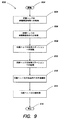
図9は、方法600の印刷作業を示す。方法600は工程602から開始される。実施形態によっては、基板106を装填又はステージから除去する間、印刷ヘッド108、110、112は各待機構造体116、118、120内に密閉されたままである。従って、工程604において、印刷ヘッド108、110、112は各待機構造体116、118、120内に格納されている。
FIG. 9 shows the printing operation of
工程606において、図8に関連して上述した方法に従って印刷ヘッド108、110、112を各待機構造体116、118、120内で処理する。例えば、印刷ヘッド108、110、112に待機構造体116、118、120内で溶剤を噴霧する。さらに、印刷ヘッド108、110、112を待機構造体116、118、120内でパージ及び/又は点検してもよい。実施形態によっては、印刷ヘッド108、110、112に各待機構造体116、118、120内でノズル表面処理を施す及び/又はCDAで乾燥させる。
In
実施形態によっては、続いて工程608で1つ以上の印刷ヘッド108、110、112を洗浄ステーション112に移動させ、そこで印刷ヘッド108、110、112をさらに処理する。例えば、印刷ヘッド108、110、112を拭き取る、又は上記で本願に組み込んだ米国特許出願第11/238631号に記載されるように別の方法で調整する。また、工程612では、印刷ヘッド108、110、112を洗浄ステーション122で予備噴射もさせてシステム100内のインク圧を安定化させる。
In some embodiments, subsequently, at
工程614では、印刷ヘッド108、110、112を印刷位置へと戻して印刷を開始又は継続する。別の実施形態においては、待機構造体116、118、120でノズルに表面処理を施す前に洗浄ステーション122で拭き取りを行う。次の基板を処理する前に、印刷ヘッド108、110、112を各待機構造体116、118、120に戻してもよい。別の実施形態においては、待機構造体116、118、120及び洗浄ステーション122の使用順序は様々に異なるものを使用することができる。例えば、溶剤又は表面処理剤噴霧を行うために、印刷ヘッド108、110、112を印刷パス毎に各待機構造体116、118、120に戻す。工程616で、方法600は終了する。
In
前述の記載は本発明の典型的な実施形態を開示するにすぎず、上述で開示の方法及び装置の本発明の範囲内での改変は当業者に明白である。例えば、上述の方法例は、図1を参照して記載したように、印刷ヘッド1つにつき待機構造体1つとして一般的に説明したが、いずれの適切な数の待機構造体(例えば、2、3、4個等)を用いて応用し得ることを当業者は理解できる。 The foregoing description discloses only exemplary embodiments of the invention, and modifications within the scope of the invention of the methods and apparatus disclosed above will be apparent to those skilled in the art. For example, although the example method described above has generally been described with one standby structure per printhead, as described with reference to FIG. 1, any suitable number of standby structures (e.g., 2 Those skilled in the art can understand that the present invention can be applied using three, four, etc.).
実施形態によっては、待機構造体116の位置は実用的なものであればよく、可動式プラットフォームに搭載して、印刷ヘッド108を待機構造体116に移動させる代わりに待機構造体116を印刷ヘッド108に移動させることを含む。
In some embodiments, the position of the
実施形態によっては、本発明のインクジェット印刷ヘッド待機ステーションは、2004年11月4日出願の米国特許仮出願第60/625550号「インクジェット法によるフラットパネルディスプレイ用カラーフィルタの製造装置及び方法」に開示されるようなインクジェット印刷システム上に搭載及び/又はシステムと共に使用される。さらに、本発明はスペーサ形成、偏光子コーティング、ナノ粒子回路形成のための工程に応用することもできる。 In some embodiments, the ink jet print head standby station of the present invention is disclosed in US Provisional Patent Application No. 60 / 625,550 entitled “Apparatus and Method for Manufacturing Color Filter for Flat Panel Display by Ink Jet Method” filed on Nov. 4, 2004. Mounted on and / or used with an ink jet printing system. Furthermore, the present invention can be applied to processes for spacer formation, polarizer coating, and nanoparticle circuit formation.
従って、本発明をその特定の実施形態に関連させて開示してきたが、特許請求の範囲で規定されるように、その他の実施形態も本発明の精神と範囲に含まれると理解されるべきである。 Thus, while the invention has been disclosed in connection with specific embodiments thereof, it is to be understood that other embodiments are within the spirit and scope of the invention as defined by the claims. is there.
Claims (24)
筺体に隣接し、印刷ヘッドを受け止めると筺体内において印刷ヘッドが噴霧装置に露出されるよう構成した待機場所とを含む印刷ヘッド待機構造体。 A housing including a spraying device;
A print head standby structure including a standby location adjacent to the housing and configured to expose the print head to the spray device within the housing upon receipt of the print head.
筺体が使用済み溶剤を排液するよう構成されている請求項1記載の印刷ヘッド待機構造体。 The spraying device is configured to spray at least one of a solvent, a surface treatment solution, and a combination of a solvent and a surface treatment solution;
The print head standby structure according to claim 1, wherein the casing is configured to drain the used solvent.
印刷ヘッドのその他の部分に飛散させることなく溶剤を印刷ヘッドのノズルプレートに噴霧することを含む方法。 Sealing the print head in the standby structure,
Spraying the solvent onto the nozzle plate of the print head without splashing to other parts of the print head.
噴霧装置と、印刷ヘッドを受け止めるとその内部で受け止めた印刷ヘッドのノズルプレートが噴霧装置に露出されるよう構成した待機場所とを有する筺体とを含む印刷ヘッド待機構造体とを含むシステム。 An inkjet printer adapted for manufacturing color filters for flat panel displays and including a plurality of print heads each provided with a nozzle plate;
A system comprising: a printhead standby structure including a spray device and a housing having a standby location configured to receive a printhead nozzle plate received therein to be exposed to the sprayer when the printhead is received.
筺体が使用済み溶剤を排液するよう構成されている請求項16記載のシステム。 The spraying device is configured to spray at least one of a solvent, a surface treatment solution, a combination of a solvent and a surface treatment solution,
The system of claim 16, wherein the enclosure is configured to drain spent solvent.
Applications Claiming Priority (3)
| Application Number | Priority Date | Filing Date | Title |
|---|---|---|---|
| US79629706P | 2006-04-29 | 2006-04-29 | |
| US79570906P | 2006-04-29 | 2006-04-29 | |
| US11/493,310 US20070252863A1 (en) | 2006-04-29 | 2006-07-26 | Methods and apparatus for maintaining inkjet print heads using parking structures with spray mechanisms |
Publications (2)
| Publication Number | Publication Date |
|---|---|
| JP2007296522A true JP2007296522A (en) | 2007-11-15 |
| JP2007296522A5 JP2007296522A5 (en) | 2010-06-17 |
Family
ID=38766457
Family Applications (1)
| Application Number | Title | Priority Date | Filing Date |
|---|---|---|---|
| JP2007120511A Pending JP2007296522A (en) | 2006-04-29 | 2007-05-01 | Method and apparatus for maintaining inkjet print head using parking structure with spray mechanism |
Country Status (2)
| Country | Link |
|---|---|
| JP (1) | JP2007296522A (en) |
| KR (1) | KR20070106472A (en) |
Cited By (3)
| Publication number | Priority date | Publication date | Assignee | Title |
|---|---|---|---|---|
| JP2011197161A (en) * | 2010-03-17 | 2011-10-06 | Ricoh Co Ltd | Method and device for producing toner, and toner |
| JPWO2012147157A1 (en) * | 2011-04-26 | 2014-07-28 | 株式会社日立製作所 | Energy storage and supply equipment |
| JP2020073329A (en) * | 2018-12-25 | 2020-05-14 | セイコーエプソン株式会社 | Liquid jet device |
Families Citing this family (6)
| Publication number | Priority date | Publication date | Assignee | Title |
|---|---|---|---|---|
| US10434804B2 (en) | 2008-06-13 | 2019-10-08 | Kateeva, Inc. | Low particle gas enclosure systems and methods |
| US9048344B2 (en) | 2008-06-13 | 2015-06-02 | Kateeva, Inc. | Gas enclosure assembly and system |
| US10442226B2 (en) | 2008-06-13 | 2019-10-15 | Kateeva, Inc. | Gas enclosure assembly and system |
| WO2015100375A1 (en) | 2013-12-26 | 2015-07-02 | Kateeva, Inc. | Thermal treatment of electronic devices |
| JP6113923B2 (en) | 2014-01-21 | 2017-04-12 | カティーバ, インコーポレイテッド | Apparatus and techniques for encapsulation of electronic devices |
| KR102390045B1 (en) | 2014-04-30 | 2022-04-22 | 카티바, 인크. | Gas cushion apparatus and techniques for substrate coating |
Citations (6)
| Publication number | Priority date | Publication date | Assignee | Title |
|---|---|---|---|---|
| JPH0224148A (en) * | 1988-07-13 | 1990-01-26 | Matsushita Electric Ind Co Ltd | Ink jet recorder |
| JPH0671897A (en) * | 1992-04-06 | 1994-03-15 | Canon Inc | Liquid injection device, recover method for ink jet recording and recording device |
| JPH0780385A (en) * | 1993-09-10 | 1995-03-28 | Hirata Corp | Coating head cleaning device and cleaning method of coating head |
| JP2001232250A (en) * | 1999-12-17 | 2001-08-28 | Tokyo Electron Ltd | Membrane forming apparatus |
| JP2005028758A (en) * | 2003-07-14 | 2005-02-03 | Fuji Xerox Co Ltd | Cleaning equipment of ink jet recording head and ink jet recorder |
| JP2007008103A (en) * | 2005-07-04 | 2007-01-18 | Ulvac Japan Ltd | Cleaning and holding device, printer, holding method for printing member, and printing method |
-
2007
- 2007-04-30 KR KR1020070042073A patent/KR20070106472A/en not_active Application Discontinuation
- 2007-05-01 JP JP2007120511A patent/JP2007296522A/en active Pending
Patent Citations (6)
| Publication number | Priority date | Publication date | Assignee | Title |
|---|---|---|---|---|
| JPH0224148A (en) * | 1988-07-13 | 1990-01-26 | Matsushita Electric Ind Co Ltd | Ink jet recorder |
| JPH0671897A (en) * | 1992-04-06 | 1994-03-15 | Canon Inc | Liquid injection device, recover method for ink jet recording and recording device |
| JPH0780385A (en) * | 1993-09-10 | 1995-03-28 | Hirata Corp | Coating head cleaning device and cleaning method of coating head |
| JP2001232250A (en) * | 1999-12-17 | 2001-08-28 | Tokyo Electron Ltd | Membrane forming apparatus |
| JP2005028758A (en) * | 2003-07-14 | 2005-02-03 | Fuji Xerox Co Ltd | Cleaning equipment of ink jet recording head and ink jet recorder |
| JP2007008103A (en) * | 2005-07-04 | 2007-01-18 | Ulvac Japan Ltd | Cleaning and holding device, printer, holding method for printing member, and printing method |
Cited By (3)
| Publication number | Priority date | Publication date | Assignee | Title |
|---|---|---|---|---|
| JP2011197161A (en) * | 2010-03-17 | 2011-10-06 | Ricoh Co Ltd | Method and device for producing toner, and toner |
| JPWO2012147157A1 (en) * | 2011-04-26 | 2014-07-28 | 株式会社日立製作所 | Energy storage and supply equipment |
| JP2020073329A (en) * | 2018-12-25 | 2020-05-14 | セイコーエプソン株式会社 | Liquid jet device |
Also Published As
| Publication number | Publication date |
|---|---|
| KR20070106472A (en) | 2007-11-01 |
Similar Documents
| Publication | Publication Date | Title |
|---|---|---|
| US20070252863A1 (en) | Methods and apparatus for maintaining inkjet print heads using parking structures with spray mechanisms | |
| KR101521901B1 (en) | A method for filming ink-jet | |
| JP2007296522A (en) | Method and apparatus for maintaining inkjet print head using parking structure with spray mechanism | |
| US20070263026A1 (en) | Methods and apparatus for maintaining inkjet print heads using parking structures | |
| JP4792787B2 (en) | Coating device with cleaning device | |
| US20070256709A1 (en) | Methods and apparatus for operating an inkjet printing system | |
| JP2007244973A (en) | Liquid droplet spraying apparatus, and method of manufacturing coated body | |
| JP5364309B2 (en) | Droplet spray coating apparatus and coating body manufacturing method | |
| KR101094388B1 (en) | Method of coating treatment solution | |
| JP4259107B2 (en) | Droplet discharge head cleaning device, droplet discharge head cleaning method, and droplet discharge device | |
| JP2004337709A (en) | Droplet discharging apparatus, color filter production apparatus, color filter and its production method, liquid crystal device, and electronic device | |
| JP4487628B2 (en) | Coating device with cleaning device | |
| KR102573601B1 (en) | Head cleaning unit and apparatus for treating substrate including the same | |
| JP2006142621A (en) | Ink jet application apparatus | |
| JP2010051839A (en) | Cleaning device | |
| JP4746453B2 (en) | Method for manufacturing application body and droplet ejecting apparatus | |
| TWI834283B (en) | Coating device and droplet discharge inspection method | |
| TW202310932A (en) | Coating device and droplet ejection inspection method capable of suppressing drying of droplets ejected onto inspection medium and appropriately performing droplet inspection |
Legal Events
| Date | Code | Title | Description |
|---|---|---|---|
| A521 | Written amendment |
Free format text: JAPANESE INTERMEDIATE CODE: A523 Effective date: 20100428 |
|
| A621 | Written request for application examination |
Free format text: JAPANESE INTERMEDIATE CODE: A621 Effective date: 20100430 |
|
| A521 | Written amendment |
Free format text: JAPANESE INTERMEDIATE CODE: A523 Effective date: 20100512 |
|
| A977 | Report on retrieval |
Free format text: JAPANESE INTERMEDIATE CODE: A971007 Effective date: 20120920 |
|
| A131 | Notification of reasons for refusal |
Free format text: JAPANESE INTERMEDIATE CODE: A131 Effective date: 20121023 |
|
| A601 | Written request for extension of time |
Free format text: JAPANESE INTERMEDIATE CODE: A601 Effective date: 20130122 |
|
| A602 | Written permission of extension of time |
Free format text: JAPANESE INTERMEDIATE CODE: A602 Effective date: 20130125 |
|
| A601 | Written request for extension of time |
Free format text: JAPANESE INTERMEDIATE CODE: A601 Effective date: 20130220 |
|
| A602 | Written permission of extension of time |
Free format text: JAPANESE INTERMEDIATE CODE: A602 Effective date: 20130225 |
|
| A601 | Written request for extension of time |
Free format text: JAPANESE INTERMEDIATE CODE: A601 Effective date: 20130319 |
|
| A602 | Written permission of extension of time |
Free format text: JAPANESE INTERMEDIATE CODE: A602 Effective date: 20130325 |
|
| A02 | Decision of refusal |
Free format text: JAPANESE INTERMEDIATE CODE: A02 Effective date: 20130625 |