JP2007294285A - Ion generator, and electric apparatus equipped with it - Google Patents
Ion generator, and electric apparatus equipped with it Download PDFInfo
- Publication number
- JP2007294285A JP2007294285A JP2006121631A JP2006121631A JP2007294285A JP 2007294285 A JP2007294285 A JP 2007294285A JP 2006121631 A JP2006121631 A JP 2006121631A JP 2006121631 A JP2006121631 A JP 2006121631A JP 2007294285 A JP2007294285 A JP 2007294285A
- Authority
- JP
- Japan
- Prior art keywords
- discharge
- electrode
- ion generator
- discharge part
- voltage
- Prior art date
- Legal status (The legal status is an assumption and is not a legal conclusion. Google has not performed a legal analysis and makes no representation as to the accuracy of the status listed.)
- Pending
Links
Images


Abstract
Description
本発明は、プラスイオンとマイナスイオンを空間に放出することにより、空気中に浮遊する細菌やカビ菌、有害物質等を分解することが可能なイオン発生装置及びこれを備えた電気機器に関するものである。 The present invention relates to an ion generator capable of decomposing bacteria, fungi, harmful substances, etc. floating in the air by releasing positive ions and negative ions into the space, and an electric device equipped with the same. is there.
現在、セラミックの誘電体を挟んで外側に放電電極、内側に誘導電極を配設した構造のイオン発生素子を有するイオン発生装置がある。そして、浮遊カビ菌等を不活化することが可能なイオン発生装置は、プラスイオンとマイナスイオンを発生させている。 At present, there is an ion generating device having an ion generating element having a structure in which a discharge electrode is disposed outside a ceramic dielectric and an induction electrode is disposed inside. And the ion generator which can inactivate floating mold | fungi etc. is generating the positive ion and the negative ion.
正負両極性のイオンを発生させる方式の一つに、1つの放電部に交流高電圧を印加する方式がある。このような方式は、プラスイオンとマイナスイオンが1つの放電部からほぼ同時に発生するため、イオンの発生とともに正負両極性のイオンの一部が中和して消滅してしまいイオン発生効率が良くないという課題がある。 One method for generating positive and negative bipolar ions is to apply an alternating high voltage to one discharge unit. In such a system, since positive ions and negative ions are generated almost simultaneously from one discharge part, some of the positive and negative ions are neutralized and disappear together with the generation of ions, resulting in poor ion generation efficiency. There is a problem.
かかる課題を解決することができる正負両極性のイオンを発生させる方式として、少なくとも2つの放電部にそれぞれ正負逆極性の高電圧を印加し、それぞれの放電部でプラスイオンとマイナスイオンを個別に発生させ、各々を独立して空間に放出する方式(以下、イオン独立放出方式という)がある(例えば、特許文献1を参照)。
しかしながら、従来のイオン独立放出方式では、少なくとも2つの放電部にそれぞれ正負逆極性の高電圧を印加するために、通常、複数のトランス又は少なくとも2つの二次巻線を有するトランスが必要となり(例えば、特許文献1を参照)、装置の高コスト化及び大型化を招くことになるという課題が発生する。 However, in the conventional ion independent emission method, in order to apply a high voltage of positive / negative / reverse polarity to at least two discharge parts, a plurality of transformers or a transformer having at least two secondary windings is usually required (for example, , Refer to Patent Document 1), and there is a problem that the cost and the size of the apparatus are increased.
本発明は、上記の課題に鑑み、低コスト化及び小型化を図ることができるイオン発生装置及びこれを備えた電気機器を提供することを目的とする。 An object of this invention is to provide the ion generator which can achieve cost reduction and size reduction, and an electric equipment provided with the same in view of said subject.
上記目的を達成するために本発明に係るイオン発生装置は、放電部を少なくとも2つ備え、前記放電部の一つである第1放電部の放電電極と前記放電部の他の一つである第2放電部の誘導電極とが電気的に接続され、前記第1放電部の誘導電極と前記第2放電部の放電電極とが電気的に接続され、前記第1放電部の放電電極及び前記第2放電部の誘導電極の共通接続点と前記第1放電部の誘導電極及び前記第2放電部の放電電極の共通接続点との間に高電圧を印加する電圧印加部を備えるようにする。 In order to achieve the above object, an ion generator according to the present invention includes at least two discharge units, and is a discharge electrode of a first discharge unit which is one of the discharge units and another one of the discharge units. An induction electrode of the second discharge part is electrically connected, an induction electrode of the first discharge part and a discharge electrode of the second discharge part are electrically connected, and the discharge electrode of the first discharge part and the A voltage application unit for applying a high voltage is provided between the common connection point of the induction electrode of the second discharge unit and the common connection point of the induction electrode of the first discharge unit and the discharge electrode of the second discharge unit. .
このような構成によると、前記電圧印加部が、前記第1放電部の放電電極及び前記第2放電部の誘導電極の共通接続点と前記第1放電部の誘導電極及び前記第2放電部の放電電極の共通接続点との間に高電圧を印加するだけで、前記第1放電部(より詳細には前記第1放電部の放電電極近傍)と前記第2放電部(より詳細には前記第2放電部の放電電極近傍)から互いに異なる極性のイオンが放出されるので、複数のトランス又は少なくとも2つの二次巻線を有するトランスを必要としない。したがって、低コスト化及び小型化を図ることができる。 According to such a configuration, the voltage application unit includes a common connection point between the discharge electrode of the first discharge unit and the induction electrode of the second discharge unit, and the induction electrode of the first discharge unit and the second discharge unit. By simply applying a high voltage between the common connection points of the discharge electrodes, the first discharge part (more specifically, the vicinity of the discharge electrode of the first discharge part) and the second discharge part (more specifically, the above-mentioned details) Since ions having different polarities are emitted from the vicinity of the discharge electrode of the second discharge part), a plurality of transformers or a transformer having at least two secondary windings is not required. Therefore, cost reduction and size reduction can be achieved.
また、上記構成のイオン発生装置において、前記高圧印加部の出力端部に、前記高電圧の極性が切り替わらない手段を設けることが望ましい。 Moreover, in the ion generator of the said structure, it is desirable to provide the means by which the polarity of the said high voltage does not switch in the output terminal part of the said high voltage application part.
前記高電圧の極性が固定されると、前記第1放電部から放出されるイオンの極性と前記第2放電部から放出されるイオンの極性がそれぞれ固定されるので、同一放電部において時間的にイオンの極性が切り替わることによるイオンの中和が起こらなくなり、イオン発生効率を向上させることができる。なお、前記高電圧の極性が切り替わらない手段としては、例えば、整流手段やバイアス手段等が挙げられる。 When the polarity of the high voltage is fixed, the polarity of the ions emitted from the first discharge part and the polarity of the ions emitted from the second discharge part are fixed. Ion neutralization due to switching of the polarity of ions does not occur, and ion generation efficiency can be improved. Examples of means that do not switch the polarity of the high voltage include rectifier means and bias means.
また、上記目的を達成するために本発明に係る電気機器は、上記構成のイオン発生装置と、前記イオン発生装置で発生したイオンを空気中に送出する送出手段とを備えるようにする。 In order to achieve the above object, an electrical apparatus according to the present invention includes the ion generator having the above-described configuration and a sending means for sending ions generated by the ion generator into the air.
本発明によると、複数のトランス又は少なくとも2つの二次巻線を有するトランスを必要としないので、イオン発生装置及び電気機器の低コスト化及び小型化を図ることができる。 According to the present invention, since a plurality of transformers or a transformer having at least two secondary windings is not required, it is possible to reduce the cost and size of the ion generator and the electric equipment.
本発明の実施形態について図面を参照して以下に説明する。図1は、本発明に係るイオン発生装置の一実施形態を示す概略構成図であり、本図(a)、(b)は、それぞれイオン発生装置の平面図及び側面断面図を模式的に示している。 Embodiments of the present invention will be described below with reference to the drawings. FIG. 1 is a schematic configuration diagram showing an embodiment of an ion generator according to the present invention, and FIGS. 1A and 1B schematically show a plan view and a side sectional view of the ion generator, respectively. ing.
図1に示すように、本発明に係るイオン発生装置は、イオンを発生する放電部を複数(本実施形態では2つ)備えたイオン発生素子10と、イオン発生素子10に対して所定の電圧印加を行う電圧印加部20と、イオン発生素子10と電圧印加部20との間を電気的に接続するリード線12p、12q、13p、及び13qとを有して成る。
As shown in FIG. 1, the ion generator according to the present invention includes an
イオン発生素子10は、誘電体11(上部誘電体11a及び下部誘電体11b)と、第1放電部12(放電電極12a、誘導電極12b、放電電極接点12c、誘導電極接点12d、接続端子12e及び12f、並びに接続経路12g及び12h)と、第2放電部13(放電電極13a、誘導電極13b、放電電極接点13c、誘導電極接点13d、接続端子13e及び13f、並びに接続経路13g及び13h)と、コーティング層14とを有して成る。
The
放電電極接点12c、13cは、放電電極12a、13aと同一形成面(すなわち上部誘電体11aの表面)に設けられた接続端子12e、13e、及び接続経路12g、13gを介して、放電電極12a、13aと電気的に導通されている。そして、放電電極接点12c、13cにリード線(銅線やアルミ線など)12p、13pの一端が接続され、リード線12p、13pの他端に電圧印加部20が接続されて、放電電極12a、13aと電圧印加部20とが電気的に導通されている。
The
また、誘導電極接点12d、13dは、誘導電極12b、13bと同一形成面(すなわち下部誘電体11bの表面)に設けられた接続端子12f、13f、及び接続経路12h、13hを介して、誘導電極12b、13bと電気的に導通されている。そして、誘導電極接点12d、13dにリード線(銅線やアルミ線など)12q、13qの一端が接続され、リード線12q、13qの他端に電圧印加部20が接続されて、誘導電極12b、13bと電圧印加部20とが電気的に導通されている。
The
電圧印加部20が第1放電部12の放電電極12aと誘導電極12bとの間及び第2放電部13の放電電極13aと誘導電極13bとの間に後述の電圧印加を行うと、プラスイオンであるH+(H2O)m(mは任意の自然数)及びマイナスイオンであるO2 -(H2O)n(nは任意の自然数)が発生する。これにより、空気中にH+(H2O)mとO2 -(H2O)nが放出されることにより、これらのイオンが空気中の浮遊カビ菌やウィルスの周りを取り囲み、その際生成される活性種の水酸基ラジカル(・OH)の作用により不活化することが可能となる。
When the
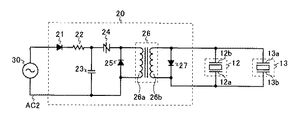
次に、電圧印加部20の構成及び動作について図2を参照して説明する。図2は図1に示すイオン発生装置の電気的構成を示す図である。なお、説明の便宜上、図1と同一の部分には同一の符号を付している。
Next, the configuration and operation of the
電圧印加部20は、入力電源30から電力を受け取る。電圧印加部20は、トランス26の1次側回路として、整流ダイオード21、入力抵抗22、コンデンサ23、トランス駆動用スイッチング素子24、及びダイオード25を有し、トランス26の2次側回路として整流ダイオード27を有する。トランス駆動用スイッチング素子24には、双方向導通可能とするトライアックや2端子サイリスタなどを用いる。
The
まずトランス26の1次側回路について説明する。入力電源30が交流商用電源の場合、入力電源30の電圧により、整流ダイオード21及び入力抵抗22を介して、コンデンサ23が充電され、コンデンサ23の両端電圧が規定電圧以上になればトランス駆動用スイッチング素子24がオンして、トランス26の1次側巻線26aに電圧が印加される。その直後、コンデンサ23に溜まっていた電荷はトランス駆動用スイッチング素子24とトランス26の1次側巻線26aを通じて放電され、コンデンサ23の両端電圧はゼロに戻り、トランス駆動用スイッチング素子24はオフとなり再びコンデンサ23の充電がされ、規定周期で充放電を繰り返す。なお、ダイオード25はトランス26の1次側巻線26aを流れる電流を早く停止させるフライホイールダイオードの役割を果たす。
First, the primary side circuit of the
続いてトランス26の2次側回路について説明する。トランス26の2次巻線26bの一端が第1放電部12の放電電極12a及び第2放電部13の誘導電極13bに接続されている。また、トランス26の2次巻線26bの他端が第1放電部12の誘導電極12b及び第2放電部13の放電電極13aに接続されている。1次側回路のトランス駆動用スイッチング素子24がオンすることにより、1次側のエネルギーがトランス26の2次巻線26bに伝達され、トランス26の2次巻線26bの両端間に整流ダイオード27が挿入されていない場合は、インパルス状電圧が発生する。これに対して、トランス26の2次巻線26bの両端間に整流ダイオード27が挿入されている場合は、インパルス状波形の第1波では、整流ダイオード27に逆バイアスがかかるため電圧が発生するが、インパルス状波形の第2波では、整流ダイオード27に順バイアスがかかり整流ダイオード27とトランス26の2次巻線26bとの間でエネルギー消費を起こすため、インパルス状波形の第1波のみの波形の電圧が発生する。
Next, the secondary side circuit of the
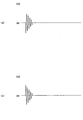
次に、動作電圧波形について説明する。まず、整流ダイオード27が挿入されていない場合すなわち図2に示す回路構成から整流ダイオード27を取り除いた場合について説明する。この場合、トランス26の2次巻線26bの両端には、図3に示すようなインパルス波形の交番電圧が発生する(整流ダイオード27のカソード側を基準にすると図3(a)の波形となり、整流ダイオード27のアノード側を基準にすると図3(b)の波形となる)。
Next, the operating voltage waveform will be described. First, the case where the rectifier diode 27 is not inserted, that is, the case where the rectifier diode 27 is removed from the circuit configuration shown in FIG. 2 will be described. In this case, an alternating voltage having an impulse waveform as shown in FIG. 3 is generated at both ends of the
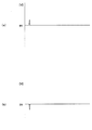
ここで、第1放電部12について説明する。図3(a)は、第1放電部12の放電電極12aを基準にしたときの誘導電極12bの電圧波形である。また、図4(a)は図2に示すラインAC2(場合によっては接地端子)を基準にしたときの放電電極12aの電圧波形であり、図4(b)は図2に示すラインAC2(場合によっては接地端子)を基準にしたときの誘導電極12bの電圧波形である。第1放電部12の放電電極12a近傍では、放電によってプラスイオンとマイナスイオン両方が瞬間的には生成されるが、図4(a)に示す放電電極12aの電位と逆極性のイオンは放電電極12aの電位によって中和され、図4(a)に示す放電電極12aの電位と同極性のイオンは放電電極12aの電位によって反発し放出されるため、図4(a)に示す波形の第1波目の放電でプラスイオン、第2波目の放電でマイナスイオンの順で交互にイオンが放出される。
Here, the
第2放電部13について同様に説明する。図3(b)は、第2放電部13の放電電極13aを基準にしたときの誘導電極13bの電圧波形である。また、図5(a)は図2に示すラインAC2(場合によっては接地端子)を基準にしたときの放電電極13aの電圧波形であり、図5(b)は図2に示すラインAC2(場合によっては接地端子)を基準にしたときの誘導電極13bの電圧波形である。第2放電部13の放電電極13a近傍では、放電によってプラスイオンとマイナスイオン両方が瞬間的には生成されるが、図5(a)に示す放電電極13aの電位と逆極性のイオンは放電電極13aの電位によって中和され、図5(a)に示す放電電極13aの電位と同極性のイオンは放電電極13aの電位によって反発し放出されるため、図5(a)に示す波形の第1波目の放電でマイナスイオン、第2波目の放電でプラスイオンの順で交互にイオンが放出される。
The
したがって、整流ダイオード27が挿入されていない場合すなわち図2に示す回路構成から整流ダイオード27を取り除いた場合では、第1放電部12と第2放電部13から互いに異なる極性のイオンが放出され、第1放電部12及び第2放電部13から放出される各イオンの極性は図3に示すインパルス波形の交番電圧の波毎に変化していることになる。
Therefore, when the rectifier diode 27 is not inserted, that is, when the rectifier diode 27 is removed from the circuit configuration shown in FIG. 2, ions having different polarities are emitted from the
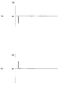
続いて、整流ダイオード27が挿入されている場合すなわち図2に示す回路構成の場合について説明する。この場合、トランス26の2次巻線26bの両端には、図6に示すような波形の電圧(図3に示すインパルス波形の交番電圧の第1波のみの電圧)が発生する(整流ダイオード27のカソード側を基準にすると図6(a)の波形となり、整流ダイオード27のアノード側を基準にすると図6(b)の波形となる)。 Next, the case where the rectifier diode 27 is inserted, that is, the case of the circuit configuration shown in FIG. 2 will be described. In this case, a voltage having a waveform as shown in FIG. 6 (a voltage of only the first wave of the alternating voltage of the impulse waveform shown in FIG. 3) is generated at both ends of the secondary winding 26b of the transformer 26 (rectifier diode 27). The waveform of FIG. 6A is obtained with reference to the cathode side of FIG. 6, and the waveform of FIG. 6B is obtained with reference to the anode side of the rectifier diode 27).
ここで、第1放電部12について説明する。図6(a)は、第1放電部12の放電電極12aを基準にしたときの誘導電極12bの電圧波形である。また、図7(a)は図2に示すラインAC2(場合によっては接地端子)を基準にしたときの放電電極12aの電圧波形であり、図7(b)は図2に示すラインAC2(場合によっては接地端子)を基準にしたときの誘導電極12bの電圧波形である。第1放電部12の放電電極12a近傍では、放電によってプラスイオンとマイナスイオン両方が瞬間的には生成されるが、図7(a)に示す放電電極12aのプラス電位と逆極性のマイナスイオンは放電電極12aのプラス電位によって中和され、図7(a)に示す放電電極12aのプラス電位と同極性のプラスイオンは放電電極12aのプラス電位によって反発し放出されるため、プラスイオンが放出される。
Here, the
第2放電部13について同様に説明する。図6(b)は、第2放電部13の放電電極13aを基準にしたときの誘導電極13bの電圧波形である。また、図8(a)は図2に示すラインAC2(場合によっては接地端子)を基準にしたときの放電電極13aの電圧波形であり、図8(b)は図2に示すラインAC2(場合によっては接地端子)を基準にしたときの誘導電極13bの電圧波形である。第2放電部13の放電電極13a近傍では、放電によってプラスイオンとマイナスイオン両方が瞬間的には生成されるが、図8(a)に示す放電電極13aのマイナス電位と逆極性のプラスイオンは放電電極13aのマイナス電位によって中和され、図8(a)に示す放電電極13aのマイナス電位と同極性のマイナスイオンは放電電極13aのマイナス電位によって反発し放出されるため、マイナスイオンが放出される。
The
したがって、整流ダイオード27が挿入されている場合すなわち図2に示す回路構成の場合では、第1放電部12からプラスイオン、第2放電部13からマイナスイオンを放出していることになる。
Therefore, in the case where the rectifier diode 27 is inserted, that is, in the case of the circuit configuration shown in FIG. 2, positive ions are emitted from the
上述した実施形態のイオン発生装置は、整流ダイオード27の有無にかかわらず、2次巻線が1つのトランスを1つ備える構成であり、複数のトランス又は少なくとも2つの二次巻線を有するトランスを必要としないので、低コスト化及び小型化を図ることができる。また、上述した実施形態のイオン発生装置は、イオン独立放出方式、すなわちそれぞれの放電部でプラスイオンとマイナスイオンを個別に発生させ、各々を独立して空間に放出する方式であるため、整流ダイオード27を設けて電圧印加部から出力される高電圧の極性が切り替わらないようにすることで、イオン発生効率を良くすることができる。 The ion generator of the embodiment described above has a configuration in which the secondary winding includes one transformer regardless of the presence or absence of the rectifier diode 27, and includes a plurality of transformers or a transformer having at least two secondary windings. Since it is not necessary, cost reduction and size reduction can be achieved. In addition, since the ion generator of the above-described embodiment is an ion independent emission method, that is, a method in which positive ions and negative ions are individually generated in the respective discharge units, and each is independently discharged into the space. 27 is provided so that the polarity of the high voltage output from the voltage application unit is not switched, so that the ion generation efficiency can be improved.
上述した本発明に係るイオン発生装置は、空気調和機、除湿器、加湿器、空気清浄機、冷蔵庫、ファンヒータ、電子レンジ、洗濯乾燥機、掃除機、殺菌装置などの電気機器に搭載するとよい。そして、かかる電気機器にはイオン発生装置で発生したイオンを空気中に送出する送出手段(例えば、送風ファン)を搭載するとよい。このような電気機器であれば、機器本来の機能に加えて、搭載したイオン発生装置及び送出手段で正負イオンを空気中に放出することができる。 The ion generator according to the present invention described above may be mounted on an electrical device such as an air conditioner, a dehumidifier, a humidifier, an air cleaner, a refrigerator, a fan heater, a microwave oven, a washing dryer, a vacuum cleaner, or a sterilizer. . And it is good to equip such an electric equipment with the sending means (for example, ventilation fan) which sends out the ion which generate | occur | produced with the ion generator in the air. In such an electric device, in addition to the original function of the device, positive and negative ions can be released into the air by the installed ion generator and delivery means.
10 イオン発生素子
11 誘電体
11a 上部誘電体
11b 下部誘電体
12 第1放電部
13 第2放電部
12a、13a 放電電極
12b、13b 誘導電極
12c、13c 放電電極接点
12d、13d 誘導電極接点
12e、12f、13e、13f 接続端子
12g、12h、13g、13h 接続経路
12P、12q、13p、13q リード線
14 コーティング層
20 電圧印加部
21 整流ダイオード
22 入力抵抗
23 コンデンサ
24 トランス駆動用スイッチング素子
25 ダイオード
26 トランス
26a トランスの1次側巻線
26b トランスの2次側巻線
27 整流ダイオード
30 入力電源
DESCRIPTION OF
Claims (3)
前記放電部の一つである第1放電部の放電電極と前記放電部の他の一つである第2放電部の誘導電極とが電気的に接続され、
前記第1放電部の誘導電極と前記第2放電部の放電電極とが電気的に接続され、
前記第1放電部の放電電極及び前記第2放電部の誘導電極の共通接続点と前記第1放電部の誘導電極及び前記第2放電部の放電電極の共通接続点との間に高電圧を印加する電圧印加部を備えることを特徴とするイオン発生装置。 Including at least two discharge parts,
A discharge electrode of the first discharge part, which is one of the discharge parts, and an induction electrode of the second discharge part, which is another one of the discharge parts, are electrically connected;
The induction electrode of the first discharge part and the discharge electrode of the second discharge part are electrically connected;
A high voltage is applied between a common connection point of the discharge electrode of the first discharge part and the induction electrode of the second discharge part and a common connection point of the induction electrode of the first discharge part and the discharge electrode of the second discharge part. An ion generator comprising a voltage application unit for applying.
Priority Applications (1)
| Application Number | Priority Date | Filing Date | Title |
|---|---|---|---|
| JP2006121631A JP2007294285A (en) | 2006-04-26 | 2006-04-26 | Ion generator, and electric apparatus equipped with it |
Applications Claiming Priority (1)
| Application Number | Priority Date | Filing Date | Title |
|---|---|---|---|
| JP2006121631A JP2007294285A (en) | 2006-04-26 | 2006-04-26 | Ion generator, and electric apparatus equipped with it |
Publications (1)
| Publication Number | Publication Date |
|---|---|
| JP2007294285A true JP2007294285A (en) | 2007-11-08 |
Family
ID=38764692
Family Applications (1)
| Application Number | Title | Priority Date | Filing Date |
|---|---|---|---|
| JP2006121631A Pending JP2007294285A (en) | 2006-04-26 | 2006-04-26 | Ion generator, and electric apparatus equipped with it |
Country Status (1)
| Country | Link |
|---|---|
| JP (1) | JP2007294285A (en) |
Cited By (2)
| Publication number | Priority date | Publication date | Assignee | Title |
|---|---|---|---|---|
| WO2010018724A1 (en) * | 2008-08-11 | 2010-02-18 | シャープ株式会社 | Ion generating device and electric device using the same |
| WO2012053314A1 (en) * | 2010-10-19 | 2012-04-26 | パナソニック株式会社 | High-voltage generating circuit, ion generating device, and electrostatic atomization apparatus |
-
2006
- 2006-04-26 JP JP2006121631A patent/JP2007294285A/en active Pending
Cited By (4)
| Publication number | Priority date | Publication date | Assignee | Title |
|---|---|---|---|---|
| WO2010018724A1 (en) * | 2008-08-11 | 2010-02-18 | シャープ株式会社 | Ion generating device and electric device using the same |
| JP2010044917A (en) * | 2008-08-11 | 2010-02-25 | Sharp Corp | Ion generator and electric apparatus using the same |
| JP4701435B2 (en) * | 2008-08-11 | 2011-06-15 | シャープ株式会社 | Ion generator and electrical equipment using the same |
| WO2012053314A1 (en) * | 2010-10-19 | 2012-04-26 | パナソニック株式会社 | High-voltage generating circuit, ion generating device, and electrostatic atomization apparatus |
Similar Documents
| Publication | Publication Date | Title |
|---|---|---|
| JP4063784B2 (en) | Ion generator, ion generator | |
| JP4218903B2 (en) | Ion generator, ion generator, electrical equipment | |
| JP2007294180A (en) | Ion generating device and electrical apparatus incorporating the same | |
| JP2009021110A (en) | High voltage generating circuit, ion generating device, and electric equipment | |
| US20060073085A1 (en) | Anion generator | |
| JP2007294285A (en) | Ion generator, and electric apparatus equipped with it | |
| CN101299900B (en) | DBD plasma discharged static eliminator | |
| CN107306089B (en) | High-voltage DC power converter with switching of gas-filled tubes | |
| JP2009193847A (en) | Voltage application circuit, ion generator using the same, and electric appliance | |
| JP2003332023A5 (en) | ||
| JP4255418B2 (en) | Ion generator and electrical apparatus equipped with the same | |
| JP4322153B2 (en) | Ion generator and electrical apparatus equipped with the same | |
| JP2005038616A (en) | Ion generating device, and electric apparatus equipped with the same | |
| JP3621837B2 (en) | Ion generation power source for ion source of neutral particle injector | |
| JP4980193B2 (en) | ON / OFF control circuit for half-wave drive high voltage discharge section | |
| JP3922524B2 (en) | Electron tube equipment | |
| CN211288275U (en) | Bladeless fan with purification function | |
| JP4721804B2 (en) | Ion generator and electrical apparatus equipped with the same | |
| NO751082L (en) | ||
| CN112864811A (en) | Bipolar ion generator and air purification device | |
| JP2005327696A (en) | Ion generating device and electric equipment equipped with this | |
| JP2006294439A (en) | Ion generator and electric apparatus equipped with it | |
| CN116669570A (en) | High voltage pulse generator unit | |
| JP6293913B2 (en) | Apparatus and method for contacting electrical components | |
| JP2010221175A (en) | Electric dust collector |
Legal Events
| Date | Code | Title | Description |
|---|---|---|---|
| RD01 | Notification of change of attorney |
Effective date: 20071116 Free format text: JAPANESE INTERMEDIATE CODE: A7421 |