JP2007292013A - Particulate filter state detection device - Google Patents
Particulate filter state detection device Download PDFInfo
- Publication number
- JP2007292013A JP2007292013A JP2006123168A JP2006123168A JP2007292013A JP 2007292013 A JP2007292013 A JP 2007292013A JP 2006123168 A JP2006123168 A JP 2006123168A JP 2006123168 A JP2006123168 A JP 2006123168A JP 2007292013 A JP2007292013 A JP 2007292013A
- Authority
- JP
- Japan
- Prior art keywords
- particulate filter
- dpf
- differential pressure
- state
- flow rate
- Prior art date
- Legal status (The legal status is an assumption and is not a legal conclusion. Google has not performed a legal analysis and makes no representation as to the accuracy of the status listed.)
- Granted
Links
Images


Classifications
-
- F—MECHANICAL ENGINEERING; LIGHTING; HEATING; WEAPONS; BLASTING
- F02—COMBUSTION ENGINES; HOT-GAS OR COMBUSTION-PRODUCT ENGINE PLANTS
- F02D—CONTROLLING COMBUSTION ENGINES
- F02D41/00—Electrical control of supply of combustible mixture or its constituents
- F02D41/02—Circuit arrangements for generating control signals
- F02D41/021—Introducing corrections for particular conditions exterior to the engine
- F02D41/0235—Introducing corrections for particular conditions exterior to the engine in relation with the state of the exhaust gas treating apparatus
- F02D41/027—Introducing corrections for particular conditions exterior to the engine in relation with the state of the exhaust gas treating apparatus to purge or regenerate the exhaust gas treating apparatus
- F02D41/029—Introducing corrections for particular conditions exterior to the engine in relation with the state of the exhaust gas treating apparatus to purge or regenerate the exhaust gas treating apparatus the exhaust gas treating apparatus being a particulate filter
-
- F—MECHANICAL ENGINEERING; LIGHTING; HEATING; WEAPONS; BLASTING
- F01—MACHINES OR ENGINES IN GENERAL; ENGINE PLANTS IN GENERAL; STEAM ENGINES
- F01N—GAS-FLOW SILENCERS OR EXHAUST APPARATUS FOR MACHINES OR ENGINES IN GENERAL; GAS-FLOW SILENCERS OR EXHAUST APPARATUS FOR INTERNAL-COMBUSTION ENGINES
- F01N11/00—Monitoring or diagnostic devices for exhaust-gas treatment apparatus
-
- F—MECHANICAL ENGINEERING; LIGHTING; HEATING; WEAPONS; BLASTING
- F02—COMBUSTION ENGINES; HOT-GAS OR COMBUSTION-PRODUCT ENGINE PLANTS
- F02D—CONTROLLING COMBUSTION ENGINES
- F02D41/00—Electrical control of supply of combustible mixture or its constituents
- F02D41/02—Circuit arrangements for generating control signals
- F02D41/14—Introducing closed-loop corrections
- F02D41/1438—Introducing closed-loop corrections using means for determining characteristics of the combustion gases; Sensors therefor
- F02D41/1444—Introducing closed-loop corrections using means for determining characteristics of the combustion gases; Sensors therefor characterised by the characteristics of the combustion gases
- F02D41/1448—Introducing closed-loop corrections using means for determining characteristics of the combustion gases; Sensors therefor characterised by the characteristics of the combustion gases the characteristics being an exhaust gas pressure
-
- F—MECHANICAL ENGINEERING; LIGHTING; HEATING; WEAPONS; BLASTING
- F01—MACHINES OR ENGINES IN GENERAL; ENGINE PLANTS IN GENERAL; STEAM ENGINES
- F01N—GAS-FLOW SILENCERS OR EXHAUST APPARATUS FOR MACHINES OR ENGINES IN GENERAL; GAS-FLOW SILENCERS OR EXHAUST APPARATUS FOR INTERNAL-COMBUSTION ENGINES
- F01N2550/00—Monitoring or diagnosing the deterioration of exhaust systems
- F01N2550/04—Filtering activity of particulate filters
-
- F—MECHANICAL ENGINEERING; LIGHTING; HEATING; WEAPONS; BLASTING
- F01—MACHINES OR ENGINES IN GENERAL; ENGINE PLANTS IN GENERAL; STEAM ENGINES
- F01N—GAS-FLOW SILENCERS OR EXHAUST APPARATUS FOR MACHINES OR ENGINES IN GENERAL; GAS-FLOW SILENCERS OR EXHAUST APPARATUS FOR INTERNAL-COMBUSTION ENGINES
- F01N2900/00—Details of electrical control or of the monitoring of the exhaust gas treating apparatus
- F01N2900/04—Methods of control or diagnosing
- F01N2900/0418—Methods of control or diagnosing using integration or an accumulated value within an elapsed period
-
- F—MECHANICAL ENGINEERING; LIGHTING; HEATING; WEAPONS; BLASTING
- F01—MACHINES OR ENGINES IN GENERAL; ENGINE PLANTS IN GENERAL; STEAM ENGINES
- F01N—GAS-FLOW SILENCERS OR EXHAUST APPARATUS FOR MACHINES OR ENGINES IN GENERAL; GAS-FLOW SILENCERS OR EXHAUST APPARATUS FOR INTERNAL-COMBUSTION ENGINES
- F01N2900/00—Details of electrical control or of the monitoring of the exhaust gas treating apparatus
- F01N2900/06—Parameters used for exhaust control or diagnosing
- F01N2900/14—Parameters used for exhaust control or diagnosing said parameters being related to the exhaust gas
- F01N2900/1406—Exhaust gas pressure
-
- F—MECHANICAL ENGINEERING; LIGHTING; HEATING; WEAPONS; BLASTING
- F01—MACHINES OR ENGINES IN GENERAL; ENGINE PLANTS IN GENERAL; STEAM ENGINES
- F01N—GAS-FLOW SILENCERS OR EXHAUST APPARATUS FOR MACHINES OR ENGINES IN GENERAL; GAS-FLOW SILENCERS OR EXHAUST APPARATUS FOR INTERNAL-COMBUSTION ENGINES
- F01N2900/00—Details of electrical control or of the monitoring of the exhaust gas treating apparatus
- F01N2900/06—Parameters used for exhaust control or diagnosing
- F01N2900/16—Parameters used for exhaust control or diagnosing said parameters being related to the exhaust apparatus, e.g. particulate filter or catalyst
- F01N2900/1606—Particle filter loading or soot amount
-
- F—MECHANICAL ENGINEERING; LIGHTING; HEATING; WEAPONS; BLASTING
- F01—MACHINES OR ENGINES IN GENERAL; ENGINE PLANTS IN GENERAL; STEAM ENGINES
- F01N—GAS-FLOW SILENCERS OR EXHAUST APPARATUS FOR MACHINES OR ENGINES IN GENERAL; GAS-FLOW SILENCERS OR EXHAUST APPARATUS FOR INTERNAL-COMBUSTION ENGINES
- F01N2900/00—Details of electrical control or of the monitoring of the exhaust gas treating apparatus
- F01N2900/06—Parameters used for exhaust control or diagnosing
- F01N2900/16—Parameters used for exhaust control or diagnosing said parameters being related to the exhaust apparatus, e.g. particulate filter or catalyst
- F01N2900/1611—Particle filter ash amount
-
- F—MECHANICAL ENGINEERING; LIGHTING; HEATING; WEAPONS; BLASTING
- F02—COMBUSTION ENGINES; HOT-GAS OR COMBUSTION-PRODUCT ENGINE PLANTS
- F02D—CONTROLLING COMBUSTION ENGINES
- F02D2200/00—Input parameters for engine control
- F02D2200/02—Input parameters for engine control the parameters being related to the engine
- F02D2200/04—Engine intake system parameters
- F02D2200/0406—Intake manifold pressure
-
- F—MECHANICAL ENGINEERING; LIGHTING; HEATING; WEAPONS; BLASTING
- F02—COMBUSTION ENGINES; HOT-GAS OR COMBUSTION-PRODUCT ENGINE PLANTS
- F02D—CONTROLLING COMBUSTION ENGINES
- F02D2200/00—Input parameters for engine control
- F02D2200/02—Input parameters for engine control the parameters being related to the engine
- F02D2200/08—Exhaust gas treatment apparatus parameters
- F02D2200/0812—Particle filter loading
-
- Y—GENERAL TAGGING OF NEW TECHNOLOGICAL DEVELOPMENTS; GENERAL TAGGING OF CROSS-SECTIONAL TECHNOLOGIES SPANNING OVER SEVERAL SECTIONS OF THE IPC; TECHNICAL SUBJECTS COVERED BY FORMER USPC CROSS-REFERENCE ART COLLECTIONS [XRACs] AND DIGESTS
- Y02—TECHNOLOGIES OR APPLICATIONS FOR MITIGATION OR ADAPTATION AGAINST CLIMATE CHANGE
- Y02T—CLIMATE CHANGE MITIGATION TECHNOLOGIES RELATED TO TRANSPORTATION
- Y02T10/00—Road transport of goods or passengers
- Y02T10/10—Internal combustion engine [ICE] based vehicles
- Y02T10/40—Engine management systems
Landscapes
- Engineering & Computer Science (AREA)
- Chemical & Material Sciences (AREA)
- Combustion & Propulsion (AREA)
- Mechanical Engineering (AREA)
- General Engineering & Computer Science (AREA)
- Chemical Kinetics & Catalysis (AREA)
- Processes For Solid Components From Exhaust (AREA)
- Combined Controls Of Internal Combustion Engines (AREA)
- Filtering Of Dispersed Particles In Gases (AREA)
Abstract
【課題】内燃機関の過渡時において、パティキュレートフィルタの状態を精度良く判定することができる装置を提供する。
【解決手段】本発明が提供する内燃機関のパティキュレートフィルタの状態検知装置は、内燃機関の排気系に備えられたパティキュレートフィルタと、内燃機関の排気流量に相関のある信号を検出する排気流量検出手段と、前記パティキュレートフィルタの前後差圧を検出する差圧検出手段と、内燃機関の過渡時において、排気流量に相関のある信号の変化量と前記差圧の変化量との比を所定のしきい値と比較して、前記パティキュレートフィルタの状態を判定する状態判定手段と、を有する。
【選択図】図5
An apparatus for accurately determining the state of a particulate filter during a transition of an internal combustion engine is provided.
An apparatus for detecting a state of a particulate filter for an internal combustion engine provided by the present invention provides a particulate filter provided in an exhaust system of the internal combustion engine and an exhaust flow rate for detecting a signal correlated with the exhaust flow rate of the internal combustion engine. Detecting means, differential pressure detecting means for detecting the differential pressure across the particulate filter, and a ratio of the change amount of the signal correlated with the exhaust flow rate and the change amount of the differential pressure in a transient state of the internal combustion engine; And a state determining means for determining the state of the particulate filter in comparison with the threshold value.
[Selection] Figure 5
Description
本発明は、内燃機関において排気ガス中の粒子状物質(パティキュレート)を捕集するパティキュレートフィルタの状態を検知する装置に関する。 The present invention relates to an apparatus for detecting the state of a particulate filter that collects particulate matter (particulates) in exhaust gas in an internal combustion engine.
一般に、内燃機関、特にディーゼルエンジンは、運転時において粒子状物質(パティキュレート。以下「PM」という)を排出する。このPMを大気中に排出させないように、ディーゼルエンジンの排気系にはパティキュレートフィルタが装着される。パティキュレートフィルタは、排気がフィルタ壁の微細な孔を通過して隣の通路へと抜ける際にPMを捕集する。 In general, an internal combustion engine, particularly a diesel engine, discharges particulate matter (particulates, hereinafter referred to as “PM”) during operation. A particulate filter is attached to the exhaust system of the diesel engine so that the PM is not discharged into the atmosphere. The particulate filter collects PM when the exhaust gas passes through fine holes in the filter wall and escapes to the adjacent passage.
パティキュレートフィルタが欠損するなどの事態により、パティキュレートフィルタがPMを捕集できない状態が生じることがある。このような故障状態を検出するために、センサ情報からパティキュレートフィルタの状態を推定しておくことが望ましい。 There may be a case where the particulate filter cannot collect PM due to a loss of the particulate filter. In order to detect such a failure state, it is desirable to estimate the state of the particulate filter from the sensor information.
特許文献1では、パティキュレートフィルタの前後差圧および排気流量に対応する信号を検出し、この2つの値の比に応じてパティキュレートフィルタの目詰まりを判定する手法が開示されている。
また、特許文献2では、パティキュレートフィルタの前後差圧と、排気ガスの体積流量に基づいて、パティキュレートフィルタに堆積しているPM量を算出し、このPM量に基づいて再生処理の開始判定を行うと共に、PM量の時間的変化に基づいてパティキュレートフィルタの故障判定を行う手法が開示されている。
パティキュレートフィルタの状態の特徴が明確に現れるのは、加速時や減速時などの過渡運転時である。本発明の目的は、内燃機関の過渡時において、パティキュレートフィルタの状態を精度良く判定することができる装置を提供することである。 The characteristic of the state of the particulate filter clearly appears during transient operation such as acceleration or deceleration. An object of the present invention is to provide an apparatus that can accurately determine the state of a particulate filter during a transition of an internal combustion engine.
本発明が提供する内燃機関のパティキュレートフィルタの状態検知装置は、内燃機関の排気系に備えられたパティキュレートフィルタと、内燃機関の排気流量に相関のある信号を検出する排気流量検出手段と、前記パティキュレートフィルタの前後差圧を検出する差圧検出手段と、内燃機関の過渡時において、排気流量に相関のある信号の変化量と前記差圧の変化量との比を所定のしきい値と比較して、前記パティキュレートフィルタの故障を判定する故障判定手段と、を有する。 An internal combustion engine particulate filter state detection device provided by the present invention includes a particulate filter provided in an exhaust system of an internal combustion engine, an exhaust flow rate detection means for detecting a signal correlated with the exhaust flow rate of the internal combustion engine, A differential pressure detecting means for detecting a differential pressure before and after the particulate filter; and a ratio of a change amount of a signal correlated with an exhaust flow rate and a change amount of the differential pressure in a transient state of the internal combustion engine; And a failure determination means for determining failure of the particulate filter.
この発明により、パティキュレートフィルタの状態の特徴がはっきり現れる内燃機関の過渡時において、パティキュレートフィルタの状態を精度良く判定することができる。 According to the present invention, the state of the particulate filter can be accurately determined at the time of transition of the internal combustion engine in which the characteristics of the state of the particulate filter clearly appear.
本発明の一実施形態では、排気流量に相関のある信号は、内燃機関の吸気管内圧力である。 In one embodiment of the present invention, the signal correlated with the exhaust flow rate is the pressure in the intake pipe of the internal combustion engine.
本発明の一実施形態では、状態判定手段は、排気流量に相関のある信号の変化量と前記差圧の変化量との比を第1のしきい値と比較して、パティキュレートフィルタの故障を判定し、排気流量に相関のある信号の変化量と前記差圧の変化量との比を第2のしきい値と比較して、パティキュレートフィルタ中のパティキュレートが過堆積であると判定する。 In one embodiment of the present invention, the state determination means compares the ratio of the change amount of the signal correlated with the exhaust flow rate and the change amount of the differential pressure with a first threshold value, and the failure of the particulate filter And the ratio of the change amount of the signal correlated with the exhaust flow rate and the change amount of the differential pressure is compared with the second threshold value, and it is determined that the particulate matter in the particulate filter is excessively deposited. To do.
本発明の一実施形態では、第1のしきい値は、パティキュレートフィルタ中のパティキュレートの堆積量に応じて設定され、第2のしきい値は、パティキュレートフィルタ中のアッシュの残留量に応じて設定される。これにより、PM堆積量およびアッシュの残留量の影響を考慮して、パティキュレートフィルタの状態を精度良く検出することができる。 In one embodiment of the present invention, the first threshold value is set according to the amount of particulates accumulated in the particulate filter, and the second threshold value is set to the residual amount of ash in the particulate filter. Set accordingly. Accordingly, the state of the particulate filter can be accurately detected in consideration of the effects of the PM accumulation amount and the ash residual amount.
本発明の一実施形態では、状態判定手段は、排気流量に相関のある信号の変化量と差圧の変化量との比の前回値および今回値の偏差を積算し、積算された偏差が所定のしきい値以上のときに、パティキュレートフィルタの故障を判定する。これにより、パティキュレートフィルタが欠損したときの差圧の変化量の特性に基づいて、パティキュレートフィルタの故障を精度良く検出することができる。 In one embodiment of the present invention, the state determination means integrates the deviation between the previous value and the current value of the ratio between the change amount of the signal correlated with the exhaust flow rate and the change amount of the differential pressure, and the integrated deviation is predetermined. When the threshold value is equal to or greater than the threshold value, a failure of the particulate filter is determined. Thereby, the failure of the particulate filter can be accurately detected based on the characteristic of the amount of change in the differential pressure when the particulate filter is lost.
次に、図面を参照して、本発明であるパティキュレートフィルタの状態検知装置の実施の形態を説明する。図1は、本発明の実施形態に従う、車両に搭載されるディーゼルエンジンおよびその制御装置の全体的な構成図である。 Next, an embodiment of a particulate filter state detection device according to the present invention will be described with reference to the drawings. FIG. 1 is an overall configuration diagram of a diesel engine mounted on a vehicle and a control device thereof according to an embodiment of the present invention.
ディーゼルエンジン11は、各気筒の燃焼室内に高圧燃料を噴射して自然発火させる直噴式エンジンである。ディーゼルエンジン11は、各気筒に取り付けられた、燃料を噴射するインジェクタ(図示せず)の燃料噴射量および噴射時期を調整することにより、出力を制御する。インジェクタは、運転状態に応じた電子制御ユニット(以下「ECU」という)からの制御指令に基づき、最適なタイミングで燃料を噴射する。 The diesel engine 11 is a direct injection engine that spontaneously ignites by injecting high-pressure fuel into the combustion chamber of each cylinder. The diesel engine 11 controls the output by adjusting the fuel injection amount and injection timing of an injector (not shown) that is attached to each cylinder and injects fuel. The injector injects fuel at an optimal timing based on a control command from an electronic control unit (hereinafter referred to as “ECU”) corresponding to the operating state.
ECU13は、車両の各部から送られてくるデータを受け入れる入力インタフェース13a、車両の各部の制御を行うための演算を実行するCPU13b、読み取り専用メモリ(ROM)およびランダムアクセスメモリ(RAM)を有するメモリ13c、および車両の各部に制御信号を送る出力インタフェース13dを備えている。メモリ13cのROMには、車両の各部の制御を行うためのプログラムおよび各種のデータが格納されている。この発明に従うパティキュレートフィルタの状態検知のためのプログラムは、このROMに格納される。ROMは、EPROMのような書き換え可能なROMでもよい。RAMには、CPU13bによる演算のための作業領域が設けられる。車両の各部から送られてくるデータおよび車両の各部に送り出す制御信号は、RAMに一時的に格納される。
The
ECU13に向けて送られたセンサ出力等の各種信号は入力インタフェース13aに渡され、アナログ−デジタル変換される。CPU13bは、変換されたデジタル信号を、メモリ13cに格納されているプログラムに従って処理し、車両の各部へ送るための制御信号を作り出す。出力インタフェース13dは、これらの制御信号を、エンジンの運転を制御する各要素へと送る。
Various signals such as sensor output sent to the
ディーゼルエンジン11の排気管15内には、ディーゼル・パティキュレート・フィルタ(以下「DPF」という)17が取り付けられている。DPF17は、セラミック、金属製不織布等の耐熱性を有する多孔質のフィルタ壁からなり、排気の流れ方向に排気流路を形成する多数の流路を有している。多孔質の孔径は、10ミクロン程度であり、排気中に含まれる粒子状物質(パティキュレート。以下「PM」という)は、排気が多孔質のフィルタ壁を通過する際に捕集される。
A diesel particulate filter (hereinafter referred to as “DPF”) 17 is attached in the
DPF17の排気流路のそれぞれは、排気流れ方向の上流端または下流端のうち一方が閉塞されている。上流端が閉塞された流路と下流端が閉塞された流路とが交互に互いに隣接して配設されている。このため、各気筒の排気ポートから排出される排気は、それぞれのDPFの上流端が解放された(下流端が閉塞された)流路に流入し、流路相互を隔てる多孔質のフィルタ壁を通過して下流端が解放された流路に流入し下流端からDPF外に流出するようになっている。
Each of the exhaust flow paths of the
DPF17において捕集されたPMは、フィルタ内の堆積量が増えるにつれてフィルタ性能を劣化させるため、定期的にDPF17の再生処理が必要となる。DPF17内に堆積したPMは、フィルタ内温度を高温に制御することにより燃焼され、DPF17から除去される。フィルタ内の温度を高温にするために、例えばポスト噴射、インテークシャッタ閉弁、またはEGR導入などの排気温度を高めるための公知の手法が実行される。
Since the PM collected in the
差圧センサ19が、DPF17の上流側および下流側に圧力導入管を介して接続されている。差圧センサ19は、DPF17の前後差圧に応じた信号をECU13に出力する。DPF17上下流の差圧は、フィルタ内のPMの蓄積に伴い増大するという特徴がある。ECU13は、差圧センサ19の出力を利用してDPF17内のPM堆積量を推定することができる。また、ECU13は、再生処理直後の差圧センサ19の出力に基づいて、DPF17に残存するアッシュ(灰)の残留量を推定することができる。
A
ディーゼルエンジン11の吸気管21内には圧力センサ23が設置されている。本実施形態では、圧力センサ23は、吸気管内のインテークマニホールド(図示せず)内に設置され、インテークマニホールド内の吸気圧力(以下「インマニ圧」という)に応じた信号をECU13に出力する。
A
さらに、不図示としたものもあるが、このディーゼルエンジン11を運転するために必要な他のセンサ類(吸気管圧力センサ)や、各種装置(ターボチャージャ、コモンレール(蓄圧室)など)が取り付けられている。 Furthermore, although not shown, other sensors (intake pipe pressure sensor) necessary for operating the diesel engine 11 and various devices (such as a turbocharger and a common rail (pressure accumulation chamber)) are attached. ing.
次に、本発明の第1の実施形態によるDPFの状態検知について説明する。 Next, DPF state detection according to the first embodiment of the present invention will be described.
図2は、エンジン11の加速時における、インマニ圧31およびDPF差圧33の推移を示すグラフである。インマニ圧31は、吸気管21内に設置された圧力センサ23によって計測され、DPF差圧33は、DPF17の上流および下流に接続される差圧センサ19によって計測される。
FIG. 2 is a graph showing changes in the intake manifold pressure 31 and the DPF differential pressure 33 when the engine 11 is accelerated. The intake manifold pressure 31 is measured by a
エンジン11の加速時には、エンジン11の燃焼室への吸入空気量が増大するので、吸気管21内の空気流量が増大し、これに応じてインマニ圧31も増加する。インマニ圧31がA1(時刻t1)からA2(時刻t2)へ増大するまでの所要時間をt2−t1とすると、このときのインマニ圧31の単位時間当たりの変化量αは、式(1)から算出される。
α=(A2−A1)/(t2−t1) (1)
ここで、αは、図2において、座標(t1、A1)および(t2、A2)を結ぶ直線35の傾きとして表される。
When the engine 11 is accelerated, the amount of intake air into the combustion chamber of the engine 11 increases, so the air flow rate in the
α = (A2−A1) / (t2−t1) (1)
Here, α is expressed as the slope of the
吸気量が増大すれば、排気管15内の排気流量も増大し、これに応じてDPF差圧33が増大する。また、インマニ圧を計測する圧力センサ23と、DPF差圧を計測する差圧センサ19との位置関係に応じて、DPF差圧33の変化は、インマニ圧31の変化に対して時間遅れΔtを生じる。インマニ圧31の変化量αに対応するDPF差圧33の変化量βは、式(2)から算出される。
β=(B2―B1)/(t2―t1) (2)
ここで、B1は、時刻t1+ΔtのDPF差圧であり、B2は、時刻t2+ΔtのDPF差圧である。βは、図2において、座標(t1+Δt、B1)および(t2+Δt、B2)を結ぶ直線37の傾きとして表される。
If the intake amount increases, the exhaust flow rate in the
β = (B2-B1) / (t2-t1) (2)
Here, B1 is the DPF differential pressure at time t1 + Δt, and B2 is the DPF differential pressure at time t2 + Δt. In FIG. 2, β is represented as the slope of a straight line 37 connecting the coordinates (t1 + Δt, B1) and (t2 + Δt, B2).
インマニ圧の変化量αおよびDPF差圧の変化量βは、エンジンの加速の度合いによって異なる値をとる。しかし加速条件による推移の変動は同様であり、インマニ圧の変化量αとDPF差圧の変化量βとの間には一定の相関がある。 The intake manifold pressure change α and the DPF differential pressure change β take different values depending on the degree of acceleration of the engine. However, the change of the transition due to the acceleration condition is the same, and there is a certain correlation between the change amount α of the intake manifold pressure and the change amount β of the DPF differential pressure.
本実施形態では、エンジンの加速時において、インマニ圧の変化量αおよびDPF差圧の変化量βを用いて、DPFの状態検知を行う。 In this embodiment, when the engine is accelerated, the DPF state detection is performed using the change amount α of the intake manifold pressure and the change amount β of the DPF differential pressure.
図3は、同一条件の加速時における、DPF17の状態に応じたDPF差圧の推移の違いを示すグラフである。このとき、エンジンの加速状態は同一なので、インマニ圧の変化量αは一定である。
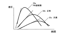
FIG. 3 is a graph showing the difference in the transition of the DPF differential pressure according to the state of the
グラフ33aは、PMの堆積量が多く、DPF内にPMが詰まっている状態(以下「過堆積状態」という)におけるDPF差圧を示す。過堆積状態33aでは、正常時33bに比べてDPF17内で排気ガスが流れにくくなるので、DPF差圧は大きくなる。これに応じて、変化量βも大きくなる。
The
グラフ33cは、DPFに欠損などが生じている状態(以下「欠損状態」という)におけるDPF差圧を示す。欠損状態33cでは、正常時33bに比べてDPF17内で排気ガスが流れやすいので、DPF差圧は小さくなる。これに応じて、変化量βも小さくなる。
The graph 33c shows the DPF differential pressure in a state where the DPF is deficient or the like (hereinafter referred to as “deficient state”). In the deficient state 33c, the exhaust gas tends to flow in the
このように、DPF差圧の変化量βは、DPFの状態に応じて異なるという特徴がある。 Thus, there is a feature that the change amount β of the DPF differential pressure varies depending on the state of the DPF.
ここで、インマニ圧の変化量αとDPF差圧の変化量βとの比γ=α/βをとり、このγについて考察する。DPF17が欠損状態である場合には、βが小さくなるのでγの分母が小さくなり、γの値は増大する。一方、DPFが詰まり状態である場合には、βは大きくなるのでγの分母が大きくなり、γの値は小さくなる。
Here, the ratio γ = α / β between the change amount α of the intake manifold pressure and the change amount β of the DPF differential pressure is taken, and this γ is considered. When
図4に示すように、DPF17の欠損状態、正常状態、および過堆積状態において、γはそれぞれ異なる領域に含まれるという特徴がある。したがって、適切な判定値を設定することにより、DPF17の状態を欠損状態、正常状態、および過堆積状態に切り分けることが可能である。例えば、図4を参照すると、第1の判定値γaによって、DPF17の欠損状態が、その他の状態から切り分けられるので、DPF17の故障状態を判別することができる。また、第2の判定値γbによって、DPF17の過堆積状態が、その他の状態から切り分けられるので、DPF17がPMを許容量以上堆積していることを判別することができる。
As shown in FIG. 4, in the deficient state, normal state, and overdeposition state of
本実施形態では、エンジンの加速時において、インマニ圧の変化量αとDPF差圧の変化量βとの比γのとる値に基づいて、DPF17の状態を判別する。
In the present embodiment, the state of the
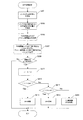
図5は、本実施形態によるDPF17の状態を検知する処理のフローチャートである。
FIG. 5 is a flowchart of processing for detecting the state of the
ステップS101において、インマニ圧およびDPF差圧が計測される。インマニ圧31は、吸気管21内に設置された圧力センサ23によって計測され、DPF差圧33は、DPF17の上流および下流に接続される差圧センサ19によって計測される。
In step S101, the intake manifold pressure and the DPF differential pressure are measured. The intake manifold pressure 31 is measured by a
ステップS103において、インマニ圧の変化量αが式(1)で算出され、DPF差圧の変化量βが式(2)で算出される。このとき、式(2)で用いるインマニ圧およびDPF差圧の時間差Δtは、圧力センサおよび差圧センサの間の位置関係と、吸気または排気流量とに応じて適宜決められる。 In step S103, the change amount α of the intake manifold pressure is calculated by the equation (1), and the change amount β of the DPF differential pressure is calculated by the equation (2). At this time, the time difference Δt between the intake manifold pressure and the DPF differential pressure used in Expression (2) is appropriately determined according to the positional relationship between the pressure sensor and the differential pressure sensor and the intake or exhaust flow rate.
ステップS105において、インマニ圧の変化量αが所定値以上かどうかが確認される。所定値以上のときは、エンジンが過渡運転状態であると判定されステップS107へ進む。所定値以下のときは、処理を終了する。 In step S105, it is confirmed whether the change amount α of the intake manifold pressure is equal to or greater than a predetermined value. When it is equal to or greater than the predetermined value, it is determined that the engine is in a transient operation state, and the process proceeds to step S107. When it is less than the predetermined value, the process is terminated.
ステップS107において、インマニ圧の変化量αとDPF差圧の変化量βとの比γ=α/βが算出される。 In step S107, the ratio γ = α / β between the variation amount α of the intake manifold pressure and the variation amount β of the DPF differential pressure is calculated.
ステップS109において、γが所定の第1の判定値γaより大きいかどうかが確認される。γがγaより大きいときには、ステップS111に進み、DPF故障と判定される。γがγa以下のときには、ステップS113に進む。 In step S109, it is confirmed whether γ is greater than a predetermined first determination value γa. When γ is larger than γa, the process proceeds to step S111, and it is determined that the DPF has failed. When γ is γa or less, the process proceeds to step S113.
ステップS113において、γが所定の判定値γbより大きいかどうかが確認される。γがγbより大きいときには、ステップS115に進み、DPF正常と判定される。γがγb以下のときには、ステップS117に進み、DPF過堆積と判定され、再生処理が実行される。 In step S113, it is confirmed whether γ is larger than a predetermined determination value γb. When γ is larger than γb, the process proceeds to step S115 and it is determined that the DPF is normal. When γ is equal to or less than γb, the process proceeds to step S117, where it is determined that the DPF is excessively deposited, and the regeneration process is executed.
このように、本実施形態は、エンジンの加速時にDPFの状態検知を実施する。加速時のようなエンジンの過渡運転状態は、運転中頻繁に生じるので、本発明によるDPFの状態検知手法は、DPFの状態検知を運転中に頻繁に実施することが可能である。 Thus, this embodiment implements DPF state detection during engine acceleration. Since the transient operation state of the engine, such as during acceleration, frequently occurs during operation, the DPF state detection method according to the present invention can frequently detect the DPF state during operation.
次に、本発明の第2の実施形態について説明する。 Next, a second embodiment of the present invention will be described.
本実施形態によるDPFの状態検知手法は、基本的な概念は第1の実施形態と同じであるが、状態判別を行う判定値の決め方が異なる。 The basic concept of the DPF state detection method according to the present embodiment is the same as that of the first embodiment, but the determination method for determining the state is different.
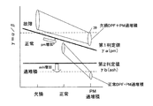
図6は、本実施形態における第1の判定値γa(pm)および第2の判定値γb(ash)を示す図である。図4を参照して先に説明したように、インマニ圧の変化量αとDPF差圧の変化量βとの比γ=α/βによって、DPFの状態を検知することができる。しかし、たとえば図6の符号39で示す領域のように、過堆積状態において欠損などの故障が発生した場合、DPF内では、正常状態と同じように排気ガスが流れやすくなるわけではなく、γの値も正常状態に比べて大きくならない状況が考えられる。この場合、第1の判定値γaが定数に設定されると、DPF17の故障状態が判別されない可能性がある。
FIG. 6 is a diagram illustrating the first determination value γa (pm) and the second determination value γb (ash) in the present embodiment. As described above with reference to FIG. 4, the state of the DPF can be detected by the ratio γ = α / β of the change amount α of the intake manifold pressure and the change amount β of the DPF differential pressure. However, when a failure such as a defect occurs in the over-deposited state, for example, in the region indicated by
そこで、本実施形態では、DPFの故障判別に用いる第1の判定値を、PM堆積量pmに応じて変化する関数γa(pm)とする。第1の判定値γa(pm)は、図6に示すように、PM堆積量pmが増加するにつれて小さな値をとるように設定される。 Therefore, in the present embodiment, the first determination value used for determining the DPF failure is a function γa (pm) that changes according to the PM accumulation amount pm. As shown in FIG. 6, the first determination value γa (pm) is set to take a smaller value as the PM deposition amount pm increases.
また、DPFの再生処理の後、DPF内には排気中のオイル成分などの燃え残り(アッシュ)が残留する。アッシュは、再生処理を繰り返すたびにDPF内に堆積されていく。本実施形態でDPFの状態判別に用いるDPF差圧の変化量βは、PMの他にアッシュの残留量の影響も受ける。つまり、アッシュの残留量が増えると、同一のPM堆積量に対応するDPF差圧の変化量βは、より大きな値をとるようになるので、γ=α/βはより小さい値をとるようになる。第2の判定値γbが定数に設定されると、未だ再生処理を行うほどPMがDPF内に堆積していないにもかかわらず、アッシュ残留量の影響によってDPFの過堆積状態が誤って判別される可能性がある。 In addition, after the DPF regeneration process, unburned residue (ash) such as oil components in the exhaust gas remains in the DPF. Ashes are deposited in the DPF every time the regeneration process is repeated. The change amount β of the DPF differential pressure used for determining the state of the DPF in this embodiment is also affected by the residual amount of ash in addition to PM. That is, as the residual amount of ash increases, the change amount β of the DPF differential pressure corresponding to the same PM accumulation amount takes a larger value, so that γ = α / β takes a smaller value. Become. When the second determination value γb is set to a constant, the DPF overdeposition state is erroneously determined due to the influence of the residual amount of ash even though the PM has not yet accumulated in the DPF so as to perform the regeneration process. There is a possibility.
そこで、本実施形態では、DPFの過堆積を判定する第2の判定値を、アッシュの残留量ashに応じて変化する関数γb(ash)とする。第2の判定値γb(ash)は、図6に示すように、アッシュ残留量ashが増加するにつれて小さな値をとるように設定される。 Therefore, in the present embodiment, the second determination value for determining DPF overdeposition is a function γb (ash) that changes in accordance with the residual ash amount ash. As shown in FIG. 6, the second determination value γb (ash) is set to take a smaller value as the ash residual amount ash increases.
図7は、本実施形態によるDPF状態検知処理のフローチャートである。 FIG. 7 is a flowchart of the DPF state detection process according to the present embodiment.
ステップS201において、インマニ圧およびDPF差圧が計測される。インマニ圧31は、吸気管21内に設置された圧力センサ23によって計測され、DPF差圧33は、DPF17の上流および下流に接続される差圧センサ19によって計測される。
In step S201, the intake manifold pressure and the DPF differential pressure are measured. The intake manifold pressure 31 is measured by a
ステップS203において、インマニ圧の変化量αが式(1)で算出され、DPF差圧の変化量βが式(2)で算出される。このとき、式(2)で用いるインマニ圧およびDPF差圧の時間差Δtは、圧力センサおよび差圧センサの間の位置関係と、吸気または排気流量とに応じて適宜決められる。 In step S203, the change amount α of the intake manifold pressure is calculated by the equation (1), and the change amount β of the DPF differential pressure is calculated by the equation (2). At this time, the time difference Δt between the intake manifold pressure and the DPF differential pressure used in Expression (2) is appropriately determined according to the positional relationship between the pressure sensor and the differential pressure sensor and the intake or exhaust flow rate.
ステップS205において、DPFのPM堆積量pmおよびアッシュ残留量ashが推定される。PM堆積量pmは、たとえば特許文献2に記載されているような周知の手法を利用して、インマニ圧やDPF差圧などに基づいて算出される。アッシュ残留量ashは、たとえば、再生処理を実施した直後のDPF差圧に基づいて算出される。また、アッシュ残留量ashは、再生処理を実施した直後のインマニ圧の変化量αおよびDPF差圧の変化量βの比γと、新品相当のDPFのγとの差分Δγに基づいて算出されてもよい。アッシュ残留量ashは、再生処理が実施される度に算出され、メモリ13cに記憶されている。
In step S205, the PM accumulation amount pm and the ash residual amount ash of the DPF are estimated. The PM deposition amount pm is calculated based on the intake manifold pressure, the DPF differential pressure, or the like using a known method as described in Patent Document 2, for example. The ash residual amount ash is calculated based on, for example, the DPF differential pressure immediately after the regeneration process is performed. The ash residual amount ash is calculated based on the difference Δγ between the ratio γ of the intake manifold pressure change α and the DPF differential pressure change β immediately after the regeneration process and the DPF γ corresponding to a new product. Also good. The ash residual amount ash is calculated every time the reproduction process is performed, and is stored in the
ステップS207において、推定したPM堆積量pmに応じて、第1の判定値γa(pm)が設定され、推定したアッシュ残留量ashに応じて、第2の判定値γb(ash)が設定される。 In step S207, the first determination value γa (pm) is set according to the estimated PM accumulation amount pm, and the second determination value γb (ash) is set according to the estimated ash residual amount ash. .
ステップS209において、インマニ圧の変化量αが所定値以上かどうかが確認される。所定値以上のときは、エンジンが過渡運転状態であると判定されステップS211へ進む。所定値以下のときは、処理を終了する。 In step S209, it is confirmed whether the intake manifold pressure change amount α is greater than or equal to a predetermined value. When it is equal to or greater than the predetermined value, it is determined that the engine is in a transient operation state, and the process proceeds to step S211. When it is less than the predetermined value, the process is terminated.
ステップS211において、インマニ圧の変化量αとDPF差圧の変化量βの比γ=α/βが算出される。 In step S211, a ratio γ = α / β of the intake manifold pressure change amount α and the DPF differential pressure change amount β is calculated.
ステップS213において、γが第1の判定値γa(pm)より大きいかどうかが確認される。γがγa(pm)より大きいときには、ステップS215に進み、DPF故障と判定される。γがγa(pm)以下のときには、ステップS217に進む。 In step S213, it is confirmed whether γ is larger than the first determination value γa (pm). When γ is larger than γa (pm), the process proceeds to step S215, and it is determined that the DPF has failed. When γ is γa (pm) or less, the process proceeds to step S217.
ステップS217において、γが第2の判定値γb(ash)より大きいかどうかが確認される。γがγb(ash)より大きいときには、ステップS219に進み、DPF正常と判定される。γがγb(ash)以下のときには、ステップS221に進み、DPF過堆積と判定され、再生処理が実行される。 In step S217, it is confirmed whether γ is larger than the second determination value γb (ash). When γ is larger than γb (ash), the process proceeds to step S219, and it is determined that the DPF is normal. When γ is equal to or less than γb (ash), the process proceeds to step S221, where it is determined that the DPF is excessively deposited, and the regeneration process is executed.
このように、本実施形態では、DPF内のPM堆積量およびアッシュ残留量に応じて判定値を変更するので、DPF内にPMやアッシュが多く堆積している状態でも、精度良くDPFの状態検出を行うことが可能である。 As described above, in this embodiment, since the determination value is changed according to the PM accumulation amount and the ash residual amount in the DPF, the state of the DPF is accurately detected even when a large amount of PM or ash is accumulated in the DPF. Can be done.
次に、本発明の第3の実施形態について説明する。 Next, a third embodiment of the present invention will be described.
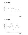
図8は、DPF正常時および故障時における、DPF状態検知処理の1周期ごとに算出されるγの値の推移を示す図である。図8(a)に示すように、DPF正常時には、γは各周期間で大差なく推移している。一方、図8(b)に示すように、DPF故障時には、欠損の影響によりDPF内の排気ガスの流れが不安定であるため、DPF差圧の変化量βも不安定となる。このためDPF故障時には、処理ループごとに算出されるγのばらつきが大きくなるという特徴がある。 FIG. 8 is a diagram illustrating a transition of the value of γ calculated for each cycle of the DPF state detection process when the DPF is normal and when the failure occurs. As shown in FIG. 8A, when the DPF is normal, γ changes with no significant difference between the periods. On the other hand, as shown in FIG. 8 (b), when the DPF fails, the flow of exhaust gas in the DPF is unstable due to the deficiency, so that the change amount β of the DPF differential pressure also becomes unstable. For this reason, there is a feature that variation of γ calculated for each processing loop becomes large at the time of DPF failure.
本実施形態では、γの今回値と前回値の差分を所定回数分積算し、この積算値が所定の判定値を超えたときにDPFの状態検知を行う。この積算値は、γのばらつきの度合いを表しており、積算値が大きいほどγのばらつきが大きいことを示す。 In the present embodiment, the difference between the current value of γ and the previous value is integrated a predetermined number of times, and the DPF state is detected when the integrated value exceeds a predetermined determination value. This integrated value represents the degree of variation in γ, and the larger the integrated value, the larger the variation in γ.
図9は、本実施形態によるDPF状態検知処理のフローチャートである。 FIG. 9 is a flowchart of the DPF state detection process according to the present embodiment.
ステップS301において、インマニ圧およびDPF差圧が計測される。インマニ圧31は、吸気管21内に設置された圧力センサ23によって計測され、DPF差圧33は、DPF17の上流および下流に接続される差圧センサ19によって計測される。
In step S301, the intake manifold pressure and the DPF differential pressure are measured. The intake manifold pressure 31 is measured by a
ステップS303において、インマニ圧の変化量αが式(1)で算出され、DPF差圧の変化量βが式(2)で算出される。このとき、式(2)で用いるインマニ圧およびDPF差圧の時間差Δtは、圧力センサおよび差圧センサの間の位置関係と、吸気または排気流量とに応じて適宜決められる。 In step S303, the change amount α of the intake manifold pressure is calculated by the equation (1), and the change amount β of the DPF differential pressure is calculated by the equation (2). At this time, the time difference Δt between the intake manifold pressure and the DPF differential pressure used in Expression (2) is appropriately determined according to the positional relationship between the pressure sensor and the differential pressure sensor and the intake or exhaust flow rate.
ステップS305において、インマニ圧の変化量αが所定値以上かどうかが確認される。所定値以上のときは、エンジンが過渡運転状態であると判定されステップS307へ進む。所定値以下のときは、処理を終了する。 In step S305, it is confirmed whether the intake manifold pressure change amount α is greater than or equal to a predetermined value. When the value is equal to or greater than the predetermined value, it is determined that the engine is in a transient operation state, and the process proceeds to step S307. When it is less than the predetermined value, the process is terminated.
ステップS307において、インマニ圧の変化量αとDPF差圧の変化量βの比γ(t)=α/βが算出される。 In step S307, the ratio γ (t) = α / β of the intake manifold pressure change amount α and the DPF differential pressure change amount β is calculated.
ステップS309において、γの今回値γ(t)と前回値γ(t−1)の差分Δγ=γ(t)―γ(t−1)が算出される。 In step S309, the difference Δγ = γ (t) −γ (t−1) between the current value γ (t) of γ and the previous value γ (t−1) is calculated.
ステップS311において、この差分Δγの所定回数分の二乗和ΣΔγ2が所定の判定値より大きいかどうかが確認される。二乗和ΣΔγ2が判定値より大きいときには、ステップS313に進み、DPF故障と判定される。判定値以下のときには、ステップS315に進み、DPF正常と判定される。 In step S311, whether the square sum Shigumaderutaganma 2 of a predetermined number of times of the difference Δγ is larger than a predetermined judgment value is confirmed. When the square sum Shigumaderutaganma 2 is greater than the determination value, the process proceeds to step S313, it is determined that the DPF failure. When it is equal to or smaller than the determination value, the process proceeds to step S315, and it is determined that the DPF is normal.
以上、本発明の具体的な実施例について説明した。しかし、本発明はこのような実施例に限定されるものではない。 The specific embodiments of the present invention have been described above. However, the present invention is not limited to such examples.
上述の実施形態では、DPFの状態判別にインマニ圧を利用したが、排気流量に相関のある信号であれば良い。たとえばDPF上流側の排気管内圧力を用いても本発明は実施可能であり、吸気流量または排気流量を直接計測して利用しても良い。 In the above-described embodiment, the intake manifold pressure is used to determine the state of the DPF, but any signal having a correlation with the exhaust flow rate may be used. For example, the present invention can be implemented even if the pressure in the exhaust pipe upstream of the DPF is used, and the intake flow rate or the exhaust flow rate may be directly measured and used.
また、上述の実施形態では、DPF102の状態検知を行う過渡状態としてエンジンの加速時を例示したが、エンジンの減速時でも本発明は実施することができる。 In the above-described embodiment, the engine acceleration is exemplified as the transient state in which the state of the DPF 102 is detected. However, the present invention can be implemented even when the engine is decelerated.
また、上述の実施形態では、ディーゼルエンジンについて説明したが、ガソリンエンジンでも同様に本発明を適用可能である。 Moreover, although the diesel engine was demonstrated in the above-mentioned embodiment, this invention is applicable similarly also with a gasoline engine.
13 電子制御ユニット(ECU)
17 ディーゼル・パティキュレート・フィルタ(DPF)
19 差圧センサ
23 圧力センサ
13 Electronic control unit (ECU)
17 Diesel particulate filter (DPF)
19
Claims (5)
内燃機関の排気流量に相関のある信号を検出する排気流量検出手段と、
前記パティキュレートフィルタの前後差圧を検出する差圧検出手段と、
前記内燃機関の過渡時において、前記排気流量に相関のある信号の変化量と前記差圧の変化量との比を所定のしきい値と比較して、前記パティキュレートフィルタの状態を判定する状態判定手段と、
を有する、内燃機関のパティキュレートフィルタの状態検知装置。 A particulate filter provided in an exhaust system of an internal combustion engine;
An exhaust flow rate detecting means for detecting a signal correlated with the exhaust flow rate of the internal combustion engine;
Differential pressure detecting means for detecting a differential pressure across the particulate filter;
A state in which the state of the particulate filter is determined by comparing a ratio of the change amount of the signal correlated with the exhaust flow rate and the change amount of the differential pressure with a predetermined threshold value during the transition of the internal combustion engine. A determination means;
A state detection device for a particulate filter of an internal combustion engine, comprising:
前記排気流量に相関のある信号の変化量と前記差圧の変化量との比を第2のしきい値と比較して、前記パティキュレートフィルタ中のパティキュレートが過堆積であると判定する、請求項1に記載のパティキュレートフィルタの状態検知装置。 The state determining means compares the ratio of the amount of change in the signal correlated with the exhaust flow rate and the amount of change in the differential pressure with a first threshold value to determine whether the particulate filter has failed,
A ratio of a change amount of a signal correlated with the exhaust flow rate and a change amount of the differential pressure is compared with a second threshold value to determine that the particulates in the particulate filter are over-deposited; The particulate filter state detection device according to claim 1.
Priority Applications (4)
| Application Number | Priority Date | Filing Date | Title |
|---|---|---|---|
| JP2006123168A JP4762043B2 (en) | 2006-04-27 | 2006-04-27 | Particulate filter state detection device |
| EP07008459A EP1849972B1 (en) | 2006-04-27 | 2007-04-25 | An apparatus for detecting a state of a particulate filter |
| DE602007000060T DE602007000060D1 (en) | 2006-04-27 | 2007-04-25 | Device for determining the state of a particle filter |
| US11/790,694 US7797926B2 (en) | 2006-04-27 | 2007-04-26 | Apparatus for detecting a state of a particulate filter |
Applications Claiming Priority (1)
| Application Number | Priority Date | Filing Date | Title |
|---|---|---|---|
| JP2006123168A JP4762043B2 (en) | 2006-04-27 | 2006-04-27 | Particulate filter state detection device |
Publications (2)
| Publication Number | Publication Date |
|---|---|
| JP2007292013A true JP2007292013A (en) | 2007-11-08 |
| JP4762043B2 JP4762043B2 (en) | 2011-08-31 |
Family
ID=38234962
Family Applications (1)
| Application Number | Title | Priority Date | Filing Date |
|---|---|---|---|
| JP2006123168A Expired - Fee Related JP4762043B2 (en) | 2006-04-27 | 2006-04-27 | Particulate filter state detection device |
Country Status (4)
| Country | Link |
|---|---|
| US (1) | US7797926B2 (en) |
| EP (1) | EP1849972B1 (en) |
| JP (1) | JP4762043B2 (en) |
| DE (1) | DE602007000060D1 (en) |
Cited By (10)
| Publication number | Priority date | Publication date | Assignee | Title |
|---|---|---|---|---|
| WO2009101667A1 (en) * | 2008-02-14 | 2009-08-20 | Honda Motor Co., Ltd. | Exhaust gas collecting performance judging method and device therefor |
| JP2011208629A (en) * | 2010-03-26 | 2011-10-20 | Ford Global Technologies Llc | Method and system for diagnosing multiple cylinder engine |
| EP2733323A1 (en) | 2012-11-15 | 2014-05-21 | Toyota Jidosha Kabushiki Kaisha | Filter abnormality determining device |
| WO2014087536A1 (en) | 2012-12-07 | 2014-06-12 | トヨタ自動車株式会社 | Device for detecting fault in exhaust gas purifier |
| EP3061937A1 (en) | 2015-02-26 | 2016-08-31 | Toyota Jidosha Kabushiki Kaisha | Abnormality determination system for an exhaust device |
| JP2020033943A (en) * | 2018-08-30 | 2020-03-05 | 株式会社豊田自動織機 | Filter abnormal condition determination apparatus |
| JP2020139466A (en) * | 2019-02-28 | 2020-09-03 | トヨタ自動車株式会社 | Internal combustion engine control device |
| CN111819345A (en) * | 2018-03-13 | 2020-10-23 | 雷诺股份公司 | Method and apparatus for determining the presence and operation of a particulate filter |
| WO2023149285A1 (en) * | 2022-02-02 | 2023-08-10 | コベルコ建機株式会社 | Diagnostic device for exhaust gas aftertreatment device, diagnostic method for exhaust gas aftertreatment device, and diagnostic program for exhaust gas aftertreatment device |
| JPWO2023233605A1 (en) * | 2022-06-02 | 2023-12-07 |
Families Citing this family (41)
| Publication number | Priority date | Publication date | Assignee | Title |
|---|---|---|---|---|
| DE102007003153B4 (en) * | 2007-01-22 | 2011-01-05 | Continental Automotive Gmbh | Method for checking the plausibility of a determined differential pressure value via a particle filter |
| US7698888B2 (en) * | 2007-02-06 | 2010-04-20 | International Engine Intellectual Property Company, Llc | System and method for calculating loading of a diesel particulate filter by windowing inputs |
| JP4430704B2 (en) * | 2007-10-01 | 2010-03-10 | 本田技研工業株式会社 | Exhaust gas purification device for internal combustion engine |
| US8182578B2 (en) * | 2007-11-30 | 2012-05-22 | Caterpillar Inc. | Engine exhaust after-treatment system |
| JP2009138704A (en) * | 2007-12-10 | 2009-06-25 | Mitsubishi Fuso Truck & Bus Corp | Exhaust emission aftertreatment device |
| FR2926846B1 (en) * | 2008-01-28 | 2013-01-18 | Renault Sas | DEVICE AND METHOD FOR DIAGNOSING A PARTICLE FILTER FOR A COMBUSTION ENGINE. |
| AT508433B1 (en) * | 2008-08-01 | 2015-12-15 | Steinbauer Electronics Dev Gmbh | METHOD FOR CONTROLLING A DEVICE WITH A COMBUSTION ENGINE AND DEVICE WITH A COMBUSTION ENGINE |
| US20100031637A1 (en) * | 2008-08-06 | 2010-02-11 | Ford Global Technologies, Llc | Rapid heater for emission control device |
| US8091414B2 (en) * | 2008-08-14 | 2012-01-10 | Cummins Filtration Ip, Inc. | Methods of detecting replacement of a particulate matter filter |
| JP2010222993A (en) * | 2009-03-19 | 2010-10-07 | Yanmar Co Ltd | Exhaust emission control device for internal combustion engine |
| JP4852127B2 (en) * | 2009-06-25 | 2012-01-11 | 日立建機株式会社 | Work machine |
| US8096171B2 (en) * | 2009-11-05 | 2012-01-17 | Daimler Ag | Diagnostic method for an internal combustion engine exhaust gas system that includes a particle filter |
| US8146352B2 (en) * | 2010-05-12 | 2012-04-03 | Ford Global Technologies, Llc | Diesel particulate filter control |
| JP5556388B2 (en) * | 2010-06-01 | 2014-07-23 | トヨタ自動車株式会社 | Particulate filter diagnostic device |
| US8660741B2 (en) * | 2010-10-01 | 2014-02-25 | Deere & Company | Particulate filter ash loading prediction method and vehicle with same |
| US8447461B2 (en) * | 2010-10-01 | 2013-05-21 | Deere & Company | Particulate filter ash loading prediction method and vehicle with same |
| US8214135B2 (en) | 2010-10-01 | 2012-07-03 | Deere & Company | Particulate filter ash loading prediction method and vehicle using same |
| US8577541B2 (en) | 2010-10-01 | 2013-11-05 | Deere & Company | Particulate filter ash loading prediction method and vehicle using same |
| US8620597B2 (en) | 2010-10-01 | 2013-12-31 | Deere & Company | Particulate filter service life prediction |
| WO2012053097A1 (en) * | 2010-10-22 | 2012-04-26 | トヨタ自動車株式会社 | Filter failure detection device for internal combustion engine |
| GB2496876B (en) * | 2011-11-24 | 2017-12-06 | Ford Global Tech Llc | Detection of soot burn in a vehicle |
| US9322357B2 (en) * | 2012-01-31 | 2016-04-26 | International Engine Intellectual Property Company, Llc | Soot accumulation model for setpoint modification |
| US8832957B2 (en) | 2012-07-26 | 2014-09-16 | Caterpillar Inc. | Apparatus and method for determining ash height in a filter |
| US9091190B2 (en) * | 2012-08-01 | 2015-07-28 | GM Global Technology Operations LLC | Accumulated ash correction during soot mass estimation in a vehicle exhaust aftertreatment device |
| US9303579B2 (en) * | 2012-08-01 | 2016-04-05 | GM Global Technology Operations LLC | System and method for monitoring a particulate filter in a vehicle exhaust aftertreatment device |
| US9708960B2 (en) * | 2013-05-08 | 2017-07-18 | Cummins Ip, Inc. | Exhaust aftertreatment system diagnostic and conditioning |
| US8935953B2 (en) * | 2013-05-15 | 2015-01-20 | GM Global Technology Operations LLC | Adaptive soot mass estimation in a vehicle exhaust after-treatment device |
| US9574714B2 (en) * | 2013-07-29 | 2017-02-21 | Nordson Corporation | Adhesive melter and method having predictive maintenance for exhaust air filter |
| KR20150111266A (en) * | 2014-02-26 | 2015-10-05 | 가부시키가이샤 고마쓰 세이사쿠쇼 | Malfunction-determining device for exhaust gas purifying device and malfunction-determining method for exhaust gas purifying device |
| DE102014206252B4 (en) | 2014-04-02 | 2016-05-12 | Continental Automotive Gmbh | Method and device for diagnosing the functionality of a diesel particulate filter |
| DE102015211151B4 (en) * | 2015-06-17 | 2021-08-12 | Vitesco Technologies GmbH | Method and device for determining the loading state of an exhaust gas particle filter |
| DE102015014931B4 (en) * | 2015-11-18 | 2021-01-07 | Audi Ag | Method for monitoring a condition of a device |
| US10823593B2 (en) * | 2018-03-09 | 2020-11-03 | Sensors, Inc. | Engine exhaust flow measurement with pulsation compensation |
| US11333056B2 (en) | 2019-07-15 | 2022-05-17 | Fca Us Llc | Gasoline particulate filter brick detection techniques |
| CN113374565B (en) * | 2021-06-28 | 2022-08-30 | 东风汽车有限公司东风日产乘用车公司 | Vehicle particle trap system fault diagnosis method, storage medium and electronic device |
| CN114252274B (en) * | 2021-12-13 | 2024-07-16 | 中国船舶重工集团公司第七0三研究所 | On-line detection method for blockage of gas turbine inlet filter |
| CN115013131B (en) * | 2022-07-26 | 2023-11-17 | 潍柴动力股份有限公司 | DPF state monitoring method and device and vehicle |
| CN115614136B (en) * | 2022-10-31 | 2025-06-06 | 湖南道依茨动力有限公司 | DPF low efficiency fault diagnosis method, device and operating machinery |
| CN117167123B (en) * | 2023-09-28 | 2026-03-20 | 潍柴动力股份有限公司 | A method, apparatus and equipment for DPF cryogenic active regeneration control |
| CN118481793B (en) * | 2024-05-11 | 2025-12-19 | 潍柴动力股份有限公司 | Jam detection method, device, equipment and storage medium |
| CN118706478B (en) * | 2024-08-28 | 2024-12-13 | 江西五十铃汽车有限公司 | A post-processing high mileage degradation evaluation method, system, storage medium and device |
Citations (3)
| Publication number | Priority date | Publication date | Assignee | Title |
|---|---|---|---|---|
| JP2003166411A (en) * | 2001-11-29 | 2003-06-13 | Toyota Motor Corp | Exhaust purification device for internal combustion engine |
| JP2004044443A (en) * | 2002-07-10 | 2004-02-12 | Toyota Motor Corp | Exhaust gas purification device |
| JP2005351249A (en) * | 2004-06-14 | 2005-12-22 | Toyota Motor Corp | Filter clogging detection device |
Family Cites Families (11)
| Publication number | Priority date | Publication date | Assignee | Title |
|---|---|---|---|---|
| JPS57159519A (en) | 1981-03-30 | 1982-10-01 | Nippon Soken Inc | Detection of clogging degree of fine particle collecting member |
| JPH05240026A (en) * | 1992-02-28 | 1993-09-17 | Tonen Corp | Exhaust gas purification device for diesel engine |
| JP3598573B2 (en) | 1995-04-14 | 2004-12-08 | 株式会社デンソー | Exhaust particulate purification equipment |
| JP3887903B2 (en) * | 1997-09-02 | 2007-02-28 | 株式会社デンソー | Air-fuel ratio control device for internal combustion engine |
| US6497095B2 (en) * | 2000-12-21 | 2002-12-24 | Ford Global Technologies, Inc. | Regeneration of diesel engine particulate filter only above low fuel levels |
| JP3922107B2 (en) * | 2002-06-14 | 2007-05-30 | 株式会社デンソー | Exhaust gas purification device for internal combustion engine |
| JP4042476B2 (en) * | 2002-06-14 | 2008-02-06 | 株式会社デンソー | Exhaust gas purification device for internal combustion engine |
| JP3864910B2 (en) * | 2003-01-10 | 2007-01-10 | 日産自動車株式会社 | Exhaust gas purification device for internal combustion engine |
| JP4103719B2 (en) * | 2003-07-31 | 2008-06-18 | 日産自動車株式会社 | ENGINE EXHAUST PURIFICATION APPARATUS AND METHOD FOR DETERMINING PARTICLE DEPOSITION STATE OF PARTICLE COLLECTION FILTER |
| JP4470593B2 (en) * | 2004-06-03 | 2010-06-02 | 株式会社デンソー | Exhaust gas purification device for internal combustion engine |
| US7677032B2 (en) * | 2005-09-15 | 2010-03-16 | Cummins, Inc. | Apparatus, system, and method for determining the distribution of particulate matter on a particulate filter |
-
2006
- 2006-04-27 JP JP2006123168A patent/JP4762043B2/en not_active Expired - Fee Related
-
2007
- 2007-04-25 EP EP07008459A patent/EP1849972B1/en not_active Ceased
- 2007-04-25 DE DE602007000060T patent/DE602007000060D1/en active Active
- 2007-04-26 US US11/790,694 patent/US7797926B2/en not_active Expired - Fee Related
Patent Citations (3)
| Publication number | Priority date | Publication date | Assignee | Title |
|---|---|---|---|---|
| JP2003166411A (en) * | 2001-11-29 | 2003-06-13 | Toyota Motor Corp | Exhaust purification device for internal combustion engine |
| JP2004044443A (en) * | 2002-07-10 | 2004-02-12 | Toyota Motor Corp | Exhaust gas purification device |
| JP2005351249A (en) * | 2004-06-14 | 2005-12-22 | Toyota Motor Corp | Filter clogging detection device |
Cited By (21)
| Publication number | Priority date | Publication date | Assignee | Title |
|---|---|---|---|---|
| WO2009101667A1 (en) * | 2008-02-14 | 2009-08-20 | Honda Motor Co., Ltd. | Exhaust gas collecting performance judging method and device therefor |
| JP2009216077A (en) * | 2008-02-14 | 2009-09-24 | Honda Motor Co Ltd | Exhaust gas collecting performance judging device |
| EP2261474A4 (en) * | 2008-02-14 | 2011-05-25 | Honda Motor Co Ltd | Exhaust gas collecting performance judging method and device therefor |
| JP2011208629A (en) * | 2010-03-26 | 2011-10-20 | Ford Global Technologies Llc | Method and system for diagnosing multiple cylinder engine |
| EP2733323A1 (en) | 2012-11-15 | 2014-05-21 | Toyota Jidosha Kabushiki Kaisha | Filter abnormality determining device |
| WO2014087536A1 (en) | 2012-12-07 | 2014-06-12 | トヨタ自動車株式会社 | Device for detecting fault in exhaust gas purifier |
| US9879586B2 (en) | 2012-12-07 | 2018-01-30 | Toyota Jidosha Kabushiki Kaisha | Abnormality detection device for exhaust gas purification apparatus |
| EP3061937A1 (en) | 2015-02-26 | 2016-08-31 | Toyota Jidosha Kabushiki Kaisha | Abnormality determination system for an exhaust device |
| CN111819345A (en) * | 2018-03-13 | 2020-10-23 | 雷诺股份公司 | Method and apparatus for determining the presence and operation of a particulate filter |
| CN111819345B (en) * | 2018-03-13 | 2022-10-25 | 雷诺股份公司 | Method and apparatus for determining the presence and operation of a particulate filter |
| JP2020033943A (en) * | 2018-08-30 | 2020-03-05 | 株式会社豊田自動織機 | Filter abnormal condition determination apparatus |
| JP7035910B2 (en) | 2018-08-30 | 2022-03-15 | 株式会社豊田自動織機 | Filter abnormality judgment device |
| JP2020139466A (en) * | 2019-02-28 | 2020-09-03 | トヨタ自動車株式会社 | Internal combustion engine control device |
| JP7088079B2 (en) | 2019-02-28 | 2022-06-21 | トヨタ自動車株式会社 | Internal combustion engine control device |
| WO2023149285A1 (en) * | 2022-02-02 | 2023-08-10 | コベルコ建機株式会社 | Diagnostic device for exhaust gas aftertreatment device, diagnostic method for exhaust gas aftertreatment device, and diagnostic program for exhaust gas aftertreatment device |
| JP2023112953A (en) * | 2022-02-02 | 2023-08-15 | コベルコ建機株式会社 | Diagnostic device for exhaust gas after-treatment device, diagnostic method for exhaust gas after-treatment device, and diagnostic program for exhaust gas after-treatment device |
| US12404816B2 (en) | 2022-02-02 | 2025-09-02 | Kobelco Construction Machinery Co., Ltd | Diagnostic device for exhaust gas aftertreatment device, diagnostic method for exhaust gas aftertreatment device, and diagnostic program for exhaust gas aftertreatment device |
| JP7750129B2 (en) | 2022-02-02 | 2025-10-07 | コベルコ建機株式会社 | Diagnostic device for exhaust gas aftertreatment device, diagnostic method for exhaust gas aftertreatment device, and diagnostic program for exhaust gas aftertreatment device |
| JPWO2023233605A1 (en) * | 2022-06-02 | 2023-12-07 | ||
| WO2023233605A1 (en) * | 2022-06-02 | 2023-12-07 | 日産自動車株式会社 | Method and device for detecting pressure difference of particulate filter |
| JP7740542B2 (en) | 2022-06-02 | 2025-09-17 | 日産自動車株式会社 | Particulate filter pressure differential detection method and apparatus |
Also Published As
| Publication number | Publication date |
|---|---|
| US20070251214A1 (en) | 2007-11-01 |
| EP1849972B1 (en) | 2008-08-06 |
| EP1849972A1 (en) | 2007-10-31 |
| US7797926B2 (en) | 2010-09-21 |
| DE602007000060D1 (en) | 2008-09-18 |
| JP4762043B2 (en) | 2011-08-31 |
Similar Documents
| Publication | Publication Date | Title |
|---|---|---|
| JP4762043B2 (en) | Particulate filter state detection device | |
| JP3922107B2 (en) | Exhaust gas purification device for internal combustion engine | |
| US6907873B2 (en) | Filter control method and device | |
| US10408114B2 (en) | Gasoline particulate filter diagnostics | |
| JP5344084B2 (en) | Particulate filter failure detection apparatus and failure detection method | |
| CN101896699B (en) | Exhaust aftertreatment device | |
| US7578123B2 (en) | Exhaust cleaning device of diesel engine | |
| JP5088391B2 (en) | Particulate filter failure determination device | |
| CN103314191B (en) | The Fail detecting apparatus of particulate filter | |
| JP4335531B2 (en) | Method and apparatus for monitoring signals | |
| US20040211159A1 (en) | Exhaust gas cleaner | |
| EP2459855B1 (en) | Abnormality detection apparatus for particulate filter | |
| JP2009293518A (en) | Exhaust emission control device for internal combustion engine | |
| JP2006291788A (en) | Exhaust gas purification device for internal combustion engine | |
| JP2019218917A (en) | Filter removal detection device | |
| JP3908204B2 (en) | Filter control device | |
| JP4863111B2 (en) | Exhaust purification device | |
| CN100526619C (en) | Exhaust gas control system for internal combustion engine and method for recovering filter thereof | |
| JP4241465B2 (en) | Particulate filter regeneration processing device inspection system | |
| JP7375674B2 (en) | Control devices, internal combustion engine systems and diagnostic methods | |
| JP2005207240A (en) | Particulate filter abnormality judgment device | |
| JP2020051405A (en) | Diagnostic device for internal combustion engine | |
| JP2006274978A (en) | Exhaust emission control device of internal combustion engine | |
| KR100680340B1 (en) | CPU playback control method |
Legal Events
| Date | Code | Title | Description |
|---|---|---|---|
| A621 | Written request for application examination |
Free format text: JAPANESE INTERMEDIATE CODE: A621 Effective date: 20081127 |
|
| A977 | Report on retrieval |
Free format text: JAPANESE INTERMEDIATE CODE: A971007 Effective date: 20101115 |
|
| A131 | Notification of reasons for refusal |
Free format text: JAPANESE INTERMEDIATE CODE: A131 Effective date: 20101124 |
|
| A521 | Written amendment |
Free format text: JAPANESE INTERMEDIATE CODE: A523 Effective date: 20110113 |
|
| TRDD | Decision of grant or rejection written | ||
| A01 | Written decision to grant a patent or to grant a registration (utility model) |
Free format text: JAPANESE INTERMEDIATE CODE: A01 Effective date: 20110607 |
|
| A01 | Written decision to grant a patent or to grant a registration (utility model) |
Free format text: JAPANESE INTERMEDIATE CODE: A01 |
|
| A61 | First payment of annual fees (during grant procedure) |
Free format text: JAPANESE INTERMEDIATE CODE: A61 Effective date: 20110607 |
|
| FPAY | Renewal fee payment (event date is renewal date of database) |
Free format text: PAYMENT UNTIL: 20140617 Year of fee payment: 3 |
|
| R150 | Certificate of patent or registration of utility model |
Free format text: JAPANESE INTERMEDIATE CODE: R150 |
|
| LAPS | Cancellation because of no payment of annual fees |