JP2007288963A - Plug-in power distribution board - Google Patents
Plug-in power distribution board Download PDFInfo
- Publication number
- JP2007288963A JP2007288963A JP2006115480A JP2006115480A JP2007288963A JP 2007288963 A JP2007288963 A JP 2007288963A JP 2006115480 A JP2006115480 A JP 2006115480A JP 2006115480 A JP2006115480 A JP 2006115480A JP 2007288963 A JP2007288963 A JP 2007288963A
- Authority
- JP
- Japan
- Prior art keywords
- pole
- plug
- distribution board
- breaker
- phase module
- Prior art date
- Legal status (The legal status is an assumption and is not a legal conclusion. Google has not performed a legal analysis and makes no representation as to the accuracy of the status listed.)
- Withdrawn
Links
Images


Abstract
Description
本発明は、三相4線式のプラグイン分電盤において3極用ブレーカを使用して三相4線の配線を行うことのできるプラグイン分電盤に関するものである。 The present invention relates to a plug-in distribution board capable of performing three-phase four-wire wiring using a three-pole breaker in a three-phase four-wire plug-in distribution board.
三相4線式の分電盤は、主幹の4極用ブレーカに接続したR、S、T、Nの4本の母線バーの任意の2本又は3本に2極用又は3極用分岐ブレーカの電源側端子と接続することにより単相2線、単相3線、三相3線の電源として負荷に供給することができる(特許文献1参照)ものである。ところが、R、S、T、Nの4本の母線バーから他の三相4線式の分電盤に分岐する場合には4極用ブレーカを介して行うことが一般的である。この場合に送り側の分電盤がプラグイン式の場合には分岐用としてプラグイン式の4極用ブレーカを採用する必要がある。 The three-phase four-wire distribution board is a two-pole or three-pole branch for any two or three of the four bus bars R, S, T, N connected to the main 4-pole breaker By connecting to the power supply side terminal of the breaker, it can be supplied to a load as a single-phase two-wire, single-phase three-wire, or three-phase three-wire power source (see Patent Document 1). However, when branching from the four bus bars of R, S, T, and N to another three-phase four-wire distribution board, it is common to use a four-pole breaker. In this case, when the distribution board on the sending side is a plug-in type, it is necessary to adopt a plug-in type 4-pole breaker for branching.
しかし、4極用ブレーカは、需要が少ないため国内で普及し量産化が進んでいる3極用ブレーカに比べて種類が少ない上、高価である。このような4極用ブレーカを分岐ブレーカとした場合には、非常にコスト高な分電盤となるという問題点がある。
本発明は前記のような従来の問題点を解決して、三相4線式の分電盤において安価に量産されているプラグイン端子金具を備えた3極用ブレーカを使用して三相4線の配線を行うことのできるプラグイン分電盤を提供することである。 The present invention solves the conventional problems as described above and uses a three-phase breaker with a three-pole breaker equipped with a plug-in terminal fitting that is mass-produced inexpensively in a three-phase four-wire distribution board. It is to provide a plug-in distribution board capable of wiring.
本発明のプラグイン分電盤は、電圧極の3本の母線バーに幅方向より接続するプラグ端子金具を備えた3極用ブレーカに隣接させてN極の母線バーに接続するプラグ端子金具を備えたN相モジュールを配置して、電圧極の3本の母線バーとN極の母線バーとよりなる三相4線式の配線を行うことを特徴とするものを基本の発明とする。 The plug-in distribution board of the present invention has a plug terminal fitting connected to an N pole bus bar adjacent to a three pole breaker provided with a plug terminal fitting connected to the three bus bars of the voltage pole from the width direction. The basic invention is characterized by arranging the provided N-phase module and performing three-phase four-wire wiring composed of three bus bars of voltage poles and N-bar bus bars.
この発明において、3極用ブレーカの各プラグ端子金具とN相モジュールのプラグ端子金具をそれぞれの底面に設け、N極の母線バーを電圧極の3本の母線バーの外側に配置してこれにN相モジュールのプラグ端子金具を対応させることが好ましい。また、N相モジュールにハンドルにより操作される断路装置を設けたり、プラグイン分電盤の内部レールに固定されるN相モジュールに、該N相モジュールのプラグ端子金具をN極の母線バーからの接続を解除した状態で保持させる弾性片を設けてもよい。 In the present invention, each plug terminal fitting of the three-pole breaker and the plug terminal fitting of the N-phase module are provided on the respective bottom surfaces, and the N-pole bus bar is disposed outside the three bus bars of the voltage pole. It is preferable to correspond to the plug terminal fitting of the N-phase module. Also, the N-phase module is provided with a disconnect device operated by a handle, or the N-phase module is fixed to the inner rail of the plug-in distribution board, and the plug terminal fitting of the N-phase module is connected to the N pole bus bar. You may provide the elastic piece hold | maintained in the state which cancelled | released the connection.
前記した本発明のプラグイン分電盤は、電圧極の3本の母線バーに幅方向より接続するプラグ端子金具を備えた3極用ブレーカに隣接させてN極の母線バーに接続するプラグ端子金具を備えたN相モジュールを配置したものであるので、電圧極と接続する遮断機能のある3極用ブレーカと特に遮断機能を必要としないN相モジュールとを一組として4極用ブレーカと同様の機能を持つこととなるから、他の三相4線式の分電盤に回路を遮断できるように分岐配線をすることができると共に3極用ブレーカとN相モジュールとを一組として引込電線を接続すれば4極の主幹ブレーカとして使用できるものである。このように、安価に量産できる3極用ブレーカとN相モジュールを採用することにより製造コストを安くできるプラグイン分電盤を提供することができる。 The plug-in distribution board of the present invention described above is a plug terminal connected to an N-pole bus bar adjacent to a 3-pole breaker provided with a plug terminal fitting connected to the three bus bars of the voltage pole from the width direction. Since an N-phase module with metal fittings is arranged, a 3-pole breaker with a blocking function that connects to the voltage pole and an N-phase module that does not particularly require a blocking function are combined as a 4-pole breaker. Therefore, branch wiring can be provided to other three-phase four-wire distribution boards so that the circuit can be cut off, and a three-pole breaker and N-phase module are used as a set. Can be used as a 4-pole main circuit breaker. Thus, the plug-in distribution board which can reduce a manufacturing cost can be provided by employ | adopting the breaker for 3 poles and N-phase module which can be mass-produced cheaply.
また、3極用ブレーカの各プラグ端子金具とN相モジュールのプラグ端子金具をそれぞれの底面に設け、N極の母線バーを電圧極の3本の母線バーの外側に配置してこれにN相モジュールのプラグ端子金具を対応させるものとすると、プラグ端子金具と母線バーとの接続作業が容易であり、また、電圧極の母線バーとN極の母線バーとの識別が容易なものである。 In addition, each of the plug terminal fittings for the three-pole breaker and the plug terminal fitting for the N-phase module are provided on the bottom surface, and the N-pole bus bar is arranged outside the three bus bars of the voltage pole. If the plug terminal fittings of the module are made to correspond to each other, the connection work between the plug terminal fittings and the bus bar is easy, and the discrimination between the voltage pole bus bar and the N pole bus bar is easy.
さらに、N相モジュールにハンドルにより操作される断路装置を設けたり、プラグイン分電盤の内部レールに固定されるN相モジュールに、該N相モジュールのプラグ端子金具をN極の母線バーからの接続を解除した状態で保持させる弾性片を設けることにより、N相モジュールの回路を遮断でき保守・点検時により安全に作業できるものである。 Further, a disconnecting device operated by a handle is provided on the N-phase module, or the plug terminal fitting of the N-phase module is connected to the N-phase module fixed to the internal rail of the plug-in distribution board from the N-pole bus bar. By providing an elastic piece that is held in a disconnected state, the circuit of the N-phase module can be cut off and the work can be performed safely during maintenance and inspection.
次に、本発明の好ましい第1の実施の形態を図に基づき説明する。
図1において、1はプラグイン分電盤のキャビネットであり、該キャビネット1の 背面板11にR、S、T、Nの4本の母線バー2がその幅方向をキャビネット1の開口に向けて、互いに平行に配置されている。母線バー2のうち電圧極のR、S、T、の3本の母線バー2は背面板11に間隔をおいて配置した取付バー12の前面に取り付けた絶縁材よりなる第1のバーホルダー12aに支持されている。
Next, a preferred first embodiment of the present invention will be described with reference to the drawings.
In FIG. 1,
そして、R、S、T、の3本の母線バー2の両側には一対の内部レール3、3が配置されている。また、一方の内部レールの外側に取付バー12に取り付けた第2のバーホルダー12bが位置しており、この第2のバーホルダー12bに中性極であるN極の母線バー2が支持されて電圧極の3本の母線バー2の外側に配置したものとされている。このような母線バー2の配置により電圧極の母線バー2とN極の母線バー2との識別が容易なものである。また、N極の母線バー2の外側には第2の内部レール3aが設けられている。
A pair of
4は前記R、S、T、Nの4本の母線バー2に電源を供給する主幹の4極用ブレーカであり、該4極用ブレーカ4は背面板11の上部に設置して負荷側の4極の端子を接続バー41を介して各母線バー2と接続している。なお、主幹の4極用ブレーカは必要がなければ、特に設ける必要がなく、外部からの引込電線が直接母線バー2に接続したものとしてもよい。
図13に示す、5は3極用ブレーカであり、該3極用ブレーカ5は電圧極の3本の母線バーに幅方向より接続するプラグ端子金具51を備えたものである。この3極用ブレーカ5は、図14、図15に示すように底面にバネ板よりなるクリップ状のプラグ端子金具51を備えたプラグインアダプタ50にねじ式の3極用ブレーカを搭載して該ねじ式の3極用ブレーカの一次側端子をプラグ端子金具51と接続バー、被覆電線等により電気的に接続して構成されたものである。
In FIG. 13,
また、このプラグインアダプタ50の底面には図15、図16に示すように母線バー2が介入できる切込52aを形成したプラグ端子金具51を囲装する保護壁52bを設けたサブベース52が取り付けらており、作業者がプラグ端子金具51に設けた挟持力を強めるリング状のばね金具51aに触れて該ばね金具51aを離脱することがないものとしている。なお、3極用ブレーカ5は底面にプラグ端子金具51を直接備えたプラグイン式のものであってもよいことは勿論である。
Further, the bottom surface of the plug-in
そして、該3極用ブレーカ5はプラグ端子金具51に電圧極の3本の母線バー2を幅方向より挟み込むように接続し、負荷側端子5aをN極の母線バー2とは反対側に位置させて前記一対の内部レール3、3の上端にネジ止めして取り付けられている。
The three-
6は前記3極用ブレーカ5に隣接させて配置してN極の母線バー2が接続するプラグ端子金具61を備えたN相モジュールである。このN相モジュール6は、電圧極の3本の母線バー2の外側に配置したN極の母線バー2に対応させて底面にプラグ端子金具61を設けたものとしている。そして、この底面に設けたプラグ端子金具61と前記3極用ブレーカ5の負荷側端子5aと対応する箇所に設けた負荷側端子6aとをN相モジュール6のケース60内により線により接続している。また、ケース60は底面を開放させたものとして天板面に放熱用の孔を設けて母線バー2の発熱を逃がす構成としてもよい。
このように、電圧極の3本の母線バー2に幅方向より接続するプラグ端子金具51を備えた3極用ブレーカ5に隣接させてN極の母線バー2と接続するプラグ端子金具61を備えたN相モジュール6を配置したものであるので、電圧極と接続する遮断機能のある3極用ブレーカ5と特に遮断機能を必要としないN相モジュール6とを一組として4極用ブレーカの同様の機能を持つこととなるから、図12に示すように、これから分岐した他の三相4線式のプラグイン分電盤(A)との回路を遮断して保守・点検を行うことができるものである。また、安価に量産できる3極用ブレーカ5とN相モジュール6を採用することにより製造コストを安くできるプラグイン分電盤を提供することができる。また、3極用ブレーカ5の各プラグ端子金具51とN相モジュール6のプラグ端子金具61をそれぞれの底面に設けたものとしているので、3極用ブレーカ5又はN相モジュール6を内部レール3、3及び3aに取り付ける際にプラグ端子金具51又はプラグ端子金具61が同時に母線バー2と接続するので接続作業が容易なものである。
As described above, the plug terminal fitting 61 connected to the N
また、N相モジュール6をN極の母線バー2と断路する手段として、図11に示すようにN相モジュール6にハンドル7により操作される断路装置を設けてもよい、さらに、断路装置はこのN相モジュール6と隣接する対となる3極用ブレーカ5のハンドル操作によりリンク機構と連動して開閉できるものとしてもよい。また、プラグ端子金具61と負荷側端子6bとの間に断路装置を設けていない図2−図10に示すN相モジュールにあっては、N相モジュール6のプラグ端子金具61をN極の母線バー2との接続を解除して母線バーからの断路を行うものである。この場合に図7−図10に示すようにN相モジュール6を内部レール3から完全に離脱することなく母線バー2との接続を解除した状態を保持させるものとして、内部レール3、3aの前端と係合する弾性片62、62をN相モジュール6の長手方向の両端に設けている。これにより、N相モジュール6の回路を断路ができ保守・点検時に安全に作業できるものである。
Further, as a means for disconnecting the N-
なお、図17に示すようにN極の母線バー2が3極用ブレーカ5及びN相モジュール6の負荷側端子5a、6aが臨む位置に配置してもよい、この場合にはN相モジュール6は負荷側端子6aの下方底面にプラグイン端子金具61を設けたものとなる。
As shown in FIG. 17, the N-
さらに、図18、図19に示すようにN極母線バー2を電圧極の母線バー2の間例えばR極とS極の間に配置してもよい。この場合には電圧極とN極の間は絶縁を確保するため、絶縁壁を設ける等の絶縁処理を行うものとする。また、N極母線バー2を3本の電圧極の各間に2本配設したものとすると、負荷側端子を分電盤の右側と左側に選択して配置することができるものである。これにより分電盤の幅方向を小さく形成することができるという利点がある。
Further, as shown in FIGS. 18 and 19, the N-
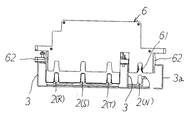
図20に示すプラグイン分電盤は、本発明の第2の実施形態を示すものであり、第1の実施形態と同様の部分は同じ符号を付して説明を省略する。
この実施形態では、遮断機能を有した3極用ブレーカ80と、遮断機能を有しないN相モジュール90とが一組で4極の主幹ブレーカとしての機能しており、分岐配線が接続される3極用ブレーカ5及びN相モジュール6と同列の母線バー2の最上部に配置されている。
The plug-in distribution board shown in FIG. 20 shows the second embodiment of the present invention, and the same parts as those of the first embodiment are denoted by the same reference numerals and the description thereof is omitted.
In this embodiment, the 3-
そして、最上部の3極用ブレーカ80の負荷側端子80aがプラグインアダプタ50を介して分電盤の母線バー2に接続されると共に、電源側端子80bに分電盤外部からの引込配線が接続されている。すなわち、3極用ブレーカ80は分岐配線を行う3極用ブレーカ5とは逆向きにプラグインアダプタ50に取り付けられたものである。また、N相モジュール90は分岐配線が接続されるN相モジュール6と全く同一のものであるが、その端子部90bは分電盤外部からの引込配線と接続されている。
The
このようなプラグイン分電盤にあっては、主幹ブレーカとして4極用ブレーカを設けずとも、遮断機能を有した3極用ブレーカ80と遮断機能を有しないN相モジュール90との組み合せにより4極の主幹ブレーカとして機能するものであり、さらに、プラグイン分電盤の製造コストを安価にできる利点を有する。
In such a plug-in distribution board, a 4-
なお、上記のいずれの実施形態においても、他の分電盤に三相4線式の配線を行うだけでなく、従来と同様に3極用ブレーカにより三相3線式の電源を負荷供給できると共に、2極用ブレーカとN相モジュールを一組として単相3線式の電源を負荷供給することができるプラグイン分電盤として使用できることは勿論である。 In any of the above-described embodiments, not only the three-phase four-wire wiring is performed on other distribution boards, but also a three-phase three-wire power supply can be supplied by a three-pole breaker as in the conventional case. In addition, as a matter of course, the two-pole breaker and the N-phase module can be used as a plug-in distribution board capable of supplying a single-phase three-wire power supply as a set.
2 母線バー
3 内部レール
3a 内部レール
5 3極用ブレーカ
51 プラグ端子金具
6 N相モジュール
61 プラグ端子金具
7 ハンドル
2 Busbar 3 Inner rail
3a
51 Plug terminal bracket 6 N-phase module
61
Claims (4)
The elastic piece which hold | maintains the plug terminal metal fitting of this N phase module in the state from which the connection from the N pole bus bar was cancelled | released in the N phase module fixed to the internal rail of a plug-in distribution board is provided. 2. Plug-in distribution board according to 2.
Priority Applications (1)
| Application Number | Priority Date | Filing Date | Title |
|---|---|---|---|
| JP2006115480A JP2007288963A (en) | 2006-04-19 | 2006-04-19 | Plug-in power distribution board |
Applications Claiming Priority (1)
| Application Number | Priority Date | Filing Date | Title |
|---|---|---|---|
| JP2006115480A JP2007288963A (en) | 2006-04-19 | 2006-04-19 | Plug-in power distribution board |
Publications (1)
| Publication Number | Publication Date |
|---|---|
| JP2007288963A true JP2007288963A (en) | 2007-11-01 |
Family
ID=38760225
Family Applications (1)
| Application Number | Title | Priority Date | Filing Date |
|---|---|---|---|
| JP2006115480A Withdrawn JP2007288963A (en) | 2006-04-19 | 2006-04-19 | Plug-in power distribution board |
Country Status (1)
| Country | Link |
|---|---|
| JP (1) | JP2007288963A (en) |
Cited By (3)
| Publication number | Priority date | Publication date | Assignee | Title |
|---|---|---|---|---|
| JP2007300707A (en) * | 2006-04-28 | 2007-11-15 | Nitto Electric Works Ltd | Self-standing distribution panel |
| JP2015208070A (en) * | 2014-04-18 | 2015-11-19 | 日東工業株式会社 | distribution board |
| JP2017038465A (en) * | 2015-08-07 | 2017-02-16 | パナソニックIpマネジメント株式会社 | Cabinet of distribution board, distribution board and construction method for distribution board |
-
2006
- 2006-04-19 JP JP2006115480A patent/JP2007288963A/en not_active Withdrawn
Cited By (3)
| Publication number | Priority date | Publication date | Assignee | Title |
|---|---|---|---|---|
| JP2007300707A (en) * | 2006-04-28 | 2007-11-15 | Nitto Electric Works Ltd | Self-standing distribution panel |
| JP2015208070A (en) * | 2014-04-18 | 2015-11-19 | 日東工業株式会社 | distribution board |
| JP2017038465A (en) * | 2015-08-07 | 2017-02-16 | パナソニックIpマネジメント株式会社 | Cabinet of distribution board, distribution board and construction method for distribution board |
Similar Documents
| Publication | Publication Date | Title |
|---|---|---|
| KR100964068B1 (en) | Electromagnetic protection and control assembly | |
| KR20060087344A (en) | A modular terminal in a mould cased circuit breaker | |
| EP2400610B1 (en) | Supporting bars and an electrical distribution module comprising said bars. | |
| JP3113266U (en) | Unit distribution board | |
| JP2007288963A (en) | Plug-in power distribution board | |
| JP5339527B2 (en) | Breaker unit | |
| JP2000188805A (en) | Connection conductor device of distribution board | |
| JP2008061455A (en) | Plug-in mounting adapter of quadripole breaker | |
| JP4722677B2 (en) | switchboard | |
| CN109564841B (en) | Voltage tap system for fuse box substrate, fuse box substrate and measurement module incorporating the system | |
| JP2004031354A (en) | Protection / control system for electric equipment, and shared electric power terminal board | |
| JP4501544B2 (en) | Distribution board | |
| JP7229803B2 (en) | changeover switch | |
| JP2008271710A (en) | Breaker unit | |
| JP4203552B2 (en) | Distribution board | |
| JP6433336B2 (en) | Distribution board | |
| DK2889893T3 (en) | Modular electrical appliance | |
| JP2007037246A (en) | Switchboard | |
| NO319544B1 (en) | Modular electrical appliance plugged into an insulated distribution block | |
| WO2023100303A1 (en) | Circuit breaker | |
| CA2997880A1 (en) | Modular ground fault protective relay and protection module therefor | |
| EP1189321A1 (en) | Wiring circuit breaker and switchboard | |
| US11538649B2 (en) | Circuit breaker housing | |
| JP2020182350A (en) | Distribution board | |
| KR100931842B1 (en) | switchboard |
Legal Events
| Date | Code | Title | Description |
|---|---|---|---|
| A300 | Withdrawal of application because of no request for examination |
Free format text: JAPANESE INTERMEDIATE CODE: A300 Effective date: 20090707 |