JP2007288564A - Operation panel, and image forming unit - Google Patents
Operation panel, and image forming unit Download PDFInfo
- Publication number
- JP2007288564A JP2007288564A JP2006114210A JP2006114210A JP2007288564A JP 2007288564 A JP2007288564 A JP 2007288564A JP 2006114210 A JP2006114210 A JP 2006114210A JP 2006114210 A JP2006114210 A JP 2006114210A JP 2007288564 A JP2007288564 A JP 2007288564A
- Authority
- JP
- Japan
- Prior art keywords
- operation panel
- pressing member
- base
- detection switch
- key
- Prior art date
- Legal status (The legal status is an assumption and is not a legal conclusion. Google has not performed a legal analysis and makes no representation as to the accuracy of the status listed.)
- Pending
Links
- 238000001514 detection method Methods 0.000 claims abstract description 32
- 238000003780 insertion Methods 0.000 claims description 12
- 230000037431 insertion Effects 0.000 claims description 12
- 230000000149 penetrating effect Effects 0.000 abstract 2
- 230000005540 biological transmission Effects 0.000 description 5
- 239000011521 glass Substances 0.000 description 2
- 238000010586 diagram Methods 0.000 description 1
- 230000000694 effects Effects 0.000 description 1
- 238000009434 installation Methods 0.000 description 1
- 239000004973 liquid crystal related substance Substances 0.000 description 1
- 239000000463 material Substances 0.000 description 1
- 238000000034 method Methods 0.000 description 1
- 238000012986 modification Methods 0.000 description 1
- 230000004048 modification Effects 0.000 description 1
Images

Landscapes
- Accessory Devices And Overall Control Thereof (AREA)
- Electrophotography Configuration And Component (AREA)
- Control Or Security For Electrophotography (AREA)
- Input From Keyboards Or The Like (AREA)
- Facsimiles In General (AREA)
Abstract
Description
本発明は、操作キーを配列する操作キー配列部に切換プレート等の開閉体を取り付けた操作パネル、及び該操作パネルを備えた画像形成装置に関するものである。 The present invention relates to an operation panel in which an opening / closing body such as a switching plate is attached to an operation key arrangement portion for arranging operation keys, and an image forming apparatus including the operation panel.
従来、複写機やファクシミリ装置やプリンタなどの画像形成装置には、特許文献1に示すように操作パネルが設けられている。この操作パネルでは、操作パネルカバーの上面側に操作キーを配列する操作キー配列部を設け、そこにワンタッチキーなどの特定の機能を備えた操作キーや使用頻度の少ない操作キーを配列している。そしてこの操作キー配列部に、複数枚の切換プレートを開閉自在に取り付け、この切換プレートの開閉状態に応じて各操作キーが有する複数の機能を切り換えることができるように構成している。
上記の操作パネルでは、操作パネルカバーの内部に切換プレートの開閉状態を検知する検知スイッチを設置している。そして検知スイッチと切換プレートの間に押圧部材を介在させている。この押圧部材は、検知スイッチを押圧する基部と、該基部の上面から突出し操作パネルカバーに設けた挿通部に挿通されてその先端が操作キー配列部の切換プレートに接触する突出部とを備えた形状に形成されている。 In the operation panel described above, a detection switch for detecting the open / closed state of the switching plate is installed inside the operation panel cover. A pressing member is interposed between the detection switch and the switching plate. The pressing member includes a base portion that presses the detection switch, and a protruding portion that protrudes from the upper surface of the base portion and is inserted into an insertion portion provided on the operation panel cover and has a tip that contacts the switching plate of the operation key array portion. It is formed into a shape.
ところが従来の押圧部材は、それ自体が非常に小さな部品である上に、基部の形状が平板形状であったために、手や工具でつまんで持つのが困難な部品であった。そのため操作パネルの組み立ての際に持ちにくく、その取付作業に手間がかかるという問題があった。特に、操作パネルカバーの下面側に筒状のガイドリブを形成している場合、上下面を反転させた操作パネルカバーのガイドリブ内にこの押圧部材を落とし込んで設置するが、押圧部材が持ちにくいために、ガイドリブ内で上下逆向きに設置されてしまうことが頻繁に起こっていた。すると一度設置した押圧部材を正しい状態に直す作業が必要になり、操作パネルの組み立て作業の効率が悪かった。また、一度正しい状態に設置してもガイドリブ内で反転して誤った状態で設置されてしまうため、操作パネルの組立不良につながるおそれがあった。 However, the conventional pressing member itself is a very small component, and the base portion has a flat plate shape, which makes it difficult to pinch with a hand or a tool. For this reason, it is difficult to hold the operation panel when assembling, and there is a problem that it takes time to install the operation panel. In particular, when a cylindrical guide rib is formed on the lower surface side of the operation panel cover, the pressing member is dropped and installed in the guide rib of the operation panel cover whose upper and lower surfaces are inverted. In the guide rib, it was frequently installed upside down. Then, it was necessary to work to correct the pressing member once installed, and the operation panel assembly work was inefficient. In addition, even if it is once installed in the correct state, it is inverted in the guide rib and installed in the wrong state, which may lead to an assembly failure of the operation panel.
本発明は上述の点に鑑みてなされたものでありその目的は、押圧部材の形状をつまみ易い形状に改善することで持ち易くし、組み立て作業の効率を向上させると共に組立不良を防止し、且つ安定的な動作をすることができる操作パネル、及び該操作パネルを備えた画像形成装置を提供することにある。 The present invention has been made in view of the above points, and its purpose is to make it easier to hold by improving the shape of the pressing member to a shape that is easy to pinch, improve the efficiency of assembly work, prevent assembly failure, and An object of the present invention is to provide an operation panel capable of stable operation and an image forming apparatus including the operation panel.
上記課題を解決するため本願の請求項1に記載の発明は、操作キーを配列する操作キー配列部を上面側に有する操作パネルカバーと、前記操作キー配列部に開閉自在に取り付けられた開閉体と、前記操作パネルカバーの内部に設置され前記開閉体の開閉状態を検知する検知スイッチと、前記開閉体と前記検知スイッチの間に介在する押圧部材とを備えた操作パネルにおいて、前記押圧部材は、前記検知スイッチのスイッチキーを押圧する基部と該基部の上面から突出し前記操作パネルカバーに設けた挿通部に挿通されて前記開閉体に接触する突出部とを有する形状であり、且つ前記押圧部材の基部を、その下面側に開口する凹部を備えた有底筒形状に形成したことを特徴とする。 In order to solve the above-mentioned problems, an invention according to claim 1 of the present application is directed to an operation panel cover having an operation key arrangement portion on the upper surface side for arranging operation keys, and an opening / closing body attached to the operation key arrangement portion so as to be freely opened and closed. And an operation panel provided with a detection switch that is installed inside the operation panel cover and detects an open / closed state of the opening / closing body, and a pressing member interposed between the opening / closing body and the detection switch. The pressing member is configured to have a base that presses a switch key of the detection switch, and a protruding portion that protrudes from the upper surface of the base and is inserted into an insertion portion provided in the operation panel cover and contacts the opening / closing body. The base portion is formed in a bottomed cylindrical shape having a recess opening on the lower surface side thereof.
本願の請求項2に記載の発明は、請求項1に記載の操作パネルにおいて、前記検知スイッチのスイッチキーが、前記押圧部材の凹部内に挿入配置されていることを特徴とする。 According to a second aspect of the present invention, in the operation panel according to the first aspect, the switch key of the detection switch is inserted and disposed in the recess of the pressing member.
本願の請求項3に記載の発明は、請求項1又は2に記載の操作パネルにおいて、前記押圧部材の基部が、前記操作パネルカバーの下面に形成された筒状のガイドリブ内に収納配置されていることを特徴とする。 According to a third aspect of the present invention, in the operation panel according to the first or second aspect, the base of the pressing member is housed and disposed in a cylindrical guide rib formed on the lower surface of the operation panel cover. It is characterized by being.
本願の請求項4に記載の発明は、請求項1乃至3のいずれか1項に記載の操作パネルにおいて、前記開閉体は、その開閉状態に応じて前記操作キー配列部に配列されている操作キーの機能を切り換える切換プレートであることを特徴とする。 According to a fourth aspect of the present invention, in the operation panel according to any one of the first to third aspects, the opening / closing body is an operation arranged in the operation key arrangement portion according to an open / closed state thereof. It is a switching plate for switching the function of the key.
本願の請求項5に記載の発明は、操作キーが配列された操作パネルを備えた画像形成装置において、前記操作パネルに、請求項1乃至4のいずれか1項に記載の操作パネルを用いたことを特徴とする。 According to a fifth aspect of the present invention, in the image forming apparatus including the operation panel on which the operation keys are arranged, the operation panel according to any one of the first to fourth aspects is used as the operation panel. It is characterized by that.
本願の請求項1に記載の発明によれば、押圧部材の基部が、その下面側に開口する凹部を備えた有底筒形状に形成されているので、この基部を手や工具でつまんで押圧部材を持つことができるので、押圧部材が非常に持ち易くなる。これにより押圧部材を設置する作業が容易になり、操作パネルの組み立て作業の効率を向上させることができる。 According to the invention described in claim 1 of the present application, the base portion of the pressing member is formed in a bottomed cylindrical shape having a concave portion opened on the lower surface side thereof, so that the base portion is pinched with a hand or a tool and pressed. Since it can have a member, it becomes very easy to hold a pressing member. As a result, the operation of installing the pressing member is facilitated, and the efficiency of the operation panel assembly operation can be improved.
本願の請求項2に記載の発明によれば、操作パネルの構造上、操作パネルカバーとスイッチキーとの隙間寸法が限られている場合でも、押圧部材の凹部内にスイッチキーを挿入配置したことで、有底筒形状に形成した押圧部材の基部の適切な高さ寸法を確保できるので、押圧部材の持ち易さを改善することが可能となる。 According to the invention described in claim 2 of the present application, even when the gap between the operation panel cover and the switch key is limited due to the structure of the operation panel, the switch key is inserted and disposed in the recess of the pressing member. Thus, since it is possible to ensure an appropriate height dimension of the base portion of the pressing member formed in the bottomed cylindrical shape, it becomes possible to improve the ease of holding the pressing member.
本願の請求項3に記載の発明によれば、操作パネルを組み立てる際に、押圧部材を筒状のガイドリブ内に落とし込んで設置する工程が必要になるが、押圧部材はその基部を有底筒形状に形成していることで持ち易さを改善しているので、上下が反転した状態でガイドリブ内に設置されることを防止でき、操作パネルの組み立て作業の効率を向上させることができる。また、基部を有底筒形状に形成していることで、設置した押圧部材がガイドリブ内で反転することも防げるので、組立不良を防止できる。また、基部を有底筒形状に形成していることで、該基部が適度な高さ寸法を有するように構成できるので、ガイドリブ内に設置されている該基部が、例えばシリンダ内に設置されているピストンのようにスムーズな上下動作をすることができ、押圧部材の安定的な動作が実現できる。 According to the invention described in claim 3 of the present application, when assembling the operation panel, a step of dropping the pressing member into the cylindrical guide rib and installing it is necessary, and the pressing member has a bottomed cylindrical shape. Since the ease of holding is improved by being formed, it can be prevented from being installed in the guide rib in a state where the top and bottom are inverted, and the efficiency of the assembly operation of the operation panel can be improved. Moreover, since the base is formed in a bottomed cylindrical shape, it is possible to prevent the installed pressing member from being reversed in the guide rib, and thus it is possible to prevent assembly failure. In addition, since the base is formed in a bottomed cylindrical shape, the base can be configured to have an appropriate height, so that the base installed in the guide rib is installed in a cylinder, for example. It can move up and down smoothly like a piston, and a stable operation of the pressing member can be realized.
本願の請求項4に記載の発明によれば、切換プレートの開閉状態を検知する検知スイッチを備えた操作パネルの組み立て作業の効率を向上させることができる。 According to the invention described in claim 4 of the present application, it is possible to improve the efficiency of the operation of assembling the operation panel provided with the detection switch for detecting the open / close state of the switching plate.
本願の請求項5に記載の発明によれば、押圧部材の形状を改善した操作パネルを備えることで、画像形成装置の組み立て作業の効率を向上させることができる。 According to the invention described in claim 5 of the present application, the efficiency of the assembling work of the image forming apparatus can be improved by providing the operation panel with the improved shape of the pressing member.
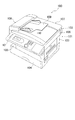
以下、本発明の実施形態を図面に基づいて詳細に説明する。図1は、本発明の一実施形態にかかる操作パネル10を備えた画像形成装置100の全体構成を示す斜視図で、図2は、操作パネル10の構成を示す斜視図である。まず図1を用いて画像形成装置100の概略全体構成について説明する。本発明にかかる画像形成装置としては、操作キーを配置した操作パネルを有する画像形成装置であれば、コピー機やファクシミリ装置やプリンタ或いはこれらの機能を兼ね備えたいわゆる複合機のうちのいずれであっても良い。同図に示す画像形成装置100は、下段側に配置した記録部101と上段側に配置した読取部102とを備えて構成されている。記録部101には、記録装置103と給紙カセット104及び記録紙排出トレイ105が内装され、給紙カセット104内に収容されている用紙を記録装置103へ給紙し、該記録装置103で用紙への記録を行った後、用紙を記録紙排出トレイ105へ排出するように構成されている。
Hereinafter, embodiments of the present invention will be described in detail with reference to the drawings. FIG. 1 is a perspective view showing the overall configuration of an
一方、読取部102は、読取ケース106内に読取装置(図示せず)を収納しており、読取ケース106の上面側に設置したプラテンガラス(図示せず)上に載置された原稿を読取装置で走査して読み取るようになっている。また、読取ケース106の上部には、その一辺を中心に開閉可能に取り付けられた原稿押えカバー107が配置され、該原稿押えカバー107でプラテンガラス上に載置された原稿を上方から押えるように構成している。さらに原稿押えカバー107の一端部には、原稿を自動的に給紙する自動給紙装置(ADF装置)108が付設されている。この自動給紙装置108は、原稿供給トレイ109に載置された原稿を一枚ずつピックアップして、搬送装置(図示せず)で読取ケース106上面の一端部に設けられたADF読取部(図示せず)へ搬送し、静止状態の読取装置で原稿を読み取った後、原稿押えカバー107の上面に設けた原稿排出トレイ110へ排出するように構成している。このように読取部102は、読取装置を走査させて静止原稿を読み取るフラットベッドタイプのスキャナとしても、読取装置の位置を固定して原稿を給送しながら読み取りを行うシートフィードタイプのスキャナとしても用いることができるように構成されている。
On the other hand, the
そして、読取ケース106の一方の側部(画像形成装置100の前面側の側部)に操作パネル10が設置されている。図2に示すように、操作パネル10には、略長方形で平板状の操作パネルカバー11が取り付けられ、該操作パネルカバー11の上面11aに設けた挿通部から各種操作キーが露出している。各種操作キーには、原稿内容のファクシミリ送信やコピーを開始するためのスタートキー21や、これらの動作を途中で停止するためのストップキー22や、ファクシミリ送信先へダイヤルしたりコピー枚数を設定したりするためのテンキー23や、画像形成装置100の各種設定や操作内容の選択・決定を行うカーソルキー24や、下記するワンタッチキー25などがある。これら各種操作キーを操作することで、読取装置で原稿内容の読み取りを行ったり、原稿をコピーする際のコピー枚数や用紙サイズを指定したり、受信内容を記録装置103で記録するなど、画像形成装置100における各種操作を行なうことができる。また、操作パネル10には表示部15が設けられている。表示部15は、操作パネルカバー11に設けた開口部13に露出する液晶表示器16を備え、画像形成装置100の動作状態や設定状態などの各種情報を表示する。
The
そして、操作パネルカバー11の上面11aの一方の側部には、ワンタッチキー25を配列するワンタッチキー配列部30が設けられている。ここに配列されているワンタッチキー25は、ファクシミリ送信の相手先を予め登録しておき、ワンタッチ操作で当該相手先へのファクシミリ送信を行える機能や、複数の操作手順を予め登録しておき、ワンタッチ操作で当該複数の操作を一括して行なえるようにする機能などを備えた操作キーである。
A one-touch
ワンタッチキー配列部30は、ワンタッチキー25が配列されている底部30aが、操作パネルカバー11の上面11aよりも若干低くなった凹部状に形成されると共に、上部に開閉カバー31が取り付けられている。また底部30aには、複数枚の切換プレート32(32−1,32−2,32−3)が重ねられた状態で取り付けられている。各切換プレート32は、ヒンジ部33を支点に回動自在に取り付けられており、下方に回動させて閉じたり、その閉じた状態から上方に回動させて開いたりできるようになっている。各切換プレート32には、ワンタッチキー25を挿通させる開口部32aが形成されていて、重ねられた各切換プレート32の開口部32aからワンタッチキー25の上部が突出している。ワンタッチキー25は、全部の切換プレート32を閉じた状態でも、最上段に重ねられた切換プレート32−1の上面から突出するようになっている。また各切換プレート32は、その表面に、それぞれのワンタッチキー25に登録されている送信先の名称等を記載したり当該名称等を記載したラベルを貼付したりできるようになっている。なお各図では3枚の切換プレート32(32−1,32−2,32−3)を設置した場合を示すが、切換プレート32の枚数はこれに限定されず、他の枚数としても良い。
The one-touch
またワンタッチキー配列部30の底部30aには、検知スイッチ40(40−1,40−2,40−3)が設置されている。この検知スイッチ40で各切換プレート32の開閉状態を検知することで、ワンタッチキー25の操作内容を、そのとき閉じている切換プレート32のうち最上段に重ねられている切換プレート32の表面に記された操作内容に切り換えることができるようになっている。
Further, the detection switch 40 (40-1, 40-2, 40-3) is installed on the bottom 30a of the one-touch
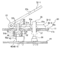
図3は、操作パネル10のワンタッチキー配列部30の概略側断面図である。同図を用いて検知スイッチ40(40−1)の詳細構成を説明する。操作パネルカバー11の内部に設置された回路基盤41上に、検知スイッチ40の本体部42が取り付けられ、この本体部42の上面から突起状のスイッチキー43が突出している。スイッチキー43は、図示しない付勢手段によって上方に向かって付勢されており、押圧されると下降して検知スイッチ40を作動するようになっている。一方、操作パネルカバー11の検知スイッチ40に対応する位置には、円形の開口からなる挿通部35が形成され、操作パネルカバー11の下面11bの挿通部35の周囲には円筒状のガイドリブ36が形成されている。そしてこのガイドリブ36内に押圧部材50が設置されている。
FIG. 3 is a schematic sectional side view of the one-touch
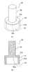
図4は押圧部材50を示す図で、同図(a)はその斜視図、同図(b)はその側断面図である。押圧部材50は、その下面側に開口する凹部52を備えた有底筒形状に形成された基部51と、該基部51の上面51aに立接された円柱状の突出部53とを備えている。突出部53の外径寸法は、基部51の筒状部分51bの外径寸法よりも小さい寸法になっている。この押圧部材50は、図3に示すように、基部51が操作パネルカバー11のガイドリブ36内に配置されて、突出部53が挿通部35に挿通されて操作パネルカバー11の上面11a側のワンタッチキー配列部30に突出した状態で設置されている。また基部51の凹部52内に、検知スイッチ40のスイッチキー43が挿入配置されて、該スイッチキー43の先端43aが凹部52の内底面52aに当接している。これによりスイッチキー43に加わっている付勢力で押圧部材50が上方に向かって付勢されており、基部51の上面51aが操作パネルカバー11の下面11bに当接した状態になっている。また押圧部材50は、基部51の外側面がガイドリブ36の内側面に摺接してその上下動がガイドされるように設置されている。
4A and 4B are views showing the pressing
図3に示す検知スイッチ40−1は、最上段の切換プレート32−1に対応して設けているもので、他の切換プレート32−2,32−3にはこの検知スイッチ40−1が備える押圧部材50の突出部53を挿通させる挿通部32bが形成されている。また、詳細な図示は省略するが、他の切換プレート32−2,32−3に対してもその開閉状態を検知する検知スイッチ40−2,40−3(図2参照)がそれぞれ設けられている。検知スイッチ40−2,40−3は、検知スイッチ40−1と同じ構成である。一方で、回路基盤41上には、スイッチ26上に設置されたワンタッチキー25のキートップ25aが配置されており、キートップ25aは、操作パネルカバー11の挿通部37に挿通されてその上部がワンタッチキー配列部30に突出している。
The detection switch 40-1 shown in FIG. 3 is provided corresponding to the uppermost switching plate 32-1, and the other switching plates 32-2 and 32-3 are provided with the detection switch 40-1. An
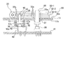
図5は、切換プレート32−1を閉じた状態を示す図である。同図に示すように切換プレート32−1を閉じて下段の切換プレート32−2の上に重ねると、押圧部材50の突出部53が切換プレート32−1の下面で押し下げられて、押圧部材50が下降する。これにより押圧部材50の基部51(詳細には、基部51の凹部52の内底面52a)でスイッチキー43が押し下げられて、検知スイッチ40が作動する。
FIG. 5 is a diagram illustrating a state in which the switching plate 32-1 is closed. As shown in the figure, when the switching plate 32-1 is closed and overlapped on the lower switching plate 32-2, the
この操作パネル10では、押圧部材50の基部51がその下面側に開口する凹部52を備えた有底筒形状に形成されているので、操作パネル10の組み立て作業において、この基部51を手やピンセットでつまんで持つことができ、押圧部材50が持ち易い。それにより操作パネル10の組み立て作業の効率が向上する。特に、上記構成の操作パネル10の組み立て作業では、操作パネルカバー11の上下面を反転させて、その下面11b側に形成されているガイドリブ36内に押圧部材50を落とし込んで設置する工程を有するが、従来の平板状の基部を備えた押圧部材では、基部をつまみにくかったので、先に述べたように押圧部材をガイドリブ36内に設置する際に上下逆向きに設置されてしまうことが頻繁に起こっていた。しかしながら本発明の操作パネル10が備える押圧部材50では、基部51の形状をつまんで持ち易い形状に改善したことで、基部51をつまんで押圧部材50を持ち、突出部53をガイドリブ36内に差し込むようにして押圧部材50の全体を落とし込めば、容易に正しい姿勢に設置することができるので、設置した後の押圧部材50の上下を反転させる作業が不要になり、操作パネル10の組み立て作業の効率を向上させることができる。また、押圧部材50の基部51が有底筒形状に形成されて、この基部51が適切な高さ寸法を有していることで、一度設置した押圧部材50がガイドリブ36内で反転することを防げるので、操作パネル10の組立不良を防止できる。
In the
また、上記実施形態の操作パネル10では、その構造上、操作パネルカバー11の内部の上下方向のスペースが限られているため、操作パネルカバー11と検知スイッチ40のスイッチキー43との隙間寸法(上下方向の隙間寸法)をあまり広くできないが、押圧部材50の凹部52内に検知スイッチ40のスイッチキー43を挿入配置したことで、検知スイッチ40や押圧部材50の動作を阻害することなく、有底筒形状に形成した押圧部材50の基部51の適切な高さ寸法を確保でき、押圧部材50の持ち易さを改善することが可能となる。
In addition, since the
以上本発明の実施形態を説明したが、本発明は上記実施形態に限定されるものではなく、特許請求の範囲、及び明細書、図面に記載された技術的思想の範囲内において種々の変形が可能である。なお、直接明細書及び図面に記載のない何れの形状・構造・材質であっても、本願発明の作用・効果を奏する以上、本願発明の技術的思想の範囲内である。例えば、ワンタッチキー25や切換プレート32(32−1,32−2,32−3)の具体的な形状や構造は、上記実施形態に示すものには限定されず他の形状や構造であってもよい。例えば切換プレート32は、上記実施形態のように、ワンタッチキー配列部30の奥側にヒンジ部33を形成し、切換プレート32がヒンジ部33の手前側で開閉する以外にも、ヒンジ部をワンタッチキー配列部30の中央部に形成し、切換プレートがこのヒンジ部の左右両側あるいは手前側と奥側に開閉するように構成してもよい。
Although the embodiments of the present invention have been described above, the present invention is not limited to the above-described embodiments, and various modifications can be made within the scope of the technical idea described in the claims, the specification, and the drawings. Is possible. It should be noted that any shape, structure, and material not directly described in the specification and drawings are within the scope of the technical idea of the present invention as long as the effects and advantages of the present invention are exhibited. For example, the specific shape and structure of the one-
また本発明にかかるワンタッチキー配列部30に配列する操作キーの種類は、ワンタッチキー25には限定されず、これ以外にも特定の機能を備えた他の操作キーを配列したり、使用頻度の少ない操作キーを集約して配列したりすることも可能である。また本発明にかかる開閉体は、上記実施形態で示した切換プレート32以外にも、開閉可能に設置されたものであれば他の部品でも良く、例えば開閉カバー31をこの開閉体として検知スイッチ40で開閉カバー31の開閉状態を検知するように構成しても良い。
The type of operation keys arranged in the one-touch
10 操作パネル
11 操作パネルカバー
11a 上面
11b 下面
15 表示部
21 スタートキー
22 ストップキー
23 テンキー
24 カーソルキー
25 ワンタッチキー
30 ワンタッチキー配列部(操作キー配列部)
30a 底部
31 開閉カバー
32 切換プレート(開閉体)
32a 開口部
32b 挿通部
33 ヒンジ部
35 挿通部
36 ガイドリブ
37 挿通部
40 検知スイッチ
41 回路基盤
42 本体部
43 スイッチキー
50 押圧部材
51 基部
51b 筒状部分
52 凹部
52a 内底面
53 突出部
100 画像形成装置
DESCRIPTION OF
Claims (5)
前記押圧部材は、前記検知スイッチのスイッチキーを押圧する基部と該基部の上面から突出し前記操作パネルカバーに設けた挿通部に挿通されて前記開閉体に接触する突出部とを有する形状であり、且つ前記押圧部材の基部を、その下面側に開口する凹部を備えた有底筒形状に形成したことを特徴とする操作パネル。 An operation panel cover having an operation key arrangement portion on the upper surface side for arranging operation keys, an opening / closing body attached to the operation key arrangement portion so as to be freely opened and closed, and an open / closed state of the opening / closing body installed inside the operation panel cover In an operation panel provided with a detection switch for detecting, and a pressing member interposed between the opening and closing body and the detection switch,
The pressing member has a shape that includes a base that presses a switch key of the detection switch, and a protruding portion that protrudes from an upper surface of the base and is inserted into an insertion portion provided in the operation panel cover and contacts the opening / closing body. In addition, the operation panel is characterized in that the base of the pressing member is formed in a bottomed cylindrical shape having a recess opening on the lower surface side thereof.
前記検知スイッチのスイッチキーが、前記押圧部材の凹部内に挿入配置されていることを特徴とする操作パネル。 The operation panel according to claim 1,
An operation panel, wherein a switch key of the detection switch is inserted and disposed in a recess of the pressing member.
前記押圧部材の基部が、前記操作パネルカバーの下面に形成された筒状のガイドリブ内に収納配置されていることを特徴とする操作パネル。 In the operation panel according to claim 1 or 2,
An operation panel in which a base portion of the pressing member is housed and disposed in a cylindrical guide rib formed on a lower surface of the operation panel cover.
前記開閉体は、その開閉状態に応じて前記操作キー配列部に配列されている操作キーの機能を切り換える切換プレートであることを特徴とする操作パネル。 The operation panel according to any one of claims 1 to 3,
The operation panel, wherein the opening / closing body is a switching plate for switching a function of an operation key arranged in the operation key arrangement unit according to an opened / closed state thereof.
前記操作パネルに、請求項1乃至4のいずれか1項に記載の操作パネルを用いたことを特徴とする画像形成装置。 In an image forming apparatus including an operation panel in which operation keys are arranged,
An image forming apparatus using the operation panel according to claim 1 as the operation panel.
Priority Applications (1)
| Application Number | Priority Date | Filing Date | Title |
|---|---|---|---|
| JP2006114210A JP2007288564A (en) | 2006-04-18 | 2006-04-18 | Operation panel, and image forming unit |
Applications Claiming Priority (1)
| Application Number | Priority Date | Filing Date | Title |
|---|---|---|---|
| JP2006114210A JP2007288564A (en) | 2006-04-18 | 2006-04-18 | Operation panel, and image forming unit |
Publications (1)
| Publication Number | Publication Date |
|---|---|
| JP2007288564A true JP2007288564A (en) | 2007-11-01 |
Family
ID=38759907
Family Applications (1)
| Application Number | Title | Priority Date | Filing Date |
|---|---|---|---|
| JP2006114210A Pending JP2007288564A (en) | 2006-04-18 | 2006-04-18 | Operation panel, and image forming unit |
Country Status (1)
| Country | Link |
|---|---|
| JP (1) | JP2007288564A (en) |
Cited By (2)
| Publication number | Priority date | Publication date | Assignee | Title |
|---|---|---|---|---|
| KR20180001310A (en) * | 2016-06-27 | 2018-01-04 | 주식회사 엘지씨엔에스 | Information leakage prevention apparatus and information inputting apparatus |
| JPWO2022163566A1 (en) * | 2021-01-26 | 2022-08-04 |
-
2006
- 2006-04-18 JP JP2006114210A patent/JP2007288564A/en active Pending
Cited By (3)
| Publication number | Priority date | Publication date | Assignee | Title |
|---|---|---|---|---|
| KR20180001310A (en) * | 2016-06-27 | 2018-01-04 | 주식회사 엘지씨엔에스 | Information leakage prevention apparatus and information inputting apparatus |
| JPWO2022163566A1 (en) * | 2021-01-26 | 2022-08-04 | ||
| JP7742028B2 (en) | 2021-01-26 | 2025-09-19 | 日本精機株式会社 | Control device, control panel |
Similar Documents
| Publication | Publication Date | Title |
|---|---|---|
| JP2007288564A (en) | Operation panel, and image forming unit | |
| JP2006270618A (en) | Original reading device | |
| JP2004119238A (en) | Tact switch | |
| JP3721975B2 (en) | Key panel | |
| JP2019202866A (en) | Image forming apparatus | |
| JP2006184701A (en) | Image scanner | |
| JP3485058B2 (en) | control panel | |
| US9204002B2 (en) | Electronic device with keys, control method thereof, and storage medium | |
| JP2007281955A (en) | Operation panel and image forming apparatus | |
| JP3685034B2 (en) | Key panel | |
| JP2016054370A (en) | Reading device | |
| JP2008077508A (en) | Operation panel and image forming device | |
| JP2019130796A (en) | Image forming apparatus | |
| JP5942806B2 (en) | Image reading device | |
| JP4941667B2 (en) | Image reading device | |
| JP4715674B2 (en) | Image reading device | |
| JP3919762B2 (en) | Image reading device | |
| JP2000284559A (en) | Image forming device | |
| JPH09244161A (en) | Image reading device | |
| JP2019176250A (en) | Image reading device | |
| JP4013451B2 (en) | control panel | |
| JP4251165B2 (en) | Image forming apparatus | |
| JP4140172B2 (en) | Opening / closing state detection mechanism of opening / closing body | |
| JP2025152059A (en) | Image reading device | |
| JP2006201561A (en) | Movable cover and composite printer with the same |
Legal Events
| Date | Code | Title | Description |
|---|---|---|---|
| A977 | Report on retrieval |
Free format text: JAPANESE INTERMEDIATE CODE: A971007 Effective date: 20081211 |
|
| A131 | Notification of reasons for refusal |
Free format text: JAPANESE INTERMEDIATE CODE: A131 Effective date: 20081216 |
|
| A02 | Decision of refusal |
Free format text: JAPANESE INTERMEDIATE CODE: A02 Effective date: 20090407 |