JP2007283099A - Table system specifying method and medical imaging apparatus - Google Patents
Table system specifying method and medical imaging apparatus Download PDFInfo
- Publication number
- JP2007283099A JP2007283099A JP2007100376A JP2007100376A JP2007283099A JP 2007283099 A JP2007283099 A JP 2007283099A JP 2007100376 A JP2007100376 A JP 2007100376A JP 2007100376 A JP2007100376 A JP 2007100376A JP 2007283099 A JP2007283099 A JP 2007283099A
- Authority
- JP
- Japan
- Prior art keywords
- table system
- movable part
- medical imaging
- imaging apparatus
- axis
- Prior art date
- Legal status (The legal status is an assumption and is not a legal conclusion. Google has not performed a legal analysis and makes no representation as to the accuracy of the status listed.)
- Granted
Links
- 238000000034 method Methods 0.000 title claims abstract description 36
- 238000002059 diagnostic imaging Methods 0.000 title claims abstract description 20
- 238000012512 characterization method Methods 0.000 claims abstract description 19
- 230000003287 optical effect Effects 0.000 claims description 45
- 238000001514 detection method Methods 0.000 claims description 44
- 238000013480 data collection Methods 0.000 claims description 18
- 230000005855 radiation Effects 0.000 claims description 11
- 230000000903 blocking effect Effects 0.000 claims description 7
- 239000008177 pharmaceutical agent Substances 0.000 claims 1
- 238000002591 computed tomography Methods 0.000 description 11
- 238000002600 positron emission tomography Methods 0.000 description 11
- 238000012790 confirmation Methods 0.000 description 3
- 238000005070 sampling Methods 0.000 description 3
- 239000003814 drug Substances 0.000 description 2
- 238000005259 measurement Methods 0.000 description 2
- 229940079593 drug Drugs 0.000 description 1
- 238000005457 optimization Methods 0.000 description 1
- 238000012545 processing Methods 0.000 description 1
- 230000004044 response Effects 0.000 description 1
- 230000000630 rising effect Effects 0.000 description 1
- 210000003371 toe Anatomy 0.000 description 1
Images


Classifications
-
- A—HUMAN NECESSITIES
- A61—MEDICAL OR VETERINARY SCIENCE; HYGIENE
- A61B—DIAGNOSIS; SURGERY; IDENTIFICATION
- A61B6/00—Apparatus for radiation diagnosis, e.g. combined with radiation therapy equipment
- A61B6/02—Devices for diagnosis sequentially in different planes; Stereoscopic radiation diagnosis
- A61B6/03—Computerised tomographs
- A61B6/032—Transmission computed tomography [CT]
-
- A—HUMAN NECESSITIES
- A61—MEDICAL OR VETERINARY SCIENCE; HYGIENE
- A61B—DIAGNOSIS; SURGERY; IDENTIFICATION
- A61B6/00—Apparatus for radiation diagnosis, e.g. combined with radiation therapy equipment
- A61B6/04—Positioning of patients; Tiltable beds or the like
- A61B6/0487—Motor-assisted positioning
-
- A—HUMAN NECESSITIES
- A61—MEDICAL OR VETERINARY SCIENCE; HYGIENE
- A61B—DIAGNOSIS; SURGERY; IDENTIFICATION
- A61B6/00—Apparatus for radiation diagnosis, e.g. combined with radiation therapy equipment
- A61B6/40—Apparatus for radiation diagnosis, e.g. combined with radiation therapy equipment with arrangements for generating radiation specially adapted for radiation diagnosis
- A61B6/4064—Apparatus for radiation diagnosis, e.g. combined with radiation therapy equipment with arrangements for generating radiation specially adapted for radiation diagnosis specially adapted for producing a particular type of beam
- A61B6/4085—Cone-beams
-
- A—HUMAN NECESSITIES
- A61—MEDICAL OR VETERINARY SCIENCE; HYGIENE
- A61B—DIAGNOSIS; SURGERY; IDENTIFICATION
- A61B6/00—Apparatus for radiation diagnosis, e.g. combined with radiation therapy equipment
- A61B6/54—Control of apparatus or devices for radiation diagnosis
- A61B6/547—Control of apparatus or devices for radiation diagnosis involving tracking of position of the device or parts of the device
Abstract
Description
本発明は、テーブルシステム(table system)特定方法および医療用イメージング(imaging)装置に関し、さらに詳しくは、それぞれの軸方向において独立に移動可能な複数の可動部を有するテーブルシステムの特定方法、および、そのようなテーブルシステムを有する医療用イメージング装置に関する。 The present invention relates to a table system identification method and a medical imaging apparatus, and more specifically, a table system identification method having a plurality of movable parts that can move independently in the respective axial directions, and The present invention relates to a medical imaging apparatus having such a table system.
PET(Positron Emission Tomography)装置とX線CT(Computed Tomography)装置とを複合化したPET−CT装置では、独立に移動可能な複数の可動部を有するテーブルシステムが用いられる(例えば、特許文献1参照)。 In a PET-CT apparatus in which a PET (Positron Emission Tomography) apparatus and an X-ray CT (Computed Tomography) apparatus are combined, a table system having a plurality of independently movable parts is used (for example, see Patent Document 1). ).
複数の可動部としては、例えば、被検体を支持して水平方向に移動するクレードル(cradle)、クレードルを支持して水平方向に移動するインターメディエイト・サポート(intermediate support: IMS)、IMSを支持して垂直方向に移動するエレベーション(elevation)、エレベーションを支持して水平方向に移動するトランスポータ(transporter)等がある。 As the plurality of movable parts, for example, a cradle that supports a subject and moves in a horizontal direction, an intermediate support (IMS) that supports a cradle and moves in a horizontal direction, and an IMS are supported. Thus, there are an elevation that moves in the vertical direction, a transporter that supports the elevation and moves in the horizontal direction, and the like.
テーブルシステムについては、稼働前にシステムの特定が行われる。システムの特定は、システムについてのキャラクタライゼーション(characterization)とコンフィギュレーション(configuration)確認とによって行われる。 For the table system, the system is specified before operation. The system is identified by characterization and configuration confirmation of the system.
キャラクタライゼーションは、各軸の可動部について距離計測系の測定値を校正することによって行われる。測定値の校正は、移動軸に沿って所定の2箇所に設けられた穴に手作業でそれぞれピン(pin)を差し込み、それらピンによって可動部の移動が阻止されたときのエンコーダ(encoder)出力をそれぞれ読み取り、それら読取値と予めわかっているピン穴間距離とを用いて行われる。 The characterization is performed by calibrating the measurement value of the distance measurement system for the movable part of each axis. Calibration of measured values is performed by manually inserting pins into holes provided at two predetermined locations along the movement axis, and the encoder output when the movement of the moving part is blocked by these pins. Are read out using the read values and the distance between pin holes known in advance.
コンフィギュレーション確認は、インターフェースボード(interface board)に差し込まれたコンフィギュレーションピンの種類を電気的に読み取ることによって行われる。コンフィギュレーションピンは、コンフィギュレーションの種類ごとに用意され、該当のものがインターフェースボードに差し込まれる。
上記のような方法によるテーブルシステム特定は、手作業を要するので時間と労力がかかり、しかも、システム特定の信頼性は作業者のスキル(skill)によって左右される。
そこで、本発明の課題は、テーブルシステムの特定を自動的に行う方法および医療用イメージング装置を実現することである。
Specifying a table system by the above method requires time and labor because it requires manual work, and the reliability of the system specification depends on the skill of the operator.
Therefore, an object of the present invention is to realize a method and a medical imaging apparatus for automatically specifying a table system.
上記各観点での発明によれば、前記軸のおのおのについて、軸上の前記可動部の絶対位置を検出し、軸に沿って予め定められた距離を隔てて設定された2つの位置における前記可動部の通過をそれぞれ光学的に検知してそのときの可動部の各絶対位置をキャラクタライゼーション情報として記憶し、軸の両端における2つの阻止位置への前記可動部の到達をそれぞれ検知してそのときの可動部の各絶対位置をコンフィギュレーション情報として記憶するので、テーブルシステムの特定を自動的に行うことができる。 According to the invention in each aspect described above, for each of the shafts, the absolute position of the movable portion on the shaft is detected, and the movable at two positions set at a predetermined distance along the shaft. Optically detecting the passage of each part, storing each absolute position of the movable part as characterization information, and detecting the arrival of the movable part at the two blocking positions at both ends of the shaft. Since each absolute position of the movable part is stored as configuration information, the table system can be specified automatically.
上記の課題を解決するための第1の観点での本発明は、それぞれの軸方向において独立に移動可能な複数の可動部を有するテーブルシステムを特定するに当たり、前記軸のおのおのについて、軸上の前記可動部の絶対位置を検出し、軸に沿って予め定められた距離を隔てて設定された2つの位置における前記可動部の通過をそれぞれ光学的に検知してそのときの可動部の各絶対位置をキャラクタライゼーション情報として記憶し、軸の両端における2つの阻止位置への前記可動部の到達をそれぞれ検知してそのときの可動部の各絶対位置をコンフィギュレーション情報として記憶する、ことを特徴とするテーブルシステム特定方法である。 According to the first aspect of the present invention for solving the above-described problem, in specifying a table system having a plurality of movable parts that can move independently in the respective axial directions, The absolute position of the movable part is detected, the passage of the movable part at two positions set at a predetermined distance along the axis is optically detected, and each absolute value of the movable part at that time is detected. Storing the position as characterization information, detecting the arrival of the movable part at two blocking positions at both ends of the shaft, and storing each absolute position of the movable part at that time as configuration information, This is a table system specifying method.
上記の課題を解決するための第2の観点での本発明は、被検体に投与された医薬品が発生する放射線による投影データを収集する第1のデータ収集装置と、被検体をX線でスキャンして投影データを収集する第2のデータ収集装置と、前記第1のデータ収集装置および前記第2のデータ収集装置によってそれぞれ収集された投影データに基づいてそれぞれ画像を再構成する画像再構成装置と、それぞれの軸方向において独立に移動可能な複数の可動部を有し、被検体を前記第1のデータ収集装置のデータ収集位置または前記第2のデータ収集装置のデータ収集位置に選択的に搬送するテーブルシステムと、前記テーブルシステムを特定するテーブルシステム特定装置と、を有する医療用イメージング装置であって、前記テーブルシステム特定装置は、前記テーブルシステムの各軸について、軸上の前記可動部の絶対位置を検出する絶対位置検出手段と、前記テーブルシステムの各軸について、軸に沿って予め定められた距離を隔てて設定された2つの位置における前記可動部の通過をそれぞれ光学的に検知する第1の検知手段と、前記第1の検知手段が前記可動部の通過を検知したときの可動部の各絶対位置をキャラクタライゼーション情報として記憶する第1の記憶手段と、前記テーブルシステムの各軸について、軸の両端における2つの阻止位置への前記可動部の到達をそれぞれ検知する第2の検知手段と、前記第2の検知手段が前記可動部の到達を検知したときの可動部の各絶対位置をコンフィギュレーション情報として記憶する第2の記憶手段と、を有する、ことを特徴とする医療用イメージング装置である。 According to a second aspect of the present invention for solving the above-described problem, the present invention provides a first data collection device that collects projection data by radiation generated by a medicine administered to a subject, and scans the subject with X-rays. And a second data collection device for collecting projection data, and an image reconstruction device for reconstructing images based on the projection data collected by the first data collection device and the second data collection device, respectively. And a plurality of movable parts that can move independently in the respective axial directions, and the subject is selectively placed at the data collection position of the first data collection device or the data collection position of the second data collection device. A medical imaging apparatus having a table system to be transported and a table system specifying device for specifying the table system, the table system specifying For each axis of the table system, the absolute position detecting means for detecting the absolute position of the movable part on the axis and a predetermined distance along the axis for each axis of the table system are set. A first detection means for optically detecting the passage of the movable part at each of the two positions, and the absolute position of the movable part when the first detection means detects the passage of the movable part. First storage means for storing the information as the optimization information; second detection means for detecting the arrival of the movable part at two blocking positions at both ends of the shaft for each axis of the table system; and the second Second storage means for storing, as configuration information, each absolute position of the movable part when the detection means detects the arrival of the movable part, That is a medical imaging apparatus.
前記2つの位置における前記可動部の通過をそれぞれの位置に設けられた光学的センサで検知することが、非接触で検知する点で好ましい。
前記光学的センサは受光タイプのセンサであることが、受光方式で検知する点で好ましい。
It is preferable that the passage of the movable part at the two positions is detected by optical sensors provided at the respective positions in that they are detected without contact.
The optical sensor is preferably a light receiving type sensor in terms of detection by a light receiving method.
前記光学的センサは遮光タイプのセンサであることが、遮光方式で検知する点で好ましい。
前記キャラクタライゼーション情報および前記コンフィギュレーション情報を全軸について記憶した後にフラグを設定することが、テーブルシステム特定の有無を明確にする点で好ましい。
The optical sensor is preferably a light-shielding type sensor in terms of detection by a light-shielding method.
It is preferable to set a flag after storing the characterization information and the configuration information for all axes in order to clarify whether or not the table system is specified.
前記フラグの有無に基づいてテーブルシステム特定の要否を判定することが、テーブルシステム特定の重複を回避する点で好ましい。
前記コンフィギュレーション情報に基づいてテーブルシステムのコンフィギュレーションをユーザーインターフェースで表示することが、コンフィグレーションの確認が容易なで好ましい。
It is preferable to determine whether or not the table system needs to be specified based on the presence or absence of the flag, in order to avoid duplication of table system specification.
It is preferable to display the configuration of the table system on the user interface based on the configuration information because the configuration can be easily confirmed.
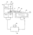
以下、図面を参照して発明を実施するための最良の形態を説明する。なお、本発明は、発明を実施するための最良の形態に限定されるものではない。図1にPET−CT装置の模式的構成を示す。本装置は本発明を実施するための最良の形態の一例である。本装置の
構成によって、医療用イメージング装置に関する発明を実施するための最良の形態の一例が示される。本装置の動作によって、テーブルシステム特定方法に関する発明を実施するための最良の形態の一例が示される。
The best mode for carrying out the invention will be described below with reference to the drawings. Note that the present invention is not limited to the best mode for carrying out the invention. FIG. 1 shows a schematic configuration of a PET-CT apparatus. This apparatus is an example of the best mode for carrying out the present invention. An example of the best mode for carrying out the invention relating to the medical imaging apparatus is shown by the configuration of the apparatus. An example of the best mode for carrying out the invention related to the table system specifying method is shown by the operation of this apparatus.
本装置は、PETガントリ(gantry)100、CTガントリ200、テーブルシステム300およびオペレータコンソール(operator console)400を有する。PETガントリ100は、テーブルシステム300によって搬入される被検体10が発生する放射線を放射線検出装置110で検出し、放射線による投影データを収集して、オペレータコンソール400に入力する。被検体10には、予め放射線発生用の医薬品が投与されている。PETガントリ100は、本発明における第1のデータ収集装置の一例である。
The apparatus includes a
CTガントリ200は、テーブルシステム300によって搬入される被検体10を、X線照射・検出装置210でスキャン(scan)し、X線による投影データを収集して、オペレータコンソール400に入力する。CTガントリ200は、本発明における第2のデータ収集装置の一例である。
The
オペレータコンソール400は、内蔵のコンピュータ(computer)により、PETガントリ100およびCTガントリ200から入力された投影データに基づいてそれぞれ画像再構成を行い、再構成した画像をディスプレイ(display)402に表示する。オペレータコンソール400は、本発明における画像再構成装置の一例である。
The
オペレータコンソール400は、PETガントリ100、CTガントリ200およびテーブルシステム300を制御する。オペレータコンソール400による制御の下で、PETガントリ100およびCTガントリ200はそれぞれデータ収集を行い、テーブルシステム300は、データ収集が所定の部位について行われるように、被検体10の位置決めを行う。テーブルシステム300は、本発明におけるテーブルシステムの一例である。
The
位置決めは、内蔵する位置調節機構により、クレードル302の水平移動距離、および、クレードル302を支持するテーブルトップ(table top)304の高さを調節することによって行われる。テーブルトップ304の高さ調節は、支柱306をベース(base)308への取り付け部を中心としてスイング(swing)させることによって行われる。
Positioning is performed by adjusting the horizontal movement distance of the
なお、テーブルシステム300は、図2に示すように、テーブルトップ304がベース308に対して垂直に昇降する方式のものであってよい。テーブルトップ304の昇降は内蔵の昇降機構によって行われる。
The
図3に、放射線検出装置110の構成を模式的に示す。図3に示すように、放射線検出装置110は、撮影中心Oと同心の円環または円筒を形成するに配列された複数の検出セル(cell)112を有し、個々の検出セル112によってそれぞれ放射線を検出するようになっている。
FIG. 3 schematically shows the configuration of the
図4に、X線照射・検出装置210の構成を模式的に示す。X線照射・検出装置210は、X線管220の焦点222から放射されたX線224をX線検出器230で検出するようになっている。
FIG. 4 schematically shows the configuration of the X-ray irradiation /
X線224は、図示しないコリメータ(collimator)で成形されてコーンビーム(cone beam)またはファンビーム(fan beam)のX線となっている。X線検出器230は、X線の広がりに対応して2次元的に広がるX線入射面232を有する。X線入射面232は円筒の一部を構成するように湾曲している。円筒の中心軸は焦点222を通る。
The
X線照射・検出装置210は、撮影中心Oを通る中心軸の周りを回転する。中心軸は、X線検出器230が形成する部分円筒の中心軸に平行である。回転の中心軸の方向をz方向とし、撮影中心Oと焦点222を結ぶ方向をy方向とし、z方向およびy方向に垂直な方向をx方向とする。これらx,y,z軸はz軸を中心軸とする回転座標系の3軸となる。
The X-ray irradiation /
図5に、X線検出器230のX線入射面232の平面図を模式的に示す。X線入射面232は検出セル234がx方向とz方向に2次元的に配置されたものとなっている。すなわち、X線入射面232は検出セル234の2次元アレイ(array)となっている。なお、ファンビームX線を用いる場合は、X線入射面232は検出セル234の1次元アレイとしてよい。
FIG. 5 schematically shows a plan view of the
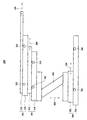
図6に、テーブルシステム300のさらに詳細な構成を模式的に示す。図6に示すように、クレードル302は、可動板322と支持部324で構成される。可動板322は、被検体を載せて支持部324の上を、矢印326で示すように、水平方向に進退可能になっている。可動板322は、本発明における可動部の一例である。矢印326は、テーブルシステム300の複数軸の1つを表す。
FIG. 6 schematically shows a more detailed configuration of the
ここでは、矢印の右向き方向をイン(in)方向、左向き方向をアウト(out)方向とする。イン方向とは、PETガントリ100またはCTガントリ200に対して被検体を搬入する方向であり、アウト方向とは搬出する方向である。
Here, the right direction of the arrow is the in direction, and the left direction is the out direction. The in direction is a direction in which the subject is carried into the
支持部324は、可動板322を移動させるための駆動機構を内蔵している。支持部324は、また、支持部324上での可動板322の絶対位置を検出するための検出器を内蔵している。そのような検出器としては、例えばエンコーダ(encoder)等が用いられる。エンコーダは、本発明における絶対位置検出手段の一例である。
The
支持部324は、さらに、2つの光学的センサ(sensor)332,334を有する。2つの光学的センサ332,334は、可動板322の移動軸に沿って所定の間隔で配置される。光学的センサ332,334は、本発明における第1の検知手段の一例である。光学的センサ332,334については後にあらためて説明する。
The
支持部324は、さらに、可動板322用のストッパ(stopper)を内蔵している。ストッパは支持部324の両端部にそれぞれ設けられ、イン方向およびアウト方向の可動板322の最大到達位置を規定するようになっている。
The
クレードル302はテーブルトップ304で支持される。テーブルトップ304は、可動板342と支持部344で構成される。可動板342は、クレードル302を載せて、矢印346で示すように支持部344の上を水平方向に進退可能になっている。可動板342にはクレードル302の支持部324が固定されている。可動板342は、本発明における可動部の一例である。矢印346は、テーブルシステム300の複数軸の1つを表す。ここでは、右方向をイン方向、左方向をアウト方向とする。
The
支持部344は、可動板342を移動させるための駆動機構を内蔵している。支持部344は、また、支持部344上での可動板342の絶対位置を検出するための検出器を内蔵している。そのような検出器としては、例えばエンコーダ等が用いられる。エンコーダは、本発明における絶対位置検出手段の一例である。
The
支持部344は、さらに、2つの光学的センサ352,354を有する。2つの光学的センサ352,354は、可動板342の移動軸に沿って所定の間隔で配置される。光学
的センサ352,354は、本発明における第1の検知手段の一例である。光学的センサ352,354については後にあらためて説明する。
The
支持部344は、さらに、可動板342用のストッパを内蔵している。ストッパは支持部344の両端部にそれぞれ設けられ、イン方向およびアウト方向の可動板342の最大到達位置を規定するようになっている。以下、テーブルトップ304をインターメディエイト・サポート(IMS)ともいう。
The
テーブルトップ304は支柱306で支持される。テーブルトップ304の支持部344が支柱306の頂部に固定されている。テーブルトップ304は、支柱306のスイングによって、矢印366で示すように垂直方向に昇降する。支柱306の角度がポテンショメータ(potentiometer)等によって検出され、その角度がテーブルトップ304の高さに換算される。矢印366は、テーブルシステム300の複数軸の1つを表す。以下、支柱306をエレベーションともいう。なお、エレベーションは、図2に示したように上下に伸縮するものであってよい。
The
支柱306はベース308で支持される。ベース308は、可動板382と支持部384で構成される。可動板382は、支柱306を載せて、矢印386で示すように支持部384の上を水平方向に進退可能になっている。支柱306の基部は可動板382に固定されている。可動板382は、本発明における可動部の一例である。矢印386は、テーブルシステム300の複数軸の1つを表す。ここでは、右方向をイン方向、左方向をアウト方向とする。
The
支持部384は、可動板382を移動させるための駆動機構を内蔵している。支持部384は、また、支持部384上での可動板382の絶対位置を検出するための検出器を内蔵している。そのような検出器としては、例えばエンコーダ等が用いられる。エンコーダは、本発明における絶対位置検出手段の一例である。
The
支持部384は、さらに、2つの光学的センサ392,394を有する。2つの光学的センサ392,394は、可動板382の移動軸に沿って所定の間隔で配置される。光学的センサ392,394は、本発明における第1の検知手段の一例である。光学的センサ392,394については後にあらためて説明する。
The
支持部384は、さらに、可動板382用のストッパを内蔵している。ストッパは支持部384の両端部にそれぞれ設けられ、イン方向およびアウト方向の可動板382の最大到達位置を規定するようになっている。以下、ベース308をトランスポータともいう。
The
トランスポータ308は、エレベーション306から上の構造物を水平方向に進退させる。エレベーション306は、IMS304から上の構造物を垂直方向に昇降させる。IMS304は、クレードル302全体を水平方向に進退させる。クレードル302は、可動板322を水平方向に進退させる。
The
トランスポータ308、IMS304およびクレードル302からなる機構の3段階の水平移動により、可動板322の総合的な移動範囲は大きなものとなる。このため、PETガントリ100およびCTガントリ200のどちらによっても、被検体を頭頂から足先まで切れ目なく撮像することが可能となる。
The total movement range of the
なお、IMS304または(および)トランスポータ308の移動を2段階以上とし、4段階以上の水平移動を可能にしてもよい。あるいは、IMS304または(および)トランスポータ308を省略して、水平移動の段階を2段階以下としてもよい。以下、水平
移動が3段階である例で説明するが、4段階以上または2段階以下の場合も同様である。
Note that the movement of the
図7に、光学的センサ332の構成例を示す。光学的センサ334,352,354,392,394も同様になっている。図7の(a)は受光タイプ(type)のセンサ、(b)は遮光タイプのセンサである。これら光学的センサは、それぞれ、本発明における光学的センサの一例である。受光タイプのセンサは、本発明における受光タイプのセンサの一例である。遮光タイプのセンサは、本発明における遮光タイプのセンサの一例である。
FIG. 7 shows a configuration example of the
(a)の受光タイプのセンサは、相対的に移動する2つの物体502,504の一方と他方に発光素子512と受光素子514をそれぞれ配置して構成される。一方の物体502は例えば可動板322,342,382であり、他方の物体504は例えば支持部324,344,384である。なお、発光素子512と受光素子514を相互に入れ替えてもよい。
The light receiving type sensor (a) is configured by arranging a
発光素子512の光が受光素子514に入射するのは、発光素子512と受光素子514とが正対する関係となったときだけである。このことを利用して、2つの物体502,504が特定の位置関係になったか否かを検知することができる。
The light from the
(b)の遮光タイプのセンサは、相対的に移動する2つの物体502,504の一方と他方に、遮光素子612とスロット(slot)素子614をそれぞれ配置して構成される。一方の物体502は例えば可動板322,342,382であり、他方の物体504は例えば支持部324,344,384である。なお、遮光素子612とスロット素子614を相互に入れ替えてもよい。
The light-shielding type sensor (b) is configured by arranging a light-shielding
遮光素子612は、2つの物体502,504の相対移動に伴ってスロット素子614のスロットを通過する。なお、2つの物体502,504の相対移動の方向は紙面に垂直な方向である。スロット素子614は、スロットを挟んで互いに対抗する発光素子642と受光素子644を有する。
The
受光素子644に入射する発光素子の642の光が遮られるのは、遮光素子612がスロット素子614のスロットに入ったときだけである。このことを利用して、2つの物体502,504が特定の位置関係になったか否かを検知することができる。
The light of the
このような光学的センサを用いることにより、2つの物体502,504が特定の位置関係になったか否かを非接触で検知することができる。光学的センサを受光タイプのセンサとすることにより、受光方式で検知することができ、遮光タイプのセンサとすることにより、遮光方式で検知することができる。
By using such an optical sensor, it is possible to detect in a non-contact manner whether or not the two
受光タイプのセンサでは、発光素子512と受光素子514のいずれか一方は、2つの物体502,504のいずれか一方に1つだけ設けられ、発光素子512と受光素子514のいずれか他方が、2つの物体502,504のいずれか他方に2つ設けられる。
In the light receiving type sensor, only one of the
すなわち、発光素子512を物体502に1つ設けるときは、受光素子514を物体504に2つ設ける。発光素子512を物体502に2つ設けるときは、受光素子514を物体504に1つ設ける。
That is, when one
発光素子512を物体504に1つ設けるときは、受光素子514を物体502に2つ設ける。発光素子512を物体504に2つ設けるときは、受光素子514を物体502に1つ設ける。発光素子にせよ受光素子にせよ、2つ設けられる素子の間隔は、予め定められた一定間隔である。
When one
遮光タイプのセンサでは、遮光素子612とスロット素子614のいずれか一方は、2つの物体502,504のいずれか一方に1つだけ設けられ、遮光素子612とスロット素子614のいずれか他方が、2つの物体502,504のいずれか他方に2つ設けられる。
In the light shielding type sensor, only one of the
すなわち、遮光素子612を物体502に1つ設けるときは、スロット素子614を物体504に2つ設ける。遮光素子612を物体502に2つ設けるときは、スロット素子614を物体504に1つ設ける。
That is, when one
遮光素子612を物体504に1つ設けるときは、スロット素子614を物体502に2つ設ける。遮光素子612を物体504に2つ設けるときは、スロット素子614を物体502に1つ設ける。遮光素子にせよスロット素子にせよ、2つ設けられる素子の間隔は、予め定められた一定間隔である。
When one
このような光学的センサを用いることにより、それぞれの軸に沿って予め設定された2つの位置における可動板322,342,382の通過をそれぞれ検知することができる。そして、そのときのエンコード信号を記憶することにより、2箇所における可動板322,342,382の位置データをそれぞれ得ることができる。
By using such an optical sensor, it is possible to detect the passage of the
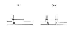
その際、位置データの精度を高めるには、例えば図8の(a)に示すように、検知信号が複数サンプリング(sampling)にわたって安定なときのエンコード信号を記憶するようにすればよい。あるいは、(b)に示すように、検知信号の立ち上がり後数サンプリングにわたって安定しているときの記憶値と、立ち下がり前数サンプリングにわたって安定しているときの記憶値との平均値を求めるようにしてもよい。 At this time, in order to increase the accuracy of the position data, for example, as shown in FIG. 8A, an encoded signal when the detection signal is stable over a plurality of samplings may be stored. Alternatively, as shown in (b), the average value of the stored value when the detection signal is stable over several samplings after the rising edge and the stored value when stable over several samplings before the falling edge is obtained. May be.
このようなテーブルシステム300を特定するプロセスについて説明する。図9および図10に、プロセスのフローチャート(flow chart)を示す。このプロセスは、オペレータコンソール400による制御の下で自動的に遂行される。オペレータコンソール400は、テーブルコントロール・ファームウェア(table control firmware)、TGP(table gantry board)ファームウェア、ホストコンピュータ(host computer)等によって、このプロセスを制御する。オペレータコンソール400は、本発明におけるテーブルシステム特定装置の一例である。
A process for specifying such a
オペレータまたはホストからの指令によってプロセスがスタート(start)すると、ステップ701で、1つの軸を選択するとともに、エレベーションをISO(isocenter)相当の高さとし、クレードル、IMSおよびトランスポータをホームポジション(home position)に移動させる。最初に選択される1つの軸は、例えばクレードルである。
When the process is started by a command from the operator or the host, in
ステップ703で、可動部をイン方向に低速で移動させる。これによって、例えばクレードル302がイン方向に低速で移動する。
ステップ705で、可動部の位置変化が十分に小さいか否かを判定する。可動部の位置変化が十分に小さくないときは、ステップ703に戻って可動部のイン方向への低速移動を継続する。可動部の位置変化が十分に小さくない間は、ステップ703,705の動作が繰り返される。
In
In
可動部がイン方向のストッパに突き当たると、可動部の移動が阻止される。このとき可動部の位置変化が十分に小さくなるので、その旨がステップ705で判定され、ステップ707で、そのときの可動部の位置データabs 3を記憶する。ステップ705における判定は、オペレータコンソール400内のコンピュータ等によって行われる。このコンピュ
ータ等は、本発明における第2の検知手段の一例である。
When the movable part hits the stopper in the in direction, the movement of the movable part is blocked. At this time, since the position change of the movable part is sufficiently small, this is determined in
次に、ステップ709で、可動部をアウト方向に低速で移動させ、ステップ711で、光学的センサの検知信号が発生したか否か判定する。光学的センサの検知信号が発生しないと判定したときは、ステップ709に戻って、アウト方向への可動部の移動を継続する。光学的センサの検知信号が発生しない間は、ステップ709,711の動作が繰り返される。
Next, in
アウト方向に移動する過程で、可動部は2つの光学的センサのうちイン側の光学的センサ(例えば、光学的センサ334)が設置されている位置を通過する。このとき光学的センサの検知信号が発生するので、その旨がステップ711で判定される。そこで、ステップ713で、そのときの可動部の位置データabs 2を記憶し、ステップ715で、アウト方向への可動部の移動を継続する。
In the process of moving in the out direction, the movable portion passes through a position where the in-side optical sensor (for example, the optical sensor 334) is installed out of the two optical sensors. At this time, since a detection signal of the optical sensor is generated, this is determined in
ステップ717で、光学的センサの検知信号が発生したか否かを判定する。光学的センサの検知信号が発生しないと判定したときは、ステップ715に戻ってアウト方向への可動部の移動を継続する。光学的センサの検知信号が発生しない間は、ステップ715,717の動作が繰り返される。
In
アウト方向に移動する過程で、可動部は2つの光学的センサのうちアウト側の光学的センサ(例えば、光学的センサ332)が設置されている位置を通過する。このとき光学的センサの検知信号が発生するので、その旨がステップ717で判定される。そこで、ステップ719で、そのときの可動部の位置データabs 1を記憶し、ステップ721で、アウト方向への可動部の移動を継続する。
In the process of moving in the out direction, the movable part passes through a position where the out-side optical sensor (for example, the optical sensor 332) of the two optical sensors is installed. At this time, since the detection signal of the optical sensor is generated, this is determined in
ステップ723で、可動部の位置変化が十分に小さいか否かを判定する。可動部の位置変化が十分に小さくないときは、ステップ721に戻って可動部のアウト方向への低速移動を継続する。可動部の位置変化が十分に小さくない間は、ステップ721,523の動作が繰り返される。
In
アウト方向において可動部がストッパに突き当たると、可動部の移動が阻止される。このとき可動部の位置変化が十分に小さくなるので、その旨がステップ723で判定され、ステップ725で、そのときの可動部の位置データabs 0を記憶する。ステップ723における判定は、オペレータコンソール400内のコンピュータ等によって行われる。このコンピュータ等は、本発明における第2の検知手段の一例である。
When the movable part hits the stopper in the out direction, the movement of the movable part is prevented. At this time, since the change in the position of the movable part is sufficiently small, this is determined in
このようにして得られた可動部位置abs0, abs 1, abs 2, abs 3のうち、可動部位置abs
1, abs 2を、ステップ727で、キャラクタライゼーション情報として記憶し、可動部位置abs , abs 3を、ステップ729で、コンフィギュレーション情報として記憶する。そして、ステップ731で、可動部をホームポジションに戻す。これで、1つの軸についてのキャラクタライゼーション情報とコンフィギュレーション情報の獲得が終わる。
Of the movable part positions abs0,
1, abs 2 are stored as characterization information in
キャラクタライゼーション情報の記憶は、例えばフラッシュメモリ(flash memory)等適宜の記憶媒体を用いて行われる。そのような記憶媒体は、本発明における第1の記憶手段の一例である。コンフィギュレーション情報の記憶は、例えばフラッシュメモリ等適宜の記憶媒体を用いて行われる。そのような記憶媒体は、本発明における第2の記憶手段の一例である。 The characterization information is stored using an appropriate storage medium such as a flash memory. Such a storage medium is an example of the first storage means in the present invention. The configuration information is stored using an appropriate storage medium such as a flash memory. Such a storage medium is an example of the second storage means in the present invention.
ステップ733で、全ての軸について完了か否かを判定し、全軸完了でないときは、ステップ701に戻る。そして、ステップ701以降の動作によって、2番目の軸(例えば
、IMS)について上記と同様な処理を行い、その軸に関するキャラクタライゼーション情報およびコンフィギュレーション情報を記憶する。トランスポータについても、同様にしてキャラクタライゼーション情報およびコンフィギュレーション情報を記憶する。
In
図11に、可動部位置abs 0, abs 1, abs 2, abs 3の関係を示す。これらはいずれもエンコーダによるハードウェアポジション(hardware position)すなわちエンコーダバリュー(encoder value)を表す。エンコーダの0位置がアウト側ストッパよりもアウト側にあるので、エンコーダバリューはオフセット(offset)を有する。
FIG. 11 shows the relationship between the movable part positions
キャラクタライゼーション情報abs 1, abs 2を用いて、エンコーダのゲインバリュー(gain value)が次式によって求められる。
Using the

ここで、Lは2つの光学的センサ間の距離であり、予め設定された既知の値である。距離Lの単位は例えばmmである。
(1)式によるゲインバリュー計算がキャラクタライゼーションの内容である。キャラクタライゼーションは、クレードル、IMSおよびトランスポータについてそれぞれ行われる。
Here, L is the distance between the two optical sensors, and is a known value set in advance. The unit of the distance L is, for example, mm.
Gain value calculation according to equation (1) is the content of characterization. Characterization is done for the cradle, IMS and transporter, respectively.
このゲインバリューを用いて、アウト側ストッパを基準とする可動部の位置が次式によって求められる。 Using this gain value, the position of the movable part with respect to the out-side stopper is obtained by the following equation.
可動部の位置は例えばmm単位で求められる。(2)式によってアウト側ストッパからイン側ストッパまでの可動部の移動距離を計算することが、コンフィギュレーション確認の内容である。コンフィギュレーション確認は、クレードル、IMSおよびトランスポータについてそれぞれ行われる。 The position of the movable part is obtained in units of mm, for example. The content of the configuration confirmation is to calculate the moving distance of the movable part from the out-side stopper to the in-side stopper using the equation (2). Configuration confirmation is performed for the cradle, IMS, and transporter, respectively.
なお、エレベーションについてのコンフィギュレーション確認は、最も降下させたときのポテンショメータの出力値および最も上昇させたときのポテンショメータの出力値をそれぞれ高さに換算することによって行われる。 Note that the configuration check for elevation is performed by converting the output value of the potentiometer when it is lowered most and the output value of the potentiometer when it is raised most into height.
ファームウェアポジション(firmware position)すなわちアウト側センサを基準とする可動部の位置は次式によって求められる。 The firmware position, that is, the position of the movable part with reference to the out-side sensor is obtained by the following equation.
なお、ファームウェアポジションのインリミット(in limit)は、テーブルシステムがPET−CTガントリとの干渉しない範囲で、オペレータにより適宜に設定される。
全軸のキャラクタライゼーション情報およびコンフィギュレーション情報を記憶したら、ステップ735で、フラグ(flag)を設定する。このフラグは、テーブルシステム特定が完了したことを表す。ステップ735におけるフラグ設定は、オペレータコンソール400内のコンピュータ等によって行われる。このコンピュータ等は、本発明におけるフラグ設定手段の一例である。このようなフラグを設定することにより、テーブルシステム特定の有無を明確にすることができる。
Note that the inlimit of the firmware position is appropriately set by the operator as long as the table system does not interfere with the PET-CT gantry.
After storing the characterization information and configuration information for all axes, a flag is set in
ステップ737で、コンフィギュレーションを表示する。表示はディスプレイ402を用いて行われる。コンフィギュレーション表示は、コンフィギュレーション情報から計算された値を用いて行われる。
In
図12に、コンフィギュレーション表示用のユーザーインターフェース(user interface)の一例を示す。このユーザーインターフェースは、本発明におけるユーザーインターフェースの一例である。 FIG. 12 shows an example of a user interface for configuration display. This user interface is an example of a user interface in the present invention.
図12に示すように、テーブルシステムの外観図と並べて、クレードル移動範囲、IMS移動範囲、エレベーション移動範囲およびトランスポータ移動範囲がそれぞれ水平なバー(bar)によって示される。各バーの両端には移動範囲の最小値と最大値がそれぞれ数字で示される。クレードルの移動範囲にオペレータによりインリミットが設定されているときは、その値も表示され、クレードルの現在位置からインリミットまでが色違い等により表示される。このように、テーブルシステムのコンフィギュレーションをユーザーインターフェースで表示することにより、コンフィグレーションの確認が容易になる。 As shown in FIG. 12, the cradle movement range, the IMS movement range, the elevation movement range, and the transporter movement range are indicated by horizontal bars in parallel with the external view of the table system. At both ends of each bar, the minimum and maximum values of the moving range are indicated by numbers. When the inlimit is set by the operator in the movement range of the cradle, the value is also displayed, and the range from the current position of the cradle to the inlimit is displayed by a different color or the like. Thus, the configuration can be easily confirmed by displaying the configuration of the table system on the user interface.
コンフィギュレーション情報は、ホストやTGP等の上位機器あるいはユーザー(user)の求めに応じて提供できるようになっている。コンフィギュレーション情報提供プロセスを図13に示す。 The configuration information can be provided in response to a request from a host device such as a host or TGP or a user. The configuration information provision process is shown in FIG.
図13に示すように、ステップ801で、コンフィギュレーション情報の問い合わせを受け取ると、ステップ803で、コンフィギュレーション情報とフラグを記憶部から読み出す。そして、ステップ805で、フラグが有効か否かを判定し、フラグが有効であるときは、ステップ807で、コンフィギュレーション情報を上位機器やユーザーに提供する。
As shown in FIG. 13, when an inquiry about configuration information is received in
フラグが有効でないと判定したときは、ステップ809で、コンフィギュレーション情報獲得を行う。コンフィギュレーション情報獲得は、図9および図10に示したプロセスによって行う。獲得したコンフィギュレーション情報がステップ807で上位機器等に提供される。
If it is determined that the flag is not valid, configuration information is acquired in
ステップ805における判定は、オペレータコンソール400内のコンピュータ等によって行われる。このコンピュータ等は、本発明における判定手段の一例である。このように、フラグの有無に基づいてテーブルシステム特定の要否を判定するので、テーブルシス
テム特定の重複を回避することができる。
The determination in
100 : PETガントリ
200 : CTガントリ
300 : テーブルシステム
400 : オペレータコンソール
402 : ディスプレイ
110 : 放射線検出装置
112 : 検出セル
210 : X線照射・検出装置
220 : X線管
222 : 焦点
224 : X線
230 : X線検出器
232 : X線入射面
234 : 検出セル
302 : クレードル
304 : テーブルトップ
306 : 支柱
308 : ベース
322,342,382 : 可動板
324,344,384 : 支持部
332,334,352,354,392,394 : 光学的センサ
502,504 : 物体
512,642 : 発光素子
514,644 : 受光素子
612 : 遮光素子
614 : スロット素子
100: PET gantry 200: CT gantry 300: Table system 400: Operator console 402: Display 110: Radiation detection device 112: Detection cell 210: X-ray irradiation / detection device 220: X-ray tube 222: Focus 224: X-ray 230: X-ray detector 232: X-ray incident surface 234: detection cell 302: cradle 304: table top 306: support column 308:
Claims (14)
前記軸のおのおのについて、
軸上の前記可動部の絶対位置を検出し、
軸に沿って予め定められた距離を隔てて設定された2つの位置における前記可動部の通過をそれぞれ光学的に検知してそのときの可動部の各絶対位置をキャラクタライゼーション情報として記憶し、
軸の両端における2つの阻止位置への前記可動部の到達をそれぞれ検知してそのときの可動部の各絶対位置をコンフィギュレーション情報として記憶する、
ことを特徴とするテーブルシステム特定方法。 In specifying a table system having a plurality of movable parts that can move independently in the respective axial directions,
For each of the axes,
Detecting the absolute position of the movable part on the axis;
Optically detecting the passage of the movable part at two positions set at a predetermined distance along the axis and storing each absolute position of the movable part at that time as characterization information;
Detecting the arrival of the movable part at two blocking positions at both ends of the shaft and storing each absolute position of the movable part at that time as configuration information;
A table system specifying method characterized by the above.
ことを特徴とする請求項1に記載のテーブルシステム特定方法。 Detecting the passage of the movable part at the two positions with optical sensors provided at the respective positions;
The table system specifying method according to claim 1.
ことを特徴とする請求項2に記載のテーブルシステム特定方法。 The optical sensor is a light receiving type sensor,
The table system specifying method according to claim 2, wherein:
ことを特徴とする請求項2に記載のテーブルシステム特定方法。 The optical sensor is a light shielding type sensor,
The table system specifying method according to claim 2, wherein:
ことを特徴とする請求項1ないし請求項4のうちのいずれか1つに記載のテーブルシステム特定方法。 A flag is set after storing the characterization information and the configuration information for all axes;
The table system specifying method according to any one of claims 1 to 4, wherein the table system specifying method is characterized in that:
ことを特徴とする請求項5に記載のテーブルシステム特定方法。 Determining the necessity of table system specification based on the presence or absence of the flag,
The table system specifying method according to claim 5.
ことを特徴とする請求項1ないし請求項6のうちのいずれか1つに記載のテーブルシステム特定方法。 Displaying the configuration of the table system on the user interface based on the configuration information;
7. The table system specifying method according to claim 1, wherein the table system specifying method is any one of claims 1 to 6.
被検体をX線でスキャンして投影データを収集する第2のデータ収集装置と、
前記第1のデータ収集装置および前記第2のデータ収集装置によってそれぞれ収集された投影データに基づいてそれぞれ画像を再構成する画像再構成装置と、
それぞれの軸方向において独立に移動可能な複数の可動部を有し、被検体を前記第1のデータ収集装置のデータ収集位置または前記第2のデータ収集装置のデータ収集位置に選択的に搬送するテーブルシステムと、
前記テーブルシステムを特定するテーブルシステム特定装置と、
を有する医療用イメージング装置であって、
前記テーブルシステム特定装置は、
前記テーブルシステムの各軸について、軸上の前記可動部の絶対位置を検出する絶対位置検出手段と、
前記テーブルシステムの各軸について、軸に沿って予め定められた距離を隔てて設定さ
れた2つの位置における前記可動部の通過をそれぞれ光学的に検知する第1の検知手段と、
前記第1の検知手段が前記可動部の通過を検知したときの可動部の各絶対位置をキャラクタライゼーション情報として記憶する第1の記憶手段と、
前記テーブルシステムの各軸について、軸の両端における2つの阻止位置への前記可動部の到達をそれぞれ検知する第2の検知手段と、
前記第2の検知手段が前記可動部の到達を検知したときの可動部の各絶対位置をコンフィギュレーション情報として記憶する第2の記憶手段と、
を有する、
ことを特徴とする医療用イメージング装置。 A first data collection device for collecting projection data by radiation generated by a pharmaceutical agent administered to a subject;
A second data acquisition device that scans a subject with X-rays and collects projection data;
An image reconstruction device for reconstructing an image based on projection data respectively collected by the first data collection device and the second data collection device;
It has a plurality of movable parts that can move independently in the respective axial directions, and selectively conveys the subject to the data collection position of the first data collection device or the data collection position of the second data collection device. Table system,
A table system specifying device for specifying the table system;
A medical imaging device comprising:
The table system specifying device is:
For each axis of the table system, absolute position detecting means for detecting the absolute position of the movable part on the axis;
For each axis of the table system, first detection means for optically detecting the passage of the movable part at two positions set at a predetermined distance along the axis;
First storage means for storing each absolute position of the movable part as characterization information when the first detection means detects passage of the movable part;
For each axis of the table system, second detection means for respectively detecting the arrival of the movable part at two blocking positions at both ends of the axis;
Second storage means for storing each absolute position of the movable part as configuration information when the second detection means detects the arrival of the movable part;
Having
A medical imaging apparatus characterized by the above.
ことを特徴とする請求項9に記載の医療用イメージング装置。 The optical sensor is a light receiving type sensor,
The medical imaging apparatus according to claim 9.
ことを特徴とする請求項9に記載の医療用イメージング装置。 The optical sensor is a light shielding type sensor,
The medical imaging apparatus according to claim 9.
ことを特徴とする請求項8ないし請求項11のうちのいずれか1つに記載の医療用イメージング装置。 The table system specifying device has flag setting means for setting a flag after storing the characterization information and the configuration information for all axes in the first storage means and the second storage means, respectively.
The medical imaging apparatus according to claim 8, wherein the medical imaging apparatus is a medical imaging apparatus.
ことを特徴とする請求項12に記載の医療用イメージング装置。 The table system specifying device includes a determination unit that determines whether table system specification is necessary based on the presence or absence of the flag.
The medical imaging apparatus according to claim 12.
ことを特徴とする請求項8ないし請求項13のうちのいずれか1つに記載の医療用イメージング装置。 The table system specifying device has a user interface for displaying a table system configuration based on the configuration information.
The medical imaging apparatus according to claim 8, wherein the medical imaging apparatus is a medical imaging apparatus.
Applications Claiming Priority (2)
| Application Number | Priority Date | Filing Date | Title |
|---|---|---|---|
| CN200610073611.4 | 2006-04-13 | ||
| CNB2006100736114A CN100512759C (en) | 2006-04-13 | 2006-04-13 | Table equipment identifying method and medical imaging equipment |
Publications (2)
| Publication Number | Publication Date |
|---|---|
| JP2007283099A true JP2007283099A (en) | 2007-11-01 |
| JP5189312B2 JP5189312B2 (en) | 2013-04-24 |
Family
ID=38646904
Family Applications (1)
| Application Number | Title | Priority Date | Filing Date |
|---|---|---|---|
| JP2007100376A Expired - Fee Related JP5189312B2 (en) | 2006-04-13 | 2007-04-06 | Table system identification method and medical imaging apparatus |
Country Status (3)
| Country | Link |
|---|---|
| US (1) | US7857513B2 (en) |
| JP (1) | JP5189312B2 (en) |
| CN (1) | CN100512759C (en) |
Cited By (3)
| Publication number | Priority date | Publication date | Assignee | Title |
|---|---|---|---|---|
| JP2009268799A (en) * | 2008-05-09 | 2009-11-19 | Toshiba Corp | X-ray ct device |
| JP2010099396A (en) * | 2008-10-27 | 2010-05-06 | Toshiba Corp | Pet-ct apparatus |
| JP2013506521A (en) * | 2009-10-06 | 2013-02-28 | コーニンクレッカ フィリップス エレクトロニクス エヌ ヴィ | Patient table with positioning system and method of using such a patient table |
Families Citing this family (13)
| Publication number | Priority date | Publication date | Assignee | Title |
|---|---|---|---|---|
| JP5670317B2 (en) * | 2009-04-22 | 2015-02-18 | 株式会社日立メディコ | Sleeper for medical imaging device |
| CN102438525B (en) * | 2010-08-04 | 2014-12-31 | 株式会社东芝 | Radiological diagnostic device and control method |
| US20120084919A1 (en) * | 2010-10-09 | 2012-04-12 | Fmi Technologies, Inc. | Patient positioning apparatus |
| CN103040482A (en) * | 2011-10-09 | 2013-04-17 | 明峰医疗系统股份有限公司 | Patient positioning apparatus |
| DE102012216303A1 (en) * | 2012-09-13 | 2014-03-13 | Siemens Aktiengesellschaft | Magnetic resonance recording unit and a magnetic resonance device with the magnetic resonance recording unit |
| CN103961133B (en) * | 2013-01-31 | 2018-09-11 | Ge医疗系统环球技术有限公司 | Patient body shape detects automatically and patient's intelligent positioning |
| KR101626760B1 (en) * | 2014-11-04 | 2016-06-02 | 삼성전자 주식회사 | Processing board, medical diagnostic apparatus, controlling method for the medical diagnostic apparatus |
| CN106137197B (en) * | 2015-01-30 | 2020-05-22 | 上海西门子医疗器械有限公司 | Vertical lifting structure, lifting bed and imaging equipment |
| JP6485410B2 (en) * | 2016-06-13 | 2019-03-20 | オムロン株式会社 | X-ray inspection apparatus and X-ray inspection method |
| US10568596B2 (en) | 2016-06-30 | 2020-02-25 | Shanghai United Imaging Healthcare Co., Ltd. | Table system and method for PET/CT imaging |
| CN106175816A (en) * | 2016-06-30 | 2016-12-07 | 上海联影医疗科技有限公司 | A kind of hospital bed device, PET/CT imaging device and method |
| JP6514756B1 (en) * | 2017-11-30 | 2019-05-15 | ゼネラル・エレクトリック・カンパニイ | Contact avoidance device, medical device, and program |
| CN114081629B (en) * | 2021-11-22 | 2023-08-29 | 武汉联影智融医疗科技有限公司 | Mobile position detection device, mobile position detection method and system registration method |
Citations (3)
| Publication number | Priority date | Publication date | Assignee | Title |
|---|---|---|---|---|
| US6349793B1 (en) * | 2000-01-27 | 2002-02-26 | Duane Kincaid | Vehicle mounted lifting apparatus and method |
| JP2004515262A (en) * | 2000-05-11 | 2004-05-27 | ヒル−ロム サービシーズ,インコーポレイティド | Automatic traction device for patient support |
| WO2006110604A2 (en) * | 2005-04-11 | 2006-10-19 | Gendex Corporation | Structural and patient positioning features of an x-ray system |
Family Cites Families (22)
| Publication number | Priority date | Publication date | Assignee | Title |
|---|---|---|---|---|
| GB1554115A (en) * | 1976-06-28 | 1979-10-17 | Ohio Nuclear | Patient support systems |
| US4236079A (en) * | 1977-12-02 | 1980-11-25 | General Electric Company | Tomographic scanning apparatus |
| DE3121728A1 (en) | 1981-06-01 | 1982-12-16 | Siemens AG, 1000 Berlin und 8000 München | PATIENT STORAGE DEVICE WITH A ROTATING STORAGE |
| US4761000A (en) | 1987-04-07 | 1988-08-02 | American Sterilizer Company | Surgical table having horizontally displaceable tabletop |
| JPH02161933A (en) * | 1988-12-16 | 1990-06-21 | Toshiba Corp | Frame device for ct |
| US5013018A (en) | 1989-06-22 | 1991-05-07 | Sicek Bernard W | Table positioning for X-ray examinations in plurality of positions |
| US5113420A (en) * | 1990-12-24 | 1992-05-12 | Texaco Inc. | Method and apparatus for positioning a sample with repeatable accuracy |
| US5541856A (en) * | 1993-11-08 | 1996-07-30 | Imaging Systems International | X-ray inspection system |
| JPH10258049A (en) * | 1997-03-19 | 1998-09-29 | Hitachi Medical Corp | Bed control device for medical diagnosing device |
| DE10029429B4 (en) | 2000-06-15 | 2004-03-04 | Siemens Ag | Operation diagnosis device with a storage device for a treatment and / or examination object |
| US6895105B2 (en) | 2000-12-21 | 2005-05-17 | General Electric Company | Imaging table sag measurement and compensation method and apparatus |
| US6928142B2 (en) * | 2002-10-18 | 2005-08-09 | Koninklijke Philips Electronics N.V. | Non-invasive plaque detection using combined nuclear medicine and x-ray system |
| JP4002165B2 (en) | 2002-11-12 | 2007-10-31 | ジーイー・メディカル・システムズ・グローバル・テクノロジー・カンパニー・エルエルシー | Table system |
| JP3859071B2 (en) | 2002-11-25 | 2006-12-20 | ジーイー・メディカル・システムズ・グローバル・テクノロジー・カンパニー・エルエルシー | Parallel link table and tomographic imaging apparatus |
| US6935779B2 (en) * | 2002-11-29 | 2005-08-30 | Ge Medical Systems Global Technology Company, Llc | Method and apparatus for aligning an X-ray source and detector at various source to image distances |
| AU2003302877A1 (en) * | 2002-12-06 | 2004-06-30 | Koninklijke Philips Electronics N.V. | X-ray system |
| US6917666B2 (en) * | 2002-12-19 | 2005-07-12 | General Electric Company | System and method for table/gantry alignment in imaging systems |
| US6857147B2 (en) | 2003-03-04 | 2005-02-22 | Ge Medical Systems Global Technology Company, Llc | Synchronization drive for a longitudinal axis telescopic guidance mechanism |
| DE10331246A1 (en) * | 2003-07-10 | 2005-02-03 | Siemens Ag | Device and method for medical procedures |
| JP4054748B2 (en) | 2003-10-21 | 2008-03-05 | ジーイー・メディカル・システムズ・グローバル・テクノロジー・カンパニー・エルエルシー | Top plate control method, patient support apparatus, and X-ray imaging apparatus |
| JP4403840B2 (en) * | 2004-03-18 | 2010-01-27 | 株式会社島津製作所 | Medical diagnostic imaging equipment |
| US7639782B2 (en) * | 2005-08-23 | 2009-12-29 | Ge Medical Systems Israel, Ltd. | Methods and systems for automatic patient table positioning |
-
2006
- 2006-04-13 CN CNB2006100736114A patent/CN100512759C/en not_active Expired - Fee Related
-
2007
- 2007-04-06 JP JP2007100376A patent/JP5189312B2/en not_active Expired - Fee Related
- 2007-04-12 US US11/734,521 patent/US7857513B2/en not_active Expired - Fee Related
Patent Citations (3)
| Publication number | Priority date | Publication date | Assignee | Title |
|---|---|---|---|---|
| US6349793B1 (en) * | 2000-01-27 | 2002-02-26 | Duane Kincaid | Vehicle mounted lifting apparatus and method |
| JP2004515262A (en) * | 2000-05-11 | 2004-05-27 | ヒル−ロム サービシーズ,インコーポレイティド | Automatic traction device for patient support |
| WO2006110604A2 (en) * | 2005-04-11 | 2006-10-19 | Gendex Corporation | Structural and patient positioning features of an x-ray system |
Cited By (3)
| Publication number | Priority date | Publication date | Assignee | Title |
|---|---|---|---|---|
| JP2009268799A (en) * | 2008-05-09 | 2009-11-19 | Toshiba Corp | X-ray ct device |
| JP2010099396A (en) * | 2008-10-27 | 2010-05-06 | Toshiba Corp | Pet-ct apparatus |
| JP2013506521A (en) * | 2009-10-06 | 2013-02-28 | コーニンクレッカ フィリップス エレクトロニクス エヌ ヴィ | Patient table with positioning system and method of using such a patient table |
Also Published As
| Publication number | Publication date |
|---|---|
| JP5189312B2 (en) | 2013-04-24 |
| US20070251008A1 (en) | 2007-11-01 |
| CN100512759C (en) | 2009-07-15 |
| CN101053524A (en) | 2007-10-17 |
| US7857513B2 (en) | 2010-12-28 |
Similar Documents
| Publication | Publication Date | Title |
|---|---|---|
| JP5189312B2 (en) | Table system identification method and medical imaging apparatus | |
| JP4782680B2 (en) | Calibration image alignment apparatus and method in PET-CT system | |
| US8873709B2 (en) | Radiographic imaging system and radiographic imaging method | |
| US20090232271A1 (en) | Radiation ct apparatus and radiation ct method | |
| US20090052617A1 (en) | Image processing method, image display method, image processing program, storage medium, image processing apparatus and X-ray imaging apparatus | |
| US20070232881A1 (en) | Method and apparatus for automatically positioning a structure within a field of view | |
| US9078618B2 (en) | Methods and systems for patient alignment for nuclear medicine imaging | |
| US11684332B2 (en) | Methods and systems for utilizing 3D sensors in nuclear medicine | |
| JPH05196738A (en) | Tomography obtaining method provided with two detectors each having sighting center different from rotary center | |
| JP2020065920A (en) | Medical diagnostic imaging apparatus, medical diagnostic imaging method, and program | |
| JP2004180846A (en) | X-ray ct apparatus | |
| JPH10268052A (en) | Method and device for forming image | |
| CN109464153B (en) | Radiation imaging system and control method thereof | |
| US8958525B2 (en) | Radiographic imaging apparatus and method | |
| JP2008029846A (en) | X-ray imaging apparatus and adjustment method of its rotary surface | |
| JP2009247391A (en) | Medical image diagnosis apparatus | |
| JP2014236922A (en) | X-ray ct apparatus, medical image diagnostic apparatus, and phantom | |
| US10674992B2 (en) | Selectable ROI and flexible detector for X-ray imaging | |
| JP2004037418A (en) | Nuclear medicine diagnostic apparatus | |
| JP2008170324A (en) | Medical image diagnosis device and nuclear medicine diagnosis device | |
| JP2005348841A (en) | Diagnostic imaging apparatus | |
| JP2001314397A (en) | Method for detecting attached attitude of phantom and its x-ray ct device | |
| JP2020075131A (en) | Calibrating x-ray medical imaging device for cephalometric imaging | |
| JP2005176896A (en) | Apparatus, method and program for processing x-ray image, and computer-readable storage medium | |
| JP2011092481A (en) | X-ray ct apparatus |
Legal Events
| Date | Code | Title | Description |
|---|---|---|---|
| A625 | Written request for application examination (by other person) |
Free format text: JAPANESE INTERMEDIATE CODE: A625 Effective date: 20100212 |
|
| RD04 | Notification of resignation of power of attorney |
Free format text: JAPANESE INTERMEDIATE CODE: A7424 Effective date: 20111114 |
|
| A131 | Notification of reasons for refusal |
Free format text: JAPANESE INTERMEDIATE CODE: A131 Effective date: 20121001 |
|
| A521 | Request for written amendment filed |
Free format text: JAPANESE INTERMEDIATE CODE: A523 Effective date: 20121206 |
|
| TRDD | Decision of grant or rejection written | ||
| A01 | Written decision to grant a patent or to grant a registration (utility model) |
Free format text: JAPANESE INTERMEDIATE CODE: A01 Effective date: 20121225 |
|
| A61 | First payment of annual fees (during grant procedure) |
Free format text: JAPANESE INTERMEDIATE CODE: A61 Effective date: 20130124 |
|
| FPAY | Renewal fee payment (event date is renewal date of database) |
Free format text: PAYMENT UNTIL: 20160201 Year of fee payment: 3 |
|
| R150 | Certificate of patent or registration of utility model |
Ref document number: 5189312 Country of ref document: JP Free format text: JAPANESE INTERMEDIATE CODE: R150 Free format text: JAPANESE INTERMEDIATE CODE: R150 |
|
| R250 | Receipt of annual fees |
Free format text: JAPANESE INTERMEDIATE CODE: R250 |
|
| R250 | Receipt of annual fees |
Free format text: JAPANESE INTERMEDIATE CODE: R250 |
|
| R250 | Receipt of annual fees |
Free format text: JAPANESE INTERMEDIATE CODE: R250 |
|
| R250 | Receipt of annual fees |
Free format text: JAPANESE INTERMEDIATE CODE: R250 |
|
| R250 | Receipt of annual fees |
Free format text: JAPANESE INTERMEDIATE CODE: R250 |
|
| R250 | Receipt of annual fees |
Free format text: JAPANESE INTERMEDIATE CODE: R250 |
|
| LAPS | Cancellation because of no payment of annual fees |