JP2007282907A - Tympanic membrane ventilation tube - Google Patents
Tympanic membrane ventilation tube Download PDFInfo
- Publication number
- JP2007282907A JP2007282907A JP2006114663A JP2006114663A JP2007282907A JP 2007282907 A JP2007282907 A JP 2007282907A JP 2006114663 A JP2006114663 A JP 2006114663A JP 2006114663 A JP2006114663 A JP 2006114663A JP 2007282907 A JP2007282907 A JP 2007282907A
- Authority
- JP
- Japan
- Prior art keywords
- pressure
- ear
- ventilation tube
- tube
- eardrum
- Prior art date
- Legal status (The legal status is an assumption and is not a legal conclusion. Google has not performed a legal analysis and makes no representation as to the accuracy of the status listed.)
- Withdrawn
Links
- 210000003454 tympanic membrane Anatomy 0.000 title claims abstract description 90
- 238000009423 ventilation Methods 0.000 title claims abstract description 79
- 210000000959 ear middle Anatomy 0.000 claims abstract description 79
- 210000000883 ear external Anatomy 0.000 claims abstract description 64
- 241000894006 Bacteria Species 0.000 abstract description 6
- 239000007788 liquid Substances 0.000 abstract description 6
- XLYOFNOQVPJJNP-UHFFFAOYSA-N water Substances O XLYOFNOQVPJJNP-UHFFFAOYSA-N 0.000 abstract description 6
- 210000002388 eustachian tube Anatomy 0.000 abstract description 5
- 238000007599 discharging Methods 0.000 abstract description 2
- 101100460844 Mus musculus Nr2f6 gene Proteins 0.000 description 34
- 102100023170 Nuclear receptor subfamily 1 group D member 1 Human genes 0.000 description 28
- RZVAJINKPMORJF-UHFFFAOYSA-N Acetaminophen Chemical compound CC(=O)NC1=CC=C(O)C=C1 RZVAJINKPMORJF-UHFFFAOYSA-N 0.000 description 12
- 210000000613 ear canal Anatomy 0.000 description 12
- 206010033078 Otitis media Diseases 0.000 description 6
- 230000004048 modification Effects 0.000 description 5
- 238000012986 modification Methods 0.000 description 5
- 229920002379 silicone rubber Polymers 0.000 description 5
- 239000004945 silicone rubber Substances 0.000 description 5
- 210000003027 ear inner Anatomy 0.000 description 4
- 210000000416 exudates and transudate Anatomy 0.000 description 4
- 239000000463 material Substances 0.000 description 4
- 230000002093 peripheral effect Effects 0.000 description 4
- 208000024891 symptom Diseases 0.000 description 4
- 230000000694 effects Effects 0.000 description 3
- 241001282135 Poromitra oscitans Species 0.000 description 2
- 206010048232 Yawning Diseases 0.000 description 2
- 239000012530 fluid Substances 0.000 description 2
- 238000003780 insertion Methods 0.000 description 2
- 230000037431 insertion Effects 0.000 description 2
- 210000003800 pharynx Anatomy 0.000 description 2
- -1 polyethylene Polymers 0.000 description 2
- 230000009747 swallowing Effects 0.000 description 2
- 230000008961 swelling Effects 0.000 description 2
- CBENFWSGALASAD-UHFFFAOYSA-N Ozone Chemical compound [O-][O+]=O CBENFWSGALASAD-UHFFFAOYSA-N 0.000 description 1
- 239000004698 Polyethylene Substances 0.000 description 1
- 239000004743 Polypropylene Substances 0.000 description 1
- RTAQQCXQSZGOHL-UHFFFAOYSA-N Titanium Chemical compound [Ti] RTAQQCXQSZGOHL-UHFFFAOYSA-N 0.000 description 1
- BZHJMEDXRYGGRV-UHFFFAOYSA-N Vinyl chloride Chemical compound ClC=C BZHJMEDXRYGGRV-UHFFFAOYSA-N 0.000 description 1
- 238000009825 accumulation Methods 0.000 description 1
- 239000003513 alkali Substances 0.000 description 1
- 230000004323 axial length Effects 0.000 description 1
- 230000015572 biosynthetic process Effects 0.000 description 1
- 230000007423 decrease Effects 0.000 description 1
- 230000008595 infiltration Effects 0.000 description 1
- 238000001764 infiltration Methods 0.000 description 1
- 229910052751 metal Inorganic materials 0.000 description 1
- 239000002184 metal Substances 0.000 description 1
- 238000000034 method Methods 0.000 description 1
- 125000002496 methyl group Chemical group [H]C([H])([H])* 0.000 description 1
- 210000005036 nerve Anatomy 0.000 description 1
- 125000001997 phenyl group Chemical group [H]C1=C([H])C([H])=C(*)C([H])=C1[H] 0.000 description 1
- 230000000704 physical effect Effects 0.000 description 1
- 229920000728 polyester Polymers 0.000 description 1
- 229920000573 polyethylene Polymers 0.000 description 1
- 229920001155 polypropylene Polymers 0.000 description 1
- 229910001220 stainless steel Inorganic materials 0.000 description 1
- 239000010935 stainless steel Substances 0.000 description 1
- 239000000126 substance Substances 0.000 description 1
- 230000009182 swimming Effects 0.000 description 1
- 229920001059 synthetic polymer Polymers 0.000 description 1
- 239000010936 titanium Substances 0.000 description 1
- 229910052719 titanium Inorganic materials 0.000 description 1
- 230000003519 ventilatory effect Effects 0.000 description 1
Images

Landscapes
- External Artificial Organs (AREA)
Abstract
Description
本発明は、鼓膜換気チューブに関する。 The present invention relates to an eardrum ventilation tube.
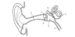
耳は、図17に示すように、外耳1、中耳2、及び内耳3で構成される。外耳1と中耳2とは、外耳道の内端に位置する鼓膜4によって仕切られている。また、中耳2が耳管5を介して咽頭に連通されている。
As shown in FIG. 17, the ear includes an
このため、鼓膜4の外側(外耳道側)と内側(内耳側)の空気圧が同じになる。このように空気圧が同じである場合、鼓膜4は張った状態に維持される。音は、空気の振動として鼓膜4を震わせる。その振動が耳小骨6に伝わって、聞こえの神経である内耳へと伝達する。
For this reason, the air pressure on the outer side (the ear canal side) and the inner side (the inner ear side) of the eardrum 4 is the same. Thus, when the air pressure is the same, the eardrum 4 is maintained in a stretched state. The sound vibrates the eardrum 4 as air vibrations. The vibration is transmitted to the
また、耳管の開大能には二種ある。一は外圧によって耳管が開大する受動的開大能であり、もう1つは嚥下やあくびによって開大する能動的開大能である。すなわち、耳管には換気機能があり、この換気機能には、嚥下やあくびによって咽頭から鼓室(中耳腔)へと空気が流入する能動的なものと、外耳の圧変化に伴って空気が流入する受動的なものとがある。 In addition, there are two types of opening ability of the eustachian tube. One is a passive opening ability that opens the ear canal by external pressure, and the other is an active opening ability that opens by swallowing or yawning. In other words, the ear canal has a ventilating function. This ventilating function includes an active one in which air flows from the pharynx to the tympanic chamber (middle ear cavity) by swallowing and yawning, and an air that changes with pressure change in the outer ear. There are passive things that flow in.
ところで、洋々な原因で、耳管5から中耳2への空気の通りが悪くなることがある。中耳2への空気の通りが悪くなると、鼓膜4の外と鼓膜4の内(中耳)の気圧に差が生じる。この場合、通常中耳2の気圧が低くなる。このため、気圧の高い方(外耳側)から低い方(中耳側)へ鼓膜4が押され、外耳側が凹む。また、中耳2が陰圧になって、この中耳2に、その周囲からの体の水分等が滲み出して溜まる。この症状が滲出性中耳炎である。
By the way, the passage of air from the
このような滲出性中耳炎に対しては、図17に示すように、鼓膜チューブと称される治療器具8を鼓膜4に留置する治療方法がある(特許文献1)。これによって、中耳腔に溜まる滲出液をこの治療器具8を介して外部(外耳側)に排出する。なお、中耳2の機能が回復したらこの治療器具8を取り去ることになる。
For such exudative otitis media, there is a treatment method in which a
また、前記のような鼓膜チューブを鼓膜4に留置させれば、中耳2と外耳1とを等しい圧力に保つことができる。
ところが、従来の鼓膜チューブは、外耳と中耳とを連通するものであるので、このような鼓膜チューブを装着している子供等がプールに入った場合には、この鼓膜チューブを介して中耳内に水が入るおそれがある。 However, since the conventional eardrum tube communicates the outer ear and the middle ear, when a child or the like wearing such a eardrum tube enters the pool, the middle ear is passed through the eardrum tube. There is a risk of water getting inside.
そこで、本発明は前述の問題点に鑑みて提案されたもので、その目的とするところは、耳管の正常な働きが回復するまでの補助的かつ生理的な役割を果たすもので、耳管が行うような換気が可能であって、しかも、外部からの水や細菌等の浸入を防止できるとともに、中耳内に滲み出した液を外部へ排出することが可能な鼓膜換気チューブを提供することにある。 Therefore, the present invention has been proposed in view of the above-mentioned problems, and its purpose is to play an auxiliary and physiological role until the normal functioning of the ear canal is restored. A tympanic membrane ventilation tube that can ventilate water and bacteria from the outside, and that can discharge the fluid that has oozed into the middle ear to the outside is provided. There is.
本発明の鼓膜換気チューブは、鼓膜に留置される鼓膜換気チューブであって、中耳と外耳との圧力差が所定圧以上で開状態となる弁手段を設けたものである。 The eardrum ventilation tube of the present invention is an eardrum ventilation tube placed in the eardrum, and is provided with valve means that is opened when the pressure difference between the middle ear and the outer ear exceeds a predetermined pressure.
本発明の鼓膜換気チューブでは、中耳と外耳との圧力差が所定圧以上となったときに、開状態となって、中耳と外耳とを等しい圧力に保つことができる。また、圧力差が所定圧未満であれば、この鼓膜換気チューブは閉状態となる。ここで、所定圧としては、例えば、100〜600daPa程度に設定することができる。 In the tympanic membrane ventilation tube of the present invention, when the pressure difference between the middle ear and the outer ear becomes equal to or higher than a predetermined pressure, the tympanic membrane ventilation tube is opened, and the middle ear and the outer ear can be kept at the same pressure. If the pressure difference is less than the predetermined pressure, the tympanic ventilation tube is closed. Here, the predetermined pressure can be set to, for example, about 100 to 600 daPa.
鼓膜に介設された孔部に嵌入されるチューブ本体を備え、スリット孔を有する円板体をチューブ本体内に固定して弁手段を構成したり、一部が前記チューブ本体に固定されてヒンジとして機能する円板体にて弁手段を構成したりすることができる。 A tube body fitted into a hole portion interposed in the eardrum, and a disc body having a slit hole is fixed in the tube body to constitute a valve means, or a part is fixed to the tube body and hinged The valve means can be constituted by a disc body that functions as:
また、中耳側の気圧が外耳側の気圧よりも高くなって開状態となる圧力差と、中耳側の気圧が外耳側の気圧よりも低くなって開状態となる圧力差とを相違させることができる。この際、圧力差が小で開状態となるときの気圧低側に膨出する弁形成板にて弁手段を構成することができる。中耳側の気圧が外耳側の気圧よりも高くなって開状態となる圧力差を、中耳側の気圧が外耳側の気圧よりも低くなって開状態となる圧力差よりも小さくしたり、大きくしりすることができる。 Also, the pressure difference that opens when the pressure on the middle ear is higher than the pressure on the outer ear is different from the pressure difference that opens when the pressure on the middle ear is lower than the pressure on the outer ear. be able to. At this time, the valve means can be constituted by a valve forming plate that bulges to the low pressure side when the pressure difference is small and the valve is open. The pressure difference that opens when the pressure on the middle ear is higher than the pressure on the outer ear, and the pressure difference that opens when the pressure on the middle ear is lower than the pressure on the outer ear, Can be bigger.
弁手段を、チューブ端部に配置したり、チューブ軸方向中央部に配置したりすることができる。 A valve means can be arrange | positioned at a tube end part, or can be arrange | positioned in a tube axial direction center part.
中耳側に配置される第1フランジと外耳側に配置される第2フランジとを備えたものであってもよい。 A first flange disposed on the middle ear side and a second flange disposed on the outer ear side may be provided.
本発明の鼓膜換気チューブは、耳管が機能せずに、中耳と外耳との圧力差が100〜600daPa圧以上となったときに、開状態となって、中耳と外耳とを等しい圧力に保つことができる。このため、鼓膜が、中耳側に膨れたり、外耳側に膨れたりすることなく、鼓膜としての機能を発揮して、音を聞き分けることができる。また、開状態となることによって、中耳内に滲み出した液の外部への排出が可能となる。 The eardrum ventilation tube of the present invention is in an open state when the pressure difference between the middle ear and the outer ear becomes 100 to 600 daPa pressure or more without the function of the ear canal, and the middle ear and the outer ear are equal in pressure. Can be kept in. Therefore, the eardrum functions as an eardrum without swelling to the middle ear side or swelling to the outer ear side, and sounds can be distinguished. In addition, by being in the open state, the liquid that has oozed into the middle ear can be discharged to the outside.
中耳と外耳との圧力差が100〜600daPa圧未満では、この鼓膜換気チューブは閉状態であるので、外部からの水や細菌等の中耳への浸入を防止できる。このため、水泳等を行った場合にも、他の耳栓等をすることなく、水の浸入を防止できる。 When the pressure difference between the middle ear and the outer ear is less than 100 to 600 daPa pressure, the tympanic membrane ventilation tube is in a closed state, so that it is possible to prevent water and bacteria from entering the middle ear from the outside. For this reason, even when swimming or the like, water can be prevented from entering without using other earplugs.
耳管の正常な働きが回復すれば取り外すことになる。このため、鼓膜換気チューブは、耳管の正常な働きが回復するまでの補助的かつ生理的な役割を果たすもので、耳管が行うような換気が可能であって、しかも、外部からの水や細菌等の浸入を防止できるとともに、中耳内に滲み出した液を外部へ排出することが可能である。 If the normal functioning of the ear canal is restored, it will be removed. For this reason, the eardrum ventilation tube plays an auxiliary and physiological role until the normal functioning of the ear canal is restored, and can be ventilated as the ear canal does. It is possible to prevent the infiltration of bacteria and bacteria, and to discharge the liquid that has oozed into the middle ear.
中耳側の気圧が外耳側の気圧よりも高くなって開状態となる圧力差と、中耳側の気圧が外耳側の気圧よりも低くなって開状態となる圧力差とを相違させることができるので、患者の症状に応じて対応することができる。すなわち、中耳側の気圧が低くなったときに、小さい圧力差で開状態としたり、逆に中耳側の気圧が高くなったときに、小さい圧力差で開状態としたりでき、さらには、中耳側の気圧が外耳側の気圧よりも高い状態を維持でき、滲出性中耳炎等が発生するのを有効に防止できるようにすることができる。 The pressure difference that opens when the pressure on the middle ear is higher than the pressure on the outer ear may be different from the pressure difference that opens when the pressure on the middle ear is lower than the pressure on the outer ear. Since it can, it can respond according to a patient's symptom. That is, when the pressure on the middle ear side becomes low, it can be opened with a small pressure difference, and conversely, when the pressure on the middle ear side becomes high, it can be opened with a small pressure difference. It is possible to maintain a state in which the pressure on the middle ear side is higher than the pressure on the outer ear side, and to effectively prevent the occurrence of exudative otitis media and the like.
中耳側に配置される第1フランジと外耳側に配置される第2フランジとを備えたものであれば、鼓膜換気チューブを安定した状態で鼓膜に留置させることができる。 If the first flange disposed on the middle ear side and the second flange disposed on the outer ear side are provided, the tympanic ventilation tube can be stably placed on the tympanic membrane.
本発明に係る鼓膜換気チューブの実施形態を以下に詳述する。 Embodiments of the tympanic ventilation tube according to the present invention will be described in detail below.
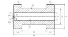
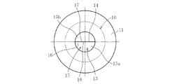
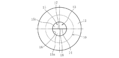
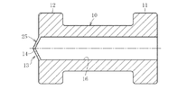
図1と図2は鼓膜換気チューブの第1実施形態を示し、この鼓膜換気チューブは、チューブ本体10と、このチューブ本体10の一方の端部に連設される第1フランジ11と、チューブ本体10の他方の端部に連設される第2フランジ12を備える。
1 and 2 show a first embodiment of an eardrum ventilation tube. The eardrum ventilation tube includes a
そして、内部に弁手段13が付設されている。この場合の弁手段13は、スリット孔14を有する円板体15からなる。すなわち、円板体15は、孔部16の第2フランジ12側の開口端に配設される。そして、円板体15は、半円板状の一対の半割体15a、15bとからなり、各半割体15a、15bの外周円弧面が孔部16の内径面に一体化され、半割体15a、15bの対応端面17、18が突き合わされて、密接している。
And valve means 13 is attached inside. The valve means 13 in this case comprises a
この場合の鼓膜換気チューブは、チューブ本体10と第1フランジ11と第2フランジ12と円板体15とが一体に成形されたシリコーンゴム(SIR)等からなる。シリコーンゴムは、無機のシロキサン結合に有機のメチル基またはフェニル基を結合させたものであり、無機と有機の中間的な構造をもっている。シリコーンゴムは使用可能温度範囲が−60℃から+180℃程度までのきわめて広範囲に及び、その範囲内における物理的性質の変化が少ない。また電気特性はNRと大差なく、使用可能温度範囲内において耐電圧の変化はほとんどない。また化学的にも安定で耐化学薬品性(濃アルカリには浸される)、耐油、耐候、耐オゾン性をもっている。
The eardrum ventilation tube in this case is made of silicone rubber (SIR) or the like in which the
このため、この鼓膜換気チューブは耐久性に優れ、しかも後述するように鼓膜4に留置させた際には、鼓膜4に馴染んで、この鼓膜換気チューブを違和感無く留置させることができる。 For this reason, this eardrum ventilation tube is excellent in durability, and when placed in the eardrum 4 as will be described later, the eardrum ventilation tube can be placed in the eardrum 4 without any discomfort.
この弁手段13においては、孔部16内と外部との圧力差が、所定圧(例えば、100〜600daPa圧)以上で、高い方側から低い方側に円板体15を押圧することになって、半割体15a、15bの対応端面17、18間に隙間が生じて開状態となる。これに対して、孔部16内と外部との圧力差が前記所定圧(例えば、100〜600daPa圧)未満の状態では、半割体15a、15bの対応端面17、18が突き合わされた状態が維持されて閉状態となっている。
In the valve means 13, the pressure difference between the inside and outside of the
鼓膜換気チューブは、例えば、その全長L1を10mmとし、フランジ間寸法L2を6mmとし、各フランジ肉厚L3、L4を2mmとし、孔部径D1を2mmとし、チューブ本体外径D2を4mmとし、フランジ外径D3を6mmとし、円板体15の肉厚Tを0.2mmとしている。また、各コーナ部には面取りが形成され、その面取りの曲率半径を0.2mmとしている。
For example, the tympanic ventilation tube has an overall length L1 of 10 mm, an inter-flange dimension L2 of 6 mm, flange thicknesses L3 and L4 of 2 mm, a hole diameter D1 of 2 mm, and a tube body outer diameter D2 of 4 mm. The outer diameter D3 of the flange is 6 mm, and the thickness T of the
前記のように構成された鼓膜換気チューブは、鼓膜4(図17参照)に留置される。すなわち、鼓膜4の一部を切開して、直線状のスリット部を形成する。そして、このスリット部を拡開させて挿通部を形成し、挿通部に鼓膜換気チューブを挿通する。この場合、第1フランジ11を中耳2側に配置するとともに、第2フランジ12を外耳1側に配置する。このように、鼓膜4を挟んで、第1フランジ11を中耳2側に配置し、第2フランジ12を外耳1側に配置することによって、この鼓膜換気チューブの鼓膜4に留置することができる。
The eardrum ventilation tube configured as described above is placed on the eardrum 4 (see FIG. 17). That is, a part of the eardrum 4 is incised to form a linear slit portion. Then, the slit portion is expanded to form an insertion portion, and the tympanic membrane ventilation tube is inserted into the insertion portion. In this case, the
本発明の鼓膜換気チューブによれば、中耳2と外耳1との圧力差が所定圧(例えば、100〜600daPa圧)以上となったときに、開状態となって、中耳2と外耳1とを等しい圧力に保つことができる。このため、耳管が行う換気機能を発揮することができ、鼓膜4が、中耳2側に膨れたり、外耳1側に膨れたりすることなく、鼓膜4としての機能を発揮して、音を聞き分けることができる。また、開状態となることによって、中耳内に滲み出した液の外部への排出が可能となって、滲出性中耳炎の治療を行うことができる。
According to the tympanic membrane ventilation tube of the present invention, when the pressure difference between the
チューブ本体10の一方の端部に連設されて中耳2側に配置される第1フランジ11(内部フランジ)と、チューブ本体10の他方の端部に連設されて外耳1側に配置される第2フランジ12(外部フランジ)とを備えているので、鼓膜換気チューブを安定した状態で鼓膜4に留置させることができる。
A first flange 11 (inner flange) arranged on one side of the tube
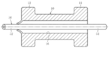
ところで、滲出性中耳炎に対しては、図3に示すように、この鼓膜換気チューブを鼓膜に装着する際に、中耳2内に滲み出した液(滲出液)を外耳1側に排出するためのドレナージチューブ(細い排出用の管)50を鼓膜換気チューブに挿通させておくのが好ましい。このドレナージチューブ50は、中耳2内の滲出液の溜まりが改善されれば(治まれば)、取り出すことになる。このため、通常は、1週間から1ヶ月程度で取り出すことになる。
By the way, for exudative otitis media, as shown in FIG. 3, when the eardrum ventilation tube is attached to the eardrum, the liquid exuded into the middle ear 2 (exudate) is discharged to the
ドレナージチューブ50の長さとしては、図3に示すように、一方のフランジ11側の端部51が中耳2内に挿入され、他方の外耳2側の端部52が外耳1側に挿入できる程度のものであればよいが、外耳1の外部開口部に達するものであってもよい。また、ドレナージチューブ50の外径としては、弁手段13のスリット孔14に挿通させることができればよく、ドレナージチューブ50の内径としては、滲出液を外耳1側に排出できるものであればよい。なお、ドレナージチューブ50の材質は、鼓膜換気チューブと同様の材質で構成することができるが、鼓膜換気チューブと相違する材質で構成してもよい。また、ドレナージチューブ50として可撓性を有していても、可撓性を有さずに常に直線状に維持されるものであってもよい。
As shown in FIG. 3, the
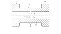
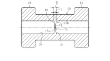
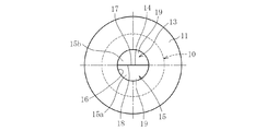
次に図4と図5は第2実施形態を示し、図6と図7は第3実施形態を示している。これらの場合、一対の半割体15a、15bからなる円板体15が、チューブ本体10の軸方向中間部に配置されている。そして、チューブ本体10の孔部16において、円板体15より第1フランジ11側と、円板体15より第2フランジ12側とで、圧力差が100〜600daPa圧未満では円板体15の半割体15a、15bの対応端面17、18が密接した閉状態となっている。圧力差が100〜600daPa圧以上生じたときには、円板体15にて構成する弁手段13が開状態となる。すなわち、円板体15の対応端面17、18との間に隙間が生じて開状態となる。
Next, FIGS. 4 and 5 show the second embodiment, and FIGS. 6 and 7 show the third embodiment. In these cases, the
図4と図5に示す鼓膜換気チューブでは、図1と図2に示す鼓膜換気チューブと同様、半割体15a、15bの肉厚を内径側と外径側とで同一に設定しているが、図6と図7に示す鼓膜換気チューブでは、各半割体15a、15bの外径部19の肉厚T1を大きく設定している。
In the tympanic ventilation tube shown in FIGS. 4 and 5, the thickness of the
図4と図5に示す鼓膜換気チューブ及び図6と図7に示す鼓膜換気チューブにおいて、他の構成は図1と図2に示す構成と同様であるので、同一部材については図1と図2と同一の符号を付してその説明を省略する。なお、図6と図7に示す鼓膜換気チューブの円板体15の外径部19の肉厚T1(最大肉厚)を0.4mmとしている。なお、円板体15の中心部の肉厚T(最小肉厚)を0.2mmとしている。また、他の寸法は前記図1と図2に示す鼓膜換気チューブと同一とした。
4 and FIG. 5 and the eardrum ventilation tube shown in FIG. 6 and FIG. 7 are otherwise the same as those shown in FIG. 1 and FIG. 2, and the same members are shown in FIG. 1 and FIG. The same reference numerals are used and the description thereof is omitted. The thickness T1 (maximum thickness) of the
このように、図4と図5に示す鼓膜換気チューブ及び図6と図7に示す鼓膜換気チューブにおいても、図1と図2に示す鼓膜換気チューブと同様の作用効果を奏する。また、図6と図7に示す鼓膜換気チューブでは、各半割体15a、15bの外径側の肉厚が大きく設定されているので、開閉に対する強度に優れる。
As described above, the tympanic ventilation tube shown in FIGS. 4 and 5 and the tympanic ventilation tube shown in FIGS. 6 and 7 also have the same effects as the tympanic ventilation tube shown in FIGS. 1 and 2. Moreover, in the tympanic membrane ventilation tube shown in FIGS. 6 and 7, since the thickness of the outer diameter side of each of the
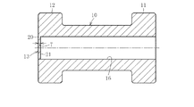
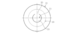
図8〜図10は第4実施形態を示し、この場合、一部がチューブ本体10に固定されてヒンジ20として機能する円板体21にて弁手段13を構成している。そして、この円板体21は孔部16の第2フランジ12側の開口端に配設される。
8 to 10 show a fourth embodiment. In this case, the valve means 13 is configured by a
弁手段13においては、孔部16内と外部との圧力差が100〜600daPa圧以上で、高い方側から低い方側に円板体15を押圧することになって、図10に示すように、円板体21がそのヒンジ20を支点として揺動し、円板体21の外周側に隙間が生じ開状態となる。また、その圧力差が100〜600daPa圧未満では、円板体21の外周縁部が孔部16の内径面に密接状となって閉状態を維持する。
In the valve means 13, the pressure difference between the inside and outside of the
図8〜図10に示す鼓膜換気チューブにおいて、他の構成は図1と図2に示す構成と同様であるので、同一部材については図1と図2と同一の符号を付してその説明を省略する。また、各寸法も図1と図2に示す鼓膜換気チューブと同一に設定される。なお、円板体21の肉厚T3も0.2mmとされる。
Since the other configurations of the tympanic membrane ventilation tube shown in FIGS. 8 to 10 are the same as those shown in FIGS. 1 and 2, the same members are denoted by the same reference numerals as those in FIGS. Omitted. Each dimension is also set to be the same as that of the eardrum ventilation tube shown in FIGS. The thickness T3 of the
このように、図8〜図10に示す鼓膜換気チューブおいても、図1と図2に示す鼓膜換気チューブと同様の作用効果を奏する。 As described above, the tympanic ventilation tube shown in FIGS. 8 to 10 has the same effect as the tympanic ventilation tube shown in FIGS. 1 and 2.
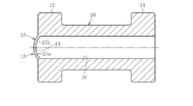
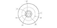
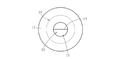
図11と図12とは第5実施形態を示し、この鼓膜換気チューブでは、外耳1側に膨出する弁形成板25にて弁手段13を構成している。この場合、弁形成板25は断面円弧状の一対の反割体25a、25bから形成している。このため、この弁形成板25にはスリット孔14が形成される。
FIG. 11 and FIG. 12 show a fifth embodiment. In this tympanic membrane ventilation tube, the valve means 13 is constituted by a
このように外部側へ膨出させることよって、外耳1側と中耳2側とで開状態となる圧力差に相違させることができる。すなわち、この鼓膜換気チューブを、第1フランジ11を中耳2側に配置し、第2フランジ12を外耳1側に配置するように装着した場合、外耳1側の気圧に対して中耳2の気圧が高くなる場合に、比較的小さい圧力差であっても開状態となり、外耳1側の気圧に対して中耳2の気圧が低くなる場合に、比較的大きな圧力差で開状態となるようにしている。このように、圧力差が小で開状態となるときの気圧低側(この場合、外耳1側)に膨出する弁形成板25にて弁手段13を構成することによって、中耳2側の気圧が外耳1側の気圧よりも高くなって開状態となる圧力差を、中耳2側の気圧が外耳1側の気圧よりも低くなって開状態となる圧力差よりも小さくすることができる。
By bulging to the outside in this way, it is possible to make a difference in pressure difference between the
また、鼓膜換気チューブを、弁形成板25が中耳2側に膨出させれば、外耳1側の気圧に対して中耳2の気圧が低くなる場合に、比較的小さい圧力差であっても開状態となり、外耳1側の気圧に対して中耳2の気圧が高くなる場合に、比較的大きな圧力差で開状態となるようできる。このため、中耳2側の気圧が外耳1側の気圧よりも高くなって開状態となる圧力差を、中耳2側の気圧が外耳1側の気圧よりも低くなって開状態となる圧力差よりも大きくすることができる。
In addition, if the tympanic ventilation tube is bulged to the
この図11と図12に示す鼓膜換気チューブでは、中耳側の気圧が外耳側の気圧よりも高くなって開状態となる圧力差と、中耳側の気圧が外耳側の気圧よりも低くなって開状態となる圧力差とを相違させることができるので、患者の症状に応じて対応することができる。すなわち、中耳側の気圧が低くなったときに、小さい圧力差で開状態としたり、逆に中耳側の気圧が高くなったときに、小さい圧力差で開状態としたりでき、さらには、中耳側の気圧が外耳側の気圧よりも高い状態を維持でき、滲出性中耳炎等が発生するのを有効に防止できるようにすることができる。 In the tympanic membrane ventilation tube shown in FIGS. 11 and 12, the pressure difference between the middle ear and the outer ear becomes higher than the pressure on the outer ear, and the pressure on the middle ear becomes lower than the pressure on the outer ear. Therefore, the pressure difference in the open state can be made different, so that it is possible to respond according to the patient's symptoms. That is, when the pressure on the middle ear side becomes low, it can be opened with a small pressure difference, and conversely, when the pressure on the middle ear side becomes high, it can be opened with a small pressure difference. It is possible to maintain a state in which the pressure on the middle ear side is higher than the pressure on the outer ear side, and to effectively prevent the occurrence of exudative otitis media and the like.
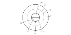
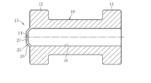
次に図13と図14とは弁形成板25の第1変形例を示し、この場合の弁形成板25は、外部側に向かって順次縮径するテーパ部26と、テーパ部26の縮径端に連設される平板部27とからなる円錐台形状体にて構成される。そして、平板部27にスリット孔14が形成される。
Next, FIGS. 13 and 14 show a first modification of the
また、図15と図16とは弁形成板25の第2変形例を示し、この場合の弁形成板25は、スリット孔14を有する円錐形状体にて構成される。
15 and 16 show a second modification of the
従って、前記第1変形例の弁形成板や第1変形例の弁形成板を使用した鼓膜換気チューブであっても、前記図11と図12に示す鼓膜換気チューブと同様、中耳2側の気圧が外耳1側の気圧よりも高くなって開状態となる圧力差と、中耳2側の気圧が外耳1側の気圧よりも低くなって開状態となる圧力差とを相違させることができる。このため、第1変形例の弁形成板や第1変形例の弁形成板を使用した鼓膜換気チューブでも、図11と図12に示す鼓膜換気チューブと同様の作用効果を奏することができる。
Therefore, even in the eardrum ventilation tube using the valve forming plate of the first modified example or the valve forming plate of the first modified example, as in the eardrum ventilating tube shown in FIGS. It is possible to make a difference between the pressure difference in which the atmospheric pressure becomes higher than the pressure on the
以上、本発明の実施形態につき説明したが、本発明は前記実施形態に限定されることなく種々の変形が可能であって、前記実施形態では、第1フランジ11を中耳2側に配置し、第2フランジ12を外耳1側に配置し、第1フランジ11を内部フランジとするとともに、第2フランジ12を外部フランジとしていたが、逆に、第2フランジ12を中耳2側に配置し、第1フランジ11を外耳1側に配置して、第1フランジ11を外部フランジとするとともに、第2フランジ12を内部フランジとするようにしてもよい。また、前記各実施形態では、第1フランジ11の径と第2フランジ12の径とを同一に設定したが、これらの径を相違させてもよい。また、各フランジ11、12を円板形状以外の種々の形状に変更することができる。要は、鼓膜4に留置させた際に、各フランジ11、12が鼓膜4に引っ掛かって、外れないものであればよい。
As described above, the embodiment of the present invention has been described. However, the present invention is not limited to the above embodiment, and various modifications are possible. In the embodiment, the
図1等の弁手段13を構成する円板体15は、一対の半割体15a、15bにて形成したものであり、スリット孔14の端部が外周縁に開口するものであったが、スリット孔14の端部が外周縁に開口しないものであってもよい。また、スリット孔14としては一本の直線状スリットに限らず、クロスする2本以上の直線状スリットにて構成してもよい。さらに、直線状スリットに限らず、曲線状のスリットであってもよい。
The
図8〜図10においては、弁手段13を構成する円板体21を、チューブ本体10の軸方向中央部に設けているが、この円板体21をチューブ本体10の軸方向端部に配置してもよい。すなわち、弁手段13を構成する円板体15、21や弁形成板25を、チューブ本体10の軸方向端部や軸方向中央部に限るものではなく、チューブ本体10の軸方向の任意の位置に設けることができる。
8 to 10, the
さらに、チューブ本体10の軸方向長さL、フランジ間寸法L2、フランジ肉厚L3、L4、孔部径D1、チューブ本体外径D2、フランジ外径D3等も、この鼓膜換気チューブを鼓膜4に留置させることができ、かつ、換気(耳管が行う能動的換気と受動的換気と同様な換気)を行うことができるとともに、中耳内に滲み出した液を外部へ排出することができる限り種々変更できる。
Further, the axial length L of the tube
鼓膜換気チューブやドレナージチューブ50の材質としては、シリコーンゴム以外のポリエステル、ポリエチレン、ポリプロピレン、塩化ビニル等の合成高分子であっても、金属(例えば、チタン、ステンレス等)であってもよい。
The material of the tympanic ventilation tube or the
弁手段13が開状態となる圧力差は、装着される患者の性別、年齢、症状等に応じて任意に設定することができるが、耳管が行うような換気が可能であって、しかも、外部からの水や細菌等の浸入を防止できるとともに、中耳内に滲み出した液を外部へ排出することができる機能を発揮する上で、前記実施形態のように、100〜600daPa圧程度が好ましく、より好ましくは、200〜300daPa圧程度である。 The pressure difference at which the valve means 13 is opened can be arbitrarily set according to the gender, age, symptom, etc. of the patient to be worn, but ventilation such as that performed by the ear canal is possible, In order to prevent the intrusion of water, bacteria, and the like from the outside and to exhibit the function of discharging the liquid that has oozed into the middle ear to the outside, the pressure of about 100 to 600 daPa is used as in the above embodiment. The pressure is preferably about 200 to 300 daPa.
1 外耳
2 中耳
3 内耳
4 鼓膜
10 チューブ本体
13 弁手段
14 スリット孔
15、21 円板体
20 ヒンジ
25 弁形成板
DESCRIPTION OF
Claims (10)
Priority Applications (1)
| Application Number | Priority Date | Filing Date | Title |
|---|---|---|---|
| JP2006114663A JP2007282907A (en) | 2006-04-18 | 2006-04-18 | Tympanic membrane ventilation tube |
Applications Claiming Priority (1)
| Application Number | Priority Date | Filing Date | Title |
|---|---|---|---|
| JP2006114663A JP2007282907A (en) | 2006-04-18 | 2006-04-18 | Tympanic membrane ventilation tube |
Publications (1)
| Publication Number | Publication Date |
|---|---|
| JP2007282907A true JP2007282907A (en) | 2007-11-01 |
Family
ID=38755206
Family Applications (1)
| Application Number | Title | Priority Date | Filing Date |
|---|---|---|---|
| JP2006114663A Withdrawn JP2007282907A (en) | 2006-04-18 | 2006-04-18 | Tympanic membrane ventilation tube |
Country Status (1)
| Country | Link |
|---|---|
| JP (1) | JP2007282907A (en) |
Cited By (2)
| Publication number | Priority date | Publication date | Assignee | Title |
|---|---|---|---|---|
| WO2019103352A1 (en) * | 2017-11-21 | 2019-05-31 | 삼성전자주식회사 | Atmospheric pressure adjustment apparatus and atmospheric pressure adjustment method of atmospheric pressure adjustment apparatus |
| WO2024253339A1 (en) * | 2023-06-07 | 2024-12-12 | 연세대학교 산학협력단 | Tympanic ventilation tube and eustachian tube plug assembly |
-
2006
- 2006-04-18 JP JP2006114663A patent/JP2007282907A/en not_active Withdrawn
Cited By (5)
| Publication number | Priority date | Publication date | Assignee | Title |
|---|---|---|---|---|
| WO2019103352A1 (en) * | 2017-11-21 | 2019-05-31 | 삼성전자주식회사 | Atmospheric pressure adjustment apparatus and atmospheric pressure adjustment method of atmospheric pressure adjustment apparatus |
| US11425509B2 (en) | 2017-11-21 | 2022-08-23 | Samsung Electronics Co., Ltd. | Atmospheric pressure adjustment apparatus and atmospheric pressure adjustment method of atmospheric pressure adjustment apparatus |
| WO2024253339A1 (en) * | 2023-06-07 | 2024-12-12 | 연세대학교 산학협력단 | Tympanic ventilation tube and eustachian tube plug assembly |
| KR20240173987A (en) * | 2023-06-07 | 2024-12-16 | 연세대학교 산학협력단 | Tympanic ventilation tube and eustachian tube plug assembly |
| KR102878367B1 (en) | 2023-06-07 | 2025-10-28 | 연세대학교 산학협력단 | Tympanic ventilation tube and eustachian tube plug assembly |
Similar Documents
| Publication | Publication Date | Title |
|---|---|---|
| US10440458B2 (en) | Comfort and high retention vibration and sound damping ear tips | |
| US7313245B1 (en) | Intracanal cap for canal hearing devices | |
| US11471331B2 (en) | Earplug for selective attenuation of sound and an insert with an acoustic filter for use in an earplug | |
| US8150082B2 (en) | Waterproof hearing aid | |
| JP2021517500A5 (en) | Ear tips and earphone systems | |
| KR101608790B1 (en) | Music earphone | |
| US20160269823A1 (en) | Waterproof earphone structure | |
| JP2009540768A (en) | Sealing holder for long-term hearing devices | |
| US20230007416A1 (en) | Multiple flexible tips for a hearing assistance device | |
| BRPI1008206B1 (en) | ear protector | |
| DE112006000463T5 (en) | Waterproof hearing aid | |
| WO2004060016A3 (en) | Hearing aid | |
| WO2018071201A1 (en) | Hearing protection devices and attenuation button for same | |
| CN101297593B (en) | Hearing devices containing open earplugs with short release devices | |
| JP5894322B1 (en) | Simple hearing aid | |
| US9237968B1 (en) | Water sports ear plug | |
| US20150059776A1 (en) | Earplug | |
| CN205987277U (en) | An ear -worn earphone | |
| JP5164652B2 (en) | hearing aid | |
| CN104138305A (en) | Noise canceling earplugs without tinnitus | |
| CN104159547B (en) | Hearing aid molded body | |
| KR200431196Y1 (en) | Hearing protection. | |
| US886790A (en) | Ear-stopple. | |
| DE102022207352A1 (en) | hearing aid | |
| JP2008048303A (en) | Electroacoustic transducer and its attachment |
Legal Events
| Date | Code | Title | Description |
|---|---|---|---|
| A300 | Application deemed to be withdrawn because no request for examination was validly filed |
Free format text: JAPANESE INTERMEDIATE CODE: A300 Effective date: 20090707 |