JP2007276754A - Rolling front suspension - Google Patents
Rolling front suspension Download PDFInfo
- Publication number
- JP2007276754A JP2007276754A JP2006129577A JP2006129577A JP2007276754A JP 2007276754 A JP2007276754 A JP 2007276754A JP 2006129577 A JP2006129577 A JP 2006129577A JP 2006129577 A JP2006129577 A JP 2006129577A JP 2007276754 A JP2007276754 A JP 2007276754A
- Authority
- JP
- Japan
- Prior art keywords
- handle
- rolling
- horizontal direction
- front suspension
- spindle shaft
- Prior art date
- Legal status (The legal status is an assumption and is not a legal conclusion. Google has not performed a legal analysis and makes no representation as to the accuracy of the status listed.)
- Pending
Links
Images


Abstract
Description
本発明はエンジンを駆動源として雪原もしくは雪面を走らせることのできる雪上車のフロントサスペンションに関するものである。The present invention relates to a front suspension of a snow vehicle capable of running on a snowy field or a snow surface using an engine as a drive source.
エンジンの動力で走行する雪上車において、フロントサスペンションについて各種の提案がなされてきた(例えば、特許文献1)。Various proposals have been made for front suspensions in snow vehicles that run on engine power (for example, Patent Document 1).
車体前部に配されたフロントサスペンションは、走行中に雪面の凸凹をフロントダンパーによってショックを吸収する機構を持っているが、傾斜地を水平方向に走行する際、車体のフロントダンパーは、ほとんど動くことは無くダンパーは伸びきった状態であり前部が重たい車体は谷側にローリングをし、流れ落ちる習性を持っている。The front suspension at the front of the vehicle has a mechanism that absorbs shocks on the uneven surface of the snow surface by the front damper while driving, but the vehicle's front damper moves almost when traveling horizontally on sloping ground. There is nothing, the damper is in a fully extended state, and the body with a heavy front part rolls to the valley side and has the habit of flowing down.
上述のように操舵機構が左右一対のスキーだけで操舵する場合は、平坦の雪原もしくは雪面を走行する事に支障は無いが、傾斜地を水平方向に走行するとき傾斜角度に対し平行に走行しようとするが、車体が谷方向にローリングするため操縦機能としては、傾斜地を水平方向に操縦することが容易ではないと言う問題が生ずる。As described above, when the steering mechanism is steered only by a pair of left and right skis, there is no problem in traveling on a flat snowy field or surface, but when traveling horizontally on a sloping ground, try to travel parallel to the slant angle. However, since the vehicle body rolls in the valley direction, a problem arises that it is not easy to steer the sloped land in the horizontal direction.
雪上車の固定型ハンドルポストから可到式ハンドルポストへの改良、メインフレームに固定されていたフロントサスペンションをローリング式フロントサスペンションの新機構を取り入れそれを支持するためにメインフレーム前部にスピンドルシャフトを配備し、補強を取るためにメインフレームからスピンドルシャフトへ伸びるサブフレームを配備した事が特徴の雪上車。Improvement of snow vehicle from fixed handle post to reachable handle post, front suspension fixed to main frame adopts a new mechanism of rolling type front suspension and a spindle shaft at the front of main frame to support it A snow vehicle that features a subframe that extends from the main frame to the spindle shaft for deployment and reinforcement.
本発明は雪上車が雪原もしくは雪面の傾斜地を水平方向に走行させる為に、ローリング式フロントサスペンションを車体前部に配備し車体上部にあるハンドルを山側に倒すことにより、山側のスキーは、上昇移動し、谷側のスキーは下降移動する為、雪上車は車体を水平に保つことが出来さらに、左右一対のスキーは傾斜面に対して平行に接地している事から、傾斜地を水平走行する際、谷方向へのローリングを抑え走行することが出来る事を特徴とする。In the present invention, in order for a snow vehicle to travel horizontally on a snowy field or a sloping surface of the snow surface, a rolling front suspension is arranged at the front of the vehicle body and the handle at the top of the vehicle body is tilted to the mountain side, so that the ski on the mountain side rises. Since the ski on the valley side moves down, the snowmobile can keep the vehicle body level, and the pair of left and right skis are grounded parallel to the inclined surface, so it runs horizontally on the slope. At the time, it is characterized by being able to run while suppressing rolling in the valley direction.
本発明を実施するための最良の形態を添付図に基づいて以下に説明する。なお、図面は符号の向きに見るものとする。また、Lは運転者から見て左、Rは同右を表す添え字である。The best mode for carrying out the present invention will be described below with reference to the accompanying drawings. The drawings are viewed in the direction of the reference numerals. Further, L is a subscript indicating the left when viewed from the driver, and R is a subscript indicating the right.
図1は本発明に係わる雪上車の全体側面図であり、雪上車1は車体2に前から後ろへ、左右一対のスキー5L、5R(5Rは5Lの影。以下同様)エンジン9及びトラックベルト8をこの順に備え、エンジン9の動力でトラックベルト8を駆動することで走行し、スキー5L、5Rをハンドル4で操作する事によって、操舵することの出来る雪上乗り物である。操舵系統の構成は別図で詳しく説明する。FIG. 1 is an overall side view of a snow vehicle according to the present invention. The snow vehicle 1 has a pair of left and
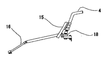
図2は本発明に係わる雪上車のローリング式フロントサスペンション14と可倒式ハンドルポスト15とハンドル4であり、車体2前部のフレーム7(図1・図4)に配されたスピンドルシャフト17にローリング式フロントアクスル14を配し、可倒式ハンドルポスト15がハンドル4を介して、ハンドル4を前後方向に対し左右に倒す事により、クロスジョイントギヤーシャフト16がフロントアクスルギヤー20を左右に駆動させて、フロントアクスル14全体が、スピンドルシャフト17を介し、回転することによりローリング式フロントサスペンション14は左右両端のスキー5L、5Rが上下駆動する構造を持っている。本発明の雪上車は傾斜地水平方向で車体を水平に保つことが出来、さらに左右一対のスキー5L、5Rは傾斜地水平方向の傾斜面に対して平行に接地している事から、傾斜地水平方向を水平走行する際、谷方向へのローリングを抑え走行することが出来る事を特徴とする。従ってこの雪上車は、傾斜地を無理なくスムーズに、水平方向に走行する事が出来る。FIG. 2 shows a
図3は本発明に係わる雪上車のローリング式フロントサスペンション14と可倒式ハンドルポスト15とハンドル4を上から見た上面図であり、車体2に備わるハンドル4は左右に回転し、プッシュロッド21を介して操向スキー5L、5Rがハンドル4操作によって左右に操舵される。ハンドル4を支持している可倒式ハンドルポスト15は、ハンドル4を介して左右に倒すことにより、クロスジョイントギヤーシャフト16が左右に回転する。クロスジョイントギヤーシャフト16の先端部には、ギヤーが備わっておりローリング式フロントサスペンション14の上部にフロントアクスルギヤー20と噛み合いローリング式フロントサスペンション14はスピンドルシャフト17を中心に左右に回転し、ローリング式フロントサスペンション14は左右両端のスキー5L、5Rを上下駆動する事が出来る構造である。FIG. 3 is a top view of the
図4は本発明に係わる雪上車のメインフレーム7と、サブフレーム19及びスピンドルシャフト17を斜め前から見た斜視図でありメインフレーム7の前部にスピンドルシャフト17を接続しサブフレーム19で補強している。スピンドルシャフト17にローリング式フロントサスペンション14が差し込まれ、スピンドルシャフト17上で、ローリング式フロントサスペンション14が回転する構造である。FIG. 4 is a perspective view of the
図5は、本発明に係わる雪上車のユニバーサルレベルアーム18の側面図である。ユニバーサルレベルアーム18は、可倒式ハンドルポスト15を倒したとき、ユニバーサルジョイントを介してハンドル4の回転をスムーズに伝達し、操向スキー5L、5Rの操縦を、そして、ローリング式フロントサスペンション14の回転も同時に出来るような構造となっている。FIG. 5 is a side view of the
本発明は雪面若しくは雪原を走行する雪上車に好適である。The present invention is suitable for a snow vehicle traveling on a snow surface or a snowy field.
1:スノーモービル 2:車体
3:カウリング 4:ハンドル
5L/5R:操向スキー 6:シート
7:メインフレーム 8:リヤサスペンション
9:エンジン 10:排気管
11:マフラー 12:エアークリーナー
13:ダンパー、 14:ローリング式フロントサスペンション
15:可倒式ハンドルポスト 16:クロスジョイントギヤーシャフト
17:スピンドルシャフト 18:ユニバーサルレベルアーム
19:サブフレーム 20:フロントアクスルギヤー
21:プッシュロッド1: Snowmobile 2: Car body 3: Cowling 4:
Claims (2)
Priority Applications (1)
| Application Number | Priority Date | Filing Date | Title |
|---|---|---|---|
| JP2006129577A JP2007276754A (en) | 2006-04-05 | 2006-04-05 | Rolling front suspension |
Applications Claiming Priority (1)
| Application Number | Priority Date | Filing Date | Title |
|---|---|---|---|
| JP2006129577A JP2007276754A (en) | 2006-04-05 | 2006-04-05 | Rolling front suspension |
Publications (1)
| Publication Number | Publication Date |
|---|---|
| JP2007276754A true JP2007276754A (en) | 2007-10-25 |
Family
ID=38678657
Family Applications (1)
| Application Number | Title | Priority Date | Filing Date |
|---|---|---|---|
| JP2006129577A Pending JP2007276754A (en) | 2006-04-05 | 2006-04-05 | Rolling front suspension |
Country Status (1)
| Country | Link |
|---|---|
| JP (1) | JP2007276754A (en) |
Cited By (1)
| Publication number | Priority date | Publication date | Assignee | Title |
|---|---|---|---|---|
| CN105008152A (en) * | 2013-03-07 | 2015-10-28 | 北极星工业有限公司 | Utility vehicle |
-
2006
- 2006-04-05 JP JP2006129577A patent/JP2007276754A/en active Pending
Cited By (2)
| Publication number | Priority date | Publication date | Assignee | Title |
|---|---|---|---|---|
| CN105008152A (en) * | 2013-03-07 | 2015-10-28 | 北极星工业有限公司 | Utility vehicle |
| CN105008152B (en) * | 2013-03-07 | 2018-09-11 | 北极星工业有限公司 | Multifunctional vehicle |
Similar Documents
| Publication | Publication Date | Title |
|---|---|---|
| ES2686142T3 (en) | Vehicle with tilting frame | |
| CN102470909B (en) | Control system for leaning vehicle | |
| JP5005546B2 (en) | Tracked all-terrain vehicle | |
| JP3743762B1 (en) | Front two-wheeled vehicle | |
| CN100448736C (en) | Laterally-leaning four wheeled vehicle | |
| US7753155B2 (en) | Front drive system for a snowmobile | |
| TW200824932A (en) | Amphibious vehicle | |
| CN105829201A (en) | Tilting mechanism for a multi-wheeled tilting vehicle | |
| JPH0440240B2 (en) | ||
| JP2010501397A5 (en) | ||
| JP2009526681A (en) | Vehicles that lean on curves, especially tricycles | |
| WO2006066406A1 (en) | Endless belt drive for vehicle | |
| JPS59120504A (en) | Four-wheel-drive motor vehicle | |
| JP2010509110A (en) | Amphibious vehicle | |
| JPH0647387B2 (en) | Four-wheel drive vehicle | |
| US3893533A (en) | Recreational vehicle | |
| WO1999041136A1 (en) | A three-wheeled car frame capable of inclining when handling a curve | |
| JP2009507703A (en) | Truck-type vehicles, especially snow scooters | |
| JP2011111002A (en) | Motor-driven rough terrain traveling vehicle | |
| JP2003154988A (en) | Ski part structure of snow mobile | |
| JP2007276754A (en) | Rolling front suspension | |
| US9193235B2 (en) | Stable high-speed utility vehicle | |
| JPH0781696A (en) | Off-road travel car | |
| JP5563924B2 (en) | Amphibious vehicle | |
| CN205872159U (en) | Novel track snowmobile |