JP2007275573A - Angle variable fastener, kit, and method for preliminary setting of nail assembly - Google Patents
Angle variable fastener, kit, and method for preliminary setting of nail assembly Download PDFInfo
- Publication number
- JP2007275573A JP2007275573A JP2007092167A JP2007092167A JP2007275573A JP 2007275573 A JP2007275573 A JP 2007275573A JP 2007092167 A JP2007092167 A JP 2007092167A JP 2007092167 A JP2007092167 A JP 2007092167A JP 2007275573 A JP2007275573 A JP 2007275573A
- Authority
- JP
- Japan
- Prior art keywords
- nail
- screw
- fixture
- opening
- assembly
- Prior art date
- Legal status (The legal status is an assumption and is not a legal conclusion. Google has not performed a legal analysis and makes no representation as to the accuracy of the status listed.)
- Pending
Links
- 238000000034 method Methods 0.000 title description 56
- 238000011882 arthroplasty Methods 0.000 claims description 3
- 210000000988 bone and bone Anatomy 0.000 description 84
- 210000000689 upper leg Anatomy 0.000 description 63
- 239000007943 implant Substances 0.000 description 50
- 206010017076 Fracture Diseases 0.000 description 41
- 208000010392 Bone Fractures Diseases 0.000 description 27
- 230000001054 cortical effect Effects 0.000 description 23
- 210000002436 femur neck Anatomy 0.000 description 21
- 210000001699 lower leg Anatomy 0.000 description 21
- 210000000527 greater trochanter Anatomy 0.000 description 18
- 210000000528 lesser trochanter Anatomy 0.000 description 18
- 230000008901 benefit Effects 0.000 description 15
- 208000014674 injury Diseases 0.000 description 13
- 230000008733 trauma Effects 0.000 description 13
- 230000006835 compression Effects 0.000 description 12
- 238000007906 compression Methods 0.000 description 12
- 238000001356 surgical procedure Methods 0.000 description 11
- 210000002303 tibia Anatomy 0.000 description 8
- 239000008186 active pharmaceutical agent Substances 0.000 description 6
- 239000003795 chemical substances by application Substances 0.000 description 5
- 208000008924 Femoral Fractures Diseases 0.000 description 4
- 238000002513 implantation Methods 0.000 description 4
- 230000000399 orthopedic effect Effects 0.000 description 4
- 210000003484 anatomy Anatomy 0.000 description 3
- 230000000712 assembly Effects 0.000 description 3
- 238000000429 assembly Methods 0.000 description 3
- 238000010586 diagram Methods 0.000 description 3
- 208000020089 femoral neck fracture Diseases 0.000 description 3
- 230000004927 fusion Effects 0.000 description 3
- 210000002758 humerus Anatomy 0.000 description 3
- 239000000463 material Substances 0.000 description 3
- 229910052751 metal Inorganic materials 0.000 description 3
- 239000002184 metal Substances 0.000 description 3
- 239000007787 solid Substances 0.000 description 3
- 230000008878 coupling Effects 0.000 description 2
- 238000010168 coupling process Methods 0.000 description 2
- 238000005859 coupling reaction Methods 0.000 description 2
- 230000005484 gravity Effects 0.000 description 2
- 230000007246 mechanism Effects 0.000 description 2
- 210000002320 radius Anatomy 0.000 description 2
- 229910000684 Cobalt-chrome Inorganic materials 0.000 description 1
- 206010020100 Hip fracture Diseases 0.000 description 1
- 229910001069 Ti alloy Inorganic materials 0.000 description 1
- RTAQQCXQSZGOHL-UHFFFAOYSA-N Titanium Chemical compound [Ti] RTAQQCXQSZGOHL-UHFFFAOYSA-N 0.000 description 1
- WAIPAZQMEIHHTJ-UHFFFAOYSA-N [Cr].[Co] Chemical class [Cr].[Co] WAIPAZQMEIHHTJ-UHFFFAOYSA-N 0.000 description 1
- 238000005452 bending Methods 0.000 description 1
- 230000008859 change Effects 0.000 description 1
- 239000010952 cobalt-chrome Substances 0.000 description 1
- 239000002131 composite material Substances 0.000 description 1
- 238000011109 contamination Methods 0.000 description 1
- 210000003275 diaphysis Anatomy 0.000 description 1
- 238000005553 drilling Methods 0.000 description 1
- 210000000501 femur body Anatomy 0.000 description 1
- 230000035876 healing Effects 0.000 description 1
- 238000003780 insertion Methods 0.000 description 1
- 230000037431 insertion Effects 0.000 description 1
- 230000003993 interaction Effects 0.000 description 1
- 210000003127 knee Anatomy 0.000 description 1
- 230000003902 lesion Effects 0.000 description 1
- 238000004519 manufacturing process Methods 0.000 description 1
- 230000000149 penetrating effect Effects 0.000 description 1
- 239000004033 plastic Substances 0.000 description 1
- 230000009467 reduction Effects 0.000 description 1
- 230000008439 repair process Effects 0.000 description 1
- 238000010079 rubber tapping Methods 0.000 description 1
- 210000004872 soft tissue Anatomy 0.000 description 1
- 229910001220 stainless steel Inorganic materials 0.000 description 1
- 239000010935 stainless steel Substances 0.000 description 1
- 229910001256 stainless steel alloy Inorganic materials 0.000 description 1
- 238000006467 substitution reaction Methods 0.000 description 1
- 229910052719 titanium Inorganic materials 0.000 description 1
- 239000010936 titanium Substances 0.000 description 1
- 210000000623 ulna Anatomy 0.000 description 1
Images


Classifications
-
- A—HUMAN NECESSITIES
- A61—MEDICAL OR VETERINARY SCIENCE; HYGIENE
- A61B—DIAGNOSIS; SURGERY; IDENTIFICATION
- A61B17/00—Surgical instruments, devices or methods, e.g. tourniquets
- A61B17/56—Surgical instruments or methods for treatment of bones or joints; Devices specially adapted therefor
- A61B17/58—Surgical instruments or methods for treatment of bones or joints; Devices specially adapted therefor for osteosynthesis, e.g. bone plates, screws, setting implements or the like
- A61B17/68—Internal fixation devices, including fasteners and spinal fixators, even if a part thereof projects from the skin
- A61B17/74—Devices for the head or neck or trochanter of the femur
- A61B17/742—Devices for the head or neck or trochanter of the femur having one or more longitudinal elements oriented along or parallel to the axis of the neck
- A61B17/744—Devices for the head or neck or trochanter of the femur having one or more longitudinal elements oriented along or parallel to the axis of the neck the longitudinal elements coupled to an intramedullary nail
-
- A—HUMAN NECESSITIES
- A61—MEDICAL OR VETERINARY SCIENCE; HYGIENE
- A61B—DIAGNOSIS; SURGERY; IDENTIFICATION
- A61B17/00—Surgical instruments, devices or methods, e.g. tourniquets
- A61B17/56—Surgical instruments or methods for treatment of bones or joints; Devices specially adapted therefor
- A61B17/58—Surgical instruments or methods for treatment of bones or joints; Devices specially adapted therefor for osteosynthesis, e.g. bone plates, screws, setting implements or the like
- A61B17/68—Internal fixation devices, including fasteners and spinal fixators, even if a part thereof projects from the skin
- A61B17/74—Devices for the head or neck or trochanter of the femur
- A61B17/742—Devices for the head or neck or trochanter of the femur having one or more longitudinal elements oriented along or parallel to the axis of the neck
- A61B17/748—Devices for the head or neck or trochanter of the femur having one or more longitudinal elements oriented along or parallel to the axis of the neck with means for adapting the angle between the longitudinal elements and the shaft axis of the femur
-
- A—HUMAN NECESSITIES
- A61—MEDICAL OR VETERINARY SCIENCE; HYGIENE
- A61B—DIAGNOSIS; SURGERY; IDENTIFICATION
- A61B17/00—Surgical instruments, devices or methods, e.g. tourniquets
- A61B17/56—Surgical instruments or methods for treatment of bones or joints; Devices specially adapted therefor
- A61B17/58—Surgical instruments or methods for treatment of bones or joints; Devices specially adapted therefor for osteosynthesis, e.g. bone plates, screws, setting implements or the like
- A61B17/68—Internal fixation devices, including fasteners and spinal fixators, even if a part thereof projects from the skin
- A61B17/72—Intramedullary pins, nails or other devices
- A61B17/7233—Intramedullary pins, nails or other devices with special means of locking the nail to the bone
- A61B17/7241—Intramedullary pins, nails or other devices with special means of locking the nail to the bone the nail having separate elements through which screws pass
Abstract
Description
〔発明の分野〕
本発明は、概して、整形外科の分野に関し、詳細には、整形外科的外傷または整形外科関節部品に用いるためにプロテーゼコンポーネントを骨に固定するための装置に関する。
(Field of the Invention)
The present invention relates generally to the field of orthopedics and, more particularly, to an apparatus for securing a prosthetic component to bone for use in an orthopedic trauma or orthopedic joint component.
〔関連出願〕
以下の出願について、相互参照がなされる。
1.代理人整理番号:DEP5517USNP、名称:「髄内釘インプラント組立体、キット、および方法(INTRAMEDULLARY NAIL IMPLANT ASSEMBLY, KIT AND METHOD)」
2.代理人整理番号:DEP5720USNP、名称:「髄内釘、髄内釘組立体、および方法(INTRAMEDULLARY NAIL, INTRAMEDULLARY NAIL ASSEMBLY AND METHOD)」
3.代理人整理番号:DEP5721USNP、名称:「固定具、髄内釘キット、および釘組立体を事前に設定する方法(FIXTURE, INTRAMEDULLARY NAIL KIT AND METHOD OF PRESETTING A NAIL ASSEMBLY)」
4.代理人整理番号:DEP5654USNP、名称:「可変角髄内釘、キット、および方法(VARIABLE ANGLE INTRAMEDULLARY NAIL, KIT AND METHOD)」
5.代理人整理番号:DEP5722USNP、名称:「可変角髄内釘、組立体、および方法(VARIABLE ANGLE INTRAMEDULLARY NAIL, ASSEMBLY AND METHOD)」
本願と同時出願のこれらの特許文献は、参照して本明細書に組み入れる。
[Related applications]
Cross references are made to the following applications:
1. Agent reference number: DEP5517USNP, name: “INTRAMEDULLARY NAIL IMPLANT ASSEMBLY, KIT AND METHOD”
2. Agent reference number: DEP5720USNP, Name: “Intramedullary nail, intramedullary nail assembly and method (INTRAMEDULLARY NAIL, INTRAMEDULLARY NAIL ASSEMBLY AND METHOD)”
3. Agent reference number: DEP5721USNP, name: “FIXTURE, INTRAMEDULLARY NAIL KIT AND METHOD OF PRESETTING A NAIL ASSEMBLY”
4). Agent reference number: DEP5654USNP, Name: “VARIABLE ANGLE INTRAMEDULLARY NAIL, KIT AND METHOD”
5). Agent reference number: DEP5722USNP, name: “VARIABLE ANGLE INTRAMEDULLARY NAIL, ASSEMBLY AND METHOD”
These patent applications filed concurrently with the present application are incorporated herein by reference.
〔発明の背景〕
骨格系は、人間の胴から延びる多数の長骨を含む。このような長骨には、大腿骨、腓骨、脛骨、上腕骨、橈骨、および尺骨が含まれる。これらの長骨は、特に、事故によって外傷を受けやすく、このような外傷で骨折することがよくあり、重度な複雑骨折をすることもある。
BACKGROUND OF THE INVENTION
The skeletal system includes a number of long bones that extend from the human torso. Such long bones include the femur, radius, tibia, humerus, radius, and ulna. These long bones are particularly susceptible to trauma from accidents, and are often fractured by such trauma, and can result in severe complex fractures.
例えば自動車事故が、長骨の外傷の一般的な原因である。具体的には、正面衝突で膝の周囲の領域が当たると、大腿骨および脛骨が骨折することがよくある。 For example, car accidents are a common cause of long bone trauma. Specifically, the femur and tibia often break when a frontal collision hits the area around the knee.
例えば大腿骨や脛骨などの長骨の遠位端部または近位部分は、骨折して複数に分離することがよくあり、再整合しなければならない。通常は、ピン、プレート、ネジ、釘、ワイヤ、および外部装置の形態である機械装置が、骨折した長骨を取り付けるために一般に用いられている。ピン、プレート、ワイヤ、釘、およびネジは通常、例えば、チタン、ステンレス鋼、またはコバルトクロムなどの人体に適合性である耐久材料から形成されている。 For example, the distal end or proximal portion of a long bone, such as the femur or tibia, is often fractured and separated into multiple pieces and must be realigned. Mechanical devices, usually in the form of pins, plates, screws, nails, wires, and external devices are commonly used to attach fractured long bones. Pins, plates, wires, nails, and screws are typically formed from durable materials that are compatible with the human body, such as, for example, titanium, stainless steel, or cobalt chrome.
長骨の骨折部は通常、3つの可能な技術の少なくとも1つによって所定の位置に固定される。 Long bone fractures are typically fixed in place by at least one of three possible techniques.
第1の方法は、骨折した骨の部分の髄管内に配置する髄内釘を用いることである。 The first method is to use an intramedullary nail that is placed in the medullary canal of the portion of the fractured bone.
骨折した骨を修復するための第2の方法は、内部骨プレートを用いることである。この内部骨プレートは、軟組織の下側の骨の外側に配置され、骨の骨折部分をブリッジする。 A second method for repairing fractured bone is to use an internal bone plate. This internal bone plate is placed outside the lower bone of soft tissue and bridges the fractured portion of the bone.
骨折した骨を所定の位置に固定するための別の方法は、外部固定装置を用いることである。このような外部固定装置は、少なくとも2つに大きく分類できる。1つの分類では、固定装置は、概ね線形であって、骨の第1の骨折部分に連結するための第1の部分と、骨の第2の骨折部分に連結するための第2の部分を備えている。第1の一連の骨ネジまたはピンが、まず固定装置に連結され、次に骨の第1の部分に連結される。次に、第2の一連のネジまたはピンが、固定装置に連結され、次に、骨の第2の骨折部分に連結される。したがって、骨の第1の部分の骨折部分が、骨の第2の部分に固定される。 Another way to fix the fractured bone in place is to use an external fixation device. Such external fixing devices can be broadly classified into at least two. In one class, the fixation device is generally linear and includes a first portion for coupling to the first fracture portion of the bone and a second portion for coupling to the second fracture portion of the bone. I have. A first series of bone screws or pins is first connected to the fixation device and then connected to the first portion of the bone. A second series of screws or pins is then coupled to the fixation device and then coupled to the second fracture portion of the bone. Thus, the fracture portion of the first part of the bone is fixed to the second part of the bone.
外部固定装置の第2の方法では、骨を固定するために一連の離間したリングを用いるリング型固定装置が用いられる。例えば、上側リングと下側リングがロッドによって離間している。複数のワイヤが、長骨内に通され、リングによって長骨の各端部に連結される。次に、ワイヤが、自転車のスポークが張られるのと同じ要領で張力がかけられ、それにより骨の第1の骨折部分を支持する剛体構造が形成される。同様に、複数のワイヤが、骨の第2の骨折部分内に通され、下側リングによって固定されて張力をかけられ、骨折部位をブリッジする骨の第2の骨折部分が強固に固定される。 The second method of external fixation device uses a ring-type fixation device that uses a series of spaced apart rings to fix the bone. For example, the upper ring and the lower ring are separated by a rod. A plurality of wires are threaded through the long bone and connected to each end of the long bone by a ring. The wire is then tensioned in the same way that a bicycle spoke is tensioned, thereby forming a rigid structure that supports the first fractured portion of the bone. Similarly, a plurality of wires are threaded through the second fracture portion of the bone and secured and tensioned by the lower ring to firmly secure the second fracture portion of the bone that bridges the fracture site. .
大腿骨の骨折を治療するために用いられる様々な装置が存在する。大腿骨の頚部、骨頭、または転子間の骨折は、様々な圧縮ネジ組立体を用いて適切に治療されてきた。圧縮ネジ組立体は通常、バレル部材、ラグネジ、および圧縮ネジを有する圧縮プレートを含む。このような圧縮プレートは、大腿骨の外側に固定され、バレル部材は、大腿骨骨頭の方向に予め穿孔された孔の中に挿入される。 There are a variety of devices used to treat femoral fractures. Fractures between the neck, head, or trochanter of the femur have been adequately treated using various compression screw assemblies. The compression screw assembly typically includes a compression plate having a barrel member, a lag screw, and a compression screw. Such a compression plate is fixed to the outside of the femur and the barrel member is inserted into a hole previously drilled in the direction of the femoral head.
ネジ付き端部および平滑部分を有するラグネジが、損傷部に亘って大腿骨骨頭内に延びるようにバレル部材内に挿入される。ネジ部分が、大腿骨骨頭に係合する。圧縮ネジが、ラグネジをプレートに連結する。圧縮ネジの張り具合を調節して、骨折の圧縮(整復(reduction))を調節することができる。ラグネジの平滑部分は、圧縮ネジを調節できるようバレル部材内を自由にスライドできなければならない。 A lag screw having a threaded end and a smooth portion is inserted into the barrel member to extend into the femoral head across the lesion. The threaded portion engages the femoral head. A compression screw connects the lag screw to the plate. The compression of the fracture (reduction) can be adjusted by adjusting the tension of the compression screw. The smooth part of the lag screw must be able to slide freely within the barrel member so that the compression screw can be adjusted.
転子下の、および大腿骨骨幹の骨折は、大腿骨の髄管内に挿入されて骨折した大腿骨の骨折部分を固定する髄内ロッドを用いて治療されてきた。1つの傾斜交差釘または止めネジが、大腿骨を通って髄内ロッドの近位端部に挿入される。一部の変更形態では、1つまたは2つのネジを、大腿骨骨幹を通して髄内ロッドの遠位端部内に挿入することもできる。標準的な髄内ロッドは、大腿骨骨幹の下部の骨折の治療に適切に用いられている。 Subtrochanteric and femoral shaft fractures have been treated with an intramedullary rod that is inserted into the medullary canal of the femur to secure the fractured portion of the fractured femur. One inclined cross nail or set screw is inserted through the femur into the proximal end of the intramedullary rod. In some variations, one or two screws may be inserted through the femoral shaft and into the distal end of the intramedullary rod. Standard intramedullary rods are used appropriately for the treatment of fractures in the lower part of the femoral shaft.
大腿骨頚部の骨折の修復に用いられる転子釘は、例えばラグネジの形態のネジを利用する。 The trochanter nail used for repairing the fracture of the femoral neck uses, for example, a screw in the form of a lag screw.
例えば、小転子、大転子、および大腿骨頚部などの周りの近位大腿骨骨折は、様々な圧縮ネジ組立体および髄内ロッドを用いて適切に治療されてきた。髄内ロッドが、大腿骨の狭い管内に挿入され、骨折した大腿骨部分が固定される。一般に、1つのネジが、大腿骨および髄内ロッドの近位端部を通して挿入される。別法では、第2のネジが、大腿骨を通して髄内ロッドの近位端部内に挿入され、例えば、大腿骨の頚部および骨頭の回転が防止される。 For example, proximal femoral fractures, such as the lesser trochanter, greater trochanter, and femoral neck, have been properly treated using various compression screw assemblies and intramedullary rods. An intramedullary rod is inserted into the narrow canal of the femur and the fractured femoral portion is fixed. In general, one screw is inserted through the proximal end of the femur and intramedullary rod. Alternatively, a second screw is inserted through the femur into the proximal end of the intramedullary rod to prevent rotation of the femoral neck and head, for example.
髄内ロッドまたは釘が、大腿骨の骨幹または頚部の骨折の修復によく用いられる。大腿骨の髄内管と頚部の中心線が、これらの間に所与の角度を成している。大腿骨と大腿骨頚部との間の角度は、患者によって様々である。患者の大腿骨における骨幹に対する頚部の角度の差異に対応する試みがなされてきた。例えば、大腿骨頚部の異なる角度が得られる髄内釘が提供された。例えば、125度、130度、および135度の大腿骨頚部の角度が提案されている。外科医がこの角度を提案された角度から変更したい場合は、この髄内釘を利用できないため、この解決策は最善の方法ではない。また、この解決策では、それぞれが固有の大腿骨頚部の角度を有する3つの異なる髄内釘の在庫が必要となる。さらに、大腿骨頚部は、プロテーゼの大腿骨頚部の角度に一致する骨折パターンの骨折が起こることもある。患者がこのような骨折をした場合、頚部を適切に修復することができるように、骨折パターンの角度とは異なる角度となる大腿骨頚部の角度を提供するのが望ましい場合がある。 Intramedullary rods or nails are often used to repair femoral shaft or neck fractures. The intramedullary canal of the femur and the centerline of the neck form a given angle between them. The angle between the femur and the femoral neck varies from patient to patient. Attempts have been made to accommodate differences in the angle of the neck to the diaphysis in the patient's femur. For example, an intramedullary nail that provides different angles of the femoral neck has been provided. For example, femoral neck angles of 125 degrees, 130 degrees, and 135 degrees have been proposed. If the surgeon wants to change this angle from the suggested angle, this solution is not the best method because the intramedullary nail is not available. This solution also requires an inventory of three different intramedullary nails, each with a unique femoral neck angle. In addition, the femoral neck may have a fracture pattern that matches the angle of the femoral neck of the prosthesis. When a patient has such a fracture, it may be desirable to provide a femoral neck angle that is different from the angle of the fracture pattern so that the neck can be properly repaired.
本発明は、整形外科用締結具によって、上記問題のいくらかを軽減することに関する。 The present invention is directed to alleviating some of the above problems with orthopedic fasteners.
〔発明の概要〕
本発明に従って、髄内釘を提供する。この髄内釘は、その長さ方向軸にほぼ沿って位置する回転可能な球を備えている。この球は、対向する凹面クレードルに支持されて、その中心を軸に旋回することができる。これらのクレードルは、この球を支持するが、球に固定されないため、球が旋回することができる。この球は、所望の角度に配置することができ、例えば、釘の中心を通る固定装置で所定の位置に固定することができる。
[Summary of the Invention]
In accordance with the present invention, an intramedullary nail is provided. The intramedullary nail includes a rotatable sphere located substantially along its longitudinal axis. The sphere is supported by the opposing concave cradle and can pivot about its center. These cradles support the sphere, but are not fixed to the sphere so that the sphere can swivel. The sphere can be arranged at a desired angle, and can be fixed in place with, for example, a fixing device that passes through the center of the nail.
本発明は、例えば、大腿骨釘、脛骨釘、または長骨の管内に適合しうる任意の釘などの髄内釘の形態にすることができる。この釘は、その本体に旋回するボールすなわち球を含む。この旋回する球すなわちボールにより、ネジを様々な角度で釘内に配置することができる。このネジは、例えば、釘の中心軸に垂直、または限定するものではないが垂直方向から45度までの角度に配置することができる。ネジはまた、中心軸に交差する様々な平面に配置することもできる。この球を、固定装置で固定することができる。例えば、固定装置は、釘の雌ネジと螺合してバレルを選択された最適な角度で固定する雄ネジを備えた固定プラグの形態にすることができる。 The present invention can be in the form of an intramedullary nail such as, for example, a femoral nail, a tibial nail, or any nail that can fit within a long bone canal. The nail includes a ball or sphere that pivots on its body. This swiveling sphere or ball allows the screw to be placed in the nail at various angles. The screw can be positioned, for example, perpendicular to the central axis of the nail or, but not limited to, an angle of up to 45 degrees from the vertical direction. The screws can also be placed in various planes that intersect the central axis. The sphere can be fixed with a fixing device. For example, the fixation device can be in the form of a fixation plug with an external thread that engages with an internal thread of a nail to secure the barrel at a selected optimum angle.
本発明の一実施形態に従って、長骨の髄管内に用いるための髄内釘組立体を提供する。この組立体は、髄管内に少なくとも部分的に配置するための釘を含む。この釘は、内部を通る孔を画定している。この釘は、その長さ方向軸も画定している。この組立体は、ブシュ(bushing)およびネジも含む。このブシュは、少なくとも部分的に開口内に配置することができ、釘の長さ方向軸に対して複数の角度方向(angular orientations)でネジを受容するように構成することができる。これらの角度方向は、複数の異なる平面(non-coincident planes)を画定する。 In accordance with one embodiment of the present invention, an intramedullary nail assembly for use in the medullary canal of a long bone is provided. The assembly includes a nail for at least partial placement within the medullary canal. The nail defines a hole therethrough. The nail also defines its longitudinal axis. The assembly also includes a bushing and a screw. The bushing can be at least partially disposed within the opening and can be configured to receive screws in a plurality of angular orientations relative to the longitudinal axis of the nail. These angular directions define a plurality of different non-coincident planes.
本発明の別の実施形態に従って、長骨の髄管に用いるための髄内釘キットを提供する。このキットは、髄管内に部分的に配置するための釘を含む。この釘は、第1の内壁を有する。この第1の内壁は、この内壁を通る釘開口を画定している。この釘は、その長さ方向軸も画定している。このキットはまた、釘の開口およびブシュと協働するネジも含む。このブシュは、開口内に少なくとも部分的に適合することができ、釘の長さ方向軸に対して複数の角度方向でネジを受容するように構成されている。これらの角度方向は、複数の異なる平面を画定する。キットはまた、釘に対してネジおよびブシュの少なくとも1つを位置決めするための装置も含む。 In accordance with another embodiment of the present invention, an intramedullary nail kit for use with a long bone medullary canal is provided. The kit includes a nail for partial placement within the medullary canal. The nail has a first inner wall. The first inner wall defines a nail opening through the inner wall. The nail also defines its longitudinal axis. The kit also includes screws that cooperate with the nail openings and bushings. The bushing can be fitted at least partially within the opening and is configured to receive screws in a plurality of angular directions relative to the longitudinal axis of the nail. These angular directions define a plurality of different planes. The kit also includes a device for positioning at least one of the screw and the bush relative to the nail.
本発明のさらに別の実施形態に従って、長骨に対して外傷外科手術を行うための方法を提供する。この方法は、髄内釘を用意するステップを含む。この釘は、この釘を貫通した開口を画定している。この開口は、その中心線を有する。この開口の中心線は、複数の異なる平面で調節可能である。この方法はまた、髄管内に少なくとも部分的に釘を配置するステップと、長骨に取り付けるためのネジを用意するステップも含む。この方法はまた、釘にネジを取り付けるステップと、釘に対して開口の中心線を移動させて釘の長さ方向軸と開口の長さ方向軸との間に所与の角度をなすステップも含む。 In accordance with yet another embodiment of the present invention, a method for performing trauma surgery on a long bone is provided. The method includes providing an intramedullary nail. The nail defines an opening through the nail. This opening has its centerline. The centerline of the opening can be adjusted in a plurality of different planes. The method also includes placing the nail at least partially within the medullary canal and providing a screw for attachment to the long bone. The method also includes attaching a screw to the nail and moving a centerline of the opening relative to the nail to form a given angle between the longitudinal axis of the nail and the longitudinal axis of the opening. Including.
本発明のさらに別の実施形態に従って、長骨の髄管内に用いるための髄内釘組立体を提供する。この組立体は、髄管内に少なくとも部分的に配置するための本体を含む。この本体は、その本体を貫通した本体開口を画定している。この本体は、その長さ方向軸および方向付け機能部(orientation feature)をさらに画定している。この方向付け機能部は、本体に連結されている。方向付け機能部は、ブシュが本体に対して移動可能に配置されることができ、ブシュが本体の長さ方向軸に対して複数の角度方向でネジを受容できるように、ブシュを支持するように構成されている。これらの角度方向は、複数の異なる平面を画定する。 In accordance with yet another embodiment of the present invention, an intramedullary nail assembly for use in the medullary canal of a long bone is provided. The assembly includes a body for at least partial placement within the medullary canal. The body defines a body opening through the body. The body further defines its longitudinal axis and orientation feature. The orientation function unit is connected to the main body. The directing feature can support the bushing such that the bushing can be movably disposed relative to the body and the bushing can receive screws in a plurality of angular directions relative to the longitudinal axis of the body. It is configured. These angular directions define a plurality of different planes.
本発明のさらに別の実施形態に従って、長骨の髄管内でネジと共に用いるための髄内釘組立体を提供する。この組立体は、髄管内に少なくとも部分的に配置するための釘を含む。この釘は、第1の内壁を有する。この第1の内壁は、この内壁を通る釘開口を画定している。この釘は、その長さ方向軸、および釘開口内に少なくとも部分的に回転可能に配置されるブシュをさらに画定している。このブシュは、釘の長さ方向軸に対して複数の角度方向でネジを受容するように構成されている。複数の角度方向は、複数の異なる平面を画定する。 In accordance with yet another embodiment of the present invention, an intramedullary nail assembly for use with a screw within the medullary canal of a long bone is provided. The assembly includes a nail for at least partial placement within the medullary canal. The nail has a first inner wall. The first inner wall defines a nail opening through the inner wall. The nail further defines a longitudinal axis thereof and a bushing disposed at least partially rotatably within the nail opening. The bushing is configured to receive a screw in a plurality of angular directions relative to the longitudinal axis of the nail. The plurality of angular directions define a plurality of different planes.
本発明の別の実施形態に従って、長骨に対して外傷外科手術を行うための方法を提供する。この方法は、長骨に取り付けるためのネジを用意するステップと、髄内釘を用意するステップを含む。この釘は、その釘を貫通した開口を画定している。この開口は、ネジの外形にほぼ一致している。釘に対する開口の中心線の向きは、固定可能に変更することができる。この釘は、変更可能な中心線の向きのうち予め選択された1つに固定される中心線を備える。変更可能な中心線は、複数の一致しない平面(non-concurrent planes)を画定する。この方法は、髄管内に少なくとも部分的に釘を植え込むステップと、開口を通して長骨内にネジを取り付けるステップを含む。 In accordance with another embodiment of the present invention, a method for performing trauma surgery on a long bone is provided. The method includes providing a screw for attachment to a long bone and providing an intramedullary nail. The nail defines an opening through the nail. This opening substantially matches the external shape of the screw. The direction of the center line of the opening with respect to the nail can be changed so as to be fixed. The nail includes a centerline that is fixed to a preselected one of the changeable centerline orientations. The changeable centerline defines a plurality of non-concurrent planes. The method includes implanting a nail at least partially within the medullary canal and attaching a screw through the opening and into the long bone.
本発明の別の実施形態に従って、髄内釘と共に用いるための固定具を提供する。この髄内釘は、釘本体、およびこの釘本体に対して方向付け可能なネジを受容するためのネジ機能部を有する。この固定具は、釘に対してネジ機能部を方向付けるように構成されている。固定具は、釘本体と協働する第1の部分、および釘本体と協働する第2の部分を含む。 In accordance with another embodiment of the present invention, a fastener for use with an intramedullary nail is provided. The intramedullary nail has a nail body and a screw function for receiving a screw that can be directed to the nail body. The fixture is configured to direct the screw function with respect to the nail. The fixture includes a first portion that cooperates with the nail body and a second portion that cooperates with the nail body.
固定具はまた、ネジ機能部と協働する第3の部分も含む。この第3の部分は、第1の部分に対して複数の位置に配置することができる。固定具はまた、その第1の部分に対して釘本体を配置するための第1の釘本体配置機能部も含む。固定具はまた、その第2の部分に対して釘本体を配置するための第2の釘本体配置機能部も含む。固定具は、その第3の部分に対してネジ機能部を配置するためのネジ機能部配置機能部も含む。 The fixture also includes a third portion that cooperates with the screw feature. The third part can be arranged at a plurality of positions with respect to the first part. The fixture also includes a first nail body placement feature for placing the nail body relative to the first portion thereof. The fixture also includes a second nail body placement feature for placing the nail body relative to the second portion thereof. The fixture also includes a screw function part arrangement function part for arranging the screw function part with respect to the third part.
本発明のさらに別の実施形態に従って、関節形成術の実施に用いるためのキットを提供する。このキットは、髄管内に少なくとも部分的に配置するための釘本体を含む釘を含む。この釘本体は、この釘を通る釘開口を画定する第1の内壁を有する。この釘本体は、この釘本体の長さ方向軸も画定している。この釘は、釘開口内に少なくとも部分的に配置され、かつネジ機能部の開口を画定しているネジ機能部をさらに含む。この開口は、その長さ方向軸を画定している。このネジ機能部は、開口の長さ方向軸の複数の位置が複数の異なる平面を画定するように、釘本体の長さ方向軸に対して複数の角度位置に開口の長さ方向軸を方向付けるべく、移動するように構成されている。 In accordance with yet another embodiment of the present invention, a kit for use in performing arthroplasty is provided. The kit includes a nail that includes a nail body for placement at least partially within the medullary canal. The nail body has a first inner wall that defines a nail opening through the nail. The nail body also defines a longitudinal axis of the nail body. The nail further includes a screw feature disposed at least partially within the nail opening and defining an opening of the screw feature. This opening defines its longitudinal axis. This screw feature directs the longitudinal axis of the opening at a plurality of angular positions relative to the longitudinal axis of the nail body so that the multiple positions of the longitudinal axis of the opening define a plurality of different planes. It is configured to move to attach.
キットはまた、ネジ機能部の開口内に少なくとも部分的に適合するネジ、および固定具も含む。この固定具は、釘本体と協働する釘本体部分、およびネジ機能部と協働するネジ機能部部分を含む。ネジ機能部部分は、釘本体部分に対して複数の位置に配置することができる。固定具はまた、固定具の釘本体部分に対して釘を配置するための釘配置機能部、および固定具のネジ機能部部分に対してネジ機能部を配置するためのネジ機能部配置機能部を含む。 The kit also includes a screw that fits at least partially within the opening of the screw feature and a fixture. The fixture includes a nail body portion that cooperates with the nail body and a screw function portion that cooperates with the screw function portion. The screw function portion can be arranged at a plurality of positions with respect to the nail body portion. The fixing device also includes a nail placement function portion for placing the nail with respect to the nail body portion of the fixture, and a screw function portion placement function portion for placing the screw function portion with respect to the screw function portion portion of the fixture including.
本発明の別の実施形態に従って、患者の長骨に外傷外科手術を行うための方法を提供する。この方法は、釘本体およびネジ機能部を含む髄内釘組立体を用意するステップを含む。ネジ機能部は、釘本体に対して複数の向きに配置できる開口中心線を画定している開口を画定している。開口中心線の複数の向きが、複数の異なる平面を画定する。 In accordance with another embodiment of the present invention, a method for performing trauma surgery on a patient's long bone is provided. The method includes providing an intramedullary nail assembly that includes a nail body and a screw feature. The screw feature defines an opening that defines an opening centerline that can be disposed in a plurality of orientations relative to the nail body. The plurality of orientations of the opening centerline define a plurality of different planes.
この方法は、長骨を露出するために患者に切開部を形成するステップと、患者の長骨のうちの1つの形状に関連した患者固有のデータを得るステップも含む。この方法は、患者固有のデータに基づいて釘本体に対するネジ機能部の適切な角度関係を決定するステップと、釘本体に対してネジ機能部の角度位置を設定するための固定具を用意するステップも含む。この方法はまた、固定具と適切な角度関係で釘本体に対してネジ機能部の角度位置を設定するステップと、患者に釘組立体を植え込むステップを含む。 The method also includes making an incision in the patient to expose the long bone and obtaining patient-specific data related to the shape of one of the patient's long bones. The method includes determining an appropriate angular relationship of the screw function with respect to the nail body based on patient-specific data and providing a fixture for setting the angular position of the screw function with respect to the nail body. Including. The method also includes setting the angular position of the screw feature relative to the nail body in an appropriate angular relationship with the fixture and implanting the nail assembly in the patient.
本発明の技術的な利点には、髄内釘の長さ方向軸に対して様々な角度でネジを配置できることが含まれる。様々な角度でネジを配置できるため、例えば大腿骨の、頚部と骨幹との間の角度(neck shaft angle)における、患者ごとの差異に対処することができ、あるいはネジでつなぐ骨折部に対して適切な角度位置にネジを配置できる。 The technical advantages of the present invention include the ability to place screws at various angles with respect to the longitudinal axis of the intramedullary nail. Screws can be placed at various angles, allowing for patient-specific differences in, for example, the neck shaft angle of the femur, or for fractures that are screwed Screws can be placed at appropriate angular positions.
例えば、本発明の一態様に従って、長骨の髄管内でネジと共に使用するための髄内釘を提供する。この組立体は、髄管内に配置するための釘を含む。この釘は、この釘を貫通した開口を含む。この釘は、長さ方向軸をさらに画定している。この釘組立体は、開口内にブシュ位置をさらに備え、複数の角度位置でネジを受容するように構成されている。 For example, in accordance with one aspect of the present invention, an intramedullary nail for use with a screw in the medullary canal of a long bone is provided. The assembly includes a nail for placement within the medullary canal. The nail includes an opening through the nail. The nail further defines a longitudinal axis. The nail assembly further includes a bushing position within the opening and is configured to receive screws at a plurality of angular positions.
したがって、本発明により、釘に対して様々な角度でネジを配置することができる。したがって、本発明により、釘に対して様々な角度でネジを設けることができる。この様々な角度により、解剖学的構造における差異、および特に頚部の骨折部などの骨折部の位置における差異に対応できる。 Therefore, according to the present invention, the screws can be arranged at various angles with respect to the nail. Therefore, according to the present invention, screws can be provided at various angles with respect to the nail. This variety of angles can accommodate differences in anatomy and especially in the location of fractures such as fractures of the neck.
本発明の技術的な利点には、様々な角度のいずれか一つに旋回バレルを固定して、それにより、ネジ、特に大腿骨髄内釘の大腿骨頚部のネジを所定の固定角度にできることがさらに含まれる。 A technical advantage of the present invention is that the swivel barrel can be fixed at any one of a variety of angles so that the screws, particularly the femoral neck nails of the femoral intramedullary nail, can be at a predetermined fixed angle. Also included.
例えば、本発明の別の態様に従って、髄管で釘と共に使用するための髄内釘を提供する。この釘は、髄管内に少なくとも部分的に配置され、開口を含む。ブシュが、この開口内に配置される。このブシュは、複数の角度方向でネジを受容するように構成されている。固定装置が、所与の固定角度でブシュを固定可能に配置するために釘に結合されている。したがって、本発明により、所定の選択された角度で旋回球状ブシュを固定することができる。 For example, according to another aspect of the invention, an intramedullary nail for use with a nail in the medullary canal is provided. The nail is at least partially disposed within the medullary canal and includes an opening. A bushing is placed in this opening. The bush is configured to receive screws in a plurality of angular directions. A securing device is coupled to the nail for fixably positioning the bushing at a given securing angle. Therefore, according to the present invention, the turning spherical bush can be fixed at a predetermined selected angle.
本発明の技術的な利点には、髄内釘に対して特定の角度でネジを備えた髄内釘組立体を提供することで、人体の解剖学的構造の差異および骨折位置の差異に対応できることがさらに含まれる。例えば、本発明のさらに別の態様に従って、髄管内でネジと共に使用するための髄内釘を提供する。 The technical advantage of the present invention is to address differences in human anatomy and fracture location by providing an intramedullary nail assembly with screws at specific angles to the intramedullary nail What can be further included. For example, according to yet another aspect of the invention, an intramedullary nail for use with a screw in the medullary canal is provided.
釘組立体は、髄管内に部分的に配置され、貫通した開口を画定する釘を含む。釘組立体はまた、開口内に配置され、かつ釘の長さ方向軸に対して所定の角度でネジを受容するように構成されたブシュを含む。したがって、本発明は、髄内釘の長さ方向軸に対して特定の角度でネジを設けることで、人体の解剖学的構造および骨折位置における差異に対応できるネジを有する髄内釘を提供する。 The nail assembly includes a nail partially disposed within the medullary canal and defining a penetrating opening. The nail assembly also includes a bushing disposed within the opening and configured to receive a screw at a predetermined angle with respect to the longitudinal axis of the nail. Accordingly, the present invention provides an intramedullary nail having a screw that can accommodate differences in human anatomy and fracture location by providing a screw at a specific angle with respect to the longitudinal axis of the intramedullary nail. .
本発明の技術的な利点には、病院または製造施設における髄内釘の在庫を減らすことができることが含まれる。例えば、本発明のさらに別の態様に従って、開口を画定している釘、およびこの釘内に適合し、かつ複数の位置に配置されるように構成されたブシュを含む髄内釘組立体を提供する。この釘組立体は、この髄内釘組立体が釘に対して複数の角度関係が得られるようにブシュ内に配置できるネジをさらに含む。 Technical advantages of the present invention include the ability to reduce inventory of intramedullary nails in a hospital or manufacturing facility. For example, in accordance with yet another aspect of the present invention, an intramedullary nail assembly is provided that includes a nail defining an opening and a bushing adapted to be disposed within the nail and disposed at a plurality of locations. To do. The nail assembly further includes a screw that can be disposed within the bushing such that the intramedullary nail assembly has a plurality of angular relationships with the nail.
したがって、本発明は、様々な角度位置に配置できるネジを備えた髄内釘を提供する。様々な角度位置に配置できるネジを備えた髄内釘組立体を提供することにより、個々の特定の角度位置またはある範囲の角度位置に対して個々の釘組立体を用意する必要がなくなり、これにより、在庫を減らすことができる。したがって、本発明により、釘組立体の在庫を減らすことができる。 Accordingly, the present invention provides an intramedullary nail with a screw that can be positioned at various angular positions. By providing an intramedullary nail assembly with screws that can be placed at various angular positions, there is no need to provide individual nail assemblies for each specific angular range or range of angular positions. Therefore, the inventory can be reduced. Therefore, according to the present invention, the inventory of the nail assembly can be reduced.
本発明の技術的な利点には、大腿骨の頚部に理想的な角度位置で配置できるネジを備えた大腿骨髄内釘を提供することができることが含まれる。例えば、本発明の別の態様に従って、開口を含む釘、およびこの釘に対して回転可能に配置され、かつ釘内にはめ込まれたブシュを含む髄内釘組立体を提供する。この釘組立体は、ブシュの開口内に適合するネジも含む。このネジは、患者の体内の所望の位置に釘を配置するべく、この釘に対して回転可能に配置することができる。したがって、本発明は、ネジを大腿骨頚部の最適な位置に配置できる髄内釘を提供する。 Technical advantages of the present invention include the ability to provide a femoral intramedullary nail with a screw that can be placed in an ideal angular position on the neck of the femur. For example, in accordance with another aspect of the present invention, an intramedullary nail assembly is provided that includes a nail that includes an opening and a bushing that is rotatably disposed relative to the nail and is fitted within the nail. The nail assembly also includes a screw that fits within the bushing opening. The screw can be rotatably disposed relative to the nail to place the nail at a desired location within the patient's body. Accordingly, the present invention provides an intramedullary nail that allows the screw to be placed in an optimal location on the femoral neck.
本発明の技術的な利点には、大転子と小転子との間に理想的な角度で配置できるネジを備えた髄内釘を提供することができることも含まれる。例えば、本発明のさらに別の実施形態に従って、開口を有する釘、およびその開口内に適合可能に、かつ回転可能に配置されるブシュを含む髄内釘組立体を提供する。このブシュは、大転子から小転子に延在するように所与の角度で配置されるネジを受容するための開口を含む。したがって、本発明は、大転子および小転子に対して理想の角度位置で配置できるネジと協働する髄内釘を提供する。 The technical advantages of the present invention include the ability to provide an intramedullary nail with a screw that can be placed at an ideal angle between the greater trochanter and the lesser trochanter. For example, according to yet another embodiment of the present invention, an intramedullary nail assembly is provided that includes a nail having an opening and a bushing that is fitably and rotatably disposed within the opening. The bushing includes an opening for receiving a screw positioned at a given angle to extend from the greater trochanter to the lesser trochanter. Accordingly, the present invention provides an intramedullary nail that cooperates with a screw that can be placed in an ideal angular position relative to the greater trochanter and the lesser trochanter.
本発明の技術的な利点には、大腿骨の頚部における骨折と大転子および小転子に関連した骨折に同じ釘で対応できることも含まれる。 The technical advantages of the present invention include the ability to handle fractures in the neck of the femur and fractures associated with greater and lesser trochanter with the same nail.
例えば、本発明のさらに別の態様に従って、開口を有する釘を含む髄内釘組立体を提供する。この釘の開口は、釘内に回転可能に配置できるブシュを受容する。このブシュは、ネジが大腿骨の頚部と整列した第1の位置から、ネジが大転子および小転子に対して配置された第2の位置まで回転可能に配置できるネジを受容する開口を含む。したがって、本発明は、大転子および小転子の両方の骨折と大腿骨頚部の骨折に用いることができる髄内釘組立体を提供する。 For example, according to yet another aspect of the present invention, an intramedullary nail assembly is provided that includes a nail having an opening. The nail opening receives a bushing that can be rotatably disposed within the nail. The bushing has an opening for receiving a screw that can be rotatably positioned from a first position where the screw is aligned with the neck of the femur to a second position where the screw is positioned relative to the greater and lesser trochanter. Including. Accordingly, the present invention provides an intramedullary nail assembly that can be used for both greater and lesser trochanteric fractures and femoral neck fractures.
本発明の技術的な利点には、患者の特別な要求に対して予め設定することができる髄内釘を提供できることも含まれる。例えば、本発明のさらに別の態様に従って、髄内釘キットを提供する。このキットは、ブシュを受容するための開口を有する釘、およびその開口内に回転可能に適合するブシュを含む。このブシュは、ネジを受容するための開口を含む。釘組立体は、特定の角度関係で釘に対してブシュを固定するための固定機構も含む。 The technical advantages of the present invention also include the ability to provide an intramedullary nail that can be preset to the specific needs of the patient. For example, according to yet another aspect of the present invention, an intramedullary nail kit is provided. The kit includes a nail having an opening for receiving the bushing, and a bushing that fits rotatably within the opening. The bush includes an opening for receiving a screw. The nail assembly also includes a locking mechanism for fixing the bushing relative to the nail in a specific angular relationship.
このキットは、釘に対してブシュの位置を事前に設定すなわち整合させて、固定機構で所定の位置にロックされる釘に対してブシュの整合位置を実現する整合装置も含む。したがって、本発明は、所定の位置に事前に設定することができる髄内釘組立体を提供する。 The kit also includes an alignment device that pre-sets or aligns the position of the bush with respect to the nail to achieve the aligned position of the bush with respect to the nail that is locked in place with a locking mechanism. Accordingly, the present invention provides an intramedullary nail assembly that can be preset in place.
本発明の技術的な利点には、2つの別々の平面の一方に同時に2つの別個のネジを配置できることも含まれる。例えば、本発明の別の態様に従って、長骨の髄管内で用いるための髄内釘を提供する。この組立体は、髄管内に少なくとも部分的に配置するための釘を含む。この釘は、その釘を貫通した開口を画定している。この釘は、その長さ方向軸も画定している。この組立体はまた、2つのブシュおよび2つのネジも含む。各ブシュは、開口内に少なくとも部分的に配置され、釘の長さ方向軸に対して複数の角度方向でネジの1つを受容するように構成されている。複数の角度方向は、複数の異なる平面を画定する。したがって、本発明により、2つの別個のネジを、同時に2つの別々の平面における2つの開口のそれぞれに一つずつ配置できる。 The technical advantages of the present invention include the ability to place two separate screws simultaneously in one of two separate planes. For example, according to another aspect of the present invention, an intramedullary nail for use in the medullary canal of a long bone is provided. The assembly includes a nail for at least partial placement within the medullary canal. The nail defines an opening through the nail. The nail also defines its longitudinal axis. The assembly also includes two bushings and two screws. Each bushing is at least partially disposed within the opening and is configured to receive one of the screws in a plurality of angular directions relative to the longitudinal axis of the nail. The plurality of angular directions define a plurality of different planes. Thus, according to the present invention, two separate screws can be placed one at a time in each of two openings in two separate planes.
本発明の技術的な利点には、骨折部をさらに安定化させるために複数のネジを対向した平面に固定できることも含まれる。例えば、本発明のさらに別の態様に従って、長骨の髄管内に用いるための髄内釘を提供する。釘組立体は、髄管内に少なくとも部分的に配置するための釘を含む。この釘は、その釘を貫通した開口を画定している。この釘は、その長さ方向軸も画定している。釘組立体は、ブシュおよびネジも含む。このブシュは、開口内に少なくとも部分的に配置され、かつ釘の長さ方向軸に対して複数の角度方向でネジを受容するように構成されている。複数の角度方向は、複数の異なる平面を画定する。 Technical advantages of the present invention also include the ability to secure multiple screws to opposing planes to further stabilize the fracture. For example, according to yet another aspect of the present invention, an intramedullary nail for use in the medullary canal of a long bone is provided. The nail assembly includes a nail for positioning at least partially within the medullary canal. The nail defines an opening through the nail. The nail also defines its longitudinal axis. The nail assembly also includes bushings and screws. The bushing is disposed at least partially within the opening and is configured to receive screws in a plurality of angular directions relative to the longitudinal axis of the nail. The plurality of angular directions define a plurality of different planes.
本発明の技術的な利点には、大腿骨頚部の同じ平面に2つのネジを配置できることも含まれる。例えば、本発明のさらに別の態様に従って、長骨の髄管内で用いるための髄内釘組立体を提供する。この組立体は、髄管内に少なくとも部分的に配置するための釘を含む。この釘は、その釘を貫通した開口を画定している。この釘は、その長さ方向軸も画定している。この組立体は、ブシュおよびネジも含む。このブシュは、開口内に少なくとも部分的に配置されるように構成されている。この釘組立体は、ネジの少なくとも一部を受容するための、第2のブシュ開口を画定している第2のブシュも含む。第2のブシュは、第2のブシュ開口内に少なくとも部分的に配置され、かつ釘の長さ方向軸に対して複数の角度方向で第2のネジを受容するように構成されている。したがって、本発明は、大腿骨頚部の同じ平面に2つのネジを設けることができる。 The technical advantages of the present invention include the ability to place two screws in the same plane of the femoral neck. For example, in accordance with yet another aspect of the present invention, an intramedullary nail assembly for use in the medullary canal of a long bone is provided. The assembly includes a nail for at least partial placement within the medullary canal. The nail defines an opening through the nail. The nail also defines its longitudinal axis. The assembly also includes a bush and a screw. The bush is configured to be at least partially disposed within the opening. The nail assembly also includes a second bushing that defines a second bushing opening for receiving at least a portion of the screw. The second bushing is at least partially disposed within the second bushing opening and is configured to receive the second screw in a plurality of angular directions relative to the longitudinal axis of the nail. Thus, the present invention can provide two screws in the same plane of the femoral neck.
本発明の技術的な利点には、不安定な大腿骨骨折部を治療するために複数の平面にネジを配置できることも含まれる。例えば、本発明のさらに別の態様に従って、長骨の髄管内で用いるための髄内釘組立体を提供する。この組立体は、髄管内に少なくとも部分的に配置するための釘を含む。この釘は、開口を画定し、長さ方向軸をさらに画定している。この釘組立体は、ブシュおよびネジを含む。このブシュは、開口内に少なくとも部分的に配置され、かつ釘の長さ方向軸に対して複数の角度方向でネジを受容するように構成されている。複数の角度方向は、複数の異なる平面を画定する。したがって、本発明は、不安定な大腿骨骨折部を治療するためにネジを複数の平面に配置できる釘を提供する。 Technical advantages of the present invention also include the ability to place screws in multiple planes to treat unstable femoral fractures. For example, in accordance with yet another aspect of the present invention, an intramedullary nail assembly for use in the medullary canal of a long bone is provided. The assembly includes a nail for at least partial placement within the medullary canal. The nail defines an opening and further defines a longitudinal axis. The nail assembly includes a bush and a screw. The bushing is disposed at least partially within the opening and is configured to receive screws in a plurality of angular directions relative to the longitudinal axis of the nail. The plurality of angular directions define a plurality of different planes. Thus, the present invention provides a nail that allows screws to be placed in multiple planes to treat unstable femoral fractures.
本発明の他の技術的な利点は、添付の図面、以下の説明、および特許請求の範囲から当業者には容易に明らかとなろう。 Other technical advantages of the present invention will be readily apparent to one skilled in the art from the accompanying figures, following description, and claims.
各図面において、一致する参照符号は一致する構成要素を表し、同様の参照符号は同様の構成要素を表す傾向がある。 In each drawing, a matching reference number represents a matching component, and a similar reference number tends to represent a similar component.
〔発明の詳細な説明〕
本発明の実施形態および利点は、同様の参照符号が同様の構成要素および一致する構成要素に用いられている添付の図面および以下の説明を参照することにより最もよく理解できるであろう。
Detailed Description of the Invention
Embodiments and advantages of the present invention may be best understood by referring to the accompanying drawings and the following description, in which like reference numerals are used for like and corresponding components.
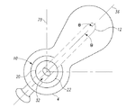
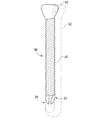
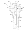
本発明に基づいて、ここで図1を参照すると、長骨4の髄管2内で用いるための髄内釘組立体10が示されている。長骨4は、例えば、大腿骨、脛骨、または上腕骨などの体の任意の長骨とすることができる。
In accordance with the present invention and referring now to FIG. 1, an
本発明に基づいて、図1を参照すると、長骨4の髄管2内でネジ12と共に使用するための、髄内釘組立体10が示されている。髄内釘組立体10は、釘14を含む。釘14は、髄管2内に少なくとも部分的に配置できるように構成されている。釘14は、その釘14を貫通した開口16を画定している。釘14は、その長さ方向軸18を画定している。
In accordance with the present invention and referring to FIG. 1, an
髄内釘組立体10は、ブシュ20も含む。このブシュ20は、釘14の開口16内に少なくとも部分的に配置されている。ブシュ20は、釘14の長さ方向軸18に対して複数の角度位置でネジ12を受容するように構成されている。
The
ブシュ20は、様々な方式または実施態様において複数の角度方向でネジ12を受容するように構成することができる。例えば、釘組立体10は、ブシュ20を釘14の開口16内で移動可能に配置できるように構成することができる。
The
ブシュ20は、任意の様々な適当な構成で釘14内に回転可能に配置することができる。例えば、ブシュ20は、その外面22の周りを回転することができる。ブシュ20は、任意の形状を有することができ、例えば球形にすることができる。例えば、ブシュ20の回転中心線26は、第1の位置にとどまることができる。ブシュ20の中心線26の固定位置は、釘14に形成された凹状クレードル19によって得ることができる。ブシュ20は、ネジ12のシャンク34を受容するための横ブシュ開口(transverse bushing opening)32も含む。横ブシュ開口32は、ブシュ20が球形の場合、任意の向きにすることができる。
The
横開口32は、釘14の長さ方向軸18と角度αをなす横開口中心線36を画定している。この角度αは、ブシュ20を矢印38の方向に回転させて、最適な角度αが得られるように変更すなわち調節することができる。ブシュ20と釘14との間の隙間は、一旦決定された角度αを維持するために最小限にすることができる。
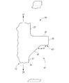
The
ここで図1Aを参照されたい。大腿骨4内に取り付けられた釘組立体10の平面図が示されている。釘組立体10は、ブシュ20が回転可能に取り付けられている釘14を含む。ネジ12が、ブシュ20の横ブシュ開口32内にスライド可能に適合する。ネジ12は、ネジ中心線36を画定している。ブシュ20の形状が球形であるため、ネジ中心線36は、この中心線36から各方向に角度θで矢印24の方向に回転することができる。
Refer now to FIG. 1A. A plan view of the
釘14は、長骨4の髄管2内に適合できるように任意の適当な形状を有することができる。例えば、釘14は、円柱または円形などの形状にすることができる外面40を有することができる。釘14の外面40は、均一にしてもよいし、図1に示されているように、大腿骨4の顆部分6の近傍で大きな直径を有してもよい。外面40は、釘の近位部分42で大きな直径を有し、釘14の遠位部分44で小さな直径を有することができる。釘14は、中実の断面を有してもよいし、図1に示されているように、カニューレ状、すなわち釘14の中心線18に沿って延びる長さ方向の孔46を備えてもよい。釘14は、直線または線形にしてもよいし、長骨4の随管2に一致するように湾曲または曲線状にしてもよい。
The
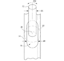
例えば、図2に、釘14の外面40の形状が詳細に示されている。図2に示されているように、釘14は、概ね円形の断面を有する。釘14は、直径DPによって画定されている近位部分42と、近位部分42から延び、直径DDの円形の断面積を有する遠位部分44を含む。
For example, FIG. 2 shows the shape of the
ここで図3および図4を参照されたい。釘14内に配置されて釘組立体10を形成しているブシュ20が詳細に示されている。図3および図4に示されているように、ブシュ20は、釘14に形成された開口16内に適合している。開口16は、ネジ12(図1を参照)が釘14の長さ方向軸18に対して複数の角度位置に配置されるようにブシュ20を受容するべく十分な大きさを有するのが好ましい。
Refer now to FIG. 3 and FIG. A
例えば、図3に示されているように、開口16は、概ね一定の断面を有し、対向した平面の端部48によって画定されている。開口16は、図3に示されているように、平面端部48から延びた対向した半円端部50によっても画定されている。
For example, as shown in FIG. 3, the
ここで図4を参照されたい。開口16の形状により、ネジ12が、弓状の方向にブシュ20の中心線26を中心に、例えば、水平中心線52から近位方向に中心線36までの角度α、および水平中心線56から遠位方向にネジ12の中心線36までの角度βほど回転することができる。
Refer now to FIG. Due to the shape of the
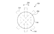
ここで図4Aを参照されたい。釘組立体10は、内/外平面(medial/lateral plane)に示されている。釘組立体10は、球形ブシュ20が旋回可能に取り付けられた釘14を含む。ブシュ20は、ネジ12がスライド可能に適合する貫通開口32を含む。ブシュ20は、ネジ12が、その中心線36から33Aの方向に移動できるように、図4Aに示されているように、釘14に形成された開口16内に適合している。開口16は、ネジ12のシャンクの直径DSよりも広い幅AWを有するため、ネジ12が矢印33Aの方向に回転して、図4Aに示されているように中央内/外側の方向(medial/lateral directions)に移動することができる。
Refer now to FIG. 4A. The
ここで図5を参照されたい。開口16が詳細に示されている。開口16は、例えば、対向した一方の平面端部48から他方の平面端部48まで延びる幅AWによって画定することができる。開口16は、対向した半円端部50を画定している一対の対向した半径Rによっても画定することができる。半径Rは、基点54から延びている。2つの基点54は、距離Lだけ離間している。
Refer now to FIG. The
ここで図5Aを参照されたい。釘組立体10の平面図が示されている。釘組立体10は、第1の部分28で、中実で示されているネジ12が通る開口16を画定している。ネジ12は、第1の位置28から、例えば、第2の位置37および第3の位置39まで矢印33Aの方向に回転することができる。上記したように、ネジ12は、開口16の幅がネジ12の直径DSよりも大きいため、第1の位置28から両方向に角度θだけ、矢印33Aの方向に回転することができる。
Refer now to FIG. 5A. A plan view of the
ここで図5Bを参照されたい。本発明のさらに別の実施形態が釘組立体10Aとして示されている。釘組立体10Aは、図1〜図5の釘組立体10に類似しているが、この釘組立体10Aは、開口16Aに近接して配置された面取り部すなわち平坦部30Aを有する釘14Aを含む。平坦部30Aは、矢印26Aの方向へのさらなる移動を可能にするのに役立つため、ネジ12Aが、釘14Aの中心線18Aに対してより大きな角度で回転する、すなわち弧を描くことができる。
Refer now to FIG. 5B. Yet another embodiment of the present invention is shown as a
ここで図6および図7を参照されたい。ブシュ20が釘に取り付けられていない釘組立体10の釘14の近位部分42が示されている。釘14は、ブシュ20、およびブシュ20の外面22を支持するためのクレードル19を受容するための開口16を含む。釘14は、中実にしてもよいし、図6および図7に示されているようにカニューレ状にしてもよい。釘14は、その長さ方向中心線18に沿って延びる長さ方向の孔46を含む。
Refer now to FIGS. 6 and 7. FIG. The
本発明の複数位置釘組立体は、釘組立体が、例えば大腿骨の頚部を支持できるように、釘に対してブシュの角度位置を選択的に固定して連結するための手段を含むのが好ましい。 The multi-position nail assembly of the present invention includes means for selectively fixing and connecting the angular position of the bushing to the nail so that the nail assembly can support, for example, the neck of the femur. preferable.
ブシュ20は、任意の適当な方式で釘140に対して選択的に固定して連結されることができる。単純にするために、ブシュ20の外面22は、ブシュ20のクレードル19に対して選択的に固定的にまたは回転可能に接触または係合し、ブシュ20を釘14に固定して連結させることができる。
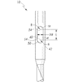
The
例えば、図8に示されているように、固定プラグなどの形態の固定手段54を用いて、ブシュ20を釘14に対して選択的に固定して配置することができる。固定プラグ54は、例えばブシュ20の外面22に選択的に接触させることができる。固定プラグ54は、任意の手段によって選択的にブシュ20に係合することができる。例えば、図8に示されているように、固定プラグ54は、釘14の近位部分42の近位端部に形成されたカウンタボア60に形成された雌ネジ58に螺合する雄ネジ56を含むことができる。固定プラグ54は、ブシュ20の外面22に選択的に接触するステム62を含む。
For example, as shown in FIG. 8, the
例えば、図8に示されているように、ブシュ開口32の中心線36は、適切な角度位置にくるように矢印38の方向に回転させることができる。ブシュ開口32が適切に方向づけられたら、釘14に対するブシュ開口32の角度方向を固定するために、固定プラグ54を回転させて、ステム62を矢印64の方向に前進させ、ステム62がブシュ20の外面22を固定することができる。
For example, as shown in FIG. 8, the
ここで図9を参照されたい。固定プラグ54が詳細に示されている。固定プラグ54は、釘14の雌ネジ58(図7を参照)と協働する雄ネジ56を含む。固定プラグ54は、ブシュ20(図8を参照)に接触するステム62も含む。固定プラグ54は、一般的なネジ回し(不図示)と協働する六角孔(hexagonal drive)66を含むこともできる。固定プラグ54は、長さ方向の中心孔68を含むことができる。
Refer now to FIG. The fixed
ここで図10を参照されたい。釘組立体10の釘14の近位部分42が詳細に示されている。近位部分42は、釘14の長さ方向中心線18に沿って延びる長さ方向の孔46を画定することができる。釘14は、概ね円柱の釘外面40、および釘14の第1の端部29から延びたカウンタボア60を含むことができる。カウンタボア60は、その外径上に形成された雌ネジ58を含むことができる。雌ネジ58は、プラグ54を受容するように構成されている。
Refer now to FIG. The
ここで図11を参照されたい。ブシュ20が詳細に示されている。ブシュ20は、直径DBによって画定されている。ブシュ20は、中心開口32を含むことができる。
Refer now to FIG.
ここで図12を参照されたい。ブシュ20は、概ね球形の形状および円形の断面を有することができ、直径DBによって画定することができる。ブシュ20の中心開口32は、直径DOによって画定することができる。
Refer now to FIG. The
図1〜図3の釘組立体10は、人体に適合性の任意の適当な耐久材料から形成することができる。例えば、釘組立体10は、例えば、金属、プラスチック、または複合材料から形成できる釘14、ブシュ20、および固定プラグ54などの構成要素を含むことができる。金属から形成される場合、釘組立体10の構成要素は、例えば、コバルトクロム合金、ステンレス鋼合金、またはチタン合金から形成することができる。釘組立体10の構成要素は、単純にするために、かつ金属の相互作用を防止するために、全て同じ材料から形成することができる。
The
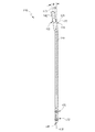
ここで図13を参照されたい。釘組立体10全体が示されている。本発明の釘および釘組立体は、任意の長骨に用いることができ、身体の長骨で任意の様々な市販タイプの髄内釘に用いることができることを理解されたい。
Refer now to FIG. The
図13に示されている釘組立体10は、梨状釘(piri forma nail)の形態である。図13の釘組立体10の梨状釘14は、大腿骨4の顆部分6の梨状部8を貫通するようにデザインされている。大腿骨4の梨状部8は、図13に示されているように、図13の前/後図で見ると、大腿骨4の長さ方向中心線に一致している。したがって、釘組立体10の釘14は、前/後図に示されているように、概ね直線の長さ方向中心線18を有する。
The
釘組立体10は、近位部分42および遠位部分44を含む。近位部分42は、クレードル19において釘14に固定されているブシュ20を含む。釘14は、長さ方向に延びる孔またはカニューレ46を含むことができる。
The
釘14は、釘組立体10を大腿骨4に適切に固定するべく、大腿骨4の遠位部分44にネジを取り付けるための別の横開口をさらに含む。釘14は、1つの遠位開口、または図13に示されているように複数の遠位開口を含むことができる。例えば、釘14は、図13に示されているように、中央から外側の方向に延びることができる第1の遠位開口70、および同様に中央から外側の方向に延びることができる第2の遠位開口72を含む。
The
図14に示されているように、大腿骨の自然の曲線または弓型の性質に対応するために、釘組立体10の釘14は、図14の内外図(medial/lateral view)で見て概ね弓形の形状を有する。釘14の長さ方向中心線18は、図14に示されているように、基点78から延びる半径R1によって画定された方向に延びる。半径R1、および基点78の位置は、人間の大腿骨の形状に似るように選択される。釘14の大きさ、および釘14が対応するようにデザインされた大腿骨の特定の解剖学的縫合線によって、半径R1の基点78の位置およびR1の寸法を相応に変更できることを理解されたい。
As shown in FIG. 14, to accommodate the natural curve or arcuate nature of the femur, the
ここで図15を参照されたい。釘14の遠位部分44における遠位開口70および72が詳細に示されている。第1の開口70および第2の開口72は、任意の適当な形状を有することができることを理解されたい。開口70および72は、釘14の遠位部分44の長さ方向軸18に対して垂直すなわち横向きにすることができる。開口70および72がこのように横向きであるため、横ネジ(不図示)を、開口を通して大腿骨の皮質壁内に固定することができる。
Refer now to FIG. The
開口70および72は、任意の適当な形状を有することができ、図15に示されているように、第1の開口70に示されているような円柱開口を含むことができ、または第2の開口72に示されているような楕円開口を備えることができる。第2の開口72などの楕円開口により、釘14の遠位部分44が骨すなわちネジに対して軸方向に移動することができる。釘組立体10の髄管2内への取付けを容易にするために、釘14は、その端部82から延びたテーパ平坦部80を含むことができる。この平坦部80は、取付け時に髄管2の内壁に接触する。
The
本発明の釘組立体10は、図14および図15に示されているように、2つの遠位開口を含むことができるが、この釘組立体は、別の遠位ネジを受容するため、または釘14の長さ方向軸18に対して様々な角度方向で遠位ネジを受容するために別の開口を含むこともできることを理解されたい。
The
例えば、図16に、本発明の別の実施形態に従った釘組立体10Aが示されている。この釘組立体10Aは、図1〜図3の釘組立体10に類似しており、4つの遠位開口を有する釘14Aを含む。例えば、図16に示されているように、釘組立体10Aは、図15の釘14の第1の開口70に類似した第1の開口70A、および図15の釘14の開口72に類似したスロットの形態である第2の開口72Aを含む。
For example, FIG. 16 illustrates a
釘14Aは、図16に示されているように、第3の開口74Aおよび第4の開口76Aも含むことができる。第3の開口74Aおよび第4の開口76Aは、図16に示されているように、例えば、釘14Aの長さ方向軸18Aに対して横向きすなわち垂直にし、かつ第1の開口70Aおよび第2の開口72Aに対して垂直にすることができる。第3の開口74Aおよび第4の開口76Aは、図16に示されているように概ね円柱状にしてもよいし、図16に示されているように長さ方向軸18Aに対して正確に垂直な方向からやや傾斜するようにしてもよい。
The
ここで図17を参照されたい。本発明の別の実施形態に従った釘インプラント組立体84が示されている。釘インプラント組立体84は、釘組立体10およびネジ12を含む。釘インプラント組立体84は、図17に示されているように、遠位ネジも含むことができる。例えば、遠位ネジは、第1の遠位開口70と協働する第1の遠位ネジ86、および第2の遠位開口72と協働する第2の遠位ネジ88を含むことができる。第1の遠位ネジ86および第2の遠位ネジ88は、例えば、大腿骨すなわち長骨4の皮質骨3に係合するための皮質ネジの形態にすることができる。
Refer now to FIG. A
ここで図17Aを参照されたい。本発明の別の実施形態に従った釘インプラント組立体84Bが示されている。釘インプラント組立体84Bは、釘組立体10Bおよびネジ12Bを含む。釘インプラント組立体84Bは、図17Aに示されているように、釘14Bの遠位部分44Bに固定された遠位ネジブッシュ20Bに形成された遠位ネジ開口70Bを通して遠位ネジ86Bを受容するための遠位ネジブシュ20Bも含むことができる。例えば、遠位ネジ86Bは、例えば、大腿骨すなわち長骨4の皮質骨3に係合するための皮質ネジの形態にすることができる。
Refer now to FIG. 17A. A nail implant assembly 84B according to another embodiment of the present invention is shown. Nail implant assembly 84B includes nail assembly 10B and screw 12B. Nail implant assembly 84B receives distal screw 86B through distal screw opening 70B formed in distal screw bushing 20B secured to distal portion 44B of nail 14B, as shown in FIG. 17A. A distal screw bushing 20B may also be included. For example, the distal screw 86B can be in the form of a cortical screw for engaging the
ここで図18を参照されたい。遠位ネジ86および88が詳細に示されている。遠位ネジ86は、頭部90を含み、この頭部90から細かいピッチの皮質ネジ92が延びている。ネジ86は、頭部90の反対側に自動穿孔/自動タッピング部分94も含む。第2の遠位ネジ88は、第1の遠位ネジ86に類似しており、破線で示されているように長さが変化する。
Refer now to FIG.
図18に破線で示されているように、釘組立体10は、大きな近位皮質ネジ92も含むことができる。このネジ92は、大転子を小転子に取り付けるために用いることができる。
The
ここで図19を参照されたい。図1〜図3の釘組立体10と共に用いるためのネジ12が示されている。このネジ12は、ネジ山96を画定しているシャンク部分を含む。ネジ12は、釘14のブシュ20の開口32内に適合して配置されることができ、かつ釘14に固定して適合するように構成することができる任意のネジとすることができる。例えば、図19に示されているように、ネジ12は、シャンク34から延びた頭部すなわちリップ90を含むことができる。
Reference is now made to FIG. A
リップ90は、ネジ12がブシュ20の開口32を通って移動するのを防止するようにデザインすることができる。リップ90は、ネジ12が開口32から横に移動するのを防止できる任意の適当な大きさおよび形状を有することができる。例えば、リップ90は、開口32の直径ODよりも大きいリップ直径LDを有することができる。
The
ここで図19を参照されたい。ネジ12は、例えば、ネジ12に形成されたスロット21の形態である回転機能部を含むすなわち画定することができる。スロット21は、任意の適当な大きさを有することができる。スロット21は、ネジ12の回転を容易にするために用いることができ、ネジ12の長さ方向中心線23の周りに配置することができる。スロット21は、スロット幅SWおよびスロット深さSDを有することができる。スロット21は、このスロット21によって生じる応力集中(stress risers)を軽減するべく、スロット21に位置する半径範囲(radius)を含むことができる。スロット幅SDおよびスロット長さSLは、ネジ12を長骨4内に植え込むために、ネジ12が、例えばネジ回し(不図示)と協働するのに十分であるようにデザインされている。スロット21の代わりに、内部または外部に六角形または四角形の機能部(不図示)を用いることができる。
Reference is now made to FIG. The
図19に示されているように、ネジ12は、カニューレ状にすることができ、ネジ12の長さ方向中心線23に沿って延びる長さ方向の開口25を含むことができる。長さ方向の孔25は、例えば、ガイドワイヤ(不図示)を受容して、釘組立体10の開口32内の所定の位置にネジ12を案内し、ネジ12を長骨4内に適切に配置するために用いることができる。
As shown in FIG. 19, the
ネジ12は、例えば、ネジ12のスロット21に近接した長さ方向の開口25に形成された小さなカウンタボア(不図示)に形成された、例えば雌ネジの形態の、不図示の取外し機能部を含むこともできる。ネジ12は、その端部から延びる大きなカウンタボア(不図示)をも含むことができ、ネジ12は、小さなカウンタボアおよび長さ方向の開口25と同心にすることができる。
For example, the
図19に示されているように、ネジ12は、そのシャンク34に形成された複数のネジ山96を備えることもできる。ネジ山96は、図19に示されているように、参照して本明細書に組み入れる米国特許出願第60/627,266号に詳細に開示されているような均一でない断面を有することができる。
As shown in FIG. 19, the
再び図19を参照されたい。ネジ12のシャンク34は、ネジが内部に形成された第1の部分27を含む。第1の部分27は、ネジ12の長さ方向軸23に沿ってネジ12の第1の端部29から第2の端部31まで延びることができることを理解されたい。図19に示されているように、シャンク34が第2の部分33を含むことができることも理解されたい。シャンク34の第2の部分33は、平滑な表面を画定することができる。図19に示されているように、シャンク34は、概ね円柱状であって、例えば直径DSによって画定することができる。
Please refer to FIG. 19 again. The
ネジ12は、図19に示されているように、概ね円柱状であって、直径DSおよび全長Lによって画定されている。ネジ12のシャンク34は、ネジ山96を含む第1の部分27および平滑な表面を有する第2の部分33を含む。直径DSの全長Lは、ネジが設けられた長さTLと平滑すなわちネジが設けられていない長さULに分かれている。ネジが設けられた長さTLは、第1の部分27を画定し、平滑な長さULは、第2の部分33を画定している。ネジが設けられた長さTLは、例えば、シャンク34の全長Lの、例えば20%〜40%の部分とすることができる。平滑な長さULは、ネジ12の第2の部分33が、髄内釘14のブシュ20の傾斜開口32内に配置され(図1〜図3参照)、大腿骨4の骨折部をスライド式に圧縮できるように十分な長さであるのが好ましいことを理解されたい。
The
ネジ山96は、図19に示されているように、ネジ12のシャンク34の周りを螺旋状に進むことができる。ネジ山96は、長さ方向軸23に沿って近接するネジ山間の間隔を画定するピッチPによって画定することができる。ネジ山96は、右または左螺旋構造のいずれかで、長さ方向軸23の周りを螺旋状に進むことができる。ネジ山96は、図19に示されているように、単一リード型(single lead type)とすることができるが、別法として、二重リード構造(double lead configuration)または三重リード構造(triple lead configuration)とすることができる。
The
ここで図19Aを参照されたい。完全にネジ山が設けられた皮質ネジ12Aが示されている。完全にネジが設けられた皮質ネジ12Aは、図1〜図5の釘組立体10に類似した釘組立体10Aに用いることができる。ネジ12Aは、図19Aに示されているように、完全にネジが設けられたシャンク34Aを含む。すなわち、ネジ12Aは、頭部90Aからネジ12Aの第1の端部29Aまでネジ12Aのシャンク34Aの外面の周りに延在するネジ山96Aを含むシャンク34Aを含む。
Refer now to FIG. 19A.
ここで図20を参照されたい。ネジ山96は、任意の適当な形状すなわちネジ形を有することができる。例えば、図20に示されているように、ネジ山96は、ボックスとテーパを組み合わせた構造を有することができる。例えば、図20に示されているように、ネジ山96は、任意の適当な形状または輪郭を有することができる。例えば、図20に示されているように、この輪郭は、山の頂(crest)35、および反対側の谷底(root)37を含むことができる。後面39が、ネジ12の第2の端部31に近接した谷底37と山の頂35との間に位置し、前縁41が、ネジ12の第1の端部29に近接した谷底37と山の頂35との間に位置している。
Refer now to FIG. The
図20に示されているように、前縁41および後縁39は、矢印31の方向に取り外す力よりも矢印29の方向に取り付ける力が小さくなるように構成することができる。このように取付けを容易にし、かつ取外しを困難にすることは、図20に示されているように、谷底37および山の頂35に対して直角をなす、すなわち垂直な構造の後縁39を設け、かつ垂直面43と谷底37との間の傾斜面45および垂直面43を備えた前縁41を設けることで達成することができる。
As shown in FIG. 20, the
ネジ12のネジ山96は、図20に示されているように、垂直面43および傾斜部分45を含む前縁41を含む。傾斜部分45により、ネジ12を長骨すなわち大腿骨4内に取り付ける際に必要な力が軽減される。垂直面43と傾斜部分45は、これらの間に角度ααを画定することができる。応力を最小限にするべく、山の頂35、谷底37、後面39、および前縁41は、これらの間に弓形部分を含むことができる。
The
ここで図20A〜図20Fを参照されたい。本発明の釘のネジのネジ山についての代替の輪郭構造が示されている。図20Aを参照すると、弓状の谷底および山の頂を有する輪郭47Aが示されている。例えば、図20Aに示されているように、ネジ12Aの輪郭47Aは、傾斜後面39Aが延びる弓状の山の頂35Aを含む。前縁41Aは、同様に弓状の山の頂35Aから延びている。輪郭47Aは、後面39Aと前面41Aを連結する弓状の谷底37Aも含む。
Refer now to FIGS. 20A-20F. An alternative profile structure for the thread of the nail screw of the present invention is shown. Referring to FIG. 20A, a
ここで図20Bを参照されたい。本発明のネジのネジ山のさらに別の輪郭が、概ねV型のネジ山96Bを含む輪郭47Bを有するネジ山96Bを含むネジ12Bとして示されている。輪郭47Bは、後面39Bおよび前面41Bを含む。谷底37Bおよび山の頂35Bは、図20Bに示されているように最小である。
Refer now to FIG. 20B. Yet another profile of the thread of the screw of the present invention is shown as a
ここで図20Cを参照されたい。本発明に従ったネジのネジ山のさらに別の輪郭が示されている。例えば、図20Cに示されているように、ネジ12Cは、ブロック型すなわち矩形の輪郭47Cを有するネジ山96Cを含む。輪郭47Cは、後面39Cおよび離間して平行な前面41Cを含む。後面39Cおよび前面41Cは、谷底37Cおよび山の頂35Cに対して直角をなす、すなわち垂直である。
Refer now to FIG. 20C. A further profile of the thread of the screw according to the invention is shown. For example, as shown in FIG. 20C, the
ここで図20Dを参照されたい。本発明に従ったネジのネジ山の輪郭のさらに別の実施形態が示されている。ネジ12Dのネジ山96Dの輪郭47Dは、標準的なネジ山の形状である概ね切頭V型の形状を有する。輪郭47Dは、平坦な山の頂35D、向かい合った傾斜後面39Dおよび前面41Dを含む。谷底37Dは、後面39Dおよび前面41Dから延びている。
Refer now to FIG. 20D. A further embodiment of the thread profile of the screw according to the invention is shown. The contour 47D of the thread 96D of the screw 12D has a generally truncated V shape that is a standard thread shape. The contour 47D includes a flat mountain crest 35D, opposed inclined
ここで図20Eを参照されたい。本発明のネジのネジ山のさらに別の輪郭が輪郭47Eとして示されている。ネジ12Eは、輪郭47Eを有するネジ山96Eを含む。輪郭47Eは、山の頂35Eおよび離間して平行な谷底37Eに対して垂直である、後面41Eを含む。輪郭47Eは、谷底37Eと山の頂35Eとの間に所与の角度で配置された後面39Eも含む。
Refer now to FIG. 20E. Yet another contour of the thread of the present invention is shown as
本発明に従って、図20Fを参照すると、本発明のネジの輪郭のさらに別の形が示されている。図20Fのネジ12Fは、輪郭47Fを画定しているネジ山96Fを含む。輪郭47Fは、離間して平行な山の頂35Fおよび谷底37Fを含む。輪郭47Fは、谷底37Fおよび山の頂35Fに垂直な後面39Fを含む。輪郭47Fは、谷底37Fと山の頂35Fとの間に所与の角度で配置された表面41Fも含む。
In accordance with the present invention, and with reference to FIG. 20F, yet another form of the screw profile of the present invention is shown. The
ここで図21を参照されたい。釘組立体10の釘14の近位部分42が詳細に示されている。釘組立体10は、釘組立体10内に配置されて釘インプラント組立体84を形成しているネジ12と共に示されている。図21に示されているように、ネジ12は、ブシュ20に形成されたブシュ開口32内にスライド可能に適合するシャンク34を含む。
Refer now to FIG. The
図21に示されているブシュ20は、例えば、釘14に形成された横開口32と協働するクレードル19および固定ピン54によって、釘14に回転可能に固定されている。図21に示されているように、ネジ12は、ネジ山96を含む第1の部分27、および図21では平滑な外面を有する第2の部分33を含む。ブシュ20の開口32内に適合するネジ12のシャンク34の部分は、平滑であって、骨折、特に大腿骨頚部の骨折の治癒を助けるべくスライド式の圧縮が可能である。
The
しかしながら、ネジ山96が、ネジ12のシャンク34全体に亘って延びてもよく、ネジ山96がブシュ20の開口32内に適合しうることを理解されたい。このような構造は、大腿骨頚部の骨折において、スライド式の圧縮に寄与せず、同程度の治癒が実現できない場合がある。
However, it should be understood that the
ブシュ20が矢印38の方向に回転できるため、ネジ12の長さ方向中心線36が、同様に矢印38の方向に回転することができる。したがって、本発明の釘組立体10を用いることにより、ネジ12の長さ方向中心線36が、実線で示されている第1の位置27から、破線で示されている第2の位置39に移動することができる。ブシュ20が回転できるため、ネジ12の中心線36が破線で示されている第3の位置41に移動することもできる。
Since the
ネジ12の中心線36は、実線で示されている第1の位置27と破線で示されている第3の位置41との間の任意の位置に配置できることを理解されたい。回転可能なブシュ20を有する釘組立体10を提供することにより、釘14の長さ方向中心線18に対するネジの様々な角度方向が可能となる。
It should be understood that the
ブシュ20が適切な位置に回転し、ネジ12の長さ方向中心線36が所望の向きにきたら、固定プラグ54を回転させて、固定プレート54を矢印64の方向に前進させ、固定プレート54のステム部分62をブシュ20の外面22に係合させることができる。したがって、ステム部分62が、ブシュ20を固定角度方向に固定する。
When the
図21に示されているように、ネジ12が、実線で示されている第1の位置37にある場合、ネジ12の頭部90が、大腿骨4の皮質骨3に支持され、ネジ12のシャンク34の第2の部分33が、ブシュ20の開口32を貫通している。ネジ12の第1の部分27に形成されたネジ山96が、大腿骨4の頚部5の海綿骨質に係合し、大腿骨4の骨頭7に向かって延びている。
As shown in FIG. 21, when the
ここで図21Aを参照されたい。釘組立体10が斜視図で示されている。釘組立体10は、細い遠位部分44および拡大近位部分42を有する釘14を含む。釘14は、ブシュ20が旋回可能に固定される孔すなわち開口16を画定している。ブシュ20は、ネジ12をスライド可能に受容するための貫通開口32を含む。図21Aに示されているように、ネジ12は、例えば、実線で示されている第1の位置37に配置することができる。ネジ12はまた、破線で示されている第2の位置39でも示されている。ネジ12は、破線で示されている第3の位置41でもさらに示されている。ネジ12の向きは、3つ全ての平面で変更できることを理解されたい。
Refer now to FIG. 21A. The
ここで図21Bを参照されたい。釘14の上方から見たネジ12が示されている。釘組立体10は、実線で示されている第1の位置37に配置できるネジ12を含む。ネジ12は、破線で示されている第2の位置39に配置することもできる。ネジ12は、例えば、破線で示されている第3の位置41に配置することもできる。
Refer now to FIG. 21B. The
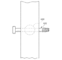
ここで図22を参照されたい。釘組立体10が、釘インプラント組立体84を構成しているネジ12と共に示されている。釘インプラント組立体84は、小転子骨折部に対して大転子を固定するために用いられるように構成されている。釘インプラント組立体84は、ブシュ20と共に釘組立体10を構成する釘14を含む。
Refer now to FIG.
ブシュ20は、ブシュ中心線36が大転子9から小転子11に延びるように向いている。釘組立体10のブシュ20を、ブシュ20の横中心線36が大転子9から小転子11まで一列になるように位置に回転させ、固定プラグ54を用いて、ブシュ20を釘14に固定する。
The
ネジ12の頭部90は、大転子9で皮質骨3に支持されている。ネジ12のシャンク34は、ブシュ20内を通り、ネジ12のネジ山96は、大腿骨4内に延び、図22Aに示されているように、大腿骨4の小転子11に近接した皮質骨3内に延びることができる。
The
ここで図23を参照されたい。骨折部13が大腿骨4の頚部5に延在する大腿骨4が示されている。骨折部13は、頚部5を横断するように延在している。図23に示されているように、釘組立体10のブシュ20は、ネジ12が釘組立体10のブシュ20内に配置された時に、このネジ12が骨折部13に交差して、ネジ12が骨頭7を大腿骨4の残りの部分に固定する働きをするように、ブシュ20の横開口32の中心線36が配置されるよう、矢印64の方向に回転することができる。図23に示されているように、ブシュ20の開口32の長さ方向軸36は、骨頭7を大腿骨4に適切に固定するように整合している。固定プラグ54を用いて、ブシュ20を釘14に固定することができる。
Reference is now made to FIG. The
ここで図24を参照されたい。本発明の釘インプラント組立体84が、図示されているように、長さ方向の骨折部15が大腿骨4の本体から頚部5を経て骨頭7内に至っている大腿骨4に用いられている。釘組立体10が、骨頭7を大腿骨4に適切に固定するべく、ネジ12が骨折部15を横断するように延びるよう方向付けされていることを理解されたい。
Refer now to FIG. A
図24に示されているようにネジ12は、適切な角度で骨折部15に交差して、骨頭7を大腿骨4に適切に固定することができるように、頚部5および骨頭7の物理的中心線とは異なる方向に向けることができる。ブシュ20は、その横軸36が適切な向きにある状態で方向付けられたら、固定プラグ54をブシュ20に固定して固定プラグ54を釘14に固定する。
As shown in FIG. 24, the
ここで図25を参照されたい。大腿骨4の遠位顆部分17から大腿骨4の髄管2内に挿入された本発明の釘インプラント組立体84が示されている。釘インプラント組立体84は、釘組立体10を形成する釘14およびブシュ20を含む。釘組立体10は、大腿骨4の遠位顆部分17を通って髄管2内に挿入されている。ネジ12は、大腿骨4の遠位顆部分17の皮質骨3を通して挿入され、ブシュ20のブシュ開口32を経て大腿骨4内に至っている。大腿骨4の遠位顆部分17内に植え込まれたこのような釘インプラント組立体84は、逆方向釘と呼ばれる場合が多い。
Refer now to FIG. Shown is the
図1の釘インプラント組立体84は、手術中に(interoperatively)固定された頚部角度αを有することができるが、この頚部角度αは、例えば、釘組立体10を患者に植え込む前に手術室の台で予め設定することができることを理解されたい。
The
例えば、図26に、大腿骨4の前後図のX線写真45が示されている。X線写真45に示されているように、大腿骨4の頚部5および骨頭7が、頚部角度αとして定義された角度を大腿骨4となしている。頚部角度αは、X線写真45から決定することができる。
For example, FIG. 26 shows an
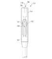
ここで図27を参照されたい。ブシュ20を釘14内に位置決めするための装置47が示されている。装置47は、釘組立体10と共に釘キット49を形成する。
Refer now to FIG. A
装置47は、例えば、図1〜図4の釘組立体10などの髄内釘と共に使用するための固定具の形態にすることができる。釘組立体10は、例えば、図1〜図4に示されている釘14などの釘本体を含む。釘組立体10は、釘14に対して方向付けることができる図1のネジ12などのネジを受容するためのブシュ20などのネジ機能部も含む。固定具47は、釘14に対してブシュ20を方向付けるように構成されている。
The
固定具47は、釘14と協働するための第1の部分51を含む。固定具47は、第2の部分53も含む。第2の部分53は、釘14に対するブシュ20の複数の位置の1つに一致することができる。固定具47は、ブシュ20に形成された開口32内にスライド可能に適合する固定ピンの形態である、例えば図27に示されているような機能部55と協働するネジ機能部も含む。固定ピンは、例えば、ネジ12の形態としてもよいし、別の構成要素としてもよい。ネジ機能部と協働する機能部55は、ブシュ20と協働して第2の部分53と共に用いられる。
第2の部分53は、図27に示されているように、第1の部分51に対して固定して配置することができる。例えば、図27に示されているように、第2の部分53は、第1の部分51と一体にすることができる。別法では、第2の部分53は、第1の部分に対して選択可能に配置可能とすることができる。例えば、第2の部分53は、第1の部分51に対して旋回可能に配置することができる。この旋回位置は、ブシュ20の中心に一致させることができる。
The
釘14は、釘14を第1の部分51に寄りかからせる単純な重力で第1の部分51に配置することができる。例えば、図27に示されているように、第1の部分51は、釘14の外面を支持するV型をなす一対の平面の形態である。第1の部分51を形成する平面は、重力により釘14が第1の部分51に保持されるように配置されている。釘14は、この釘14を第1の部分51に対して配置して保持できるコレット、クランプ、付勢部材、または任意の他の装置によって固定することができることを理解されたい。
The
固定具47は、その第1の部分51に釘14を固定するための手段も含むことができる。この固定手段は、例えば、固定具47の第1の部分51に取り付けることができるクランプ57の形態にすることができる。
ネジ機能部と協働する機能部55は、ブシュ20と協働してブシュ20の向きを表示できる任意の機能部とすることができる。ネジ機能部と協働する機能部55は、ブシュ20に形成された開口32にスライド可能に適合することができる。ネジ機能部と協働する機能部55は、実際は、単純に、患者に植え込まれるネジ12とすることができる。単純にするため、および植え込まれるネジ12の汚染を防止するために、ネジ機能部と協働する機能部55は、例えば、第2の部分53と協働する円柱ピンなどの別個の構成要素とすることができる。ネジ機能部と協働する機能部55は、第2の部分53と協働するチップすなわちポインタ59を含むことができることを理解されたい。
The
固定具47は、ネジ機能部と協働する機能部55を固定具47の第2の部分53に固定するための手段も含むことができる。例えば、ネジ機能部と協働する機能部55は、第2の部分53に取り付けられて第2の部分53にピン55を固定するクランプ61の形態である、ピン55を固定するための手段を備えたピンとすることができる。
The
固定具47は、釘14に対するネジ機能部20の位置を測定するための計器63も含むことができる。例えば、計器63は、固定具47の第2の部分に設けられた分度器63すなわち一連の刻み線の形態にすることができる。分度器63は、概ね平面であって、ピン55のポインタ59をオーバーレイすることができる。
The
固定具47は、釘14に対する横開口32の角度関係を事前設定するための事前設定機能部65も含むことができる。例えば、事前設定機能部65は、ピン55と協働して横開口32の角度関係を特定の角度関係αに事前設定するばね付勢戻り止めの形態にすることができる。
The
固定具47は、第1の部分51および/またはネジ機能部と協働する機能部55が、直径、長さ、および形状が異なる複数の髄内釘に対応するように構成されるよう構成できることを理解されたい。例えば、図27に示されているように、第1の部分51は、V型を形成する一対の平面の形態にして、その結果、釘14が相反する方向に延在できるようにし、様々な長さの釘14を固定具47と共に使用可能にすることができる。さらに、V型を形成する平面を備えた第1の部分51を用いることにより、様々な直径の釘14が可能となる。
The
ここで図27Aを参照されたい。釘キット49の装置47の第2の分度器63Aが示している。第2の分度器63Aは、図27の第1の分度器63にやや類似している。第2の分度器63Aを用いて、装置47の第1の部分51のウエッジすなわちV型部分内の釘14を回転可能に方向付けることができる。第2の分度器63Aは、第2の協働機能部55Aから延びることができるポインタ59Aと協働する表示(indicia)67Aを含む。第2の協働機能部55Aは、釘14に形成された角度方向機能部99と協働する。角度方向機能部99は、線形に整合している一組のノッチの形態にすることができる。
Refer now to FIG. 27A. The
釘14が矢印38Aの方向に回転して、ポインタ59Aに、分度器63Aの表示67Aの異なる部分を通過させることができる。
The
ポインタ59Aは、例えば、中心線36Aから両方向に所与の距離すなわちθの距離を移動することができる。
The
ここで図28を参照されたい。分度器63の上に位置しているポインタ59が示されている。分度器63は、目盛69の形態にできる表示67および対応する数字または文字71を含むことができる。数字および/または文字71は、釘14に対するブシュ開口32の特定の角度すなわち特定の所望の角度位置αに一致することができる。
Reference is now made to FIG. A
対応する機能部すなわちピン55は、図28に示されているように、ポインタ59が分度器63の表示67に示されている適切な位置に整合するまで回転すなわち一直線にすることができる。ポインタ59が、分度器63の適切な表示67の上にきたら、釘組立体10が、体内に移植するのに適切に方向付けられるように、固定ピン54を回転させて固定ピン54をブシュ20に固定する。次に、ピン55をブシュ開口32から取り外し、釘組立体10は、植え込む準備ができる。
The corresponding feature or pin 55 can be rotated or aligned until the
ここで図28Aを参照されたい。釘キット49の装置47が、分度器63Aと共に詳細に示されている。分度器63Aは、ポインタ59Aが延びている協働機能部55Aを含む。ポインタ59Aは、分度器63Aに形成された表示67Aに整合している。文字または数字の形態の符号71Aを、ポインタ59Aの位置を容易に表すことができるように表示67Aに関連させることができる。
Refer now to FIG. 28A. The
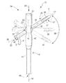
ここで図29を参照されたい。本発明の別の実施形態が釘組立体110として示されている。釘組立体110は、転子釘組立体の形態である。釘組立体110は、図1〜図4の釘組立体10に類似しているが、この釘組立体110の転子釘114が、その遠位部分144に整合していない、または傾斜した近位部分142を含むという点で、転子釘114は、図1〜図4の釘組立体10の釘14とは異なっている。
Refer now to FIG. Another embodiment of the present invention is shown as a
近位部分142は、遠位部分144の中心線118と角度θをなす近位部分中心線173を画定している。この角度θは、転子釘組立体110を、大腿骨4の大転子9を介して挿入しやすいように選択される。
図29に示されているように、転子釘組立体110は、転子釘114を含む。この転子釘114は、その近位部分142に開口116を画定している。開口116は、ネジ112を受容するための横開口132を画定するブシュ120を受容する。ブシュ120は、例えば、クレードル119と固定ピン116との間に収容されるなどして釘114に回転可能に固定されている。釘114は、長さ方向中心線118と整合した長さ方向の孔146を画定している。釘114は、図29に示されているように、第1の遠位開口170および第2の遠位開口172を含むことができる。
As shown in FIG. 29, the
ここで図30を参照されたい。釘114の遠位部分144は、直線すなわち線形にしてもよいし、図30に示されているように、大腿骨の髄管の弧すなわち曲線に一致するように弧状すなわち曲線状にしてもよい。図30に示されているように、釘114の遠位部分144は、曲線状であるか、または基点178から延びる半径R2によって画定された弧を形成している。
Reference is now made to FIG. The
本発明の釘は、股関節頚部の骨折に用いる髄内釘に利用できるが、本発明の釘は、長骨の骨折においてほかの場所で用いることができることを理解されたい。 While the nail of the present invention can be used for intramedullary nails used for hip neck fractures, it should be understood that the nail of the present invention can be used elsewhere in long bone fractures.
例えば、図31および図32に示されているように、本発明の釘は、図31および図32に示されている逆方向大腿骨釘インプラント組立体284に用いることができる。
For example, as shown in FIGS. 31 and 32, the nail of the present invention can be used in the reverse femoral
ここで図31を参照されたい。釘インプラント組立体284は、ネジ212を複数の角度位置に配置できる釘組立体210を含む。釘インプラント組立体284は、図31に示されているように、釘組立体210の釘214に形成された第1の近位開口270内にスライド可能に適合する第1の近位ネジ286も含む。釘インプラント組立体284は、釘214に形成された第2の近位開口272内にスライド可能に適合する第2の近位ネジ288も含む。
Refer now to FIG. The
図31に示されているように、釘インプラント組立体284は、釘214にスライド可能に適合する第2の遠位ネジ275も含むことができる。釘インプラント組立体284は、ブシュ220が適合する遠位開口216を含む釘214を含む。ブシュ220は、ネジ212がスライド可能に適合する開口232を含む。ブシュ220の開口232は、必要に応じて、釘214の軸218に対して調節できる軸236を含む。
As shown in FIG. 31, the
ここで図32を参照されたい。ブシュ220は、例えば、釘214に螺合する固定プラグ254によって選択可能に固定することができる。ブシュ220は、例えば、釘214に形成されたクレードル219と固定プラグ254との間で回転することができる。
Refer now to FIG. The
本発明の釘は、大腿骨に使用するのに特に適しているが、本発明の釘は、例えば脛骨などの他の長骨にも用いることができることを理解されたい。 While the nail of the present invention is particularly suitable for use on the femur, it should be understood that the nail of the present invention can also be used on other long bones, such as the tibia.
例えば、図33および図34に示されているように、本発明の釘は、釘組立体310の形態にすることができる。図33および図34に示されている釘組立体310は、脛骨に用いる釘の形態にすることができる。このようなある釘は、図33および図34に示されているように、釘融合(nail fusion)に用いることができる。釘組立体310は、図33に示されているように、体の踵骨79内に挿入し、さらに脛骨77の髄管94を通して挿入することができる。
For example, as shown in FIGS. 33 and 34, the nail of the present invention can be in the form of a
釘組立体310は、釘314を含むことができる。釘314は、ブシュ320が適合する横開口316を含む。ブシュ320は、例えば、釘314に形成されたクレードル319と固定プラグ354との間に拘束されるなどして釘314に回転可能に適合する。釘組立体310は、近位部分342、および開口316が設けられている遠位部分344を含む。遠位部分344は、ブシュ320に形成された開口332が適切に配置されると、ブシュ320を適所に選択的に固定する固定プラグ354も含むことができる。釘314は、その中心線318に沿って延びる長さ方向の孔346も含むことができる。
The
本発明の釘は、足から挿入する脛骨釘に用いることができるが、本発明の釘は、図35に示されているように、例えば、脛骨77の近位部分を通して挿入される釘組立体410の形態にできることを理解されたい。
The nail of the present invention can be used for a tibial nail inserted from a foot, but the nail of the present invention can be inserted, for example, through a proximal portion of a
釘組立体410は、ブシュ420が適合する横ブシュ開口432を画定する釘414を含む。ブシュ420は、釘414に形成されたクレードル419と固定ピン454との間に拘束されて、ブシュ420に回転可能に適合しうる。ブシュ420は、釘組立体410を形成するためにネジ412を受容するためのブシュ開口432を含むことができる。釘414は、ブシュ420が配置される近位部分442、および遠位開口470および472を備えることができる遠位部分444も含むことができる。釘414は、カニューレ状にする、すなわち釘414の中心線418に沿って形成された長さ方向の孔446を含むことができる。
ここで図36を参照されたい。本発明の釘組立体は、足の長骨以外の他の骨にも用いることができることを理解されたい。例えば、本発明の釘は、例えば、上腕骨79に用いることができる。
Refer now to FIG. It should be understood that the nail assembly of the present invention can be used on other bones besides the long bones of the foot. For example, the nail of the present invention can be used for the
図36に示されている釘組立体510は、長骨79の髄管181に近位側に挿入される釘514を含むことができる。釘514は、例えば、釘514に形成されたクレードル519と釘514に固定された固定プラグ554との間に拘束されることによってブシュ520が回転可能に適合する開口516を含むことができる。釘514およびブシュ520が固定プラグ554と一体になって、釘組立体510を構成する。
The
釘514は、図36に示されているように、長さ方向中心線518を画定している遠位部分544を含むことができる。釘514は、遠位部分544から延びる近位部分542も含むことができる。近位部分542は、開口516を含む。
The
ブシュ520は、ネジ512がスライド可能に通り抜けるブシュネジ開口532を含む。ネジ512と釘組立体510が一体になって、釘インプラント組立体584を構成する。釘514は、その長さ方向中心線518と同心に延びる長さ方向の孔546を含むことができる。
The
ここで図37を参照されたい。本発明のさらに別の実施形態が釘組立体610として示されている。釘組立体610は、釘614を含む。釘614は、プラグ756を受容するためのポケット661を画定している近位部分642を含む。釘614は、ブシュ620を部分的に受容するためのクレードル619を画定している。クレードル619は、凹状であって、図37に示されているように、概ね半球形である。プラグ756は、同様に概ね半球形であってブシュ620の外面622と結合する凹面635を含む。プラグ756は、任意の適当な方法で釘614に固定される。例えば、図37に示されているように、プラグ756は、ネジ664を受容する横開口666を含む。ネジ664は、釘610に形成された、ネジが設けられたポケット668に螺合する。
Refer now to FIG. Yet another embodiment of the present invention is shown as a
ここで図38を参照されたい。釘組立体610が、釘614およびプラグ756と共に示されている。図38に示されているように、釘組立体610は、プラグ756によって収容されたブシュ620に形成された開口632内にスライド可能に適合するネジ612も含むことができる。
Refer now to FIG.
ここで図39を参照されたい。プラグ756が詳細に示されている。プラグ756は、ネジ664を受容するための横開口666、およびブシュ620を受容するための凹面635を含む。
Reference is now made to FIG.
ここで図40を参照されたい。ネジ664が詳細に示されている。ネジ664は、頭部690、およびネジが設けられたシャンク634を含むことができる。
Reference is now made to FIG.
図1〜図40に示されている本発明は、髄内釘内で回転するブシュを提供するが、本発明は、平行移動および回転するブシュを備えた釘の形態にもすることができることを理解されたい。ブシュ720は、釘714の平坦部または凹部(不図示)と協働してブシュ720の回転を防止する平坦部または突出部(不図示)を有することができることを理解されたい。このような場合、ブシュは、1つの軸を中心に回転するだけである。
Although the invention shown in FIGS. 1-40 provides a bushing that rotates within an intramedullary nail, the invention can also be in the form of a nail with a translational and rotating bushing. I want you to understand. It should be understood that the
例えば、図41〜図44に示されているように、本発明の別の実施形態が釘組立体710として示されている。釘組立体710は、ブシュ720と協働する釘714を含む。ブシュ720は、回転し、かつ釘714の長さ方向軸718に沿って平行移動する。
For example, as shown in FIGS. 41-44, another embodiment of the present invention is shown as a
ブシュ720は、任意の適当な方式で長さ方向軸718に沿って平行移動および回転することができる。例えば、図42に示されているように、ブシュ720は、釘714に形成された円柱の開口746に沿って平行移動および回転することができる。ブシュ720は、釘714に形成された弓状部分781と結合する外面722を含む。弓状部分781は、円柱開口746の一部とすることができる。
The
再び図41を参照されたい。ブシュ720は、任意の適当な方式で釘714内に固定可能に配置することができる。例えば、図43に示されているように、釘組立体710は、ブシュ720の一端を配置するために釘714に螺合する遠位固定プラグ756も含むことができる。遠位固定プラグ756と向かい合った、近位固定プラグ787は、釘714に螺合することができ、ブシュ720に接して配置可能で、ブシュ720を遠位固定プラグ756と近位固定プラグ787との間に固定することができる。
Please refer to FIG. 41 again. The
図41に示されているように、ネジを受容するために、開口732がブシュ720に形成されている。釘組立体710が、大腿骨頚部のネジと共に用いる釘として用いられる場合、開口732は、ネジが大腿骨の頚部内および骨頭内に進入するように適切な角度に方向付けることができる。ネジが他の方法で用いられる場合、開口732は、例えば、長さ方向軸718に対して直角をなす、すなわち垂直にすることができる。
As shown in FIG. 41, an
ここで図43を参照されたい。遠位プラグ756が詳細に示されている。遠位プラグ756は、釘714に螺合する雄ネジ798、およびブシュ720(図41および図42を参照)の外面722を受容するための凹面735を含む。
Refer now to FIG. The
ここで図44を参照されたい。近位ブシュプラグ787が詳細に示されている。近位ブシュプラグ787は、概ね円柱状であり、釘714に係合する雄ネジ797を含む。ブシュプラグ787は、ブシュ720の外面722と協働するクレードル719も含むことができる。
Refer now to FIG. The
本発明は、複数の角度で配置できる1つのネジを有する釘に用いることができるが、本発明は、様々な角度で配置するために2つのネジを有する釘にも用いることができることを理解されたい。 While the present invention can be used with nails having a single screw that can be placed at multiple angles, it is understood that the present invention can also be used with nails having two screws for placement at various angles. I want.
例えば、本発明に従って、図45を参照すると、釘組立体810が示されている。釘組立体810は、第1の開口816および離間した第2の釘開口889を有する釘814を含む。第1のブシュ820が、第1の釘開口816内に回転可能に配置されている。第1のブシュ開口832が、第1のブシュ820に形成され、第1のネジ(不図示)を受容するように構成されている。第2の釘開口889は、第2のブシュ891を受容するように構成されている。第2のブシュ891は、釘814内に回転可能に配置され、第2のブシュ891に形成された第2のブシュ開口893を有する。
For example, referring to FIG. 45 in accordance with the present invention, a
第2のブシュ開口893は、第2のネジを受容するように構成されており、第1のブシュ開口832は、第1のネジを受容するように構成されていることを理解されたい。第1のネジおよび第2のネジは、同様の方向に向けることができることを理解されたい。例えば、第1のネジおよび第2のネジの両方を、大腿骨の頚部および骨頭内に配置することができる。第2のネジは、回転防止ネジの形態にして、大腿骨頚部が骨折した場合に、大腿骨の骨頭および/または頚部を骨幹に適切に固定することができる。
It should be understood that the second bushing opening 893 is configured to receive a second screw and the
ここで図46を参照されたい。本発明に従った釘インプラント組立体884が示されている。釘インプラント組立体884は、釘814、第1のブシュ820、および第2のブシュ891を含む釘組立体810を含む。第1のネジ812が、第1のブシュ820内にスライド可能に適合し、第2のネジ895が、第2のブシュ891をスライド可能に通り抜ける。第1のネジ812および第2のネジ895は、大腿骨4の頚部5および骨頭7内に延びる。
Refer now to FIG. A
ここで図47を参照されたい。図46の釘インプラント組立体884の別の使用が詳細に示されている。釘インプラント組立体884は、釘組立体810、第1のネジ812、および第2のネジ895を含む。釘814は、大腿骨4の髄管内に適合し、第1のネジ812は、釘814の開口816内に適合するブシュ820に形成された開口832をスライド可能に通り抜ける。図47に示されているネジ812は、大腿骨4の頚部および骨頭の海綿骨質内に延びることができる。
Refer now to FIG. Another use of the
図47に示されているように、釘インプラント組立体884は、この場合は皮質ネジ895である、第2のネジを、第1のネジ812から傾斜した平面に提供するために2つの球状ブシュを有し、この第2のネジ895が第1のネジ812の近傍を通過することができ、釘864が、頚部の骨折および大転子から小転子の骨折の両方に対応することができる。
As shown in FIG. 47, the
釘組立体864は、皮質ネジの形態である図47に示されている第2のネジ895も含む。皮質ネジ895は、大転子9から小転子11に延びている。皮質ネジ895を用いて、その遠位部分が皮質骨3内に延びるようにする。
The nail assembly 864 also includes a
皮質ネジ895は、図47に示されているように、大転子9を通って大腿骨4内に延びている。皮質ネジ895は、第2のブシュ891を通って小転子11の皮質壁3内に入り込んでいるため、皮質ネジ895が、大転子9および小転子11の向かい合った皮質に強固に固定される。
The
ここで、本発明に従った図48を参照されたい。本発明のさらに別の実施形態が釘組立体910として示されている。釘組立体910は、図1〜図4の釘組立体10に類似しているが、釘の近位部分のネジ開口の特定の角度方向を事前に選択することができる。
Reference is now made to FIG. 48 according to the present invention. Yet another embodiment of the present invention is shown as a
例えば、図48に示されているように、釘組立体910は、近位部分942を有する釘914を含む。近位部分942は、ブシュ920を受容するための開口916を画定している。ブシュ920は、ネジ(不図示)を受容するためのブシュ920を通る開口932を画定している。ブシュ920は、事前選択機能部または固定機能部を使用して、複数の異なる角度方向に事前に選択することができる。
For example, as shown in FIG. 48, the
例えば、図48に示されているように、ブシュ920は、固定プラグ954に形成された先端部(tip)998と協働する複数の離間した凹部997を含むことができる。固定プレート954は、釘914に形成された雌ネジ958と協働する雄ネジ956を含む。凹部997と先端部998は、互いに協働して、釘914の長さ方向軸918に対する開口932の特定の事前設定固定角度を画定する。
For example, as shown in FIG. 48, the
ここで図49を参照されたい。釘組立体910は、釘914およびブシュ920を含む。ブシュ920は、図49に示されているように、内/外平面および前/後平面に延在する凹部997を含む。これにより、内/外平面および前/後平面の両方における動きに対応した選択位置が可能となる。凹部997は、釘914に形成された先端部998と協働する。ブシュ920は、ネジ912を受容するための中心孔すなわち開口932を含む。釘914は、この釘914を軸方向に貫通した長さ方向開口946を含むことができる。
Refer now to FIG.
ここで図50、図51、および図52を参照されたい。本発明のさらに別の実施形態が釘組立体1010として示されている。釘組立体1010は、釘1014およびブシュ1020を含む。ブシュ1020は、ネジ1012を受容するための中心開口1032を含む。ブシュ1020は、様々な方式で釘1014内に受容される。例えば、図50に示されているように、釘組立体1010は、釘1014に螺合する対向したプラグ1056も含む。例えば、図50に示されているように、プラグ1056は、釘1014に形成された雌ネジ1082に螺合する雄ネジ1080を含む。プラグ1056は、ブシュ1020の外面1022と結合する概ね半球形状を有することができるプラグ凹面1070を含む。
Refer now to FIGS. 50, 51, and 52. FIG. Yet another embodiment of the present invention is shown as a
ここで図51を参照されたい。釘インプラント組立体1084が示されている。釘インプラント組立体1084は、図50の釘1010、および釘1014のブシュ1020に形成された開口1032内にスライド可能に適合するネジ1012を含む。ネジ1012は、例えば大腿骨4などの骨に係合するための頭部1090を含むことができる。
Refer now to FIG. A nail implant assembly 1084 is shown. Nail implant assembly 1084 includes a
ここで図52を参照されたい。プラグ1056が詳細に示されている。プラグ1056は、プラグ凹面1070および雄ネジ1080を含む。
Refer now to FIG.
ここで図53および図54を参照されたい。本発明のさらに別の実施形態が釘組立体1110として示されている。図53に示されているように釘組立体1110は、釘1014を含む。釘1014は、ブシュ1120を受容するための開口1116を画定している。ブシュ1120は、任意の適当な手段によって開口1116内にスナップ式に適合する。
Refer now to FIG. 53 and FIG. Yet another embodiment of the present invention is shown as a
例えば、図53に示されているように、釘1114は、開口1116内に延びるリップすなわち突出部1170を含む。リップ1170は、開口1116内にブシュ1120を挿入する際に曲がる必要がある。
For example, as shown in FIG. 53, the
ここで図54を参照されたい。釘インプラント組立体1184が示されている。釘インプラント組立体1184は、釘組立体1110およびネジ1112を含む。ネジ1112は、ブシュ1120に形成された開口1132内にスライド可能に適合する。
Refer now to FIG. A nail implant assembly 1184 is shown. Nail implant assembly 1184 includes
ここで図55を参照されたい。本発明のさらに別の実施形態が、外科手術手順すなわち外科手術方法1200として示されている。この方法1200は、髄内釘を用意する第1のステップ1210を含む。この釘は、その釘内を通る開口を画定している。この開口は、中心線を有する。開口の中心線は、複数の異なる平面に調節できる。この方法1200は、釘を髄管内に少なくとも部分的に配置する第2のステップ1212を含む。
Refer now to FIG. Yet another embodiment of the present invention is shown as a surgical procedure or
方法1200は、長骨に取り付けるためのネジを用意する第3のステップ1214を含む。このネジは、このネジを釘に固定して取り付けるための第1の位置、およびこのネジを釘にスライド可能に取り付けるための第2の位置を有する。方法1200は、釘に対して一部を移動させて、釘の長さ方向軸と開口の長さ方向軸との間に所与の角度をなす第4のステップ1216も含む。方法1200は、ネジを釘の開口内に配置する第5のステップ1218も含む。
The
ここで図56を参照されたい。本発明のさらに別の実施形態が、長骨に対して外傷外科手術を行うための方法すなわち外科手術手順1300として示されている。この方法は、長骨に取り付けるためのネジを準備するステップを含む。この方法1300は、長骨に取り付けるためのネジを用意する第1のステップ1310を含む。この方法1300は、髄内釘を用意する第2のステップ1312も含む。この髄内釘は、この釘を貫通した開口を画定している。この開口は、ネジの形状にほぼ一致している。
Refer now to FIG. Yet another embodiment of the present invention is shown as a method or
釘に対する開口の中心線の向きは、固定可能に変更することができる。この釘は、変更可能な中心線の向きのうち予め選択された1つに固定できる中心線を備える。変更可能な中心線は、複数の一致しない平面を画定する。方法1300は、釘を髄管内に少なくとも部分的に植え込む第3のステップ1314も含む。方法1300は、開口を通して長骨内にネジを取り付ける第4のステップ1316も含む。
The direction of the center line of the opening with respect to the nail can be changed so as to be fixed. The nail has a centerline that can be fixed to a preselected one of the changeable centerline orientations. The changeable centerline defines a plurality of non-coincident planes. The
ここで図57を参照されたい。本発明のさらに別の実施形態が、患者の長骨に外傷外科手術を行うための方法すなわち方法1400として示されている。この方法1400は、釘本体およびネジ機能部を含む髄内釘組立体を用意する第1のステップ1410を含む。この釘は、この釘に対して複数の向きに配置できる開口中心線を画定しているネジ機能部を含む。開口中心線の複数の向きは、複数の異なる平面を画定する。
Refer now to FIG. Yet another embodiment of the present invention is shown as a method or
方法1400は、長骨を露出するために患者に切開部を形成する第2のステップ1412も含む。方法1400は、患者の骨のうちの1つの形状に関連した患者固有のデータを得る第3のステップ1414も含む。方法1400は、この患者固有のデータに基づいて、釘本体に対するネジ機能部の適切な角度関係を決定する第4のステップ1416も含む。
The
方法1400は、釘本体に対してネジ機能部の角度位置を設定するための固定具を用意する第5のステップ1418も含む。方法1400は、固定具と適切な角度関係で釘本体に対してネジ機能部の角度位置を設定する第6のステップ1420も含む。方法1400は、釘組立体を患者に植え込む第7のステップ1422も含む。
The
本発明およびその利点を詳細に記載したが、添付の特許請求の範囲で規定する本発明の概念および範囲から逸脱することなく、様々な変更、置換、および代替が可能であることを理解されたい。 Having described the invention and its advantages in detail, it should be understood that various changes, substitutions, and alternatives can be made without departing from the concept and scope of the invention as defined in the appended claims. .
〔実施の態様〕
(1)釘本体、およびその釘本体に対して方向付け可能なネジを受容するためのネジ機能部を有する髄内釘と共に使用するための固定具であって、前記釘に対して前記ネジ機能部を方向付けるように構成された、固定具において、
前記釘本体と協働する第1の部分と、
前記釘本体と協働する第2の部分と、
前記ネジ機能部と協働する第3の部分であって、前記第1の部分に対して複数の位置に配置することができる、第3の部分と、
前記固定具の前記第1の部分に対して前記釘本体を配置するための第1の釘本体配置機能部と、
前記固定具の前記第2の部分に対して前記釘本体を配置するための第2の釘本体配置機能部と、
前記固定具の前記第3の部分に対して前記ネジ機能部を配置するためのネジ機能部配置機能部と、
を含む、固定具。
(2)実施態様(1)に記載の固定具において、
前記第3の部分は、前記第1の部分および前記第2の部分のうち一方に対して選択可能に固定して配置することができる、固定具。
(3)実施態様(1)に記載の固定具において、
前記第3の部分は、前記第1の部分および前記第2の部分のうち一方に対して回転可能に配置することができる、固定具。
(4)実施態様(1)に記載の固定具において、
前記固定具の前記第1の部分および前記第2の部分のうち一方に対して前記釘本体を固定するための手段、
をさらに含む、固定具。
(5)実施態様(4)に記載の固定具において、
前記手段は、クランプを含む、固定具。
Embodiment
(1) A fixing tool for use with an intramedullary nail having a nail body and a screw function part for receiving a screw that can be directed to the nail body, the screw function with respect to the nail. In a fixture configured to orient a part,
A first portion cooperating with the nail body;
A second portion cooperating with the nail body;
A third part cooperating with the screw function part, the third part being arranged at a plurality of positions with respect to the first part;
A first nail body placement function for placing the nail body relative to the first portion of the fixture;
A second nail body placement feature for placing the nail body relative to the second portion of the fixture;
A screw function part arrangement function part for arranging the screw function part with respect to the third part of the fixture;
Including fixtures.
(2) In the fixing device according to the embodiment (1),
The said 3rd part is a fixing tool which can be fixedly arrange | positioned so that selection is possible with respect to one among the said 1st part and the said 2nd part.
(3) In the fixture according to the embodiment (1),
The fixture, wherein the third part can be arranged to be rotatable relative to one of the first part and the second part.
(4) In the fixture according to the embodiment (1),
Means for securing the nail body to one of the first portion and the second portion of the fixture;
Further including a fixture.
(5) In the fixing device according to the embodiment (4),
The means includes a clamp.
(6)実施態様(1)に記載の固定具において、
前記固定具の前記第3の部分に対して前記ネジ機能部を固定するための手段、
をさらに含む、固定具。
(7)実施態様(6)に記載の固定具において、
前記手段は、クランプを含む、固定具。
(8)実施態様(1)に記載の固定具において、
前記釘本体に対する前記ネジ機能部の位置を測定するための計器、
をさらに含む、固定具。
(9)実施態様(1)に記載の固定具において、
前記固定具は、前記釘本体に対する前記ネジ機能部の角度関係を事前に設定するための事前設定機能部を含む、固定具。
(10)実施態様(1)に記載の固定具において、
前記釘本体配置機能部、および前記ネジ機能部配置機能部のうち少なくとも一方は、複数の前記釘および前記ネジをそれぞれ受容するように構成されている、固定具。
(6) In the fixture according to the embodiment (1),
Means for fixing the screw function portion to the third portion of the fixture;
Further including a fixture.
(7) In the fixing device according to the embodiment (6),
The means includes a clamp.
(8) In the fixing device according to the embodiment (1),
An instrument for measuring the position of the screw function part relative to the nail body;
Further including a fixture.
(9) In the fixture according to the embodiment (1),
The fixture includes a preset function unit for presetting an angular relationship of the screw function unit with respect to the nail body.
(10) In the fixture according to the embodiment (1),
At least one of the nail body arrangement function part and the screw function part arrangement function part is a fixture configured to receive a plurality of the nails and the screws, respectively.
(11)関節形成術を実施するのに用いるためのキットにおいて、
髄管内に少なくとも部分的に配置するための釘本体を含む釘であって、
前記釘本体が、前記釘を貫通した釘開口を画定する第1の内壁を有し、
前記釘本体が、前記釘本体の長さ方向軸を画定しており、
前記釘が、前記釘開口内に少なくとも部分的に配置され、かつ内部に開口を画定しているネジ機能部をさらに含み、
前記開口が、前記開口の長さ方向軸を画定しており、
前記ネジ機能部が、前記開口の前記長さ方向軸の複数の位置が複数の異なる平面を画定するように、前記釘本体の前記長さ方向軸に対して複数の角度位置で前記開口の前記長さ方向軸を方向付けるべく、移動するように構成されている、
釘と、
前記ネジ機能部の前記開口内に少なくとも部分的に適合することができるネジと、
固定具であって、
前記釘本体と協働する釘本体部分、
前記釘本体部分に対して複数の位置で配置することができる、前記ネジ機能部と協働するネジ機能部部分、
前記固定具の前記釘本体部分に対して前記釘を配置するための釘配置機能部、および、
前記固定具の前記ネジ機能部部分に対して前記ネジ機能部を配置するためのネジ機能部配置機能部、
を含む、固定具と、
を含む、キット。
(12)実施態様(11)に記載のキットにおいて、
前記ネジ機能部部分は、前記釘本体部分に対して選択可能に固定して配置することができる、キット。
(13)実施態様(11)に記載のキットにおいて、
前記ネジ機能部部分は、前記釘本体部分に対して回転可能に配置することができる、キット。
(14)実施態様(11)に記載のキットにおいて、
前記固定具の前記釘本体部分に対して前記釘本体を固定するための手段、
をさらに含む、キット。
(15)実施態様(14)に記載のキットにおいて、
前記手段は、クランプを含む、キット。
(11) In a kit for use in performing arthroplasty,
A nail comprising a nail body for at least partial placement within the medullary canal,
The nail body has a first inner wall defining a nail opening extending through the nail;
The nail body defines a longitudinal axis of the nail body;
The nail further includes a screw feature disposed at least partially within the nail opening and defining an opening therein;
The opening defines a longitudinal axis of the opening;
The screw feature includes a plurality of angular positions of the opening at a plurality of angular positions relative to the longitudinal axis of the nail body such that a plurality of positions of the longitudinal axis of the opening define a plurality of different planes. Configured to move to direct the longitudinal axis,
Nails,
A screw that can fit at least partially within the opening of the screw feature;
A fixture,
A nail body portion cooperating with the nail body;
A screw function part that cooperates with the screw function part and can be arranged at a plurality of positions with respect to the nail body part;
A nail placement feature for placing the nail relative to the nail body portion of the fixture; and
A screw function part arrangement function part for arranging the screw function part with respect to the screw function part part of the fixture;
Including a fixture, and
Including a kit.
(12) In the kit according to embodiment (11),
The kit may be configured such that the screw function portion is selectably fixed to the nail body portion.
(13) In the kit according to embodiment (11),
The screw function part portion can be arranged to be rotatable with respect to the nail body part.
(14) In the kit according to embodiment (11),
Means for securing the nail body to the nail body portion of the fixture;
Further comprising a kit.
(15) In the kit according to embodiment (14),
The means includes a clamp.
(16)実施態様(11)に記載のキットにおいて、
前記固定具の前記ネジ機能部部分に対して前記ネジ機能部を固定するための手段、
をさらに含む、キット。
(17)実施態様(16)に記載のキットにおいて、
前記手段は、クランプを含む、キット。
(18)実施態様(11)に記載のキットにおいて、
前記釘本体に対する前記ネジ機能部の位置を測定するための計器、
をさらに含む、キット。
(19)実施態様(11)に記載のキットにおいて、
前記固定具は、前記釘本体に対する前記ネジ機能部の角度関係を事前に設定するための事前設定機能部を含む、キット。
(20)実施態様(11)に記載のキットにおいて、
前記釘本体配置機能部、および前記ネジ機能部配置機能部のうち少なくとも1つは、複数の前記釘および前記ネジのそれぞれを受容するように構成されている、キット。
(16) In the kit according to embodiment (11),
Means for fixing the screw function portion to the screw function portion of the fixture;
Further comprising a kit.
(17) In the kit according to embodiment (16),
The means includes a clamp.
(18) In the kit according to embodiment (11),
An instrument for measuring the position of the screw function part relative to the nail body;
Further comprising a kit.
(19) In the kit according to embodiment (11),
The kit includes a preset function unit for presetting an angular relationship of the screw function unit with respect to the nail body.
(20) In the kit according to embodiment (11),
At least one of the nail body arrangement function part and the screw function part arrangement function part is configured to receive each of the plurality of nails and the screw.
(21)患者の長骨に外傷外科手術を行うための方法において、
釘本体、およびこの釘本体に対して複数の向きに配置することができる開口中心線を画定する開口を画定するネジ機能部、を含む髄内釘組立体を用意するステップであって、前記開口中心線の前記複数の向きが、複数の異なる平面を画定する、ステップと、
前記長骨を露出するために前記患者に切開部を形成するステップと、
前記患者の骨のうち1つの形状に関連した患者固有のデータを得るステップと、
前記患者固有のデータに基づいて、前記釘本体に対する前記ネジ機能部の適切な角度関係を決定するステップと、
前記釘本体に対する前記ネジ機能部の角度位置を設定するための固定具を用意するステップと、
前記固定具と適切な角度関係で前記釘本体に対する前記ネジ機能部の前記角度位置を設定するステップと、
前記患者に前記釘組立体を植え込むステップと、
を含む、方法。
(22)実施態様(21)に記載の方法において、
前記ネジ機能部の前記角度位置を設定する前記ステップは、前記植え込みステップの前に行われる、方法。
(23)実施態様(21)に記載の方法において、
前記ネジ機能部の前記角度位置を設定する前記ステップは、前記植え込みステップと同時に行われる、方法。
(24)実施態様(21)に記載の方法において、
前記ネジ機能部の前記角度位置を設定する前記ステップは、前記切開部形成ステップの前に行われる、方法。
(21) In a method for performing trauma surgery on a patient's long bone,
Providing an intramedullary nail assembly including a nail body and a screw feature defining an opening that defines an opening centerline that can be disposed in a plurality of orientations relative to the nail body, the opening comprising: The plurality of orientations of a centerline define a plurality of different planes;
Forming an incision in the patient to expose the long bone;
Obtaining patient-specific data related to the shape of one of the patient's bones;
Determining an appropriate angular relationship of the screw feature with respect to the nail body based on the patient-specific data;
Providing a fixture for setting the angular position of the screw function portion relative to the nail body;
Setting the angular position of the screw function portion relative to the nail body in an appropriate angular relationship with the fixture;
Implanting the nail assembly in the patient;
Including the method.
(22) In the method according to embodiment (21),
The method wherein the step of setting the angular position of the screw function is performed prior to the implantation step.
(23) In the method according to embodiment (21),
The method wherein the step of setting the angular position of the screw function is performed simultaneously with the implantation step.
(24) In the method according to embodiment (21),
The method of setting the angular position of the screw function unit is performed before the incision forming step.
Claims (20)
前記釘本体と協働する第1の部分と、
前記釘本体と協働する第2の部分と、
前記ネジ機能部と協働する第3の部分であって、前記第1の部分に対して複数の位置に配置することができる、第3の部分と、
前記固定具の前記第1の部分に対して前記釘本体を配置するための第1の釘本体配置機能部と、
前記固定具の前記第2の部分に対して前記釘本体を配置するための第2の釘本体配置機能部と、
前記固定具の前記第3の部分に対して前記ネジ機能部を配置するためのネジ機能部配置機能部と、
を含む、固定具。 A fixture for use with an intramedullary nail having a nail body and a screw feature for receiving a screw that is orientable relative to the nail body, the orientation of the screw feature with respect to the nail In a fixture configured to be attached,
A first portion cooperating with the nail body;
A second portion cooperating with the nail body;
A third part cooperating with the screw function part, the third part being arranged at a plurality of positions with respect to the first part;
A first nail body placement function for placing the nail body relative to the first portion of the fixture;
A second nail body placement feature for placing the nail body relative to the second portion of the fixture;
A screw function part arrangement function part for arranging the screw function part with respect to the third part of the fixture;
Including fixtures.
前記第3の部分は、前記第1の部分および前記第2の部分のうち一方に対して選択可能に固定して配置することができる、固定具。 The fixture according to claim 1,
The said 3rd part is a fixing tool which can be fixedly arrange | positioned so that selection is possible with respect to one among the said 1st part and the said 2nd part.
前記第3の部分は、前記第1の部分および前記第2の部分のうち一方に対して回転可能に配置することができる、固定具。 The fixture according to claim 1,
The fixture, wherein the third part can be arranged to be rotatable relative to one of the first part and the second part.
前記固定具の前記第1の部分および前記第2の部分のうち一方に対して前記釘本体を固定するための手段、
をさらに含む、固定具。 The fixture according to claim 1,
Means for securing the nail body to one of the first portion and the second portion of the fixture;
Further including a fixture.
前記手段は、クランプを含む、固定具。 The fixture according to claim 4,
The means includes a clamp.
前記固定具の前記第3の部分に対して前記ネジ機能部を固定するための手段、
をさらに含む、固定具。 The fixture according to claim 1,
Means for fixing the screw function portion to the third portion of the fixture;
Further including a fixture.
前記手段は、クランプを含む、固定具。 The fixture according to claim 6,
The means includes a clamp.
前記釘本体に対する前記ネジ機能部の位置を測定するための計器、
をさらに含む、固定具。 The fixture according to claim 1,
An instrument for measuring the position of the screw function part relative to the nail body;
Further including a fixture.
前記固定具は、前記釘本体に対する前記ネジ機能部の角度関係を事前に設定するための事前設定機能部を含む、固定具。 The fixture according to claim 1,
The fixture includes a preset function unit for presetting an angular relationship of the screw function unit with respect to the nail body.
前記釘本体配置機能部、および前記ネジ機能部配置機能部のうち少なくとも一方は、複数の前記釘および前記ネジをそれぞれ受容するように構成されている、固定具。 The fixture according to claim 1,
At least one of the nail body arrangement function part and the screw function part arrangement function part is a fixture configured to receive a plurality of the nails and the screws, respectively.
髄管内に少なくとも部分的に配置するための釘本体を含む釘であって、
前記釘本体が、前記釘を貫通した釘開口を画定する第1の内壁を有し、
前記釘本体が、前記釘本体の長さ方向軸を画定しており、
前記釘が、前記釘開口内に少なくとも部分的に配置され、かつ内部に開口を画定しているネジ機能部をさらに含み、
前記開口が、前記開口の長さ方向軸を画定しており、
前記ネジ機能部が、前記開口の前記長さ方向軸の複数の位置が複数の異なる平面を画定するように、前記釘本体の前記長さ方向軸に対して複数の角度位置で前記開口の前記長さ方向軸を方向付けるべく、移動するように構成されている、
釘と、
前記ネジ機能部の前記開口内に少なくとも部分的に適合することができるネジと、
固定具であって、
前記釘本体と協働する釘本体部分、
前記釘本体部分に対して複数の位置で配置することができる、前記ネジ機能部と協働するネジ機能部部分、
前記固定具の前記釘本体部分に対して前記釘を配置するための釘配置機能部、および、
前記固定具の前記ネジ機能部部分に対して前記ネジ機能部を配置するためのネジ機能部配置機能部、
を含む、固定具と、
を含む、キット。 In a kit for use in performing arthroplasty,
A nail comprising a nail body for at least partial placement within the medullary canal,
The nail body has a first inner wall defining a nail opening extending through the nail;
The nail body defines a longitudinal axis of the nail body;
The nail further includes a screw feature disposed at least partially within the nail opening and defining an opening therein;
The opening defines a longitudinal axis of the opening;
The screw feature includes a plurality of angular positions relative to the longitudinal axis of the nail body such that a plurality of positions of the longitudinal axis of the opening define a plurality of different planes. Configured to move to direct the longitudinal axis,
Nails,
A screw that can fit at least partially within the opening of the screw feature;
A fixture,
A nail body portion cooperating with the nail body;
A screw function part that cooperates with the screw function part and can be arranged at a plurality of positions with respect to the nail body part;
A nail placement feature for placing the nail relative to the nail body portion of the fixture; and
A screw function part arrangement function part for arranging the screw function part with respect to the screw function part part of the fixture;
Including a fixture, and
Including a kit.
前記ネジ機能部部分は、前記釘本体部分に対して選択可能に固定して配置することができる、キット。 The kit according to claim 11,
The kit may be configured such that the screw function portion is selectably fixed to the nail body portion.
前記ネジ機能部部分は、前記釘本体部分に対して回転可能に配置することができる、キット。 The kit according to claim 11,
The screw function part portion can be arranged to be rotatable with respect to the nail body part.
前記固定具の前記釘本体部分に対して前記釘本体を固定するための手段、
をさらに含む、キット。 The kit according to claim 11,
Means for securing the nail body to the nail body portion of the fixture;
Further comprising a kit.
前記手段は、クランプを含む、キット。 The kit according to claim 14,
The means includes a clamp.
前記固定具の前記ネジ機能部部分に対して前記ネジ機能部を固定するための手段、
をさらに含む、キット。 The kit according to claim 11,
Means for fixing the screw function portion to the screw function portion of the fixture;
Further comprising a kit.
前記手段は、クランプを含む、キット。 The kit according to claim 16,
The means includes a clamp.
前記釘本体に対する前記ネジ機能部の位置を測定するための計器、
をさらに含む、キット。 The kit according to claim 11,
An instrument for measuring the position of the screw function part relative to the nail body;
Further comprising a kit.
前記固定具は、前記釘本体に対する前記ネジ機能部の角度関係を事前に設定するための事前設定機能部を含む、キット。 The kit according to claim 11,
The kit includes a preset function unit for presetting an angular relationship of the screw function unit with respect to the nail body.
前記釘本体配置機能部、および前記ネジ機能部配置機能部のうち少なくとも1つは、複数の前記釘および前記ネジのそれぞれを受容するように構成されている、キット。 The kit according to claim 11,
At least one of the nail body arrangement function part and the screw function part arrangement function part is configured to receive each of the plurality of nails and the screw.
Applications Claiming Priority (1)
| Application Number | Priority Date | Filing Date | Title |
|---|---|---|---|
| US11/395,622 US20070233102A1 (en) | 2006-03-31 | 2006-03-31 | Variable angle fixture, kit and method of presetting a nail assembly |
Publications (1)
| Publication Number | Publication Date |
|---|---|
| JP2007275573A true JP2007275573A (en) | 2007-10-25 |
Family
ID=38226392
Family Applications (1)
| Application Number | Title | Priority Date | Filing Date |
|---|---|---|---|
| JP2007092167A Pending JP2007275573A (en) | 2006-03-31 | 2007-03-30 | Angle variable fastener, kit, and method for preliminary setting of nail assembly |
Country Status (4)
| Country | Link |
|---|---|
| US (1) | US20070233102A1 (en) |
| EP (1) | EP1839607A3 (en) |
| JP (1) | JP2007275573A (en) |
| AU (1) | AU2007201414A1 (en) |
Cited By (6)
| Publication number | Priority date | Publication date | Assignee | Title |
|---|---|---|---|---|
| WO2009154229A1 (en) * | 2008-06-18 | 2009-12-23 | 株式会社イーピーメディック | Intramedullary nail and intramedullary nail main body |
| JP2011115586A (en) * | 2009-12-03 | 2011-06-16 | Biedermann Motech Gmbh & Co Kg | Bone screw |
| KR20120103432A (en) * | 2009-07-01 | 2012-09-19 | 신세스 게엠바하 | Intramedullary nail and protruding screw locking mechanism |
| JP2016500324A (en) * | 2012-12-18 | 2016-01-12 | シュライバー、ウルリッヒ | Lockable intramedullary nail with guidewire passage |
| JP2022080896A (en) * | 2015-04-24 | 2022-05-30 | バイオメット マニュファクチャリング,リミティド ライアビリティ カンパニー | Humeral nail |
| KR20220121089A (en) * | 2021-02-24 | 2022-08-31 | (주)오스테오닉 | Nail |
Families Citing this family (18)
| Publication number | Priority date | Publication date | Assignee | Title |
|---|---|---|---|---|
| US10687869B2 (en) * | 2006-07-05 | 2020-06-23 | Advanced Orthopaedic Solutions, Inc. | Trochanteric nail with locking opening |
| DE102007051136A1 (en) * | 2007-05-23 | 2009-04-30 | Eichhorn, Stefan, Dipl.-Ing. | Lockable intramedullary nail and fixation device |
| BRPI0813156A2 (en) * | 2007-06-22 | 2014-12-23 | Anthem Orthopaedics Van Llc | INTRAMEDULAR STEM WITH PIVOT HOLDER AND METHOD FOR USE |
| US8790343B2 (en) * | 2008-10-11 | 2014-07-29 | Epix Orthopaedics, Inc. | Intramedullary rod with pivotable and fixed fasteners and method for using same |
| WO2011008739A2 (en) * | 2009-07-14 | 2011-01-20 | Medicinelodge, Inc. Dba Imds Co-Innovation | Joint arthrodesis and arthroplasty |
| US8926611B2 (en) * | 2009-09-14 | 2015-01-06 | Zimmer Gmbh | Angular lag implant for intramedullary nails |
| EP2618757A1 (en) * | 2010-09-20 | 2013-07-31 | Synthes GmbH | Intramedullary nail |
| US9220544B2 (en) * | 2011-12-15 | 2015-12-29 | Epix Orthopaedics, Inc. | Implantable device with locking adjustment mechanism and method for using same |
| US9861418B2 (en) | 2012-02-08 | 2018-01-09 | Epix Orthopaedics, Inc. | Implant insertion device with continuously adjustable targeting assembly |
| DE202012103384U1 (en) * | 2012-09-05 | 2012-09-24 | Signus Medizintechnik Gmbh | Pelvic ring implant |
| NL2009592C2 (en) | 2012-10-09 | 2014-04-14 | Cornelis Pieter Jan Visser | A medical device for the operative treatment of a proximal humerus fracture. |
| US10123828B2 (en) | 2013-03-15 | 2018-11-13 | Epix Orthopaedics, Inc. | Implantable device with pivotable fastener and self-adjusting set screw |
| WO2016070191A1 (en) | 2014-11-01 | 2016-05-06 | Numagenesis, Llc (State Of North Carolina) | Compression fixation system |
| EP3297555B1 (en) * | 2015-05-22 | 2019-06-26 | Stryker European Holdings I, LLC | Implant system for bone fixation |
| WO2019213560A1 (en) | 2018-05-04 | 2019-11-07 | Numagenesis, Llc (State Of North Carolina) | Compression fixation system |
| CN108938069B (en) * | 2018-05-29 | 2020-07-03 | 瑞安市佰益医疗器械有限公司 | Treatment device for femoral neck fracture |
| CN110006553B (en) * | 2019-04-29 | 2024-01-16 | 国家电网有限公司 | Passive wireless temperature measuring device |
| EP4025138A1 (en) * | 2019-09-03 | 2022-07-13 | Bispebjerg Hospital | Surgical system for osteosynthesis of femoral fractures |
Family Cites Families (11)
| Publication number | Priority date | Publication date | Assignee | Title |
|---|---|---|---|---|
| DE4318150C2 (en) * | 1993-06-01 | 1996-08-01 | Endocare Ag | Osteosynthesis tools for the treatment of subtrochanteric and pertrochanteric fractures as well as fractures of the femoral neck |
| US5429640A (en) * | 1992-11-27 | 1995-07-04 | Clemson University | Intramedullary rod for fracture fixation of femoral shaft independent of ipsilateral femoral neck fracture fixation |
| US5855579A (en) * | 1994-07-15 | 1999-01-05 | Smith & Nephew, Inc. | Cannulated modular intramedullary nail |
| WO2000048535A1 (en) * | 1999-02-19 | 2000-08-24 | Grimes James B | Bone prosthesis and method of implantation |
| US6228086B1 (en) * | 1997-03-19 | 2001-05-08 | Stryker Trauma-Selzach Ag | Modular intramedullary nail |
| US5935127A (en) * | 1997-12-17 | 1999-08-10 | Biomet, Inc. | Apparatus and method for treatment of a fracture in a long bone |
| SE9801168L (en) * | 1998-04-01 | 1999-07-12 | Stig Lindequist | Method and apparatus for determining the position of fixation means in hip fracture |
| US6221074B1 (en) * | 1999-06-10 | 2001-04-24 | Orthodyne, Inc. | Femoral intramedullary rod system |
| CA2396385C (en) * | 1999-12-03 | 2007-10-30 | Synthes (U.S.A.) | Intramedullary nail |
| US6804895B2 (en) * | 2002-02-28 | 2004-10-19 | Marc Lev Shapiro | Angle measurement tool |
| WO2005092219A1 (en) * | 2004-03-26 | 2005-10-06 | Hirotaka Shimizu | Bone connecting tool |
-
2006
- 2006-03-31 US US11/395,622 patent/US20070233102A1/en not_active Abandoned
-
2007
- 2007-03-28 EP EP07251336A patent/EP1839607A3/en not_active Withdrawn
- 2007-03-30 AU AU2007201414A patent/AU2007201414A1/en not_active Abandoned
- 2007-03-30 JP JP2007092167A patent/JP2007275573A/en active Pending
Cited By (11)
| Publication number | Priority date | Publication date | Assignee | Title |
|---|---|---|---|---|
| WO2009154229A1 (en) * | 2008-06-18 | 2009-12-23 | 株式会社イーピーメディック | Intramedullary nail and intramedullary nail main body |
| JP2010000104A (en) * | 2008-06-18 | 2010-01-07 | Tetsuo Nakano | Intramedullary nail and intramedullary nail body |
| KR20120103432A (en) * | 2009-07-01 | 2012-09-19 | 신세스 게엠바하 | Intramedullary nail and protruding screw locking mechanism |
| JP2012531951A (en) * | 2009-07-01 | 2012-12-13 | シンセス ゲゼルシャフト ミット ベシュレンクテル ハフツング | Intramedullary nail and protruding screw fixation mechanism |
| KR101672413B1 (en) | 2009-07-01 | 2016-11-03 | 신세스 게엠바하 | intramedullary nail and protruding screw locking mechanism |
| JP2011115586A (en) * | 2009-12-03 | 2011-06-16 | Biedermann Motech Gmbh & Co Kg | Bone screw |
| US10271882B2 (en) | 2009-12-03 | 2019-04-30 | Biedermann Technologies Gmbh & Co. Kg | Bone screw |
| JP2016500324A (en) * | 2012-12-18 | 2016-01-12 | シュライバー、ウルリッヒ | Lockable intramedullary nail with guidewire passage |
| JP2022080896A (en) * | 2015-04-24 | 2022-05-30 | バイオメット マニュファクチャリング,リミティド ライアビリティ カンパニー | Humeral nail |
| KR20220121089A (en) * | 2021-02-24 | 2022-08-31 | (주)오스테오닉 | Nail |
| KR102615795B1 (en) * | 2021-02-24 | 2023-12-20 | (주)오스테오닉 | Nail |
Also Published As
| Publication number | Publication date |
|---|---|
| US20070233102A1 (en) | 2007-10-04 |
| EP1839607A2 (en) | 2007-10-03 |
| EP1839607A3 (en) | 2008-08-20 |
| AU2007201414A1 (en) | 2007-10-18 |
Similar Documents
| Publication | Publication Date | Title |
|---|---|---|
| JP2007268278A (en) | Variable angle intramedullary nail | |
| JP2007275573A (en) | Angle variable fastener, kit, and method for preliminary setting of nail assembly | |
| JP2007275572A (en) | Angle variable intramedullary nail, assembly, and method | |
| JP2007275571A (en) | Attaching utensil, intramedullary nail kit, and method for preliminary setting of nail assembly | |
| JP2007268279A (en) | Intramedullary nail implant assembly, kit and method | |
| US11058467B2 (en) | Bone stabilization systems | |
| USRE46078E1 (en) | Hindfoot nail | |
| CN101014291B (en) | Implant assembly device | |
| US20190374272A1 (en) | Bone fracture repair apparatus and methods | |
| US10918426B2 (en) | Apparatus and methods for treatment of a bone | |
| JPH02224653A (en) | Medullary rod | |
| US20180256222A1 (en) | Bone stabilization systems | |
| JP7128244B2 (en) | Proximal Humeral Stabilization System and Method | |
| US11877719B2 (en) | Bone plate with orientation indicator and positional adjustment mechanism | |
| US20210346075A1 (en) | A femoral nail and instrumentation system | |
| RU70785U1 (en) | DEVICE FOR OSTEOSYNTHESIS OF CERVICAL, HELICOPTER AND PREPARATIVE FEMORAL FRACTURES | |
| RU2732693C1 (en) | Savushkin's ruler-pattern for the operation of the blocked intramedullary osteosynthesis with the overhanging fractures of the femoral bone | |
| US20230338066A1 (en) | Retrograde femoral intramedullary nail, and related systems and methods | |
| Vishwanathan | Implantology of Fracture of the Distal Humerus |
Legal Events
| Date | Code | Title | Description |
|---|---|---|---|
| RD04 | Notification of resignation of power of attorney |
Free format text: JAPANESE INTERMEDIATE CODE: A7424 Effective date: 20071205 |
|
| RD04 | Notification of resignation of power of attorney |
Free format text: JAPANESE INTERMEDIATE CODE: A7424 Effective date: 20081107 |