JP2007267784A - Drum type washing machine - Google Patents
Drum type washing machine Download PDFInfo
- Publication number
- JP2007267784A JP2007267784A JP2006093965A JP2006093965A JP2007267784A JP 2007267784 A JP2007267784 A JP 2007267784A JP 2006093965 A JP2006093965 A JP 2006093965A JP 2006093965 A JP2006093965 A JP 2006093965A JP 2007267784 A JP2007267784 A JP 2007267784A
- Authority
- JP
- Japan
- Prior art keywords
- drum
- laundry
- baffle
- water tank
- type washing
- Prior art date
- Legal status (The legal status is an assumption and is not a legal conclusion. Google has not performed a legal analysis and makes no representation as to the accuracy of the status listed.)
- Pending
Links
Images


Abstract
Description
本発明は、ドラム内にバッフルを備えたドラム式洗濯機に関する。 The present invention relates to a drum type washing machine having a baffle in a drum.
従来のドラム式洗濯機には、水槽の内側に設けられたドラムの内周壁に断面が台形状の
バッフルを設けて構成されるものがある。このバッフルは、洗濯物をドラムの回転によっ
てその台形状の側面で洗濯物を引掛け、ドラムの回転力を洗濯物に伝達して洗濯物を上方
へ持ち上げ、洗濯物が落とすことにより、洗濯物を洗濯する(例えば特許文献1参照)。
特許文献1のドラム洗濯機では、バッフルに接触する洗濯物にドラムの回転を伝達する
際には、バッフルの台形状の側面斜面に洗濯物を引っ掛けて、洗濯物をドラムの回転方向
に移動させるため、洗濯物を確実に引掛けるためにバッフルの形状を高くしていた。その
ため、ドラム内のバッフルの容積が大きくなり、ドラムの容積に対し、洗濯物が多く収容
できないという問題があった。
In the drum washing machine disclosed in Patent Document 1, when transmitting the rotation of the drum to the laundry in contact with the baffle, the laundry is hooked on the trapezoidal side slope of the baffle and the laundry is moved in the drum rotation direction. Therefore, the shape of the baffle has been increased in order to reliably hook the laundry. For this reason, the volume of the baffle in the drum is increased, and there is a problem that a large amount of laundry cannot be accommodated with respect to the volume of the drum.
またバッフルが洗濯水に面する面積が広くなるため、必要以上の洗濯水をかき回すこと
になり、余分な電力が発生してしまうという問題があった。
In addition, since the area where the baffle faces the washing water is widened, there is a problem that unnecessary washing water is swirled and extra power is generated.
本発明は上記問題点を解決するため、ドラム内の洗濯物の収容容積を大きくすることを
目的とする。
In order to solve the above-described problems, an object of the present invention is to increase the capacity of the laundry in the drum.
上記目的を達成するために、本発明に係わるドラム式洗濯機は、水槽と、この水槽の内
側に設けられ回転駆動するドラムと、このドラムの内周壁に、洗濯物に前記ドラムの回転
力を伝達する突状のバッフルを備え、このバッフルは断面が階段状に形成されていること
を主たる特徴とする。
In order to achieve the above object, a drum-type washing machine according to the present invention includes a water tub, a drum provided inside the water tub for rotational driving, and an inner peripheral wall of the drum. A projecting baffle for transmission is provided, and this baffle is mainly characterized in that the cross section is formed in a stepped shape.
上記構成によれば、バッフルの断面形状を階段状にし、洗濯物の接触面積を広げること
ができたため、洗濯物へのドラムの回転伝達力を弱めることなく、バッフルの容積を小さ
くすることができるため、ドラム内の洗濯物収容容積を広くすることができる。
According to the above configuration, since the cross-sectional shape of the baffle is stepped and the contact area of the laundry can be expanded, the volume of the baffle can be reduced without weakening the rotational transmission force of the drum to the laundry. Therefore, the laundry storage volume in the drum can be increased.
以下、図面を用いて本発明のドラム式洗濯機をドラム式洗濯乾燥機に適用した一実施例
につき説明する。
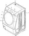
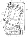
図1は、具体的構成を示すバッフルの形状を示す図。図2は、ドラム式洗濯乾燥機の外
観斜視図。図3は、ドラム式洗濯乾燥機の全体構成を示す縦断側面図。そして図4は、ド
ラム式洗濯乾燥機のドラムを前方から示す図である。
図2、図3に示すように、ドラム式洗濯乾燥機は全体として矩形箱状をしており、その
外郭を形成する外箱1の前面部1aには円形状の洗濯物投入口4を形成し、この洗濯物投
入口4には開閉可能な扉5が取り付けられている。
そして外箱1内部には、水槽6が配設されていて、この水槽6は前面に開口部を有する
ドラム状を成すもので、外箱1の底面部に左右一対のサスペンション7を介して横向きに
弾性支持されており、その支持形態は、前面の開口部に向かって上昇傾斜する形状である
。
この水槽6の前部には環状をなす水槽カバー6aが設けられていて、後述するようにこ
の水槽カバー6aと洗濯物投入口4との間がベロー8によって水密に連通接続されている
。
水槽6の閉塞された底面を構成する後端面部6c(図3中、右側の端面部)は十分な機
械的強度を有し、その背面にモータ15が取付けられている。またその上部には、後述す
る給気口16が形成されている。そのほか、水槽6の側面最底部には排水口17が形成さ
れており、その下流には排水弁18が取付けられ、その先には排水ホース19が接続され
ている。また水槽6の上面には可撓性ホース20が接続されており、この可撓性ホース2
0は外箱1の前方上部に設けられた洗剤ケース21を介して後部の給水装置22と繋がり
、給水装置22の給水口23と繋がっている。
また水槽6の内部には、所定の間隙を有して径小のドラム30が配設されている。この
ドラム30の閉塞された底面は、強度十分の板厚とした例えば金属製のドラム支え30b
として機能するように設けられている。このドラム支え30b中心部に取付けられたドラ
ムシャフト30cは、水槽6の底部の中心部から前記モータ15に取付けられている。こ
れにより、ドラム30は、水槽6と同じ傾斜をもって水槽6に回転可能に支持される。
Hereinafter, an embodiment in which the drum type washing machine of the present invention is applied to a drum type washing and drying machine will be described with reference to the drawings.
FIG. 1 is a diagram showing the shape of a baffle showing a specific configuration. FIG. 2 is an external perspective view of the drum type washing and drying machine. FIG. 3 is a longitudinal side view showing the overall configuration of the drum type washing and drying machine. And FIG. 4 is a figure which shows the drum of a drum type washing-drying machine from the front.
As shown in FIGS. 2 and 3, the drum-type washing and drying machine has a rectangular box shape as a whole, and a circular laundry input 4 is formed on the front surface 1a of the outer box 1 forming the outer shell. A
A water tank 6 is disposed inside the outer box 1, and this water tank 6 has a drum shape having an opening on the front surface. The water tank 6 faces sideways via a pair of left and right suspensions 7 on the bottom surface of the outer box 1. The support form is a shape that rises and inclines toward the opening on the front surface.
An annular
The rear
0 is connected to a rear
A small-
It is provided to function as. The
また前記ドラム30には、周壁部とドラム支え30bのほぼ全域に通水および通風が可
能な多数の孔31が設けられており(図3では一部のみ図示)、また胴部の内周部の数か
所に後述するバッフル32が取付けられている。
またドラム30の前部には、ドラムカバー30aが取り付けられている。このドラムカ
バー30aは、ドラム30の開放された前面の周縁部に装着されたもので、中央部に洗濯
物出入口33を有するリング状を成しており、耐熱材で構成されている。
また上記した水槽カバー6aは、中央部に開口部を有するリング状を成して、鉄板やス
テンレス板等の金属、又はガラスや合成樹脂などの耐熱性である剛性材で構成されている
。
この水槽カバー6aは、その上部に排気口40を形成しており、その外部には排気口4
0を覆い、連通する排気ダクト41が設けられている。
この排気ダクト41は、水槽カバー6aを囲繞するように環状に設けられており、その
排気ダクト41の下部は、蛇腹状部を有する可撓性ダクト42を介して、水槽6の下方に
設けられた乾燥ユニット用ダクト43に接続されている。
この乾燥ユニット用ダクト43は外箱1内に前部から後方へ延びていて、その後部にフ
ァンケーシング44が設けられている。ファンケーシング44の上方に形成される吐出口
45には、蛇腹状部を有する可撓性ダクト46を介して給気ダクト47に接続されている
。給気ダクト47は、図5に示すように、モータ15を囲繞するようにして、ドラム30
の回転方向に沿ってほぼ円弧状に延びていて、その先端部が水槽6の後端面部6cの上部
において前記給気口16と接続されている。
Further, the
A
The
The
An
The
The
The tip end portion of the water tank 6 is connected to the
ここで、水槽カバー6aの排気口40に接続された排気ダクト41、可撓性ダクト42
、乾燥ユニット用ダクト43、ファンケーシング44、可撓性ダクト46、そして、水槽
6の給気口16に接続された給気ダクト47により、水槽6内と連通した循環送風路48
を構成している。循環送風路48のうちファンケーシング44内には、送風機49を構成
するファン49aが配設され、ファンケーシング44の外部にファンモータ49bが配設
されている。
乾燥ユニット用ダクト43内には、ヒートポンプ機構50の蒸発器(エバポレータ)5
1と凝縮器(コンデンサ)52とが配設されている。ヒートポンプ機構50は、周知のよ
うに、圧縮機(コンプレッサ)53と、凝縮器52と、図示しないキャピラリチューブ(
絞り)と、蒸発器51を順にパイプによりサイクル状に接続して冷凍サイクルを構成する
もので、圧縮機53を駆動することに伴い、冷媒がそれらを順に通って循環するようにな
っている。このとき、凝縮器52においては、冷媒が熱を放出して液化するようになって
おり、この凝縮器52は循環空気の加熱手段として機能する。また、蒸発器51において
は、冷媒が蒸発する際に周囲の熱を奪うことにより周囲を冷却するようになっており、こ
の蒸発器51は循環空気の冷却手段として機能する。そしてこの場合、送風機49や凝縮
器52および蒸発器51等のヒートポンプ機構50により乾燥機能手段を構成するもので
、これらは外箱1内において水槽6の下方に配設されており、従って、外箱1内の下部に
配置されている。また乾燥ユニット用ダクト43に比して高さ方向に大きい圧縮機53は
、外箱1の前面1aに向かって上昇傾斜する水槽6の下方前方に配置されている。
Here, the
The
Is configured. A
In the
1 and a condenser (condenser) 52 are disposed. As is well known, the
The refrigeration cycle is configured by connecting the
ここで外箱1の前面部1aおよびベロー8の取付手段について説明する。
まず、前述したように外箱1の前面部1aに開閉可能な扉5が取り付けられている。こ
の前面部1aは、前板としての前面パネル2と、電源等のスイッチが配置された操作パネ
ル3とから構成されていて、それぞれ、安価なポリプロピレンで形成されている。
その前面部1aの中央には、図2、図3に示すように前記扉5を収納する円形状で中央
が窪んだ形状の投入口枠60が設けられている。そしてこの前面パネル2には扉5の閉鎖
状態を解除するオープンボタン65(図2参照)が備えてあり、プッシュすることにより
扉5が開放されるようになっている。
また扉5は、図3に示すように、洗濯物投入口4の形状に合わせた円形の形状を有して
おり、投入口枠60に収納されて、扉5の閉鎖時には扉5の前面が前面パネル2と略面一
になるように構成されている。
そしてこの扉5の左側端部に取り付けられたヒンジ63により手前に回動することによ
って、洗濯物投入口4を開閉するようになっている。また、この扉5の右側端部には閉鎖
状態保持用のフック64が設けられている。
更に、扉5の中央部は洗濯物投入口4と同程度の大きさの透視部である透視窓66が設
けられている。この透視窓66は、図4に示すように例えば扉5の前面に前面ガラス67
と、扉5の後面に前面ガラス67に平行に設けられた後面ガラス68とによる2重構造を
なして構成されている。
Here, a means for attaching the front face 1a of the outer box 1 and the bellows 8 will be described.
First, as described above, the openable /
As shown in FIGS. 2 and 3, a circular
As shown in FIG. 3, the
Then, the laundry input port 4 is opened and closed by rotating forward by a hinge 63 attached to the left end of the
Further, a see-through
And a
一方、シール部材としてのベロー8は、図3に示すように例えば水槽6からの振動を低
減する弾性材で、耐薬品性にも優れたエチレン・プロピレン系の合成ゴム(略称EPDM
)で筒状に形成されており、その後方の取付後部が前記水槽カバー6aの前端部に囲繞し
て、この取付後部を環状のベローリングにて取り付けられている。この取付後部の前方は
蛇腹部状に形成されていて水槽6からの振動を吸収するように形成されている。
対してベロー8の前方は、洗濯物投入口4付近で内周方に延出されたリング状の起立部
が形成されていて、扉5の裏面たる後面ガラス68が起立部に接触することで扉5と水槽
6を水密にする構成をしている。
On the other hand, the bellows 8 as a sealing member is an elastic material that reduces vibration from the water tank 6, for example, as shown in FIG. 3, and is an ethylene / propylene synthetic rubber (abbreviated as EPDM) that has excellent chemical resistance.
), A rear mounting rear portion surrounds the front end portion of the
On the other hand, the front of the bellows 8 is formed with a ring-like standing portion extending in the inner circumferential direction in the vicinity of the laundry insertion port 4, and the
ここでドラム30に設けたバッフル32について説明する。
このバッフル30は図4に示すようにドラム30の内周壁に突状に3つ形成されており
、それぞれ120度ずつ乖離して設置されている。
バッフル32は、図1に示すように合成樹脂(例えばポリプロピレン)により一体に成
形され断面がT字状を為すもので、本体の中央に突状部32aが設けられていて、その両
側面に薄板状のグリップ部32bが設けられることで、突状部32aから両方向に階段状
をなす構成となっている。またこの突状部32aとグリップ部32bは略直角に交差する
ように構成されている。
このバッフル32は、突状部32aがドラム30の半径の15%程度の長さとなってお
り、突状部32aの高さとグリップ部32b上面の長さが略同じになるように構成されて
いる。
Here, the
As shown in FIG. 4, three
As shown in FIG. 1, the
The
次に上記構成の作用を説明する。
まず、本来の洗濯乾燥機能としては、周知のように、洗い、すすぎ、脱水、乾燥行程を
実行するものである。
洗濯を行う場合には、扉5を開いて洗濯物(図示せず)を投入口枠60の洗濯物投入口
4を介して、洗濯物出入口33からドラム30内に投入して収容する。そして洗剤ケース
21内に洗剤を収容し、操作パネル3の操作ボタンにおいて、例えば標準コースが選択さ
れた場合には、図示しない制御装置が有する制御プログラムに基づき、洗い、すすぎ、脱
水、乾燥の各行程が自動的に行なわれる。
洗い行程では、まず排水弁18を閉じ、給水装置22から水が洗剤ケース21及び可撓
性ホース20を介して水槽6内に供給されて貯留される。このとき、洗剤ケース21内に
収容された洗剤も水と共に水槽6内に供給される。
そして、モータ15が駆動されて、ドラム30が低速で正逆両方向に回転されることに
より、洗濯物はバッフル32の突状部32aが洗濯水を押すことによって生起された複雑
な水流により撹拌されるとともに、突状部32aによりドラム30の回転方向に移動され
て、バッフル32が上方に位置したときに、重力によりドラム30下方に落ちて、ドラム
30の底面にたたきつけられることによりドラム30内を複雑に移動して洗浄される。
さらにこのとき、洗濯物はバッフル32の薄板状のグリップ部32bの側面にも引掛か
りドラム30の回転方向に押されることにより、突状部32aの側面とグリップ部32b
の側面とにより、2段の階段状の側面部に押されることにより、より多くの洗濯物が接触
して、ドラム30の回転力が洗濯物に伝達させることができる。
またこの洗濯物が図4に示すようにバッフル32のグリップ部32b上面に接触してい
るときは、グリップ部32bの摩擦力により洗濯物がグリップ部32bとの接触面で引っ
かかり、図4に示すようにグリップ部32bの回転速度Bと略同じ回転速度Cで移動し、
グリップ部32bに追随して回転する状況も生ずる。
そしてこのグリップ部32bの上面の面積はバッフル32の突状部32aと略同じ長さ
に形成されていることにより、洗濯物が突状部32aの側面とグリップ部32bの上面に
両面に接触して、突状部32aの側面で押される力と、グリップ部32bの上面で回転に
追随する摩擦力F1との両方の力によりドラム30の回転力を伝達している。
また突状部32aを半回転方向に乗り越えて移動した洗濯物にあっては、乗り越えた後
グリップ部32bの上面に接触することにより、洗濯物と当該グリップ部32bとの摩擦
力F2で回転方向に移動する。また洗濯物がグリップ部32bの上面で相対的に移動する
場合には、その摺動動作(すべり摩擦や回転摩擦)により、洗濯物が洗浄される。
そしてドラム30の回転が、モータの駆動により逆転する瞬間には、洗濯物は、回転時
の衝撃によって、バッフル32から離れ、洗濯物のドラム30に対する接触面が切り替わ
る。次いで別の洗濯物が再びバッフル32に引っかかり移動する。
このように洗濯物は、洗い行程中にバッフル32に引っかかったり、離れたりして、随
時バッフル32の回転速度に追随した速い回転速度を得ている。
Next, the operation of the above configuration will be described.
First, as the known washing and drying function, as is well known, washing, rinsing, dehydration, and a drying process are executed.
When washing is performed, the
In the washing process, first, the
Then, when the
Furthermore, at this time, the laundry is also hooked on the side surface of the thin plate-
By pushing against the side surfaces of the two stepped steps, more laundry comes into contact with each other, and the rotational force of the
When the laundry is in contact with the upper surface of the
There also occurs a situation in which the
And the area of the upper surface of this
Further, in the laundry that has moved over the protruding
Then, at the moment when the rotation of the
In this way, the laundry is caught or separated from the
洗い行程が終了すると、排水弁18を開放して水槽6内の水を排出した後、中間脱水を
行なう。中間脱水は、モータ15によりドラム30を一方向に高速回転させることによっ
て洗濯物に含まれた水を遠心力により孔31から排出させて行われる。この中間脱水が終
了するとつづいてすすぎ行程が行われる。すすぎ行程は、給水時に洗剤を使用しないとこ
ろ以外は洗い行程と同様に行なわれる。すすぎ行程が終了すると、最終脱水行程が行なわ
れる。最終脱水行程は、中間脱水行程と同様に、水槽6内の水を排出した後、モータ15
によりドラム30を一方向に高速回転させることによって行われる。
洗濯物は、そのバッフル32の高さと容積を従来のものより小さく形成しており(本実
施例では突状部32aの高さをドラム30の半径方向の15%程度にしている)、遠心力
によりドラム30内周壁に張り付く洗濯物はバッフル32の側面にだけ多くの洗濯物がと
どまるといった重量バランスが悪い状態が生じず、ドラム30内周壁全体に洗濯物が分布
する。
When the washing process is completed, the
Is performed by rotating the
In the laundry, the height and volume of the
この最終脱水行程が終了すると、次に乾燥行程が行なわれる。この乾燥行程では、モー
タ15によりドラム30を低速で正逆両方向に回転させると共に、送風機49、及びヒー
トポンプ機構50の圧縮機53を駆動させる。このうち、送風機49を駆動すると、ファ
ン49aの送風作用により、図3の実線の矢印Aで示すように、乾燥ユニット用ダクト4
3内の空気がファンケーシング44側に吸引されると共に、吐出口45から可撓性ダクト
46を介して給気ダクト47側へ吐出される。
給気ダクト47へ吐出された空気は、給気口16から水槽6内へ供給される。水槽6内
へ供給された空気の多くは、ドラム30の孔31を通してドラム30内に供給される。
ドラム30内及び水槽6内の空気は、水槽6の開口部に向かって流れ、扉5の後面ガラ
ス68やベロー8にぶつかり、水槽6前部の排気口40から排気ダクト41側へ排出され
る。排気ダクト41側へ排出された空気は、下方の可撓性ダクト42を通り、乾燥ユニッ
ト用ダクト43に戻されるようにして循環される。
また、圧縮機53が駆動されると、圧縮機53から高温高圧の冷媒が凝縮器52に流れ
、ここで放熱して液化する。このとき、乾燥ユニット用ダクト43の凝縮器52を通る空
気がその凝縮器52により加熱される。また、液化した冷媒は、キャピラリチューブを通
過して減圧された後、蒸発器51に流れ、ここで周囲の熱を奪って気化する。このとき、
乾燥ユニット用ダクト43の蒸発器51を通る空気がその蒸発器51により冷却される。
When this final dehydration process is completed, a drying process is performed next. In the drying process, the
3 is sucked to the
The air discharged to the
The air in the
When the
The air passing through the
蒸発器51で気化した冷媒は圧縮機53に戻り、再び圧縮されて高温高圧の冷媒となって
吐出される。
このようにして、凝縮器52により加熱された温風が、ドラム30内に供給されること
により、ドラム30内の洗濯物を加熱すると共に、洗濯物の水分を奪い、洗濯物を乾燥さ
せる。そして、水分を奪った空気が、乾燥ユニット用ダクト43の蒸発器51を通る過程
で冷却されて、その空気に含まれる水分が凝縮して除湿される。除湿された空気が、再び
凝縮器52を通る過程で加熱されて温風化され、温風がドラム30内に供給されるという
ように循環する。このように水槽6内の空気が循環送風路48を通して循環されることに
伴い、ドラム30内の洗濯物が乾燥される。
The refrigerant vaporized by the
In this way, the warm air heated by the
そしてこの乾燥行程における洗濯物は、ドラム30の回転によって、洗い行程時と同様
に、洗濯物にドラム30の回転を伝達して、洗濯物をドラム30の上方に移動させ、そこ
から重力方向に洗濯物を落とすことにより、熱風が当たりやすくする。
またこの動作と併せて、乾燥行程の際ではドラム30をモータの制御で交互に正逆回転
させることにより洗濯物をほぐしながら、熱風を当てるが、このほぐし動作により洗濯物
は摩擦力のあるグリップ部32bに引っかかることでバッフル32のほぐす動作をさせる
ほぐし力(例えば、ドラム30の回転が、逆転する瞬間に、逆転時の衝撃によって洗濯物
に加わる力)が伝わり、洗濯物がそのバッフル32の場所から移動することで洗濯物と熱
風との接触面が切り替えられる。
このほぐし動作を繰り返すことにより、熱風は、これら洗濯物が移動することによって
できた隙間を通って洗濯物から水分を奪い洗濯物を乾燥させる。
以上により、洗濯、乾燥運転が終了する。
Then, in the drying process, the laundry transmits the rotation of the
In addition to this operation, during the drying process, the
By repeating this unwinding operation, the hot air removes moisture from the laundry through the gap formed by the movement of the laundry and dries the laundry.
Thus, the washing and drying operation is completed.
上記した実施形態によれば、次のような効果を得ることができる。
バッフル32を突状部32aと、その両側面に設けた薄板状のグリップ部32bとから
構成し、もって突状部32aから両方向に階段状をなす構成としたことで、洗濯物の接触
面積を広げることができ、さらには階段状であるため、階段状のそれぞれの側面で洗濯物
を捉えることができ、洗濯物へのドラム30の回転伝達力を効率的に伝達することができ
る。またバッフル32の断面をT字状に形成した為、容易にバッフル32を成形できる。
According to the above-described embodiment, the following effects can be obtained.
The
そしてグリップ部32bを設けたため、洗濯物が突状部32aの側面とグリップ部32
bの上面に両面に接触して、突状部32aの側面で押される力と、グリップ部32bの上
面で回転に追随する摩擦力F1との両方の力によりドラム30の回転力を伝達することが
できる。
また突状部32aを乗り越えて移動した洗濯物は、乗り越えた後にグリップ部32bの
上面に接触することにより、洗濯物と当該グリップ部32bとの摩擦力F2で回転方向に
移動させることができる。さらには洗濯物がグリップ部32bの上面で相対的に移動する
場合には、その摺動動作(すべり摩擦や回転摩擦)により、洗濯物を洗浄することができ
る。
なお、突状部32aとグリップ部32bを略直角に交差するように構成したため、洗濯
物がより引っ掛かりやすく、伝達力を高めることができる。
And since the
b is in contact with both surfaces of the upper surface of b, and the rotational force of the
Also, the laundry that has moved over the protruding
In addition, since it comprised so that the
またこのバッフル32の構成による洗濯物への回転伝達力の強さから、バッフル32の
形状を、従来の構成のようにドラムの容積に対するバッフルの容積を大きくする必要がな
く、例えばドラム30の半径長さに対して15%程度の長さにすることができる。そのた
め、ドラム30内の洗濯物収容容積が広くなり、洗濯物を多く洗うことができる。
同様にバッフル32の長さを必要以上に長くしなくても、洗濯物に回転力を伝達できる
為、余計な洗濯水までもかきあげることがなくなり、余分な電力使用量が発生しない。ま
たバッフル32の容積を必要以上に大きくすることはないため、バッフル32の材料費も
軽減される。
In addition, the
Similarly, even if the length of the
また脱水行程では、バッフル32の容積を小さくできることから、ドラム30の遠心力
によりドラム30内周壁に張り付く洗濯物はバッフル32の側面にだけ多くの洗濯物がと
どまるといった重量バランスが悪い状態が生じず、ドラム30内周壁全体に洗濯物が分布
して、より安定した重量バランスを実現することができる。
そして、乾燥行程においては、バッフル32に洗濯物が引っ掛かる摩擦力が強くなり、
その摩擦力によりパルセータのほぐし力が伝わりやすく、洗濯物がバッフル32の回転に
対して移動しやすく、洗濯物の接触面が変わりやすいため、熱風の洗濯物への風通しがよ
くなり、乾燥効率が向上する。
その他、本発明は上記実施例に限定されるものではなく、実施に際して本発明の要旨を
逸脱しない範囲で種々変更して実施できるものである。
In addition, since the volume of the
In the drying process, the frictional force that the laundry is caught on the
Because of the frictional force, the loosening force of the pulsator is easily transmitted, the laundry is easy to move with respect to the rotation of the
In addition, the present invention is not limited to the above-described embodiments, and various modifications can be made without departing from the spirit of the present invention.
図中、1は外箱、1aは前面部、2は前面パネル、3は操作パネル、4は洗濯物投入口、
5は扉、6は水槽、6aは水槽カバー、6bは開口部、6cは後端面部、7はサスペンシ
ョン、8はベロー、15はモータ、16は給気口、17は排水口、18は排水弁、19は
排水ホース、20は可撓性ホース、21は洗剤ケース、22は給水装置、23は給水口、
30はドラム、30aはドラムカバー、30bはドラム支え、30cはドラムシャフト、
31は孔、32はバッフル、32aは突状部、32bはグリップ部、33は洗濯物出入口
、40は排気口、41は排気ダクト、42は可撓性ダクト、43は乾燥ユニット用ダクト
、44はファンケーシング、45は吐出口、46は可撓性ダクト、47は給気ダクト、4
8は循環送風路、49は送風機、49aはファン、49bはファンモータ、50はヒート
ポンプ機構、51は蒸発器、52は凝縮器、53は圧縮機、60は投入口枠、61は鍔部
、62は窪み部、63はヒンジ、64はフック、65はオープンボタン、66は透視窓、
67は前面ガラス、68は後面ガラス、を示す。
In the figure, 1 is an outer box, 1a is a front part, 2 is a front panel, 3 is an operation panel, 4 is a laundry inlet,
5 is a door, 6 is a water tank, 6a is a water tank cover, 6b is an opening, 6c is a rear end surface part, 7 is a suspension, 8 is a bellows, 15 is a motor, 16 is an air inlet, 17 is a water outlet, 18 is a water drain Valve, 19 drain hose, 20 flexible hose, 21 detergent case, 22 water supply device, 23 water supply port,
30 is a drum, 30a is a drum cover, 30b is a drum support, 30c is a drum shaft,
31 is a hole, 32 is a baffle, 32a is a protrusion, 32b is a grip part, 33 is a laundry doorway, 40 is an exhaust port, 41 is an exhaust duct, 42 is a flexible duct, 43 is a duct for a drying unit, 44 Is a fan casing, 45 is a discharge port, 46 is a flexible duct, 47 is an air supply duct, 4
8 is a circulation air passage, 49 is a blower, 49a is a fan, 49b is a fan motor, 50 is a heat pump mechanism, 51 is an evaporator, 52 is a condenser, 53 is a compressor, 60 is an inlet frame, 61 is a collar, 62 is a recess, 63 is a hinge, 64 is a hook, 65 is an open button, 66 is a see-through window,
Claims (2)
この水槽の内側に設けられ回転駆動するドラムと、
このドラムの内周壁に、洗濯物に前記ドラムの回転力を伝達する突状のバッフルを備え、
このバッフルは断面が階段状に形成されていることを特徴とするドラム式洗濯機。 A tank,
A drum that is provided inside the aquarium and that is driven to rotate;
Provided on the inner peripheral wall of this drum is a protruding baffle that transmits the rotational force of the drum to the laundry,
A drum type washing machine characterized in that the baffle has a stepped cross section.
濯機。 2. The drum type washing machine according to claim 1, wherein the baffle has a T-shaped cross section.
Priority Applications (1)
| Application Number | Priority Date | Filing Date | Title |
|---|---|---|---|
| JP2006093965A JP2007267784A (en) | 2006-03-30 | 2006-03-30 | Drum type washing machine |
Applications Claiming Priority (1)
| Application Number | Priority Date | Filing Date | Title |
|---|---|---|---|
| JP2006093965A JP2007267784A (en) | 2006-03-30 | 2006-03-30 | Drum type washing machine |
Publications (1)
| Publication Number | Publication Date |
|---|---|
| JP2007267784A true JP2007267784A (en) | 2007-10-18 |
Family
ID=38671215
Family Applications (1)
| Application Number | Title | Priority Date | Filing Date |
|---|---|---|---|
| JP2006093965A Pending JP2007267784A (en) | 2006-03-30 | 2006-03-30 | Drum type washing machine |
Country Status (1)
| Country | Link |
|---|---|
| JP (1) | JP2007267784A (en) |
Cited By (2)
| Publication number | Priority date | Publication date | Assignee | Title |
|---|---|---|---|---|
| JP2009233114A (en) * | 2008-03-27 | 2009-10-15 | Fujifilm Corp | Endoscope-washing/disinfecting apparatus |
| CN105019208A (en) * | 2014-04-16 | 2015-11-04 | 青岛胶南海尔洗衣机有限公司 | Clothes dryer drum and clothes dryer |
Citations (3)
| Publication number | Priority date | Publication date | Assignee | Title |
|---|---|---|---|---|
| JPS5739881A (en) * | 1980-08-21 | 1982-03-05 | Inamoto Seisakusho Kk | Washing hydroextracting machine |
| JPH0497784A (en) * | 1990-08-17 | 1992-03-30 | Matsushita Electric Ind Co Ltd | Drum type washing machine |
| JPH09215894A (en) * | 1996-02-15 | 1997-08-19 | Matsushita Electric Ind Co Ltd | Washing machine |
-
2006
- 2006-03-30 JP JP2006093965A patent/JP2007267784A/en active Pending
Patent Citations (3)
| Publication number | Priority date | Publication date | Assignee | Title |
|---|---|---|---|---|
| JPS5739881A (en) * | 1980-08-21 | 1982-03-05 | Inamoto Seisakusho Kk | Washing hydroextracting machine |
| JPH0497784A (en) * | 1990-08-17 | 1992-03-30 | Matsushita Electric Ind Co Ltd | Drum type washing machine |
| JPH09215894A (en) * | 1996-02-15 | 1997-08-19 | Matsushita Electric Ind Co Ltd | Washing machine |
Cited By (2)
| Publication number | Priority date | Publication date | Assignee | Title |
|---|---|---|---|---|
| JP2009233114A (en) * | 2008-03-27 | 2009-10-15 | Fujifilm Corp | Endoscope-washing/disinfecting apparatus |
| CN105019208A (en) * | 2014-04-16 | 2015-11-04 | 青岛胶南海尔洗衣机有限公司 | Clothes dryer drum and clothes dryer |
Similar Documents
| Publication | Publication Date | Title |
|---|---|---|
| JP4715695B2 (en) | Drying unit and drying device | |
| JP6023976B2 (en) | Clothes dryer | |
| JP2008006179A (en) | Drum type washing machine | |
| JP2005177505A (en) | Washing machine cum drying machine | |
| JP4685588B2 (en) | Washing and drying machine | |
| JP2005304988A (en) | Washing and drying machine | |
| JP5948608B2 (en) | Clothes dryer | |
| JP2007267784A (en) | Drum type washing machine | |
| WO2013111589A1 (en) | Drum-type washing and drying machine | |
| JP2010029521A (en) | Washing/drying machine | |
| JP2012071069A (en) | Drying machine and washing and drying machine | |
| JP5600779B2 (en) | Washing and drying machine | |
| WO2014024346A1 (en) | Washer/dryer | |
| JP2010082345A (en) | Drum type washing and drying machine | |
| JP2005052534A (en) | Washing and drying machine | |
| JP2017144341A (en) | Dryer | |
| JP2010075216A (en) | Drying machine and washing and drying machine | |
| JP2008284142A (en) | Clothes dryer | |
| JP6175654B2 (en) | Drying equipment | |
| JP2003205193A (en) | Washing drying machine | |
| JP5873979B2 (en) | Drying equipment | |
| JP2020039752A (en) | Washing and drying machine | |
| JP5602802B2 (en) | Drying equipment | |
| JP2013192659A (en) | Drying machine | |
| JP2008006063A (en) | Drum-type washing and drying machine |
Legal Events
| Date | Code | Title | Description |
|---|---|---|---|
| A621 | Written request for application examination |
Free format text: JAPANESE INTERMEDIATE CODE: A621 Effective date: 20080905 |
|
| A977 | Report on retrieval |
Free format text: JAPANESE INTERMEDIATE CODE: A971007 Effective date: 20101025 |
|
| A131 | Notification of reasons for refusal |
Free format text: JAPANESE INTERMEDIATE CODE: A131 Effective date: 20101029 |
|
| A521 | Written amendment |
Free format text: JAPANESE INTERMEDIATE CODE: A523 Effective date: 20101208 |
|
| A02 | Decision of refusal |
Free format text: JAPANESE INTERMEDIATE CODE: A02 Effective date: 20110204 |