JP2007265902A - Electrodeless discharge lamp and luminaire using it - Google Patents
Electrodeless discharge lamp and luminaire using it Download PDFInfo
- Publication number
- JP2007265902A JP2007265902A JP2006091653A JP2006091653A JP2007265902A JP 2007265902 A JP2007265902 A JP 2007265902A JP 2006091653 A JP2006091653 A JP 2006091653A JP 2006091653 A JP2006091653 A JP 2006091653A JP 2007265902 A JP2007265902 A JP 2007265902A
- Authority
- JP
- Japan
- Prior art keywords
- discharge
- lighting
- induction coil
- induction
- arc tube
- Prior art date
- Legal status (The legal status is an assumption and is not a legal conclusion. Google has not performed a legal analysis and makes no representation as to the accuracy of the status listed.)
- Ceased
Links
Images


Abstract
Description
本発明は、放電容器内部に電極を搭載せずに、高周波を用いた誘導電界により放電を発生、維持させる形式の無電極放電灯装置に関する。また、無電極放電灯装置が搭載された照明器具に関する。 The present invention relates to an electrodeless discharge lamp apparatus of a type in which a discharge is generated and maintained by an induction electric field using a high frequency without mounting an electrode inside the discharge vessel. Moreover, it is related with the lighting fixture by which an electrodeless discharge lamp apparatus is mounted.
近年の省エネ、省資源化への社会的な背景を受け、より長寿命、高効率なランプの開発が望まれている。このような要請に応えるランプとして、特に、メンテナンスフリーの要望の高い施設や屋外照明、または、UV(紫外線)利用などの特殊用途向けとして、放電容器空間内部に電極を用いないことを特徴とした無電極放電灯装置が実用化されつつある。 In response to the recent social background of energy saving and resource saving, it is desired to develop a lamp having a longer life and higher efficiency. As a lamp that meets such demands, it is characterized by the fact that no electrode is used inside the discharge vessel space, especially for facilities requiring high maintenance-free requirements, outdoor lighting, or special applications such as UV (ultraviolet) use. Electrodeless discharge lamp devices are being put into practical use.
現在、一般照明用光源として広く用いられている蛍光ランプや高輝度高圧放電ランプでは、点灯時間経過に伴う電極やフィラメントの劣化が寿命を制限する最大の要因であった。放電容器空間内部に電極を持たない無電極放電灯では、上記のような劣化要因が無いため長寿命が期待できる。また、この無電極放電灯を一般照明用として普及させるためには、現在の照明用光源として最も普及している直管タイプの蛍光ランプと同様に、細く、長い線状光源の形態で実現することが望まれている。これは既存の直管用照明器具が最も多く使われている理由として、管軸方向に対して均一な発光(輝度)で、かつ、器具効率(照明器具からの光の取り出し効率)、配光制御に優れているためである。 At present, in fluorescent lamps and high-intensity high-pressure discharge lamps that are widely used as light sources for general illumination, deterioration of electrodes and filaments with the passage of lighting time is the largest factor that limits the life. An electrodeless discharge lamp having no electrode inside the discharge vessel space can be expected to have a long life because there is no deterioration factor as described above. Moreover, in order to make this electrodeless discharge lamp popular for general illumination, it is realized in the form of a thin and long linear light source, similar to the straight tube type fluorescent lamp that is most popular as the current illumination light source. It is hoped that. This is because the existing straight tube luminaires are most frequently used, with uniform light emission (luminance) in the tube axis direction, fixture efficiency (light extraction efficiency from the luminaire), and light distribution control. It is because it is excellent in.
従来の細長い光源を実現するための無電極放電灯は、放電容器の回りに、複数個の誘導コイルを巻回することにより、コイルに高周波電流を供給することによって生じる誘導電磁場によって、放電容器内の可電離気体を電離、放電させ、安定したプラズマを持続させるものがあった(例えば、特許文献1参照)。 A conventional electrodeless discharge lamp for realizing a long and narrow light source includes a plurality of induction coils wound around a discharge vessel, and an induction electromagnetic field generated by supplying a high-frequency current to the coils. Some of these ionizable gases are ionized and discharged to maintain a stable plasma (see, for example, Patent Document 1).
図10は、特許文献1に記載された従来の無電極放電灯装置を示すものである。
FIG. 10 shows a conventional electrodeless discharge lamp device described in
図10において、放電容器1101〜1104は光透過性の材質で気密に封止成形されており、通常、ソーダライムガラスやホウケイ酸ガラス、石英ガラスなどのガラス材料がその光源の用途によって使い分けられている。放電容器内部には、水銀およびクリプトン等の希ガス(図示しない)が封入され、発光管が実現されている。また、一般照明用途であれば、放電により放射された紫外線を可視光に変換するために、放電容器1101〜1104の内壁には蛍光体が塗布されて、発光管が実現されている。
In FIG. 10, the
誘導コイル1105〜1108は、放電容器1101〜1104に各々巻回され、細長い外管1109内においてその長手方向を軸として一列に設置されている。誘導コイル1105〜1108へは、高周波電源から、誘導コイルに電力が供給されるよう負荷側とのインピーダンスマッチングをとるための整合回路を介して接続されている(いずれも図示しない)。
The
高周波電源は、商用電源から供給される電力を数10kHz〜数10MHzの高周波に変換するインバータ回路により構成され、前記誘導コイル1105〜1108へと高周波電力を供給している。
The high frequency power source is configured by an inverter circuit that converts electric power supplied from a commercial power source into a high frequency of several tens of kHz to several tens of MHz, and supplies the
このように構成される無電極放電灯装置は、主にUV殺菌灯などの特殊用途を中心として考案されており、その目的から、均一かつ幅広く紫外線を照射させるために、1つ、または、複数個の放電容器が直管状の外管内部に一直線上に配設されて構成されている。通常、この種の分野では、放電管内に電極を備えた直管形状の殺菌ランプが使用されることが多く、その概観的な形態を模したものである。 The electrodeless discharge lamp apparatus configured as described above has been devised mainly for special applications such as UV germicidal lamps. For that purpose, one or a plurality of electrodeless discharge lamp apparatuses are used in order to irradiate ultraviolet rays uniformly and widely. Each discharge vessel is arranged in a straight line inside a straight tubular outer tube. Usually, in this type of field, a straight tube-shaped sterilization lamp provided with an electrode in a discharge tube is often used, which imitates the general form.
図10に示すような無電極放電灯装置においては、放電の開始時には高周波電源(図示しない)から供給される電流によって、誘導コイル1105〜1108が高周波電磁場を発生し、放電容器1101内において誘導コイル1105〜1108から発生される電磁界が最も強くなる巻線近傍において、放電の種火が発生する(E放電と呼ばれるプラズマ密度の低い微弱な放電:以下、E放電と称する)。
In the electrodeless discharge lamp apparatus as shown in FIG. 10,
さらに、放電容器1101内に誘導される誘導高周波電磁場が、封入された希ガス及び水銀原子の電離を加速させることで、誘導コイル1105〜1108と同心円状の放電リングプラズマが形成され、誘導コイル1105〜1108から効率よくプラズマへエネルギーを伝達させることができる(H放電と呼ばれるプラズマ密度の高い放電:以下、H放電と称する)。
Further, the induction high frequency electromagnetic field induced in the
このようにして、微弱でプラズマ密度の低いE放電から、約1桁プラズマ密度の高いH放電へモードジャンプさせる。プラズマ中では、水銀の原子が電子によって共鳴準位に励起され、その励起された水銀原子が基底状態に脱励起する際に、主に紫外線が放射される。この紫外線のうちの主に波長253.7nmの共鳴線が、殺菌ランプなどのUV利用ではそのまま照射され、また、一般照明用途においては、放電容器1101〜1104の内壁に塗布された蛍光体層(図示しない)によって可視光に変換される。
In this way, mode jump is performed from the weak E discharge having a low plasma density to the H discharge having a plasma density of about one digit higher. In the plasma, mercury atoms are excited to resonance levels by electrons, and ultraviolet rays are mainly emitted when the excited mercury atoms are deexcited to the ground state. Among the ultraviolet rays, a resonance line mainly having a wavelength of 253.7 nm is irradiated as it is when UV light such as a sterilizing lamp is used, and in a general illumination application, a phosphor layer (applied to the inner walls of the
E放電の領域では、一般的に、プラズマ密度が低いため、発光に必要な紫外線の放射量も相対的に低く、ランプの放電形態としては使用されない。さらに、誘導コイルにかかる電圧が高く、コイルに流れる電流値も高くなることから、コイル部分での損失が大きい。そのため、コイルにおける発熱によるコイルの耐熱寿命特性の低下や、コイル巻線間での絶縁破壊に対する信頼性の低下を引き起こす。さらに、誘導コイルへより大きな電流、電圧を供給しなくてはならないため、整合回路部にかかる電気的ストレスが大きくなる。これにより、点灯回路の寿命・信頼性が著しく低下することとなる。そのため、ランプとして実際に使用される領域は前述のH放電である。 In the region of E discharge, since the plasma density is generally low, the amount of ultraviolet radiation required for light emission is relatively low and is not used as a discharge form of a lamp. Furthermore, since the voltage applied to the induction coil is high and the current value flowing through the coil is also high, the loss in the coil portion is large. Therefore, the heat-resistant life characteristic of the coil is reduced due to heat generation in the coil, and the reliability against dielectric breakdown between the coil windings is reduced. Furthermore, since it is necessary to supply a larger current and voltage to the induction coil, the electrical stress applied to the matching circuit section is increased. As a result, the life and reliability of the lighting circuit are significantly reduced. Therefore, the area actually used as a lamp is the above-described H discharge.
H放電は、放電容器内に形成されたプラズマリングを2次側のコイルと見なせ、1次側の誘導コイルとの間で相互誘導を行うトランスとして見なせ、放電させる方式である。H放電は、一般的に、誘導コイルにかかる電圧が低くて済み、かつ、コイルに流れる電流値が低くて済むことから、コイルと回路素子に対する信頼性も高い。そのため、十数W〜数百Wの高出力な無電極放電灯装置として商品化されているものは、全てこのH放電を利用したものである。 The H discharge is a system in which the plasma ring formed in the discharge vessel is regarded as a secondary side coil and can be regarded as a transformer that performs mutual induction with the primary side induction coil. In general, the H discharge requires a low voltage applied to the induction coil, and the current value flowing through the coil is low, so that the reliability of the coil and the circuit element is high. For this reason, all the products that are commercialized as electrodeless discharge lamp devices with a high output of several tens of W to several hundred W use this H discharge.
このH放電を利用した光源の形態は、大きく下記A〜Cの3種類に分類できる。 The form of the light source using this H discharge can be roughly classified into the following three types A to C.
(A).略球状、または、円筒状の放電容器の外面に誘導コイルを巻きつけた方式であり、前記記載の図10の放電容器および誘導コイルの配設形態である。 (A). This is a system in which an induction coil is wound around the outer surface of a substantially spherical or cylindrical discharge vessel, which is an arrangement of the discharge vessel and the induction coil of FIG. 10 described above.
(B).略球状、または、円筒状の放電容器に内凹部を設け、その内凹部に円筒状(または円柱状)のマグネティックコアにコイルを巻きつけ、誘導コイルに形成したものを挿入した形態である。 (B). This is a form in which an inner recess is provided in a substantially spherical or cylindrical discharge vessel, a coil is wound around a cylindrical (or columnar) magnetic core in the inner recess, and an induction coil is inserted.
(C).カタカナの“ロ”の字型、または、丸管蛍光ランプを模した放電容器で、その放電容器の一部を覆うような形のマグネティックコアにコイルを巻いて構成した誘導コイル(トクマク形)を配設したものである。 (C). An induction coil (Tokumaku-shaped) made by winding a coil around a magnetic core shaped like a katakana “ro” -shaped or circular tube fluorescent lamp and covering a part of the discharge vessel It is arranged.
図10に示す構成の無電極放電灯装置は、複数の放電容器についてそれぞれ巻回された誘導コイルが並列接続されている。これにより回路側からの出力電圧に対して各誘導コイルにかかる電圧を等しくし、定常点灯時には誘導電界による放電の発光を均一化する効果がある。しかしながら、点灯始動時には、放電容器、封入物、誘導コイルなどの製造上の特性ばらつきが原因で、すべての発光管が同時に点灯始動することは通常ほとんどない。 In the electrodeless discharge lamp apparatus having the configuration shown in FIG. 10, induction coils each wound around a plurality of discharge vessels are connected in parallel. As a result, the voltage applied to each induction coil is equalized with respect to the output voltage from the circuit side, and there is an effect that the light emission of the discharge by the induction electric field is made uniform during steady lighting. However, at the time of starting lighting, it is rarely that all the arc tubes start lighting at the same time due to variations in manufacturing characteristics such as the discharge vessel, the enclosure, and the induction coil.
ランプの始動時においては、E放電が発生した段階で、放電空間内の微弱なプラズマ中を電流が通る。つまり、電流パスが増えるため誘導コイルに流れる電流が実質的に低下することになる。そのため、誘導コイル両端で発生する誘導起電圧はその分だけ低下する。誘導コイルが並列接続であれば、先にE放電を開始した発光管に巻回された誘導コイルの起電圧低下に引きずられて、他の発光管(E放電すら開始していない発光管)に巻回された誘導コイルの起電圧も低下する。つまり、放電開始のために加えられる電圧が低下するため、始動には不利になる。 At the time of starting the lamp, current passes through the weak plasma in the discharge space when E discharge occurs. That is, since the current path is increased, the current flowing through the induction coil is substantially reduced. Therefore, the induced electromotive voltage generated at both ends of the induction coil is reduced accordingly. If the induction coil is connected in parallel, the induction coil wound around the arc tube that has started E discharge earlier will be dragged to the other arc tube (the arc tube that has not even started E discharge). The electromotive voltage of the wound induction coil is also reduced. That is, the voltage applied to start discharge is reduced, which is disadvantageous for starting.
さらに、H放電に至っては、発生したプラズマとのカップリング(相互インダクタンス)の影響で、誘導コイルの両端にかかる誘導起電圧が大幅に低下(通常、E放電時の1/3〜1/5の電圧)するため、他の発光管(放電を開始していない発光管)は放電に必要な電圧を各誘導コイルから得られず、点灯始動性(特に、E放電からH放電への移行)が低下するか、または、点灯始動(H放電への移行)できない状態となる。よって、誘導コイルおよび回路素子へ、極端なストレスを与えることになる(信頼性・寿命の低下)。 Furthermore, in the H discharge, the induced electromotive voltage applied to both ends of the induction coil is greatly reduced due to the coupling (mutual inductance) with the generated plasma (usually 1/3 to 1/5 of the E discharge). Therefore, other arc tubes (the arc tubes that have not started discharge) cannot obtain the voltage required for discharge from each induction coil, and the lighting startability (especially, transition from E discharge to H discharge) Or the lighting start (transition to H discharge) cannot be performed. Therefore, extreme stress is given to the induction coil and the circuit element (reduction in reliability and life).
そして、この現象は、前記A〜Cの3方式の無電極放電灯における本発明者らの実験比較検討の結果、C方式のトクマク形の無電極放電灯について特に顕著であり、複数の発光管を一様に点灯することが困難であることがわかった。その理由は、トロイダルコアを使用しているために誘導コイルによって励起される磁束がほぼ閉磁路(コアの一部に微小なギャップを入れる場合もある)となり、その閉磁路のループの中を、閉ループ状の放電容器に押し込まれたプラズマにより形成されたループ状の全放電電流が、もれなく完全に鎖交する形で通過しているため、プラズマとのエネルギーカップリングが非常に良くなるためであると考えられる。そのため、トクマク方式では、H放電によるプラズマとの相互インダクタンスの影響がA及びB方式に比べ大きく、点灯後に誘導コイルに誘起される起電圧の低下程度が大きくなるからである。A及びB方式については、開放磁路となるため、トクマク形に比べるとカップリングの性能が著しく低下するために影響の度合いが小さいためであると考えられる。 This phenomenon is particularly remarkable for the C-type Tokumaku electrodeless discharge lamp as a result of the experimental comparison and examination of the present inventors in the three-type electrodeless discharge lamps A to C described above. It turned out that it was difficult to light up uniformly. The reason is that since the toroidal core is used, the magnetic flux excited by the induction coil becomes almost a closed magnetic circuit (there may be a small gap in part of the core), and in the loop of the closed magnetic circuit, This is because the entire loop-shaped discharge current formed by the plasma pushed into the closed-loop discharge vessel passes in a completely interlinked manner, so that the energy coupling with the plasma becomes very good. it is conceivable that. Therefore, in the Tokumaku method, the influence of mutual inductance with plasma due to H discharge is larger than that in the A and B methods, and the degree of decrease in electromotive voltage induced in the induction coil after lighting is increased. Since the A and B systems are open magnetic paths, the coupling performance is significantly lower than that of the Tokumaku type, which is considered to be because the degree of influence is small.
本発明者らは、3方式の比較のために単一の発光管を30W〜100Wの入力電力で点灯させた場合の実験した結果、トランスの結合係数でいうと、トクマク方式では、|k|=0.8〜1.0、その他2つの方式では、|k|=0.5〜0.7程度(誘導コイルの配設や放電容器の形状、発光管に投入する電力の違いにより係数は若干変化する)であることが分かった。つまり、トクマク方式では、発光管へのエネルギーの伝達効率は極めて高く、効率も得やすいが、その裏返しとして、プラズマが形成するインダクタンス成分による相互インダクタンスの影響を受けやすく、H放電への移行前後で大きく負荷(誘導コイルおよび発光管)のインピーダンス特性が変化してしまう。 As a result of an experiment in which a single arc tube is lit with an input power of 30 to 100 W for comparison of the three systems, the present inventors have found that in terms of the coupling coefficient of the transformer, = 0.8 to 1.0, and in the other two systems, | k | = about 0.5 to 0.7 (the coefficient depends on the arrangement of the induction coil, the shape of the discharge vessel, and the difference in the electric power supplied to the arc tube. It was found that it changed slightly). In other words, in the Tokumaku method, the energy transfer efficiency to the arc tube is extremely high and it is easy to obtain efficiency, but on the contrary, it is easily affected by the mutual inductance due to the inductance component formed by the plasma, before and after the transition to H discharge. The impedance characteristics of the load (induction coil and arc tube) are greatly changed.
このために、図10の構成の従来の無電極放電灯装置では、特に、ループ状の放電容器を有するトクマク方式のように、エネルギーカップリングの高い無電極放電灯装置においては、複数の放電容器を点灯させるためには、放電を開始できていない発光管を検出して、検出された発光管に配設されている誘導コイルには別途新たに始動補助用の誘導コイルを設置して放電を開始させるなど、特別なフィードバック制御と機構が必要不可欠であり、装置の大型化、高コスト化となる。 For this reason, in the conventional electrodeless discharge lamp apparatus having the configuration shown in FIG. 10, a plurality of discharge containers are used particularly in an electrodeless discharge lamp apparatus having high energy coupling, such as the Tokumaku system having a loop-shaped discharge container. In order to turn on the lamp, the arc tube that has not started discharge is detected, and a new start-up induction coil is separately installed in the induction coil disposed in the detected arc tube to discharge the discharge. Special feedback control and mechanism, such as starting, is indispensable, which increases the size and cost of the device.
一方、発光管内に形成されるプラズマの形状については、前記2つの方式では、誘導コイルの内部、または、外側に配設された放電容器内部に、誘導コイルと同心円上のリング形状プラズマが形成され、電流ループが形成される。そのため、これらの2方式では、誘導コイルが配設されたコイルの幅に相当に対応して、誘導コイルに並列な発光管の一部(プラズマは拡散するので誘導コイルの幅より少し広め)しか発光しない。 On the other hand, regarding the shape of the plasma formed in the arc tube, in the above two methods, a ring-shaped plasma concentric with the induction coil is formed inside the induction coil or inside the discharge vessel disposed outside. A current loop is formed. Therefore, in these two systems, only a part of the arc tube parallel to the induction coil (a little wider than the width of the induction coil because plasma diffuses) corresponds to the width of the coil in which the induction coil is disposed. Does not emit light.
これらの2方式において、細長い放電管を全長に渡って発光せしめるためには、全長に渡って誘導コイルを巻回するか、または、誘導コイルが巻回された複数の発光管を数珠つなぎに配列するしかない。したがって、図10に示すような放電容器1101〜1104の外面に誘導コイル1105〜1108を巻回する方式の場合、誘導コイル1105〜1108により発光管から放射される光が妨げられ、光の取り出し効率が低下してしまう。さらには、フェライトなどのマグネティックコアを構造上使用することができないため、放電を発生させるためにはより大きな電流を誘導コイルに流すか、コイルの巻数を極端に多くしないと、放電に必要な電圧を誘起できないとともに、管内に誘導電界を誘導できない。
In these two methods, in order to make the elongated discharge tube emit light over the entire length, an induction coil is wound over the entire length, or a plurality of arc tubes around which the induction coil is wound are arranged in a daisy chain. There is no choice but to do. Therefore, in the case where the
加えて、図10に示すように、並列に誘導コイル1105〜1108を接続しているため、点灯回路からの出力電流は分流されて小さくなるので、元の点灯回路を流れる電流を大きくする必要がある。このため、点灯回路での損失がさらに大きくなり、放電灯装置(システム)としての効率は著しく低下する。よって、効率が要求される施設や屋内外の照明用光源としては不向きである。
In addition, as shown in FIG. 10, since the
一方、トクマク方式では、トロイダルコアを通る磁束と、ループ状の放電管が鎖交しているために、放電容器に沿ってループ状の放電電流が流れる。つまり、ループ状の放電容器が、そのままリング状のプラズマの形状を呈し、誘導コイルの幅に関わらず、放電管全体を発光せしめることができる。そのような理由で、トクマク方式の無電極放電灯はこの上なく有利なのであるが、他の2方式に比べ、放電のパス(電流ループ)が極端に長くなり、放電プラズマのインピーダンス(プラズマの抵抗成分、および、インダクタンス成分)が高くなるため、放電の維持が困難になり易い。線光源を模するために、長尺化すればするほど、放電維持が困難となる。さらには、放電を維持するために大きな電流を誘導コイルに供給させなければならず、誘導コイルでの損失が増加し、効率を低下させてしまうことになる。このためには、放電維持が容易な発光管長に分割し、複数の発光管を配列して線光源を実現することが、より現実的で優位であると考えられるが、トクマク方式の無電極放電灯を多灯点灯することは、前記のように、放電始動性に関する困難を伴う。
上記のように従来の構成では、複数の放電容器にそれぞれ巻回された誘導コイル1105〜1108が並列接続されているため、点灯始動時、放電容器や封入物や誘導コイルなどの製造上の特性バラツキが原因で、全ての発光管が同時に点灯しなかったり、一部の発光管が点灯できなくなってしまうという問題がある。
As described above, in the conventional configuration, since the
また、安定点灯させるために、並列接続されている誘導コイルに流れる電流を増大させないといけないため、点灯回路における損失が大きくなり、効率が低下してしまうという問題がある。 Further, in order to achieve stable lighting, the current flowing through the induction coils connected in parallel has to be increased, which causes a problem that the loss in the lighting circuit increases and efficiency decreases.
本発明は、上記課題に鑑み、複数のループ状の発光管をひとつの点灯回路にて容易に多灯点灯せしめ、始動性能および点灯回路での効率を改善した無電極放電灯装置を提供することを目的とする。 In view of the above-mentioned problems, the present invention provides an electrodeless discharge lamp device in which a plurality of light-emitting tubes in a loop are easily lit by a single lighting circuit, and the starting performance and the efficiency in the lighting circuit are improved. With the goal.
上記従来の課題を解決するため、本発明に係る無電極放電灯装置は、透光性材料より構成され、内部に少なくとも金属蒸気と希ガスより構成された封入物が封入されている、複数個の放電容器と、前記放電容器の内部の放電空間に誘導高周波電磁場を誘起し、前記封入物を放電させるように前記各放電容器に少なくとも1個配設された誘導コイルと、前記誘導コイルに高周波電力を供給するための高周波電源と、前記誘導コイルと前記高周波電源との間でインピーダンス整合を行う共振回路を備えた整合部と、を備えた無電極放電灯点灯装置であって、前記誘導コイルは、それぞれ異なる放電容器に配設された各誘導コイル同士が、前記高周波電源側から見て直列接続されている。 In order to solve the above-described conventional problems, an electrodeless discharge lamp device according to the present invention is made of a light-transmitting material, and includes a plurality of inclusions made of at least metal vapor and a rare gas. A discharge vessel, at least one induction coil disposed in each discharge vessel so as to induce an induction high frequency electromagnetic field in a discharge space inside the discharge vessel and discharge the inclusion, and a high frequency in the induction coil An electrodeless discharge lamp lighting device comprising: a high-frequency power source for supplying power; and a matching unit including a resonance circuit that performs impedance matching between the induction coil and the high-frequency power source, the induction coil The induction coils arranged in different discharge vessels are connected in series as viewed from the high-frequency power source side.
本発明によれば、一つの点灯回路で複数の放電管(発光管)を点灯した場合の点灯始動性を確実なものとし、不点灯状態を防ぐことができる。 ADVANTAGE OF THE INVENTION According to this invention, the lighting startability at the time of lighting a some discharge tube (light-emitting tube) with one lighting circuit can be ensured, and a non-lighting state can be prevented.
また、点灯回路に流れる電流を低減させることで、効率の向上を図ることができる。 Further, the efficiency can be improved by reducing the current flowing through the lighting circuit.
好適な実施形態において、整合部は、少なくとも一つ以上のキャパシタ、または、キャパシタとインダクタとの組み合わせにより構成されている。 In a preferred embodiment, the matching unit is configured by at least one capacitor or a combination of a capacitor and an inductor.
好適な実施形態において、一つの放電容器に、複数個の誘導コイルが配設されている無電極放電灯点灯装置であって、前記一つの放電容器に配設されている複数個の誘導コイル同士が、前記電源側から見て直列接続されている。 In a preferred embodiment, there is provided an electrodeless discharge lamp lighting device in which a plurality of induction coils are arranged in one discharge vessel, and the plurality of induction coils arranged in the one discharge vessel Are connected in series as viewed from the power source side.
好適な実施形態において、前記複数の放電容器が隣接配置され、前記複数の放電容器の間には、一つの誘導コイルが配され、前記複数の放電容器は、前記一つの誘導コイルによって点灯制御される。 In a preferred embodiment, the plurality of discharge vessels are disposed adjacent to each other, and one induction coil is disposed between the plurality of discharge vessels, and the plurality of discharge vessels are controlled to be lit by the one induction coil. The
好適な実施形態において、前記複数の放電容器に、それぞれ複数の誘導コイルが配設され、各放電容器において、配設されている複数個の誘導コイル同士を、前記高周波電源側から見てそれぞれ並列接続され、前記各放電容器間の誘導コイル同士が直列接続されている。 In a preferred embodiment, a plurality of induction coils are provided in each of the plurality of discharge vessels, and the plurality of induction coils provided in each discharge vessel are parallel to each other when viewed from the high frequency power supply side. The induction coils between the discharge vessels are connected in series.
好適な実施形態において、前記複数の放電容器の点灯始動時の状態に合わせ、前記整合部のキャパシタの定数を切り替える切換部と、前記放電容器の点灯始動の状態を検出する点灯検出部とを備え、前記切換部は、前記点灯検出部の検出結果に基づいて、段階的に前記整合部のキャパシタの定数を切り替えることができる。 In a preferred embodiment, a switching unit that switches a constant of a capacitor of the matching unit in accordance with a lighting start state of the plurality of discharge containers, and a lighting detection unit that detects a lighting start state of the discharge container. The switching unit can switch the capacitor constant of the matching unit step by step based on the detection result of the lighting detection unit.
好適な実施形態において、前記整合部は、少なくとも1つ以上のインダクタを含んだ構成であり、前記複数の放電容器の点灯始動時の状態に合わせ、前記整合部のインダクタの定数を切り替える切換部と、前記放電容器の点灯始動の状態を検出する点灯検出部とを備え、前記切換部は、段階的に前記整合部のインダクタの定数を切り替えることができる。 In a preferred embodiment, the matching unit is configured to include at least one inductor, and a switching unit that switches a constant of the inductor of the matching unit in accordance with a lighting start state of the plurality of discharge vessels. A lighting detection unit that detects a lighting start state of the discharge vessel, and the switching unit can switch the inductor constant of the matching unit in a stepwise manner.
好適な実施形態において、前記複数の放電容器の点灯始動時の状態に合わせ、前記高周波電源の駆動周波数を変化させる周波数制御部と、前記放電容器の点灯始動の状態を検出する点灯検出部とを備え、前記周波数制御部は、前記点灯検出部の検出結果に基づいて、前記駆動周波数を段階的または連続的に上昇させるよう制御することができる。 In a preferred embodiment, a frequency control unit that changes a driving frequency of the high-frequency power source in accordance with a lighting start state of the plurality of discharge containers, and a lighting detection unit that detects a lighting start state of the discharge container. The frequency control unit can control to increase the driving frequency stepwise or continuously based on a detection result of the lighting detection unit.
好適な実施形態において、前記点灯検出部は、前記放電容器の点灯始動の状態を、各放電容器に配設された誘導コイルの電気特性であるコイルに流れる電流、コイルの両端にかかる電圧、もしくは、電源投入後の経過時間、または、前記放電容器の点灯による発熱や光、に基づき検知することができる。 In a preferred embodiment, the lighting detection unit determines a lighting start state of the discharge container, a current flowing through a coil which is an electrical characteristic of an induction coil disposed in each discharge container, a voltage applied to both ends of the coil, or The detection can be made based on the elapsed time after the power is turned on, or the heat generation or light due to the lighting of the discharge vessel.
このような構成により、複数の発光管をひとつの点灯回路にて容易に多灯点灯せしめ、かつ、製造上容易でかつ低コストな手段により、始動性能および点灯回路での効率を改善することができる。 With such a configuration, a plurality of arc tubes can be easily lit by a single lighting circuit, and the starting performance and efficiency in the lighting circuit can be improved by means that are easy and inexpensive to manufacture. it can.
(実施の形態1)
図1は、本発明の第1の実施形態における無電極放電灯装置を示す回路図であり、図2A〜図2Dは、図1の実施の形態における発光管の点灯状態の推移に対する、誘導コイル部と発光管部の等価回路図である。
(Embodiment 1)
FIG. 1 is a circuit diagram showing an electrodeless discharge lamp apparatus according to the first embodiment of the present invention, and FIGS. 2A to 2D are induction coils with respect to the transition of the lighting state of the arc tube in the embodiment of FIG. FIG. 6 is an equivalent circuit diagram of the arc tube portion and the arc tube portion.
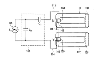
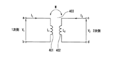
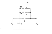
図1において、発光管111及び112は、ソーダライムガラスやホウ珪酸ガラス、石英などの光透過性の材料で成形した気密な環状の放電容器で構成されている。また、発光管111及び112の寸法は、既存の直管形の蛍光ランプや直管形を折り返した形状のコンパクト蛍光ランプと同様に、照明器具の配光設計の観点から、管外直径は15〜38mmが好ましく、その中でも、高周波点灯の直管蛍光ランプで最も普及率の高いT8管(25mm管)やT10管(32mm管)は、既存の器具の光学系をそのまま流用できることから有用である。また、管長(一本の放電管の全長)は、150mm〜600mmの放電管とすることが実用的であり、複数個並べることで、20Wの直管蛍光ランプの約600mm、40Wの直管蛍光ランプの約1200mmに相当する器具光学系を形成しやすい。また、ランプの消費電力については、既存の施設、屋外用の照明用として使用されている直管の蛍光ランプやコンパクト形の蛍光ランプと同程度で、20〜110Wが実用的である。また、発光管111及び112の内部には、水銀と、アルゴン、クリプトン、キセノンなどのうち一種類または複数種類の希ガスが封入され、放電容器壁面には蛍光体が塗布されている(図示しない)。
In FIG. 1,
誘導コイル102及び103は、リッツ線により形成され、トロイダル形状のフェライトコア104及び105の周囲に数回から数十回の巻数で巻かれている。また、全誘導コイルの合成インダクタのQ値(Q=ωL/R ω:角周波数、L:インダクタンス、R:等価抵抗)が、100〜250になるよう設計することが、発光管の始動性、点灯安定性の観点から望ましい。
The induction coils 102 and 103 are formed of litz wire, and are wound around the
フェライトコア104及び105は、環状の発光管111及び112の一部を覆うように挟み込まれている(トクマク方式)。この際、発光管の点灯始動時にかかる誘導コイルが励起する磁束でフェライトコアが磁束飽和されて、所要の磁束が得られず始動性能を損なわないために、また、製造上の嵌め込み面の接触不良などによる電気特性ばらつきを吸収するために、トロイダルコアの一部に樹脂部材などのスペーサーを挟み込み、磁気的なギャップを設けても良い。
The
誘導コイル導入線113及び114は、それぞれ一端が誘導コイル102または103の一端に接続され、他端が整合回路107に接続されている。また、誘導コイル導入線115は、両端が誘導コイル102及び103に接続されている。すなわち、誘導コイル102及び103は、誘導コイル導入線113〜115によって直列接続されている。
Each of the induction
整合回路107は、商用電源とインバータ回路とにより構成(図示しない)される高周波電源106と、誘導コイルとの間で、インピーダンス整合を行う回路である。通常、整合回路は、誘導コイルのインダクタとの共振現象を利用するため、キャパシタの組み合わせ、または、キャパシタとインダクタとの組み合わせにより構成される。図1では、最も簡易なキャパシタ2つによるL形の構成としているが、この限りでなく、誘導コイルのインダクタと狙いの駆動周波数(点灯周波数)で共振するよう定数の設計を行えばよい。
The
高周波電源106は、高周波電流を発生するものであり、高周波電源106から供給される高周波電流によって誘導高周波電磁場を発光管111及び112内に誘起して放電を発生させている。高周波電源106は、回路でのスイッチングロスや、使用しているコア材料を考慮すると、40kHz〜3MHz間の駆動周波数が望ましく、矩形波か正弦波を出力する。誘導コイル102及び103には、発光管の点灯始動時には1.5〜2.5kVのピーク・トゥ・ピークの電圧がかかるので、絶縁被覆を施した線材を使用しており、誘導コイル102と103は電源側から見ると互いに直列接続されている。
The high
トクマク方式の無電極放電灯を構成しているのは、前述のようにトクマク方式では光の取り出し効率が高く、また、その形状から、直管蛍光ランプを模し、2灯配列したランプ配光となるからである。また、複数の発光管を配設しているのは、一つの発光管で長尺の線光源を実現する場合と比して、前述の通り、複数に分割した短尺の発光管とする方が、放電プラズマのインピーダンスを小さくし、放電維持性能と効率を向上させることができるからである。このトクマク方式の無電極発光管を複数個、長手方向に配列すれば線光源を実現することができ、マトリクス状に配置すると薄い面光源を実現することができる。以下、この動作原理を説明する。 As described above, the Tokumak electrodeless discharge lamp is composed of a Tokumaku system with high light extraction efficiency, and the shape of the lamp distribution of two lamps that simulates a straight tube fluorescent lamp. Because it becomes. In addition, a plurality of arc tubes are arranged, as compared with the case where a long linear light source is realized with one arc tube, as described above, a short arc tube divided into a plurality is used. This is because the discharge plasma impedance can be reduced, and the discharge maintenance performance and efficiency can be improved. A linear light source can be realized by arranging a plurality of Tokumak type electrodeless arc tubes in the longitudinal direction, and a thin surface light source can be realized by arranging them in a matrix. Hereinafter, this operation principle will be described.
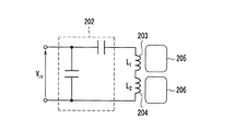
図2A〜図2Dは、図1の誘導コイル部分と発光管の部分等価回路図と発光管の模式図である。図2Aは始動点灯前の状態を示し、図2Bは一方の発光管において先に種火が点火した直後のE放電の状態を示し、図2Cは一方の発光管がH放電に移行した状態を示し、図2Dは両方の発光管が共にH放電に移行した状態を示している。図2A〜図2Dの順番で、発光管が点灯される様子を示している。 2A to 2D are a partial equivalent circuit diagram of the induction coil portion and arc tube of FIG. 1 and a schematic diagram of the arc tube. FIG. 2A shows the state before the start-up lighting, FIG. 2B shows the state of E discharge immediately after the ignition is ignited in one arc tube, and FIG. 2C shows the state in which one arc tube has shifted to H discharge. FIG. 2D shows a state in which both arc tubes have shifted to H discharge. FIG. 2A to FIG. 2D illustrate how the arc tube is turned on.
以上のように構成された無電極放電ランプについて、以下その動作を説明する。 The operation of the electrodeless discharge lamp configured as described above will be described below.
無電極放電灯は、商用電源からインバータにより変換された高周波電源を、図2Aに示す整合回路202のキャパシタと、誘導コイル203及び204との共振現象を利用して、大きな電圧及び電流を誘導コイル203及び204に供給している。電源投入後、複数個配設された発光管205及び206の内、最も始動し易いもの(図の例では発光管205)から順に、誘導高周波電磁場によって放電の種火が発生する。図2Bは、発光管205内において、種火発生により形成された容量結合プラズマ(E放電)の等価回路モデルを示している。
In the electrodeless discharge lamp, a high frequency power source converted from a commercial power source by an inverter is used to generate a large voltage and current by utilizing a resonance phenomenon between the capacitor of the
E放電では、図2Bに示すように、プラズマのキャパシタンス成分207のCplと抵抗成分208のRplとが、誘導コイル203に並列に接続された状態となり、新たに電流が流れるパスができる(厳密には、誘電体である放電容器によるキャパシタンス成分も存在する)。このため、誘導コイル203のL1を流れる電流は、誘導コイル側とプラズマ側の2つに分流され、誘導コイルL1の両端にかかる誘起電圧は、その分だけ低下することになる。つまり、インピーダンスが下がっているのである。
In the E discharge, as shown in FIG. 2B, C pl of the
また、種火すら発生していないもう一方の発光管206においては、電流のパスが誘導コイル204のL2以外に無く、誘導コイルL1と誘導コイルL2とが直列に接続されているため、誘導コイルL2の両端にかかる誘起電圧は低下しない。仮に並列接続であれば、誘導コイルL1の誘起電圧の低下に引きずられて誘導コイルL2の誘起電圧も低下するのと比較すると、それだけでも、放電開始が遅れた発光管206を点灯始動させるのに十分な電圧(電界)を与えることができるので、有利に作用することは容易に類推できる。
In addition, in the
さらに、図2Cでは、前述の先に放電を開始した発光管205で、E放電から、非常にプラズマ密度の高く発光効率の高い誘導結合プラズマ(H放電)へとモードジャンプしている様子の等価回路モデルを示している。
Further, in FIG. 2C, the equivalent of a mode jump from the E discharge to the inductively coupled plasma (H discharge) having a very high plasma density and a high luminous efficiency in the
なお、E放電からH放電に移行するメカニズム、要件に関しての諸説はあるが、明確にはされていないのが実情である。一般的には、発光管内に満たされたプラズマが、ドーナツ状のループを形成し、このプラズマにループ状の電流が流れる状態になって初めて、プラズマがトランスの2次側コイルの役割を果たすことができ、誘導結合に至ると考えられている。 Although there are various theories regarding the mechanism and requirements for shifting from E discharge to H discharge, the actual situation is not clear. Generally, the plasma filled in the arc tube forms a donut-shaped loop, and the plasma plays a role of the secondary coil of the transformer only when a loop-shaped current flows through the plasma. And is thought to lead to inductive coupling.
図2Cの場合、プラズマのインダクタンス成分309であるLp1と抵抗成分Rp1とにより構成され、誘導コイル203を1次側、プラズマのインダクタLp1を1ターンのループコイルとするトランスの2次側と見なせ、磁気的な結合(カップリング)によって発光管をH放電せしめる。このプラズマのインダクタLp1は、プラズマの形状によるものとプラズマ中の電子の運動の慣性によるものの合成であるが、通常、発光管の点灯周波数は数MHz以下とプラズマ周波数(数10GHz)と比して小さいため、電子の動きは点灯周波数に十分追随することができるため無視できる程度である。そのため、ほぼプラズマの形状によるものと考えてよい。
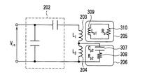
In the case of FIG. 2C, the secondary side of the transformer is composed of L p1 which is an
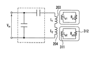
また、図2C中のCp2、Rp1はそれぞれ、遅れて放電の種火が発生した発光管206で発生した容量結合プラズマ(E放電)のキャパシタンス成分307、抵抗成分308を表す等価回路モデルである。これがモードジャンプし、誘導結合プラズマであるH放電に移行した時の状態を表しているのが、図2Dであり、それぞれ、Lp2、Rp2は、プラズマのインダクタンス成分311と抵抗成分312である。
Also, C p2 and R p1 in FIG. 2C are equivalent circuit models representing a
一般的に良く知られているように、H放電になると、誘導コイルの両端にかかる電圧は、放電開始前やE放電の状態に比して、約1/3〜1/5程度と大幅に低下する。これは、後述する1次側コイル(誘導コイルに相当)と2次側コイル(プラズマにより形成された放電電流ループに相当し、1ターンのコイルと見なす)との間の相互インダクタンスの影響によるものである。この相互インダクタンスにより、見かけ上、誘導コイルのインダクタンス成分が下がることで、図2Cに示される誘導コイル203のL1の両端に誘起される電圧が大きく低下する。
As is generally well known, when H discharge occurs, the voltage applied to both ends of the induction coil is significantly about 1/3 to 1/5 before the start of discharge and the state of E discharge. descend. This is due to the effect of mutual inductance between a primary coil (corresponding to an induction coil) and a secondary coil (corresponding to a discharge current loop formed by plasma and regarded as a one-turn coil) described later. It is. Due to this mutual inductance, the inductance component of the induction coil apparently decreases, so that the voltage induced at both ends of L 1 of the
本実施の形態では、誘導コイル203のL1と誘導コイル204のL2とが直列に接続されているため、オームの法則に従ってこのL1とL2の電圧の受け持ち(分圧)が、L1の電圧が低下した分だけL2の電圧を上昇せしめるのである。この結果、放電開始が遅れた方の発光管206では、放電開始(種火発生)からE放電、H放電へと放電のモードジャンプするに足る十分な電圧、誘導電界を得ることができるため、点灯始動が容易かつ確実なものとなる。
In the present embodiment, since L 1 of
なお、L1とL2が並列に接続されている場合は、先にH放電に移行した発光管側の誘導コイルL1の電圧低下に引きずられて、誘導コイルL2の電圧が下がるので、放電開始の遅れた発光管では、L2からE放電、H放電へとモードジャンプするに足る電圧、誘導電界が得られないため、何らかの別の手段を付与しなければ不点状態となるのは言うまでもない。 In addition, when L 1 and L 2 are connected in parallel, the voltage of the induction coil L 2 is lowered by being dragged by the voltage drop of the induction coil L 1 on the arc tube side that has shifted to H discharge first . In the arc tube with a delayed start of discharge, a voltage and an induced electric field sufficient for mode jump from L 2 to E discharge and H discharge cannot be obtained. Needless to say.
次に、このH放電に至った際の誘導コイルとプラズマとの相互インダクタンスの影響について述べる。 Next, the influence of mutual inductance between the induction coil and plasma when this H discharge is reached will be described.
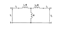
図3Aにはトランスの一般的な結合回路を示し、図3Bはその等価回路を示している。図3A及び図3Bにおいて、L1は1次側コイル401で、無電極放電灯装置では誘導コイルに相当する。L2は2次側のコイル402で、無電極放電灯装置では誘導結合放電により発光管内に形成されるプラズマのインダクタンス成分(1ターンのコイル)に相当し、主にプラズマの形状(プラズマ密度も含む)に依存する。Mは、1次側コイル401と2次側コイル402との間に作用する相互インダクタンス(Mには符号を含む)であり、1次側にV1の電圧を与えることで、2次側にV2の電圧を誘起している様子を示している。図3A及び図3Bから明らかなように、1次側コイル401の電圧V1は、2次側コイル402に流れる電流I2の影響を受ける。また、2次側コイルの電圧V2は、1次側コイルの電流I1の影響を受ける。
FIG. 3A shows a general coupling circuit of the transformer, and FIG. 3B shows an equivalent circuit thereof. 3A and FIG. 3B, L 1 is a
このような結合回路の電圧、電流の関係はそれぞれ複素電圧、複素電流を用いて表記すると下記数式1のようになる。
The relationship between the voltage and current of such a coupling circuit is expressed by the following
V1=jωL1*I1+jωM*I2
V2=jωL2*I2+jωM*I1
(V1、V2、I1、I2はいずれも複素電圧、電流であり、jは虚数、ωは角周波数) ・・・〔数式1〕
V 1 = jωL 1 * I 1 + jωM * I 2
V 2 = jωL 2 * I 2 + jωM * I 1
(V 1 , V 2 , I 1 , and I 2 are all complex voltage and current, j is an imaginary number, and ω is an angular frequency.) [Equation 1]
この際、Mの中には符号が含まれている(無電極放電の場合、H放電に至ると電圧が低下することから、ここではM<0となる)。また、Mは、下記数式2のように表され、結合係数kは、−1≦k≦1の値をとり、|k|が1に近いほど結合が高いことを示している。
At this time, a code is included in M (in the case of electrodeless discharge, the voltage decreases when the H discharge is reached, so here M <0). Further, M is expressed as in
M=k√(L1*L2) ・・・〔数式2〕 M = k√ (L 1 * L 2 ) (Equation 2)
このように、1次側の電圧V1は、相互インダクタンスMの大きさに比例して低下し、Mの大きさはL2(無電極放電灯ではプラズマのインダクタンス成分に相当)の平方根に比例、結合係数kに比例することから、結合率の高い無電極放電灯、すなわち、前述のトクマク方式によるものや、プラズマ密度が高くなる高効率な無電極放電灯ではH放電に移行することによる誘導コイルの電圧低下の度合いが大きくなるということである。さらに、整合回路のキャパシタと誘導コイルのインダクタによるLC共振周波数は、下記数式3として記述される。 Thus, the primary-side voltage V 1 decreases in proportion to the magnitude of the mutual inductance M, and the magnitude of M is proportional to the square root of L 2 (corresponding to an inductance component of plasma in an electrodeless discharge lamp). Since it is proportional to the coupling coefficient k, the electrodeless discharge lamp with a high coupling rate, that is, the above-described Tokumak method or the highly efficient electrodeless discharge lamp with a high plasma density is induced by shifting to H discharge. That is, the degree of voltage drop of the coil increases. Further, the LC resonance frequency by the capacitor of the matching circuit and the inductor of the induction coil is described as the following Equation 3.
F=1/(2π√(L*C)) ・・・〔数式3〕
(Fは共振周波数で、F=ω/2π)
F = 1 / (2π√ (L * C)) [Equation 3]
(F is the resonance frequency, F = ω / 2π)
数式3において、Lは複数個の配設された誘導コイルの合成インダクタンスで、Cは整合回路に含まれる全キャパシタの合成キャパシタンスである。 In Equation 3, L is a combined inductance of a plurality of induction coils, and C is a combined capacitance of all capacitors included in the matching circuit.
これがH放電移行後には、プラズマの形状と投入電力に依存して決まるプラズマのインダクタンス成分(こちらもトクマク方式が電流ループが大きくなるため圧倒的にインダクタンスは大きくなる)が加わることによりLからL’に推移し、共振周波数はFからF’に推移する。つまり、プラズマのインダクタンス成分が大きくなるほど共振周波数の推移が大きくなる。逆に、誘導コイルの合成インダクタンスが大きいほど、プラズマのインダクタンス成分による変動分が誘導コイルのインダクタンスに比して相対的に小さくなるため、共振周波数の推移は少なくなる。つまり、誘導コイルの直列接続の方が、誘導コイルの合成インダクタンスが大きくなるため、H放電移行前後での共振周波数との間のズレは小さくなる。 After this transition to H discharge, the inductance component of the plasma, which depends on the shape of the plasma and the input power (again, the inductance is overwhelmingly large due to the large current loop in the Tokumaku method), is added from L to L ′. The resonance frequency changes from F to F ′. In other words, the transition of the resonance frequency increases as the plasma inductance component increases. Conversely, the greater the combined inductance of the induction coil, the smaller the fluctuation due to the plasma inductance component is, compared to the inductance of the induction coil, so the transition of the resonance frequency is reduced. In other words, since the combined inductance of the induction coils is larger in the series connection of the induction coils, the deviation from the resonance frequency before and after the transition to the H discharge is smaller.
以上のことから、本発明の無電極放電灯装置の如く、それぞれ異なるループ状の発光管に配設された各誘導コイル同士の接続を直列接続とすることで得られる特徴を下記に記す。 From the above, the characteristics obtained by connecting the induction coils arranged in different looped arc tubes in series as in the electrodeless discharge lamp device of the present invention are described below.
まず、第一に、点灯始動を良好かつ確実にする行うことができる。すなわち、複数の発光管を多灯点灯する場合、先に放電を開始した発光管に配設した誘導コイルの誘起電圧の低下の影響で、点灯始動が遅れた発光管に配設した誘導コイルの誘起電圧が大きくなる。これにより、H放電に移行するのに十分な誘導電界を得ることができるためである。 First of all, it is possible to perform the lighting start well and reliably. In other words, when multiple lamps are lit, the induction coil disposed in the arc tube whose lighting start has been delayed due to the decrease in the induced voltage of the induction coil disposed in the arc tube that has started discharging earlier. The induced voltage increases. This is because an induction electric field sufficient to shift to H discharge can be obtained.
第二に、点灯始動性と効率の双方を両立することができる。すなわち、複数の誘導コイルを直列に接続するために、並列接続に比して、その合成インダクタンスは大きくなる(並列接続の方が合成インダクタンスは小さい)。そのため、相対的に、H放電プラズマへとモードジャンプすることにより発生するプラズマのインダクタンス成分の変動の影響が小さくなる。その結果、放電の開始前における共振周波数と、H放電移行後の共振周波数のズレが小さくなるため、並列接続の場合に比して、力率(インピーダンス整合の適正化)の低下度合いが小さい。点灯始動の前後で共振周波数のズレが大きいと、始動前の共振点と定常点灯時(H放電移行後)の共振点との双方の妥協点にて、インバータの駆動周波数を設計しなければならず、始動性も効率の両立が困難になってしまうことは言うまでもない。 Second, it is possible to achieve both lighting startability and efficiency. That is, since a plurality of induction coils are connected in series, the combined inductance is larger than that in parallel connection (the combined inductance is smaller in parallel connection). For this reason, the influence of fluctuation of the inductance component of the plasma generated by mode jumping to the H discharge plasma is relatively reduced. As a result, the difference between the resonance frequency before the start of discharge and the resonance frequency after the transition to H discharge is small, and the degree of decrease in the power factor (impedance matching) is small compared to the case of parallel connection. If the deviation of the resonance frequency is large before and after the start of lighting, the drive frequency of the inverter must be designed at a compromise between the resonance point before start and the resonance point during steady lighting (after transition to H discharge). Needless to say, it is difficult to achieve both startability and efficiency.
第三に、誘導コイルを直列接続することで、点灯回路中に流れる総電流量(電流量の総和)が、並列接続に比して大幅に小さく、高周波電源部での回路素子の消費電力を小さく抑えることができる。このため、点灯回路中での損失を低減できると同時に、点灯回路中から放射される電磁ノイズ(特に放射磁界)を低減させることができる。 Third, by connecting the induction coils in series, the total amount of current that flows in the lighting circuit (total amount of current) is significantly smaller than that in parallel connection, reducing the power consumption of the circuit elements in the high-frequency power supply section. It can be kept small. For this reason, the loss in the lighting circuit can be reduced, and at the same time, the electromagnetic noise (particularly the radiation magnetic field) radiated from the lighting circuit can be reduced.
無電極放電灯の形態の中で、比較的、1次側誘導コイルと2次側プラズマコイルとの間での電磁誘導の結合率が高く、効率が出やすい放電灯(たとえば、閉ループ状の発光管形状を有するトクマク方式の無電極放電灯)ほど、さらには、高出力用の投入電力が高い(プラズマ密度が高い)放電灯ほど、前記2つの特徴の優位性が顕著となる。 Among the forms of electrodeless discharge lamps, discharge lamps having a relatively high electromagnetic induction coupling ratio between the primary side induction coil and the secondary side plasma coil and being easy to obtain efficiency (for example, closed loop light emission) The superiority of the above two features becomes more pronounced as the tube-shaped electrodeless discharge lamp (Tumaku type electrodeless discharge lamp) and the discharge lamp with higher input power (high plasma density) for high output.
これにより、H放電の移行前後で、負荷(発光管および励起コイル)のインピーダンス変動が大きいトクマク方式の無電極放電灯を複数点灯させることができる。また、効率が良好で、光源の配列の仕方次第で線光源にも面光源にも展開可能な利便性、照明設計が容易なトクマク方式の複数の無電極放電灯を点灯させることができる。 Thereby, before and after the transition of the H discharge, it is possible to light a plurality of Tokumaku type electrodeless discharge lamps having a large impedance fluctuation of the load (the arc tube and the excitation coil). In addition, it is possible to turn on a plurality of Tokumaku type electrodeless discharge lamps that are efficient and have convenience that can be applied to both line light sources and surface light sources depending on how light sources are arranged, and lighting design is easy.
なお、本実施形態では、2個の発光管を配設した例を示しているが、3個以上の場合も同様の効果を得ることができる。 In the present embodiment, an example in which two arc tubes are arranged is shown, but the same effect can be obtained when there are three or more arc tubes.
また、発光管の形状は、カタカナの“ロ”の字形の場合を示したが、これに限定されるものでなく、アルファベットの“O”型(環状)や“H”型など放電プラズマの形状をループ型に形成せしめる放電容器の形態であっても良い。 In addition, although the arc tube has been shown with a katakana “b” shape, it is not limited to this, but the shape of the discharge plasma, such as the alphabet “O” type (annular) or “H” type. The discharge vessel may be formed in a loop shape.
また、整合回路107の構成は、本実施の形態ではキャパシタ2つを直並列に接続した最も簡易なL型の例を示したが、その構成に限定されるものではなく、いわゆるT型やπ型の回路構成でもよい。さらに、キャパシタやインダクタを複合組み合わせてもよい。また、本実施形態の整合回路107では、単一の共振系の構成としているが、各発光管に配設された誘導コイル毎に共振系(整合回路)を設けても良い。
The configuration of the
(実施の形態2)
次に、本発明の実施の形態2を、図4を参照して説明する。
(Embodiment 2)
Next, a second embodiment of the present invention will be described with reference to FIG.
図4において、無電極放電装置は、高周波電源501と、誘導コイルと共振させるための整合回路502と、2個の発光管503及び504と、それぞれの発光管に配されている誘導コイル505〜508とを備えている。
In FIG. 4, an electrodeless discharge apparatus includes a high-
発光管503には、誘導コイルの505と507が配設され、発光管504には誘導コイルの506と508が配設されている。全ての誘導コイル505〜508は、直列に接続され、誘導コイル505及び506の一端はそれぞれ整合回路502に接続されている。同一発光管上で誘導コイルを複数配設する際には、その誘導コイル同士の接続には、コイルの設置向きに注意が必要であり、誘導コイルにより発光管内に発生する誘導電界の向きが、管形状内のループに沿って同一方向になるように揃えなければならない(位相を合わせる)。誘導電界の向きが管形状内のループに沿って同一周方向でなければ、発生する誘導電界が互いに打ち消し合い、放電電流ループが形成されず、H放電に移行できないからである。
The
定常点灯のH放電に移行させるためには、発光管503及び504内をE放電によるプラズマで満たして、管内にループ状の電流パスを形成しなければならない。このループ状に形成されたプラズマの密度が高まり、このループに沿って放電電流が流れるようになると、E放電で形成された誘導コイルに近接する発光管内の一部のみで流れる電流パスよりも、ループ状に発光管内を一周する電流パスの方が主体へと移行する、つまり、これが、H放電への移行動作である。
In order to shift to the H discharge of steady lighting, the
本発明者らは、放電モードの移行(E放電からH放電)のメカニズムに関する実験検討、および、点灯始動時過渡状態における放電の発光部(プラズマ)高速カメラ撮影による画像解析の結果、以下の結論を見出すに至った。すなわち、E放電では、誘導コイルに近接した発光管の一部のみの放電であるから、これを、さらにプラズマの密度を高めて管内に拡散させ、かつ、プラズマは導体なので、プラズマ中に発生する誘導コイルによる誘導電界でプラズマ中の荷電粒子を管内ループ状に移動させる(つまり、放電電流ループを形成する)プロセスが滞りなく行われることが、H放電への移行を容易にすることを実験的に見出した。この理由から、E放電からH放電へと移行させるためには、発光管内の一部の誘導電界が部分的に極端に強いことではなく、管内全般に渡って幅広く、適度に強い誘導電界を形成することが、H放電の移行には大きな役割を果たすことが明らかになった。 As a result of an experimental study on the mechanism of the transition of the discharge mode (E discharge to H discharge) and image analysis by high-speed camera photography of the discharge light emitting part (plasma) in the transient state at the start of lighting, the following conclusions have been obtained. I came to find. That is, since the E discharge is a discharge of only a part of the arc tube adjacent to the induction coil, this is further diffused in the tube by increasing the density of the plasma, and since the plasma is a conductor, it is generated in the plasma. It is experimentally demonstrated that the process of moving charged particles in plasma in an in-tube loop shape (that is, forming a discharge current loop) by an induction electric field generated by an induction coil without delay is easy to shift to H discharge. I found it. For this reason, in order to shift from the E discharge to the H discharge, a part of the induced electric field in the arc tube is not partially extremely strong, but forms a moderately strong induced electric field that is wide throughout the tube. It has become clear that it plays a major role in the transition of H discharge.
誘導電界の強度は、誘導コイルから離れるほど、ビオ・サバールの法則に従って距離の2乗に反比例し低下する。そのために、管内で誘導コイルから最も離れた位置の誘導電界をいかに高めることができるかが、始動性(H放電へのモードジャンプ)を良好にするための重要な要件である。1つの発光管上において、誘導コイルから最も離れたところの発光管内部の部分までの距離、すなわち、図1における誘導コイル配設の例では誘導コイルと対向する側の発光管の端部108と、図4の誘導コイルの配設の例では対向する双方の誘導コイルからの距離が等しい発光管中央付近509とを比較すると、図4の場合は図1の場合の約半分(1/2)の距離になる。図4は1つの誘導コイルを2つの誘導コイルに分割して設置している構成である。たとえば、誘導コイルを等分割した時に誘導コイル両端に発生する誘起電圧は1/2になり、誘導コイル付近の発光管内部での誘導電界もおおよそ1/2となる(コイルと少し距離がある分、1/2より若干小さくなる)。距離の逆2乗に比例するので、発光管内部の誘導コイルから最も離れたところの位置509では、位置108に比べ距離が1/2になるので同一の誘導コイルであれば誘導電界は4倍となる。つまり、結果的に、誘導コイルの性能ファクターと距離のファクターを掛け合わせると、位置509では位置108の誘導電界の2倍となる。また、電磁気現象は重ね合わせが成立するので、図4のように誘導コイルが2個となると総計4倍の誘導電界強度となる。つまり、H放電へ移行するためにボトルネックとなっていた、誘導コイルからの最も遠方部の誘導電界を効果的に高めることができるため、点灯始動性(E放電からH放電へのモードジャンプ)を格段に向上させることができる。そのため、誘導コイルを複数個分割して、H放電の電流ループのパス上に配設することでさらに始動性が向上するのである。なお、図4に示す構成は、1つの発光管上に2つの誘導コイルを対向させて配設しているが、3以上に分割しても同様の効果が得られる。また、配設間隔が不均等であっても、同様の効果が得られる。
The strength of the induced electric field decreases as the distance from the induction coil increases in inverse proportion to the square of the distance according to Bio-Savart's law. Therefore, how to increase the induction electric field at the position farthest from the induction coil in the tube is an important requirement for good startability (mode jump to H discharge). The distance from the induction coil to the portion inside the arc tube that is farthest from the induction coil, that is, the
(実施の形態3)
本発明の第3の実施形態を図5を参照して説明する。
(Embodiment 3)
A third embodiment of the present invention will be described with reference to FIG.
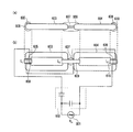
図5(a)は無電極放電灯装置の側面図で、図5(b)は平面図である。図5の構成において、同一発光管上で配設された複数の誘導コイルのうち、一つの誘導コイル607を、2つの発光管603及び604を隣接して配設することで、共通化(一体化)している構成となっている。すなわち、図5に示すように、1つのフェライトコア609で保持された2個の発光管603及び604の間に、誘導コイル607が巻回されている。また、発光管603において、フェライトコア609に対向する位置に、誘電コイル605が巻回されているフェライトコア608が配されている。また、発光管604において、フェライトコア609に対向する位置に、誘電コイル606が巻回されているフェライトコア610が配されている。誘電コイル605、607、606は直列接続され、両端は整合回路602に接続されている。
Fig.5 (a) is a side view of an electrodeless discharge lamp apparatus, FIG.5 (b) is a top view. In the configuration of FIG. 5, among a plurality of induction coils arranged on the same arc tube, one
誘導コイル605、606、607を、図5に示すように直列接続することで、誘導コイルによって発光管内に発生する誘導電界の向きが、発光管603及び604のループに沿って同一方向に揃うよう位相を合わせることができる。
By connecting the induction coils 605, 606, and 607 in series as shown in FIG. 5, the direction of the induction electric field generated in the arc tube by the induction coil is aligned in the same direction along the loop of the
このような構成の無電極放電灯装置においては、点灯の原理は前述の実施形態2(図4参照)と同じであるが、図4の構成に比べ部品点数を削減できるため、製造コストを削減することができる。また、装置のコンパクト化が図れる。 In the electrodeless discharge lamp device having such a configuration, the principle of lighting is the same as that of the second embodiment (see FIG. 4), but the number of parts can be reduced compared to the configuration of FIG. can do. In addition, the apparatus can be made compact.
なお、本実施形態では、2個の発光管603及び604を一例に挙げて説明しているが、3個以上であってもよい。その場合は、フェライトコア609のように2つの発光管を保持可能な構成のフェライトコアで、複数の発光管を数珠繋ぎにして保持させることで、上記と同様の効果が得られる。
In the present embodiment, the two
(実施の形態4)
本発明の第4の実施形態を図6を参照して説明する。
(Embodiment 4)
A fourth embodiment of the present invention will be described with reference to FIG.
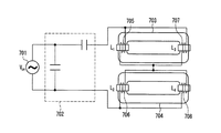
図6は、高周波電源701は、整合回路702を介して誘導コイル705〜708に接続されている。発光管703に配設されている誘導コイル705と誘導コイル707とは並列に接続され、誘導コイル705及び707により発生する誘導電界の向きが合わせられている。また、発光管704に配設されている誘導コイル706と誘導コイル708とは並列に接続されている。2つの発光管703及び704を跨って配設された誘導コイル同士の接続は、高周波電源701側から見て直列接続とする。
In FIG. 6, the high
図6に示す構成とすることで、先にH放電に移行した発光管に配設されている誘導コイルの両端にかかる誘起電圧が低下すると、他方の発光管(放電開始が遅れた方の発光管)に配設されている誘導コイルに誘起される電圧は、電源側から見て直列接続であるため、その分圧の関係から上昇する。つまり、放電開始からH放電移行までを容易にするという本来の特徴を有している。 With the configuration shown in FIG. 6, when the induced voltage applied to both ends of the induction coil disposed in the arc tube previously shifted to the H discharge decreases, the other arc tube (the light emission whose start of discharge is delayed). Since the voltage induced in the induction coil disposed in the tube is a series connection as viewed from the power supply side, the voltage rises due to the partial pressure relationship. In other words, it has the original characteristic of facilitating from the start of discharge to transition to H discharge.
同一の発光管上で複数個の誘導コイルを配設させているのは、本発明の実施形態2で述べた理由と同様に、誘導電界の強度を高め、E放電時の初期のプラズマの分布を広げるためである。 The reason why a plurality of induction coils are arranged on the same arc tube is to increase the strength of the induction electric field and to distribute the initial plasma during E discharge, for the same reason as described in the second embodiment of the present invention. It is to spread.
また、同一の発光管上で配設された誘導コイル同士の接続を並列にすることで、誘導コイル705と誘導コイル707、または、誘導コイル706と誘導コイル708の電圧、誘導コイルにより生じる発光管内の誘導電界が対称となるため、放電中のプラズマに作用する影響が双方で均等となる。結果、同一発光管上での発光輝度が均斉化され、効率を高めることができる。
In addition, by connecting the induction coils arranged on the same arc tube in parallel, the voltage of the
以上のように本実施の形態によれば、誘導コイルを電源側から見て並列接続にした場合に比して、発光管の点灯始動前と、H放電移行後の共振周波数の変化が小さくて済むのは前述の通りである。しかしながら、この場合も、インバータの駆動周波数と共振周波数のズレにより、共振系(整合回路含む)の負荷側入力の力率が低下、電流、電圧の上昇することで回路効率がわずかに低下することは避けられない。この点灯前後でのインバータ駆動周波数と共振周波数のズレを改善し、効率の低下を抑制する本願発明の実施形態について、以下、図7A〜図8Bを参照して説明する。 As described above, according to the present embodiment, the change in the resonance frequency before the start of lighting of the arc tube and after the transition to the H discharge is small as compared with the case where the induction coil is connected in parallel when viewed from the power source side. As described above, it is completed. However, in this case as well, the power efficiency of the load side input of the resonance system (including the matching circuit) decreases due to the difference between the drive frequency of the inverter and the resonance frequency, and the circuit efficiency slightly decreases due to the increase in current and voltage. Is inevitable. An embodiment of the present invention that improves the deviation between the inverter drive frequency and the resonance frequency before and after lighting and suppresses the decrease in efficiency will be described below with reference to FIGS. 7A to 8B.
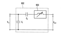
図7Aは、本発明の実施形態の整合回路部の一例を示すものである。整合回路部への入力端子801から整合回路802を経て、誘導コイル及び発光管側への出力端子806に接続されている。整合回路802は、基本構成をキャパシタ803とキャパシタ804とで構成され、キャパシタ804に対して並列に可変キャパシタ805を接続している。
FIG. 7A shows an example of the matching circuit unit according to the embodiment of the present invention. The
図7Aにおいて、発光管の放電モードがH放電に移行すると、放電プラズマのインダクタンス成分により、誘導コイルとプラズマのインダクタンス成分の負荷側の合成インダクタンスが低下する。そのため、前記数式3に示すように、インダクタンス成分が小さくなることで、共振周波数は高い方へ推移する。H放電の前後で、この共振周波数とインバータの駆動周波数を一致させるためには、このインダクタンス成分の低下分を整合回路部でのキャパシタ成分を増加させることで補い、共振系回路での共振周波数を一定にすることができる。つまり、整合回路部802に含まれる可変キャパシタ805は、この補正を行うためのものであり、H放電への移行前後で可変キャパシタ805により共振周波数を、インバータの駆動周波数を合わせることができる。段階的に切り替えるキャパシタの容量(定数)は、予め点灯させる発光管のプラズマによるインダクタンス成分の変化分に合わせて設計しておけばよい。
In FIG. 7A, when the discharge mode of the arc tube shifts to H discharge, the combined inductance on the load side of the induction coil and the inductance component of the plasma decreases due to the inductance component of the discharge plasma. Therefore, as shown in the mathematical formula 3, the resonance frequency shifts higher as the inductance component becomes smaller. In order to make this resonance frequency and the drive frequency of the inverter coincide before and after the H discharge, the decrease in the inductance component is compensated by increasing the capacitor component in the matching circuit section, and the resonance frequency in the resonance circuit is increased. Can be constant. That is, the
可変キャパシタ805のより具体的な構成を図7Bに示す。図7Bに示すように、図7Aの可変キャパシタ805を、図7Bの可変キャパシタ部807に代えて実現できる。可変キャパシタ部807は、互いに容量が異なるキャパシタC1及びC2を並列接続し、キャパシタC1はスイッチSW1でON/OFF制御され、キャパシタC2はスイッチSW2でON/OFF制御される。
A more specific configuration of the
複数点灯する際の各発光管が順次始動点灯する際、放電プラズマにより形成されるインダクタンス成分は、発光管の形状(プラズマの形状)と投入電力(定格消費電力)によって決まり、放電灯の仕様が決まれば自ずと確定する。そのため、発光管がH放電に移行する度に、点灯状態を検知して、順次、可変キャパシタ807に含まれるスイッチSW1及びSW2を切り替えて、可変キャパシタ807のキャパシタンスを決定し、整合回路部802における共振周波数をインバータの駆動周波数に合わせ込む。
When each arc tube is turned on in sequence, the inductance component formed by the discharge plasma is determined by the arc tube shape (plasma shape) and input power (rated power consumption). If it is decided, it will be decided by itself. Therefore, each time the arc tube shifts to H discharge, the lighting state is detected, the switches SW1 and SW2 included in the
点灯状態の検出方法は、発光管がH放電に切り替わると、その発光管に配設した誘導コイルの電圧、電流が大きく低下するため、これを検出しても良いし、発光管がH放電になると極端に光出力が増えるため、これをフォトダイオードなどの光検出素子で検知しても良い。また、発光管や誘導コイルの発熱量(温度)を検知するか、あらかじめ一定の時間が経過すると回路を切り替えるためのタイマー素子で構成しても良い。 When the arc tube is switched to H discharge, the voltage and current of the induction coil disposed in the arc tube are greatly reduced. This may be detected, or the arc tube is switched to H discharge. Then, the light output increases extremely, and this may be detected by a light detection element such as a photodiode. Further, it may be configured by a timer element for detecting the amount of heat (temperature) of the arc tube or the induction coil or switching the circuit when a certain time elapses in advance.
切り替え用のスイッチング素子は、前記検出した信号をトリガーとして切り替えるリレー回路や、PTC(温度が上昇すると抵抗が増加する)やNTC(温度が上昇すると抵抗が減少する)に代表されるスイッチング用のサーミスタ素子により構成しても良い。 The switching element for switching includes a relay circuit that switches using the detected signal as a trigger, a switching thermistor represented by PTC (resistance increases as temperature rises) and NTC (resistance decreases as temperature rises). You may comprise by an element.
また、図7Aに示すように、最も簡易な例としてキャパシタを直並列に接続したL型の整合回路の1つのキャパシタ804に並列に可変キャパシタを接続しているが、この限りでなく、キャパシタ803やキャパシタ804に直列、または、並列に接続することで整合回路部のキャパシタ成分を可変にする構成であれば良い。ただし、直列に挿入する場合と並列に挿入する場合では、H放電移行前後でのスイッチの切り替え状態が逆になり、いずれの場合も、整合回路部でのキャパシタ成分を増加させるように切り替えなければならない。
Further, as shown in FIG. 7A, as the simplest example, a variable capacitor is connected in parallel to one
次に、図8Aは、図7Aの可変キャパシタ805の役割を可変インダクタ903で代用した構成である。この構成は、発光管のH放電移行前後で変化する負荷側のインダクタンス成分を、整合回路に含めた可変インダクタ903で補うものであり、キャパシタC2に直列接続されている。これにより、インバータの駆動周波数と、整合回路および誘導コイル、発光管(プラズマ)により構成される共振系回路の共振周波数とを合わせることができる。
Next, FIG. 8A shows a configuration in which the role of the
図8Bは、図8Aの可変インダクタ903をより具体化したもので、切り替えのための点灯状態検知手段や、切り替えスイッチの構成は図7Bの構成と同様である。可変インダクタ905は、スイッチSW3〜SW6と、互いにインダクタンスが異なるインダクタl1及びl2とから構成されている。点灯状態検知手段の検知結果に基づいて、SW3〜SW6が切り替えられて、可変インダクタ905におけるインダクタンスを決定し、整合回路部の共振周波数を切り替えている。具体的には、スイッチSW3とSW6とをONにしてインダクタl1を導通状態にする第1の状態と、スイッチSW4とSW5とをONにしてインダクタl2を導通状態にする第2の状態とを有している。
FIG. 8B is a more specific example of the
また、以上の構成は、整合回路、誘導コイル、発光管を含めた負荷側の共振周波数を調整する方式であるが、このような構成に限らず、発光管の点灯状態を検知する手段により、インバータ回路(高周波電源)の駆動周波数を決定する共振回路へフィードバックする機能を備え、インバータ回路の駆動周波数を負荷側の共振周波数の変化に追従させるよう構成しても良い。その場合は、駆動周波数を、段階的または連続的に上昇させるよう制御する周波数制御部を備えることが好ましい。 Further, the above configuration is a method of adjusting the resonance frequency on the load side including the matching circuit, the induction coil, and the arc tube, but not limited to such a configuration, by means for detecting the lighting state of the arc tube, A function of feeding back to the resonance circuit that determines the drive frequency of the inverter circuit (high frequency power supply) may be provided, and the drive frequency of the inverter circuit may be made to follow the change in the resonance frequency on the load side. In that case, it is preferable to provide a frequency control unit that controls the drive frequency to increase stepwise or continuously.
この結果、点灯始動の前後で、整合回路および誘導コイル、プラズマのインダクタンス成分により構成される共振系の共振周波数と、インバータの駆動周波数とを、適時合わせることができるため、点灯始動の前後で共振回路での発振電圧、発振電流、力率を低下させること無く、容易に点灯を開始することができ、かつ、定常点灯のH放電移行後も、共振回路での力率を低下させることがないため、点灯回路の効率を高めることができる。 As a result, the resonance frequency of the resonance system composed of the matching circuit, induction coil, and plasma inductance component and the inverter drive frequency can be adjusted in time before and after the start of lighting. Lighting can be started easily without lowering the oscillation voltage, oscillation current, and power factor in the circuit, and the power factor in the resonance circuit will not be lowered even after transition to the H discharge of steady lighting. Therefore, the efficiency of the lighting circuit can be increased.
なお、本発明の実施形態では、多灯点灯として2個の発光管の場合を示したが、これに限定されるものでなく、誘導コイルの配設個数、位置が異なっても同様の効果を得ることができる。 In the embodiment of the present invention, the case of two arc tubes as multi-lamp lighting is shown. However, the present invention is not limited to this, and the same effect can be obtained even if the number and position of induction coils are different. Obtainable.
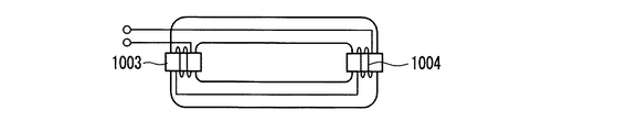
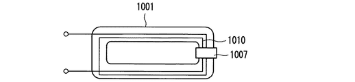
また、誘導コイルの巻き方は、本実施形態では、トロイダルコアに巻きつける構成としているが、これに限定されるものでなく、図9A〜図9Fに示されるように、トロイダルコアを搭載した誘導コイル1002の一部を、ループ状の発光管1001の壁面に沿わせた構成であってもよい。なお、図9Aは、誘導コイル1002を、発光管1001において整合回路から遠い側の端部に配した例である。図9Bは、発光管1001における対向する端部に、それぞれ誘導コイル1003及び1004を配した例であり、誘導コイル1003と1004とは直列接続されている。図9Cは、図9Bと同様の配置で、誘導コイル1003と1004とが並列接続されている例である。図9Dは、誘導コイル1010を、発光管1001に沿わせてループ状に巻き上げて配置させた例であり、端部がマグネット1007で固定されている。図9Eは、発光管1001の両端部において誘導コイル1010がマグネット1007及び1008で固定されている例である。図9Fは、発光管1001に沿わせてループ状に巻き上げて配置させた例であり、誘導コイル1010はマグネティックコアで固定されていない。
Further, in the present embodiment, the induction coil is wound around the toroidal core. However, the present invention is not limited to this, and as shown in FIGS. 9A to 9F, an induction equipped with a toroidal core is mounted. A configuration in which a part of the
放電容器の仕様も前記実施例のみに限定されるものでなく、アルゴン、クリプトンの混合ガスのみでなく他の希ガス(ネオン、アルゴン、クリプトン、キセノンなど)の単体または混合ガスでもよい。また、水銀の代わりに他の金属蒸気を用いても良いし、希ガスのみを使用しても同様の効果を得ることができる。 The specification of the discharge vessel is not limited to the above embodiment, and may be a single gas or a mixed gas of not only a mixed gas of argon and krypton but also other rare gases (neon, argon, krypton, xenon, etc.). Further, other metal vapor may be used instead of mercury, and the same effect can be obtained even when only a rare gas is used.
本発明の無電極放電ランプは、製造上容易で低コストな手段でランプの放電始動性を改善することができるので、一般施設、屋内外用照明等として有用である。 Since the electrodeless discharge lamp of the present invention can improve the discharge startability of the lamp by means that are easy to manufacture and low-cost, it is useful for general facilities, indoor / outdoor lighting, and the like.
102、103 誘導コイル
104、105 フェライトコア
106 高周波電源
107 整合回路部
111、112 放電容器(発光管)
501 高周波電源
502 整合回路部
503、504 発光管
505、506,507,508 誘導コイル
102, 103
501 High-
Claims (10)
前記放電容器の内部の放電空間に誘導高周波電磁場を誘起し、前記封入物を放電させるように前記各放電容器に少なくとも1個配設された誘導コイルと、
前記誘導コイルに高周波電力を供給するための高周波電源と、
前記誘導コイルと前記高周波電源との間でインピーダンス整合を行う共振回路を備えた整合部と、を備えた無電極放電灯点灯装置であって、
前記誘導コイルは、それぞれ異なる放電容器に配設された各誘導コイル同士が、前記高周波電源側から見て直列接続されていることを特徴とする無電極放電灯装置。 A plurality of discharge vessels, which are made of a light-transmitting material and in which an enclosure made of at least a metal vapor and a rare gas is enclosed;
An induction coil disposed in each discharge vessel so as to induce an induction high-frequency electromagnetic field in a discharge space inside the discharge vessel and discharge the inclusion;
A high frequency power source for supplying high frequency power to the induction coil;
A matching unit including a resonance circuit that performs impedance matching between the induction coil and the high-frequency power source, and an electrodeless discharge lamp lighting device comprising:
The induction coil is an electrodeless discharge lamp device in which induction coils arranged in different discharge vessels are connected in series as viewed from the high frequency power supply side.
前記一つの放電容器に配設されている複数個の誘導コイル同士が、前記電源側から見て直列接続されている請求項1記載の無電極放電灯装置。 An electrodeless discharge lamp lighting device in which a plurality of induction coils are arranged in one discharge vessel,
The electrodeless discharge lamp device according to claim 1, wherein a plurality of induction coils arranged in the one discharge vessel are connected in series as viewed from the power source side.
前記複数の放電容器の間には、一つの誘導コイルが配され、
前記複数の放電容器は、前記一つの誘導コイルによって点灯制御される請求項1記載の無電極放電灯装置。 The plurality of discharge vessels are disposed adjacent to each other;
One induction coil is arranged between the plurality of discharge vessels,
The electrodeless discharge lamp device according to claim 1, wherein lighting of the plurality of discharge vessels is controlled by the one induction coil.
各放電容器において、配設されている複数個の誘導コイル同士を、前記高周波電源側から見てそれぞれ並列接続され、
前記各放電容器間の誘導コイル同士が直列接続されている請求項1記載の無電極放電灯装置。 A plurality of induction coils are respectively disposed in the plurality of discharge vessels,
In each discharge vessel, a plurality of arranged induction coils are connected in parallel with each other when viewed from the high-frequency power source side,
The electrodeless discharge lamp device according to claim 1, wherein the induction coils between the discharge vessels are connected in series.
前記放電容器の点灯始動の状態を検出する点灯検出部とを備え、
前記切換部は、前記点灯検出部の検出結果に基づいて、段階的に前記整合部のキャパシタの定数を切り替える請求項1から5のいずれかに記載の無電極放電灯装置。 In accordance with the lighting start-up state of the plurality of discharge containers, a switching unit that switches the constant of the capacitor of the matching unit,
A lighting detection unit for detecting a lighting start state of the discharge vessel,
The electrodeless discharge lamp device according to any one of claims 1 to 5, wherein the switching unit switches a constant of the capacitor of the matching unit in a stepwise manner based on a detection result of the lighting detection unit.
前記複数の放電容器の点灯始動時の状態に合わせ、前記整合部のインダクタの定数を切り替える切換部と、
前記放電容器の点灯始動の状態を検出する点灯検出部とを備え、
前記切換部は、段階的に前記整合部のインダクタの定数を切り替える請求項1から5のいずれかに記載の無電極放電灯装置。 The matching portion includes at least one inductor.
In accordance with the lighting start state of the plurality of discharge containers, a switching unit that switches the constant of the inductor of the matching unit,
A lighting detection unit for detecting a lighting start state of the discharge vessel,
The electrodeless discharge lamp device according to claim 1, wherein the switching unit switches the constant of the inductor of the matching unit in a stepwise manner.
前記放電容器の点灯始動の状態を検出する点灯検出部とを備え、
前記周波数制御部は、前記点灯検出部の検出結果に基づいて、前記駆動周波数を段階的または連続的に上昇させるよう制御する請求項1から5のいずれかに記載の無電極放電灯装置。 In accordance with the lighting start state of the plurality of discharge containers, a frequency control unit that changes the driving frequency of the high-frequency power source,
A lighting detection unit for detecting a lighting start state of the discharge vessel,
The electrodeless discharge lamp device according to any one of claims 1 to 5, wherein the frequency control unit controls the drive frequency to increase stepwise or continuously based on a detection result of the lighting detection unit.
各放電容器に配設された誘導コイルの電気特性であるコイルに流れる電流、コイルの両端にかかる電圧、もしくは、電源投入後の経過時間、または、前記放電容器の点灯による発熱や光、に基づき検知する請求項6から8のいずれかに記載の無電極放電灯装置。 The lighting detection unit is a lighting start state of the discharge vessel,
Based on the current flowing through the coil, which is the electrical characteristic of the induction coil disposed in each discharge vessel, the voltage applied to both ends of the coil, the elapsed time after turning on the power, or the heat generation and light due to lighting of the discharge vessel The electrodeless discharge lamp device according to any one of claims 6 to 8, which is detected.
A lighting fixture using the electrical assembly according to any one of claims 1 to 9.
Priority Applications (1)
| Application Number | Priority Date | Filing Date | Title |
|---|---|---|---|
| JP2006091653A JP2007265902A (en) | 2006-03-29 | 2006-03-29 | Electrodeless discharge lamp and luminaire using it |
Applications Claiming Priority (1)
| Application Number | Priority Date | Filing Date | Title |
|---|---|---|---|
| JP2006091653A JP2007265902A (en) | 2006-03-29 | 2006-03-29 | Electrodeless discharge lamp and luminaire using it |
Publications (1)
| Publication Number | Publication Date |
|---|---|
| JP2007265902A true JP2007265902A (en) | 2007-10-11 |
Family
ID=38638683
Family Applications (1)
| Application Number | Title | Priority Date | Filing Date |
|---|---|---|---|
| JP2006091653A Ceased JP2007265902A (en) | 2006-03-29 | 2006-03-29 | Electrodeless discharge lamp and luminaire using it |
Country Status (1)
| Country | Link |
|---|---|
| JP (1) | JP2007265902A (en) |
Cited By (2)
| Publication number | Priority date | Publication date | Assignee | Title |
|---|---|---|---|---|
| JP2009110692A (en) * | 2007-10-26 | 2009-05-21 | Panasonic Electric Works Co Ltd | Lighting fixture equipped with electrodeless discharge lamp |
| CN114033985A (en) * | 2021-11-23 | 2022-02-11 | 浙江华岭医疗有限公司 | Myopia prevention desk lamp |
Citations (5)
| Publication number | Priority date | Publication date | Assignee | Title |
|---|---|---|---|---|
| JPH08236285A (en) * | 1995-02-28 | 1996-09-13 | Matsushita Electric Works Ltd | Lighting device for electrodeless discharge lamp |
| JPH08273854A (en) * | 1995-03-31 | 1996-10-18 | Toshiba Lighting & Technol Corp | Electric power supply circuit, electrodeless discharge lamp lighting device, lighting system |
| JPH10208894A (en) * | 1997-01-28 | 1998-08-07 | Matsushita Electric Works Ltd | Electrodeless discharge lamp lighting device |
| JP2001093685A (en) * | 1999-09-27 | 2001-04-06 | Matsushita Electric Works Ltd | Electrodeless discharge lamp lighting device |
| JP2001522524A (en) * | 1998-02-10 | 2001-11-13 | パテント−トロイハント−ゲゼルシャフト フュア エレクトリッシェ グリューランペン ミット ベシュレンクテル ハフツング | Lighting circuit device for at least one electrodeless discharge lamp |
-
2006
- 2006-03-29 JP JP2006091653A patent/JP2007265902A/en not_active Ceased
Patent Citations (5)
| Publication number | Priority date | Publication date | Assignee | Title |
|---|---|---|---|---|
| JPH08236285A (en) * | 1995-02-28 | 1996-09-13 | Matsushita Electric Works Ltd | Lighting device for electrodeless discharge lamp |
| JPH08273854A (en) * | 1995-03-31 | 1996-10-18 | Toshiba Lighting & Technol Corp | Electric power supply circuit, electrodeless discharge lamp lighting device, lighting system |
| JPH10208894A (en) * | 1997-01-28 | 1998-08-07 | Matsushita Electric Works Ltd | Electrodeless discharge lamp lighting device |
| JP2001522524A (en) * | 1998-02-10 | 2001-11-13 | パテント−トロイハント−ゲゼルシャフト フュア エレクトリッシェ グリューランペン ミット ベシュレンクテル ハフツング | Lighting circuit device for at least one electrodeless discharge lamp |
| JP2001093685A (en) * | 1999-09-27 | 2001-04-06 | Matsushita Electric Works Ltd | Electrodeless discharge lamp lighting device |
Cited By (3)
| Publication number | Priority date | Publication date | Assignee | Title |
|---|---|---|---|---|
| JP2009110692A (en) * | 2007-10-26 | 2009-05-21 | Panasonic Electric Works Co Ltd | Lighting fixture equipped with electrodeless discharge lamp |
| CN114033985A (en) * | 2021-11-23 | 2022-02-11 | 浙江华岭医疗有限公司 | Myopia prevention desk lamp |
| CN114033985B (en) * | 2021-11-23 | 2023-11-21 | 浙江华岭医疗有限公司 | Myopia prevention desk lamp |
Similar Documents
| Publication | Publication Date | Title |
|---|---|---|
| US9911589B2 (en) | Induction RF fluorescent lamp with processor-based external dimmer load control | |
| US10529551B2 (en) | Fast start fluorescent light bulb | |
| US5349271A (en) | Electrodeless discharge lamp with spiral induction coil | |
| US9524861B2 (en) | Fast start RF induction lamp | |
| US9305765B2 (en) | High frequency induction lighting | |
| US20140145607A1 (en) | Dimmable high frequency induction rf fluorescent lamp | |
| US20140320009A1 (en) | Processor-based dimmable induction rf fluorescent lamp | |
| US20140320008A1 (en) | Processor-based fast start induction rf fluorescent lamp | |
| US7800289B2 (en) | Electrodeless gas discharge lamp | |
| US20140145601A1 (en) | Dimmable induction rf fluorescent lamp | |
| US20140145600A1 (en) | High frequency induction rf fluorescent lamp with reduced electromagnetic interference | |
| EP2923373A1 (en) | Induction rf fluorescent lamp | |
| US20140145608A1 (en) | Fast start high frequency induction rf fluorescent lamp | |
| US20140145606A1 (en) | High frequency induction rf fluorescent lamp | |
| US20140145598A1 (en) | High frequency induction rf fluorescent lamp with burst-mode dimming | |
| US20140145604A1 (en) | Induction rf fluorescent lamp | |
| US20140145605A1 (en) | High frequency induction rf fluorescent lamp with reduced electromagnetic interference | |
| US20140145603A1 (en) | Induction rf fluorescent lamp with reduced electromagnetic interference | |
| US20140145602A1 (en) | Induction rf fluorescent lamp with burst-mode dimming | |
| US20140145597A1 (en) | Processor-based induction rf fluorescent lamp | |
| US10418233B2 (en) | Burst-mode for low power operation of RF fluorescent lamps | |
| JP2007265902A (en) | Electrodeless discharge lamp and luminaire using it | |
| WO2011032592A1 (en) | Low-pressure discharge lamp | |
| JPS6013264B2 (en) | fluorescent light | |
| JP4943726B2 (en) | Electrodeless discharge lamp device, electrodeless discharge lamp lighting fixture |
Legal Events
| Date | Code | Title | Description |
|---|---|---|---|
| A621 | Written request for application examination |
Free format text: JAPANESE INTERMEDIATE CODE: A621 Effective date: 20090216 |
|
| A711 | Notification of change in applicant |
Free format text: JAPANESE INTERMEDIATE CODE: A711 Effective date: 20100305 |
|
| A977 | Report on retrieval |
Free format text: JAPANESE INTERMEDIATE CODE: A971007 Effective date: 20110518 |
|
| A131 | Notification of reasons for refusal |
Free format text: JAPANESE INTERMEDIATE CODE: A131 Effective date: 20110524 |
|
| A521 | Written amendment |
Free format text: JAPANESE INTERMEDIATE CODE: A523 Effective date: 20110720 |
|
| A01 | Written decision to grant a patent or to grant a registration (utility model) |
Free format text: JAPANESE INTERMEDIATE CODE: A01 Effective date: 20120110 |
|
| A711 | Notification of change in applicant |
Free format text: JAPANESE INTERMEDIATE CODE: A712 Effective date: 20120111 |
|
| A045 | Written measure of dismissal of application |
Free format text: JAPANESE INTERMEDIATE CODE: A045 Effective date: 20120731 |