JP2007257581A - Failure analysis device - Google Patents
Failure analysis device Download PDFInfo
- Publication number
- JP2007257581A JP2007257581A JP2006084648A JP2006084648A JP2007257581A JP 2007257581 A JP2007257581 A JP 2007257581A JP 2006084648 A JP2006084648 A JP 2006084648A JP 2006084648 A JP2006084648 A JP 2006084648A JP 2007257581 A JP2007257581 A JP 2007257581A
- Authority
- JP
- Japan
- Prior art keywords
- failure
- faulty
- database
- failed
- network
- Prior art date
- Legal status (The legal status is an assumption and is not a legal conclusion. Google has not performed a legal analysis and makes no representation as to the accuracy of the status listed.)
- Pending
Links
Images


Abstract
Description
本発明は、プラントを監視制御する演算処理装置等の装置の故障を解析する故障解析装置に関する。 The present invention relates to a failure analysis device that analyzes a failure of a device such as an arithmetic processing device that monitors and controls a plant.
例えば、プラントを制御する制御装置はコンピュータをはじめとする演算処理装置で構成され、高い信頼性が要求される。そこで、制御装置自体に自己診断機能を設け、周期的に診断を行い、この診断結果をメモリへエラーログとして記憶するようにしている。そして、エラーログに基づいて故障解析をし故障の復旧処理を行い、制御装置の健全性を維持するようにしている。 For example, a control device for controlling a plant is constituted by a processing unit such as a computer, and high reliability is required. Therefore, a self-diagnosis function is provided in the control device itself, and diagnosis is performed periodically, and the diagnosis result is stored in the memory as an error log. Then, failure analysis is performed based on the error log, failure recovery processing is performed, and the soundness of the control device is maintained.
一般に、制御装置は複数の基板から構成され、エラーを発生する対象の機能が複数の基板に跨がって分散されることがあり、また、基板間の故障もある。従って、エラーが発生した場合には、エラーに関連する複数の基板を順次交換したり、基板の接続部の絞り込みを行う必要があるので、故障復旧までに多大の手間と時間を要する。 In general, the control device is composed of a plurality of substrates, and the function of the target for generating an error may be distributed across the plurality of substrates, and there is also a failure between the substrates. Therefore, when an error occurs, it is necessary to sequentially replace a plurality of substrates related to the error or to narrow down the connection portions of the substrates, so it takes a lot of time and effort to recover from the failure.
コントローラの故障解析装置として、故障部所を絞って復旧を早期に、かつ作業員の負担も軽減できるようにしたものがある(例えば、特許文献1参照)。この故障解析装置はシーケンスコントローラ内に内蔵され、故障解析装置はエラーログ解析手段及び故障データベースを有し、メモリにはエラーログが登録されている。そして、エラーログ解析手段は、エラーログを取込み故障データベースを参照して故障部位と該当する確率による故障部位を特定する情報を故障情報として外部へ出力する。また、故障データベースは、予めエラーコード毎に故障部位と故障確率とをデータベースで保存する。
しかしながら、特許文献1の故障解析装置では、故障部位の明確な特定ではなく故障発生を確率で優先度付けして故障範囲を示すものであるので、故障部位を明確に特定できない。故障した部位を復旧する保守作業としては、故障した部位以外の関連する装置や制御対象のプラントの状態も考慮して行う必要があるので、故障部位を明確に特定できないと適切な復旧作業ができない。
However, the failure analysis apparatus of
本発明の目的は、故障装置に関連する装置の状態やプラントの運転状態を加味して故障装置に故障部位を特定し、信頼性が高く迅速な故障復旧ができる故障解析装置を提供することである。 An object of the present invention is to provide a failure analysis device that can identify a failure site in a failure device in consideration of the state of the device related to the failure device and the operation state of the plant, and can perform reliable and quick failure recovery. is there.
本発明の故障解析装置は、装置のエラーログを収集し装置エラーログファイルに記憶するエラーログ収集手段と、前記装置エラーログファイルのエラーログに基づき故障発生順に装置故障リストを作成する故障検出手段と、装置構成をデータベース化した装置構成情報データベースに基づいて故障装置に関連する他の装置構成を取得する装置構成取得手段と、前記装置故障取得手段で取得された故障装置に関連する装置の運転状態を取得するプラント運転状態取得手段と、装置の種類別にエラー定義をデータベース化した装置故障データベースに基づいて故障装置の故障部位を同定する故障装置同定手段と、前記故障装置同定手段で同定された故障部位を表示出力する表示手段とを備えたことを特徴とする。 The failure analysis apparatus according to the present invention includes an error log collection unit that collects an error log of the device and stores the error log in a device error log file, and a failure detection unit that creates a device failure list in the order of failure occurrence based on the error log of the device error log file. And device configuration acquisition means for acquiring another device configuration related to the failed device based on the device configuration information database obtained by databaseizing the device configuration, and operation of the device related to the failed device acquired by the device failure acquisition means Identified by the plant operation state acquisition means for acquiring the state, the failure device identification means for identifying the failure part of the failure device based on the device failure database in which the error definition is classified into a database for each type of device, and the failure device identification means And a display means for displaying and outputting the faulty part.
本発明によれば、収集したエラーログからプラントにおける装置の運転状態を考慮した真の故障装置とその故障部位を同定できるので、信頼性が高く迅速な故障復旧ができる。また、故障装置がプラント運転への影響範囲を具体的に迅速に把握できる。故障装置がネットワーク機器である場合においてもプラントの運転でどこまで影響するか迅速に把握でできる。また、故障装置の基板交換作業を容易に行うことが可能となる。 According to the present invention, it is possible to identify a true faulty device and its faulty part in consideration of the operation state of the device in the plant from the collected error log, so that a reliable and quick fault recovery can be performed. In addition, the failure device can quickly and specifically grasp the range of influence on plant operation. Even when the faulty device is a network device, it is possible to quickly grasp how far the plant operation is affected. In addition, it is possible to easily perform the substrate replacement work of the failure device.
(第1の実施の形態)
図1は本発明の第1の実施の形態に係わる故障診断装置のブロック構成図である。故障診断装置11は、装置のエラーを記憶する装置エラーログファイル12、装置のエラーの発生順に装置故障情報が蓄えられる装置故障リスト13、システム内の装置構成をデータベース化した装置構成情報データベース14、装置の種類別にエラー定義をデータベース化した装置故障データベース15を有する。
(First embodiment)
FIG. 1 is a block diagram of a failure diagnosis apparatus according to the first embodiment of the present invention. The
また、装置のエラーを一定周期で収集し装置エラーログファイル12に記憶するエラーログ収集手段16、装置エラーログファイル12から故障装置を検出し故障発生順に装置故障リスト13を作成する故障検出手段17、装置故障リスト13から故障した装置を取得してその装置に関連する他の装置構成を取得する装置構成取得手段18、故障装置に関連する装置の運転状態を取得するプラント運転状態取得手段19、装置故障データベース15に基づいて故障装置の故障部位を同定する故障装置同定手段20、同定された装置の故障部位を表示装置に表示出力する表示手段21を有する。
Further, an error
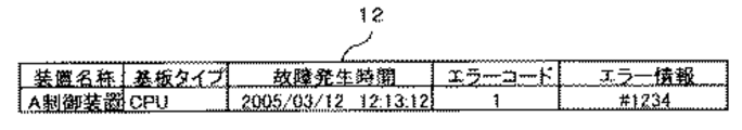
装置エラーログファイル12は、図2に示すように、装置名称、基板タイプ、故障発生時刻、エラー情報の各項目から構成され、各装置から収集した装置のエラーの情報を記憶するファイルである。装置故障リスト13は、図3に示すように、装置名称、基板タイプ、故障発生時刻、エラー情報の各項目から構成され、故障発生順に装置故障情報が蓄えられる。
As shown in FIG. 2, the device
装置構成情報データベース14は、図4に示すように、装置名称、基板タイプ、構成、IN、OUTの各項目から構成され、システム内の装置構成の構成情報をデータベースとしている。この装置構成情報データベース14は、装置内の基板構成にかかわる情報に加え、他の装置との関連付け情報(IN、OUT)を有している。他の装置との関連付け情報(IN、OUT)は、装置の入出力関係(上流下流関係)である。
As shown in FIG. 4, the device
装置故障データベース15は、図5に示すように、基板タイプ、エラーコード、エラー項目、エラー内容、解析コード、関連情報の各項目から構成され、装置の種類別にエラー定義をデータベースとしている。この装置故障データベース15は、基板タイプ毎に定義されたエラー項目をデータベース化したものであり、エラー項目に対して故障原因を関連情報と解析コードとして定義している。
As shown in FIG. 5, the
エラーログ収集手段16は、プラントのネットワーク上の装置からのエラーを一定周期で収集し装置エラーログファイル12に記憶する。故障検出手段17は装置エラーログファイル12から故障装置を検出し、故障発生順に装置故障リスト13を作成する。装置構成取得手段18は装置故障リスト13から故障した装置を取得して、その装置に関連する他の装置構成を取得する。プラント運転状態取得手段19は故障装置に関連する装置の運転状態を取得する。故障装置同定手段20は、故障装置、装置構成、装置の運転状態、装置のエラー定義がされた装置故障データベース15から故障装置の故障部位を同定する。そして、表示手段21は、故障装置同定手段20で同定された装置の故障部位を図示省略の表示装置に表示出力する。
The error log collection means 16 collects errors from the devices on the plant network at regular intervals and stores them in the device
次に動作について説明する。故障検出手段17は、エラーログ収集手段16が定期的に収集した各装置の装置エラーログファイル12を読み込みエラー発生している装置を検出する。そして、エラー発生している装置を検出すると、装置エラーログファイル12から装置エラー情報を取り出し、図3に示す装置故障リスト13のデータ構成に従い、装置故障リスト13に発生時間順にデータを書き込む。また、その装置エラー発生を装置構成取得手段18に通知する。
Next, the operation will be described. The
装置構成取得手段18は、装置故障リスト13より装置エラーを発生した装置を時系列に抽出し、その故障装置の構成情報を装置構成情報データベース14より取得する。図4に示すように装置構成情報データベース14は、装置内の基板構成にかかわる情報と他の装置との関連付けをデータデースにまとめている。装置構成取得手段18は、装置エラーで検出した装置を対象に装置構成情報データベース14より、基板情報、他装置との関連情報を取得する。装置構成取得手段18は、取得した装置構成情報をプラント運転状態取得手段19に受け渡す。
The device configuration acquisition means 18 extracts devices that have generated device errors from the
プラント運転状態取得手段19は、受け渡された装置情報を基に装置の稼動状態を取得する。装置構成でマルチ(2重化装置)と示された装置の両系の稼動状態や装置エラーになった装置に関連する他の装置の稼動状態を取得する。プラント運転状態取得手段19は、装置の稼動状態を故障装置同定手段20に受け渡す。 The plant operation state acquisition means 19 acquires the operation state of the apparatus based on the transferred apparatus information. The operation status of both systems of the device indicated as multi (duplex device) in the device configuration and the operation status of other devices related to the device in which a device error has occurred are acquired. The plant operating state acquisition means 19 delivers the operating state of the apparatus to the faulty apparatus identification means 20.
故障装置同定手段20は、図5に示す装置故障データベース15から装置エラーの装置のエラー情報を取得する。装置故障データベース15は、基板タイプ毎に定義されたエラー項目をデータベース化したものであり、エラー項目に対して故障原因を関連情報と解析コードとして定義し、装置の故障発生時に稼動中に把握したエラー原因を解析コードに置き換えてログへ出力される。
The failure device identification means 20 acquires device error information of a device error from the
図6は故障装置同定手段20における故障同定推論の処理内容を示すフローチャートである。この故障同定推論に基づき故障発生の真の装置を判定する。まず、推論1として「エラー情報は他の装置に関連するか?」を判定する(S1)。この判定は、装置故障リスト13からエラーコードを取得し、関連するコードであるか否かを判定することにより行われる。
FIG. 6 is a flowchart showing the processing contents of failure identification inference in the failure device identification means 20. Based on this fault identification reasoning, the true device in which the fault has occurred is determined. First, as
関連するコードである場合、推論2となり「関連装置で上流に位置する装置に故障発生しているか」を推論する(S2)。この推論は、図4に示した装置構成情報データベース14でINに設定される装置が装置故障リスト13の故障情報に存在するか否かを判断することで行われる。INに設定される装置が装置故障リスト13の故障情報に存在する場合は、故障を起こした真の装置を構成情報に記載しているINの装置に置き換えて、ステップS1に戻る(S3)。つまり、さらに推論1から他の装置との関連を推論する。
If it is a related code, it becomes
ステップS2の判定で、INに設定される装置が装置故障リスト13の故障情報に存在しない場合は、推論3として「装置エラーの装置はマルチ構成で二重化に関連するエラーが発生しているか?」を判定する(S4)。この判定は、同様にエラーコードから判定し、該当する場合は二重化の装置故障と判定する(S5)。
If it is determined in step S2 that the device set to IN does not exist in the failure information of the
ステップS4の判定で、装置エラーの装置がマルチ構成で二重化に関連するエラーではない場合は、個別装置の故障と判定する(S6)。また、ステップS1の判定で、エラー情報は他の装置に関連しない場合も個別装置の故障と判定する(S6)。 If it is determined in step S4 that the device error is not a multi-configuration error related to duplication, it is determined that the individual device is faulty (S6). Further, when the error information is not related to other devices in the determination in step S1, it is determined that the individual device is faulty (S6).
このようにして、真に故障を起こした装置が決定される。真の故障装置の故障情報の基板タイプ、エラーコード、エラー情報を基に、装置故障データベース15を検索し該当するエラー項目、エラー内容、関連情報を抽出し、それらの情報を表示手段21に受け渡す。表示手段21は、受け渡された装置情報、基盤タイプ、エラーコード、エラー項目、エラー内容、関連情報を所定の表示装置に表示する。
In this way, the device that has truly failed is determined. Based on the board type, error code, and error information of the failure information of the true failure device, the
第1の実施の形態によれば、エラーログ収集手段16により収集した装置故障情報からプラントにおける装置の運転状態を考慮した真の故障装置とその故障部位を同定できるので、信頼性が高く迅速な故障復旧ができる。 According to the first embodiment, since a true faulty device and its faulty part in consideration of the operation state of the device in the plant can be identified from the device fault information collected by the error log collecting means 16, it is highly reliable and quick. Fault recovery is possible.
(第2の実施の形態)
図7は本発明の第2の実施の形態に係る故障解析装置のブロック構成図である。この第2の実施の形態は、図1に示した第1の実施の形態に対し、各装置のプラントの所掌範囲(制御対象機器やプロセス入出力)をデータベースにまとめた装置管理情報データベース22と、この装置管理情報データベース22に基づいて故障装置同定手段20で故障部位が同定された故障装置によるプラントへの影響を推定する故障影響範囲推定手段23とを追加して設けたものである。図1と同一要素には同一符号を付し重複する説明は省略する。
(Second Embodiment)
FIG. 7 is a block diagram of a failure analysis apparatus according to the second embodiment of the present invention. This second embodiment is different from the first embodiment shown in FIG. 1 in that the device
装置故障同定手段20は、真の故障装置が決定した時点で、表示装置20にその旨を表示するとともに、故障影響範囲推定手段23に故障装置の情報を受け渡す。故障影響範囲推定手段23は、装置故障データベース15より故障装置につながるOUTに定義された装置を取得する。故障装置とOUTに定義された装置の運転状況をプラント運転状態取得手段19から取得する。また、装置故障とOUTに定義された装置の装置管理情報とを装置管理情報データベース22より系統、機器、プロセスI/O情報を抽出する。
When the true faulty device is determined, the device
図8は装置管理情報データベース22のデータ構成図である。装置管理情報データベース22は、図8に示すように、装置名称、系統、機器、プロセスI/Oの各項目から構成され、各装置のプラントの所掌範囲(制御対象機器やプロセス入出力)をデータベース化したものである。すなわち、装置管理情報データベース22は、個々の装置毎に、その装置が担当する系統や制御を行う機器や他装置と取合うプロセス入出力信号を予め定義したデータベースとなっている。
FIG. 8 is a data configuration diagram of the device
故障影響範囲推定手段23は、故障装置と関連する装置の運転状態と装置の構成情報(マルチ構成か否か)を基に装置管理情報データベース22より取得し装置が停止、または、上流側に位置する装置が停止しているなら、その情報を表示手段21に受け渡す。
The failure influence range estimation means 23 obtains from the device
表示手段21は、故障影響範囲推定手段23より受け渡された装置情報に基づいて、装置停止で影響が及ぶ系統や制御できない機器、プロセス入出力範囲を所定の表示装置に表示する。
Based on the device information delivered from the failure influence
第2の実施の形態によれば、第1の実施の効果に加え、故障影響範囲推定手段23により故障した装置がプラント運転への影響範囲を具体的に迅速に把握できるので、プラント運転への悪影響を最小限に抑制しつつ迅速な故障復旧ができる。 According to the second embodiment, in addition to the effects of the first embodiment, the failure influence range estimation means 23 can be used to quickly and specifically grasp the influence range on the plant operation by the failure device, so Quick failure recovery is possible while minimizing adverse effects.
(第3の実施の形態)
図9は本発明の第3の実施の形態に係る故障解析装置のブロック構成図である。この第3の実施の形態は、図7に示した第2の実施の形態に対し、ネットワーク上のネットワーク構成機器と装置との関連をデータベース化したネットワーク構成情報データベース24と、故障装置同定手段20で故障部位が同定された故障装置がネットワーク機器である場合にネットワーク構成情報データベース24に基づいてネットワーク故障の影響を推定しこの影響する装置を故障影響範囲推定手段23に出力するネットワーク影響範囲推定手段25とを設けたものである。図7と同一要素には同一符号を付し重複する説明は省略する。
(Third embodiment)
FIG. 9 is a block diagram of a failure analysis apparatus according to the third embodiment of the present invention. This third embodiment is different from the second embodiment shown in FIG. 7 in that a network
図9において、ネットワーク構成情報データベース24はネットワーク上のネットワーク構成機器と装置との関連をデータベース化したものであり、ネットワーク影響範囲推定手段25は、故障装置同定手段20で故障部位が同定された故障装置がネットワーク機器である場合に、ネットワーク構成情報データベース24に基づいてネットワーク故障の影響を推定し、この影響する装置を故障影響範囲推定手段23に出力する。
In FIG. 9, the network
装置にネットワーク機器が含まれる場合には、図10に示すように装置構成情報データベース14に、装置間を繋げるネットワークのネットワーク構成機器である「ルータ」等を定義し、基板タイプを「NET」と定義して装置構成情報を広範囲の構成情報定義データベースとする。
When the device includes a network device, as shown in FIG. 10, the device
図11は本発明の第3の実施の形態におけるネットワーク構成情報データベース24のデータ構成図である。図11に示すように、ネットワーク構成情報データベース24は、装置名称、上位ネットワーク装置、下位ネットワーク装置、接続装置の各項目から構成され、階層の異なるネットワークを接続するネットワーク機器(ルータ等)を階層のつながりで上下関係を定義し、さらに個々のネットワーク上に接続する装置を定義するデータベースである。ネットワーク構成情報データベース24は、故障したネットワーク機器の構成情報として上位ネットワーク機器、下位ネットワーク機器、接続装置の情報を提供する。
FIG. 11 is a data configuration diagram of the network
次に動作について説明する。装置故障同定手段20は、真の故障装置が決定した時点で、表示装置20にその旨を表示するとともに、故障装置の基板タイプが「NET」となっている場合は、ネットワーク故障影響範囲推定手段25にネットワーク機器の情報を受け渡す。
Next, the operation will be described. When the true faulty device is determined, the device
ネットワーク故障影響範囲推定手段25は、ネットワーク構成情報データベース24より故障したネットワーク機器の構成情報として上位ネットワーク機器、下位ネットワーク機器、接続装置の情報を取得する。また、ネットワーク故障影響範囲推定手段25は、故障したネットワーク機器の管理するネットワークに接続する装置を把握する。故障したネットワーク機器の下位に位置するネットワーク機器が存在する場合は、さらに下位に位置するネットワーク機器が管理する装置を把握する。
The network failure influence
このよう形式で下位の全てのネットワークに接続する装置を把握し、ネットワーク故障における装置への影響範囲を決定する。この影響する装置を故障影響範囲推定手段23に受け渡す。これより先の処理は、第2の実施の形態の故障影響範囲推定手段23と同様であるので説明は省略する。これにより、ネットワーク上のネットワーク機器の故障による故障影響範囲の表示が可能となる。 In this way, devices connected to all lower networks are grasped, and the range of influence on devices due to network failures is determined. The affected device is transferred to the failure influence range estimation means 23. Since the processing after this is the same as that of the failure influence range estimation means 23 of the second embodiment, description thereof is omitted. As a result, it is possible to display a failure influence range due to a failure of a network device on the network.
第3の実施の形態によれば、第2の実施の形態の効果に加え、ネットワーク影響範囲推定手段25により故障した装置がネットワーク機器の故障においてもプラントの運転でどこまで影響するか迅速に伝達でき状況把握が容易となる。 According to the third embodiment, in addition to the effects of the second embodiment, the network influence range estimation means 25 can quickly transmit to the extent that the faulty device affects the plant operation even in the case of a network equipment failure. The situation can be easily grasped.
(第4の実施の形態)
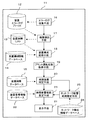
図12は本発明の第4の実施の形態に係る故障解析装置のブロック構成図である。この第4の実施の形態は、図7に示した第2の実施の形態に対し、装置構成情報データベースに基づいて前記故障装置同定手段で故障部位が同定された故障装置の故障部位の交換が可能かどうかを判定する故障装置基板交換判定手段26を設けたものである。図7と同一要素には同一符号を付し重複する説明は省略する。
(Fourth embodiment)
FIG. 12 is a block diagram of a failure analysis apparatus according to the fourth embodiment of the present invention. This fourth embodiment is different from the second embodiment shown in FIG. 7 in that the failure part of the failure device whose failure part is identified by the failure device identification means based on the device configuration information database is replaced. A faulty device board replacement judging means 26 for judging whether or not it is possible is provided. The same elements as those in FIG.
図12において、故障装置基板交換判定手段26は、故障影響範囲推定手段23で影響範囲を確定した後、故障装置の故障部位(基板等)の交換を判定し、その判定結果である故障装置の基板交換情報は表示手段21にて表示装置に表示される。 In FIG. 12, the failure device board replacement determination means 26 determines the replacement of the failure part (substrate etc.) of the failure device after the influence range is determined by the failure influence range estimation means 23, and the determination result of the failure device is the determination result. The board replacement information is displayed on the display device by the display means 21.
すなわち、故障装置基板交換判定手段26は、故障影響範囲推定手段23で同定された故障装置と故障基板との情報を基に、装置構成情報データベース14を参照し、該当装置の構成情報で二重化となっているか否かを判定するとともに、他の装置との関係をIN、OUTの情報から判断して、故障基板が交換可能かを判定する。判断した結果は表示手段21から表示装置に表示される。
That is, the faulty device board
第4の実施の形態によれば、第2の実施の形態の効果に加え、故障装置基板交換判定手段26により故障した装置の故障基板が交換可能かの判定結果を出力するので、基板交換作業を行う際の手助けとなり迅速な故障復旧ができる。 According to the fourth embodiment, in addition to the effects of the second embodiment, the failure device substrate replacement determination means 26 outputs a determination result indicating whether the failed substrate of the failed device can be replaced. It can be a help when performing repairs, and quick failure recovery is possible.
(第5の実施の形態)
図13は本発明の第5の実施の形態に係る故障解析装置のブロック構成図である。この第5の実施の形態は、図12に示した第4の実施の形態に対し、予備品管理データベース27と、予備品管理データベース27に基づいて前記故障装置同定手段で故障部位が同定された故障装置の故障部位の交換予備品を確認する交換基板予備品確認手段28とを設けたものである。図12と同一要素には同一符号を付し重複する説明は省略する。
(Fifth embodiment)
FIG. 13 is a block diagram of a failure analysis apparatus according to the fifth embodiment of the present invention. This fifth embodiment is different from the fourth embodiment shown in FIG. 12 in that the faulty part is identified by the faulty device identification means based on the spare
図13において、装置単位の基板の予備品数をデータベース化した予備品管理データベース27と、故障装置の故障部位(基板等)の交換予備品を確認する交換基板予備品確認手段28とが追加して設けられている。
In FIG. 13, a spare
予備品管理データベース27は、図14に示すように、装置名称、基板タイプ、予備数、バージョンの各項目から構成される。また、装置構成データベース14に、図15に示すように基板のバージョン情報を持たせる。
As shown in FIG. 14, the spare
交換基板予備品確認手段28は、故障装置基板交換判定手段26にて交換可能と判断された装置の基板に対して、予備品管理データベース27から該当基板の予備品数やバージョンを確認し、装置構成データベース14に持たせた基板のバージョン情報に基づいて、予備基板と実装基板のバージョンとの整合を判断し、現在の交換基板の保有量を表示手段21を介して表示装置に表示する。これにより、故障装置の故障部位の交換予備品の確認が容易に行える。
The replacement board spare part confirmation means 28 confirms the number of spare parts and the version of the corresponding board from the spare
以上の説明では、装置構成情報データベース14には装置間を繋げるネットワークのネットワーク構成機器である「ルータ」がない場合について説明したが、図9に示した第3の実施の形態のように、ネットワーク構成情報データベース34及びネットワーク影響範囲推定手段25を設けた場合には、装置構成情報データベース14に、装置間を繋げるネットワークのネットワーク構成機器である「ルータ」等を定義し、基板タイプを「NET」と定義して装置構成情報を広範囲の構成情報定義データベースとする。この場合には、予備品管理データベース27にも「ルータ」を定義することになる。
In the above description, the case where the device
第5の実施の形態によれば、第4の実施の形態の効果に加え、交換基板予備品確認手段28により故障した装置の予備品の確認を行うので、基板交換作業を行う際の判断の手助けとなる。 According to the fifth embodiment, in addition to the effects of the fourth embodiment, the replacement substrate spare part confirmation means 28 checks the spare part of the failed device. Will help.
11…故障診断装置、12…装置エラーログファイル、13…装置故障リスト、14…装置構成情報データベース、15…装置故障データベース、16…エラーログ収集手段、17…故障検出手段、18…装置構成取得手段、19…プラント運転状態取得手段、20…故障装置同定手段、21…表示手段、22…装置管理情報データベース、23…故障影響範囲推定手段、24…ネットワーク構成情報データベース、25…ネットワーク影響範囲推定手段、26…故障装置基板交換判定手段、27…予備品管理データベース、28…交換基板予備品確認手段
DESCRIPTION OF
Claims (5)
A replacement board spare part confirmation unit for confirming a replacement spare part of a faulty part of the faulty device whose faulty part has been identified by the faulty unit identification unit based on a spare part management database in which the number of spare parts of the board in units of devices is made into a database. The failure analysis device according to claim 1, wherein the failure analysis device is a failure analysis device.
Priority Applications (1)
| Application Number | Priority Date | Filing Date | Title |
|---|---|---|---|
| JP2006084648A JP2007257581A (en) | 2006-03-27 | 2006-03-27 | Failure analysis device |
Applications Claiming Priority (1)
| Application Number | Priority Date | Filing Date | Title |
|---|---|---|---|
| JP2006084648A JP2007257581A (en) | 2006-03-27 | 2006-03-27 | Failure analysis device |
Publications (1)
| Publication Number | Publication Date |
|---|---|
| JP2007257581A true JP2007257581A (en) | 2007-10-04 |
Family
ID=38631718
Family Applications (1)
| Application Number | Title | Priority Date | Filing Date |
|---|---|---|---|
| JP2006084648A Pending JP2007257581A (en) | 2006-03-27 | 2006-03-27 | Failure analysis device |
Country Status (1)
| Country | Link |
|---|---|
| JP (1) | JP2007257581A (en) |
Cited By (5)
| Publication number | Priority date | Publication date | Assignee | Title |
|---|---|---|---|---|
| WO2013140633A1 (en) * | 2012-03-23 | 2013-09-26 | 富士通株式会社 | Replacement candidate presentation method, information processing device and program |
| WO2014091653A1 (en) | 2012-12-12 | 2014-06-19 | 三菱電機株式会社 | Monitor control device and monitor control method |
| JP2015088591A (en) * | 2013-10-30 | 2015-05-07 | 株式会社荏原製作所 | Failure place specification device and substrate processor |
| CN110727571A (en) * | 2019-10-22 | 2020-01-24 | 中影环球(北京)科技有限公司 | Cinema projection equipment fault detection method and system |
| JP7450839B1 (en) | 2023-08-09 | 2024-03-15 | 三菱電機株式会社 | Information management device, information management system, information management method, and program |
-
2006
- 2006-03-27 JP JP2006084648A patent/JP2007257581A/en active Pending
Cited By (8)
| Publication number | Priority date | Publication date | Assignee | Title |
|---|---|---|---|---|
| WO2013140633A1 (en) * | 2012-03-23 | 2013-09-26 | 富士通株式会社 | Replacement candidate presentation method, information processing device and program |
| JPWO2013140633A1 (en) * | 2012-03-23 | 2015-08-03 | 富士通株式会社 | Exchange candidate presentation method, information processing apparatus, and program |
| WO2014091653A1 (en) | 2012-12-12 | 2014-06-19 | 三菱電機株式会社 | Monitor control device and monitor control method |
| US10274946B2 (en) | 2012-12-12 | 2019-04-30 | Mitsubishi Electric Corporation | Monitoring control apparatus and monitoring control method |
| JP2015088591A (en) * | 2013-10-30 | 2015-05-07 | 株式会社荏原製作所 | Failure place specification device and substrate processor |
| CN110727571A (en) * | 2019-10-22 | 2020-01-24 | 中影环球(北京)科技有限公司 | Cinema projection equipment fault detection method and system |
| CN110727571B (en) * | 2019-10-22 | 2023-10-13 | 中影环球(北京)科技有限公司 | Cinema projection equipment fault detection method and system |
| JP7450839B1 (en) | 2023-08-09 | 2024-03-15 | 三菱電機株式会社 | Information management device, information management system, information management method, and program |
Similar Documents
| Publication | Publication Date | Title |
|---|---|---|
| JP4948679B1 (en) | Servo control device abnormality diagnosis device and abnormality diagnosis system | |
| JP4911080B2 (en) | Quality improvement system | |
| JP5200970B2 (en) | Quality control system, quality control device and quality control program | |
| JP2009110281A (en) | Medical equipment failure analyzing device, medical equipment failure analyzing method, and medical equipment failure analyzing system | |
| JP2007257581A (en) | Failure analysis device | |
| RU2667032C2 (en) | Information-search system and method | |
| JP4648961B2 (en) | Apparatus maintenance system, method, and information processing apparatus | |
| JP2008305173A (en) | Maintenance device, maintenance method and program for paper sheet processor | |
| JPH10312321A (en) | On-line system fault analyzing method | |
| JP5322581B2 (en) | Station service system | |
| US20220035359A1 (en) | System and method for determining manufacturing plant topology and fault propagation information | |
| JP2010092173A (en) | Process diagnostic method and system thereof | |
| JP6070040B2 (en) | Database system, database device, database failure recovery method and program | |
| US9372746B2 (en) | Methods for identifying silent failures in an application and devices thereof | |
| EP3820655B1 (en) | Diagnosis method and apparatus | |
| JP2011192201A (en) | Remote maintenance system and remote maintenance method | |
| CN111552263A (en) | Method, computer-readable storage medium, and system for inspecting an industrial facility | |
| JP2009059204A (en) | Computer remote control system | |
| JP2005250577A (en) | Computer system and soundness determination means of arithmetic processing module | |
| JP2005071200A (en) | Manufacturing information management program | |
| JPH11345003A (en) | Plant control system | |
| JP2020083492A (en) | Repeated failure prevention device, repeated failure prevention system and repeated failure prevention method | |
| JP7398019B1 (en) | Maintenance support device and maintenance support method | |
| JP4691285B2 (en) | Product usage environment information collection and analysis equipment | |
| WO2022168269A1 (en) | Information processing device, information processing method, and information processing program |