JP2007252018A - Permanent magnet motor - Google Patents
Permanent magnet motor Download PDFInfo
- Publication number
- JP2007252018A JP2007252018A JP2006067755A JP2006067755A JP2007252018A JP 2007252018 A JP2007252018 A JP 2007252018A JP 2006067755 A JP2006067755 A JP 2006067755A JP 2006067755 A JP2006067755 A JP 2006067755A JP 2007252018 A JP2007252018 A JP 2007252018A
- Authority
- JP
- Japan
- Prior art keywords
- rotor
- insertion hole
- magnetic pole
- permanent magnet
- wall
- Prior art date
- Legal status (The legal status is an assumption and is not a legal conclusion. Google has not performed a legal analysis and makes no representation as to the accuracy of the status listed.)
- Pending
Links
Images


Classifications
-
- H—ELECTRICITY
- H02—GENERATION; CONVERSION OR DISTRIBUTION OF ELECTRIC POWER
- H02K—DYNAMO-ELECTRIC MACHINES
- H02K1/00—Details of the magnetic circuit
- H02K1/06—Details of the magnetic circuit characterised by the shape, form or construction
- H02K1/22—Rotating parts of the magnetic circuit
- H02K1/32—Rotating parts of the magnetic circuit with channels or ducts for flow of cooling medium
-
- H—ELECTRICITY
- H02—GENERATION; CONVERSION OR DISTRIBUTION OF ELECTRIC POWER
- H02K—DYNAMO-ELECTRIC MACHINES
- H02K1/00—Details of the magnetic circuit
- H02K1/06—Details of the magnetic circuit characterised by the shape, form or construction
- H02K1/22—Rotating parts of the magnetic circuit
- H02K1/27—Rotor cores with permanent magnets
- H02K1/2706—Inner rotors
- H02K1/272—Inner rotors the magnetisation axis of the magnets being perpendicular to the rotor axis
- H02K1/274—Inner rotors the magnetisation axis of the magnets being perpendicular to the rotor axis the rotor consisting of two or more circumferentially positioned magnets
- H02K1/2753—Inner rotors the magnetisation axis of the magnets being perpendicular to the rotor axis the rotor consisting of two or more circumferentially positioned magnets the rotor consisting of magnets or groups of magnets arranged with alternating polarity
- H02K1/276—Magnets embedded in the magnetic core, e.g. interior permanent magnets [IPM]
-
- H—ELECTRICITY
- H02—GENERATION; CONVERSION OR DISTRIBUTION OF ELECTRIC POWER
- H02K—DYNAMO-ELECTRIC MACHINES
- H02K2213/00—Specific aspects, not otherwise provided for and not covered by codes H02K2201/00 - H02K2211/00
- H02K2213/03—Machines characterised by numerical values, ranges, mathematical expressions or similar information
Landscapes
- Engineering & Computer Science (AREA)
- Power Engineering (AREA)
- Iron Core Of Rotating Electric Machines (AREA)
- Motor Or Generator Cooling System (AREA)
- Permanent Magnet Type Synchronous Machine (AREA)
- Permanent Field Magnets Of Synchronous Machinery (AREA)
Abstract
Description
本発明は、永久磁石を用いた永久磁石電動機、特に、回転子に設けられている磁石挿入孔に永久磁石が挿入されている永久磁石電動機に関する。 The present invention relates to a permanent magnet motor using a permanent magnet, and more particularly to a permanent magnet motor in which a permanent magnet is inserted into a magnet insertion hole provided in a rotor.
空調装置(エアコン)や冷蔵庫等の圧縮機(コンプレッサ)を駆動する電動機、車両を駆動する電動機や車両に搭載されている車載機器を駆動する電動機として、磁石挿入孔に永久磁石が挿入された回転子を有する永久磁石電動機が用いられている。このような永久磁石電動機は、通常、“永久磁石埋込型電動機(IPMモータ)”と呼ばれている。
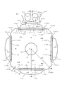
圧縮機を駆動する電動機(圧縮機駆動用電動機)として用いられる永久磁石電動機は、例えば、図21に示す構成を有している。図21は、永久磁石電動機の、軸方向に直角な断面図である。永久磁石電動機は、回転子910と固定子930を備えている。
回転子910は、電磁鋼板を積層して形成される回転子鉄心(回転子コア)911により構成されている。回転子910(厳密には、回転子鉄心911)には、回転軸920を挿入する回転軸挿入孔919が設けられている。また、回転子910には、主磁極部と補助磁極部が周方向に交互に設けられている。主磁極部には、永久磁石912a〜912dを挿入する磁石挿入孔911a〜911dが設けられている。なお、隣接する主磁極部の磁石挿入孔911a〜911dには、異なる極性の永久磁石が挿入される。
固定子930は、電磁鋼板を積層して形成される固定子鉄心(固定子コア)931により構成されている。固定子930(厳密には、固定子鉄心931)には、回転子910の外周面と対向する個所にティース932が形成されている。ティース932によってスロット933が形成され、スロット933内には固定子コイル(図示省略)が収納される。固定子930は、リング(ケース)940内に収容される。
エアコン(空調装置)は、永久磁石電動機により駆動され、冷却媒体を圧縮する圧縮機、冷却媒体の熱を放熱する室外熱交換器、室内の空気から熱を吸収する室内熱交換器等により構成されており、冷却媒体が循環するように構成されている。ここで、冷却媒体が永久磁石電動機(圧縮機駆動用電動機)内を通過できるようにするために、永久磁石電動機には、冷却媒体を流す冷却媒体通路が、軸方向に連通して設けられている。例えば、図21に示すように、固定子930(固定子鉄心931)の外周面に、軸方向に沿って切欠部934aが形成されている。そして、切欠部934aとリング(ケース)940によって、軸方向に連通する連通孔934が構成される。この連通孔934が冷却媒体通路として用いられる。なお、永久磁石電動機の回転子と固定子の間の間隙(ギャップ)も冷却媒体通路として用いられる。
なお、永久磁石電動機の回転子910(回転子鉄心911)に、軸方向に連通する連通孔を設け、連通孔を冷却媒体通路として用いたものも知られている。(特許文献1参照)
A permanent magnet motor used as an electric motor for driving the compressor (compressor driving electric motor) has, for example, the configuration shown in FIG. FIG. 21 is a cross-sectional view of the permanent magnet motor perpendicular to the axial direction. The permanent magnet motor includes a rotor 910 and a stator 930.
The rotor 910 includes a rotor core (rotor core) 911 formed by laminating electromagnetic steel plates. The rotor 910 (strictly speaking, the rotor core 911) is provided with a rotation shaft insertion hole 919 into which the rotation shaft 920 is inserted. Further, the rotor 910 is provided with main magnetic pole portions and auxiliary magnetic pole portions alternately in the circumferential direction. Magnet insertion holes 911a to 911d for inserting permanent magnets 912a to 912d are provided in the main magnetic pole portion. In addition, permanent magnets having different polarities are inserted into the magnet insertion holes 911a to 911d of the adjacent main magnetic pole portions.
The stator 930 includes a stator core (stator core) 931 formed by laminating electromagnetic steel plates. In the stator 930 (strictly speaking, the stator core 931), teeth 932 are formed at locations facing the outer peripheral surface of the rotor 910. A slot 933 is formed by the teeth 932, and a stator coil (not shown) is accommodated in the slot 933. The stator 930 is accommodated in a ring (case) 940.
An air conditioner (air conditioner) is driven by a permanent magnet motor, and includes a compressor that compresses a cooling medium, an outdoor heat exchanger that radiates heat from the cooling medium, an indoor heat exchanger that absorbs heat from indoor air, and the like. The cooling medium is circulated. Here, in order to allow the cooling medium to pass through the permanent magnet motor (motor for driving the compressor), the permanent magnet motor is provided with a cooling medium passage through which the cooling medium flows in the axial direction. Yes. For example, as shown in FIG. 21, a notch 934a is formed along the axial direction on the outer peripheral surface of the stator 930 (stator core 931). The notch 934a and the ring (case) 940 constitute a communication hole 934 that communicates in the axial direction. This communication hole 934 is used as a cooling medium passage. Note that a gap (gap) between the rotor and the stator of the permanent magnet motor is also used as the cooling medium passage.
It is also known that a rotor 910 (rotor core 911) of a permanent magnet motor is provided with a communication hole communicating in the axial direction, and the communication hole is used as a cooling medium passage. (See Patent Document 1)
圧縮機、例えば、ロータリーコンプレッサは、密閉容器内に、圧縮機の機械部分を潤滑する潤滑油が噴霧状の状態で冷却媒体と混在している。ここで、永久磁石電動機に設けられている冷却媒体通路の総断面積が小さい場合には、冷却媒体の速度が速くなる。冷却媒体の速度が遅い場合には、噴霧状の潤滑油は自重で落下するが、冷却媒体の速度が速い場合には、噴霧状の潤滑油は冷却媒体とともに圧縮機の吐出管から排出される。噴霧状の潤滑油が圧縮機の吐出管から吐出されると、熱交換器での熱交換効率が低下する。したがって、圧縮機駆動用電動機として用いられている永久磁石電動機に設けられている冷却媒体通路(連通孔)の総断面積が大きい方が好ましい。
一方、固定子に設けられる冷却媒体通路(連通孔)の総断面積が大きくなると、固定子の磁束通路が狭くなり、固定子の磁束密度が高くなる。固定子の磁束密度が高くなると、固定子の鉄損が増大し、永久磁石電動機の効率が低下する。
このため、固定子に設けられる冷却媒体通路(連通孔)の総断面積の増大を抑えながら、永久磁石電動機に設けられる冷却媒体通路(連通孔)の総断面積を増大させる技術の開発が要望されている。
ここで、固定子に設ける連通孔の総断面積を抑えながら、永久磁石電動機に設ける連通孔の総断面積を大きくする方法として、特許文献1に記載されている、回転子に連通孔を設ける技術を用いることが考えられる。
しかしながら、本発明者による検討の結果、回転子に連通孔を設ける場合、連通孔の配設位置によって永久磁石電動機の効率が大きく変化することを見出した。
本発明は、永久磁石電動機の効率低下を抑制しながら、回転子に連通孔を設けることができる技術を提供することを目的とする。
In a compressor, for example, a rotary compressor, a lubricating oil that lubricates a mechanical part of the compressor is mixed with a cooling medium in a spray state in a sealed container. Here, when the total cross-sectional area of the cooling medium passage provided in the permanent magnet motor is small, the speed of the cooling medium is increased. When the speed of the cooling medium is low, the spray-like lubricating oil falls by its own weight, but when the speed of the cooling medium is high, the spray-like lubricating oil is discharged from the discharge pipe of the compressor together with the cooling medium. . When the sprayed lubricating oil is discharged from the discharge pipe of the compressor, the heat exchange efficiency in the heat exchanger is lowered. Therefore, it is preferable that the total cross-sectional area of the coolant passage (communication hole) provided in the permanent magnet motor used as the compressor driving motor is large.
On the other hand, when the total cross-sectional area of the cooling medium passage (communication hole) provided in the stator is increased, the magnetic flux passage of the stator is narrowed and the magnetic flux density of the stator is increased. When the magnetic flux density of the stator increases, the iron loss of the stator increases and the efficiency of the permanent magnet motor decreases.
Therefore, it is desired to develop a technology for increasing the total cross-sectional area of the cooling medium passage (communication hole) provided in the permanent magnet motor while suppressing the increase in the total cross-sectional area of the cooling medium passage (communication hole) provided in the stator. Has been.
Here, as a method of increasing the total cross-sectional area of the communication hole provided in the permanent magnet motor while suppressing the total cross-sectional area of the communication hole provided in the stator, the communication hole is provided in the rotor described in
However, as a result of studies by the present inventors, it has been found that when the communication hole is provided in the rotor, the efficiency of the permanent magnet motor varies greatly depending on the position of the communication hole.
An object of this invention is to provide the technique which can provide a communicating hole in a rotor, suppressing the efficiency fall of a permanent magnet motor.
前記課題を解決するための本発明の第1発明は、請求項1に記載されたとおりの永久磁石電動機である。
本発明の永久磁石電動機は、空調装置(エアコン)や冷蔵庫等の圧縮機(コンプレッサ)を駆動する電動機(圧縮機駆動電動機)、車両を駆動する電動機や車両に搭載されている車載機器を駆動する電動機等種々の用途に用いることができる。
本発明の永久磁石電動機は、固定子と回転子を備えている。固定子は、典型的には、電磁鋼板を積層して形成される固定子鉄心により構成される。固定子には、回転子の外周面と対向する箇所にティースが設けられている。ティースは、典型的には、ティース基部と、ティース基部の周方向両側に設けられているティース端部により構成され、ティース基部とティース端部の先端側の端面によってティース先端面が形成される。ティースによってスロットが形成されており、スロットには、固定子巻線が収納されている。
回転子は、典型的には、積層鋼板を積層して形成される回転子鉄心により構成される。回転子には、回転軸挿入孔が設けられている。また、回転子には、軸方向に直角な断面で見て、主磁極部と補助磁極部が周方向に交互に配置されている。主磁極部には磁石挿入孔が設けられており、磁石挿入孔には、隣接する主磁極部で極性が異なるように永久磁石が挿入されている。これにより、永久磁石の磁束によるマグネットトルクと、補助磁極部の突極性によるリラクタンストルクの両方を利用することができる。
磁石挿入孔は、軸方向に直角な断面で見て、回転軸挿入孔側に配置されている内壁と、内壁に対して回転軸挿入孔と反対側に配置されている外壁と、回転子の外周面に対向する位置に配置されている端壁により構成されている。典型的には、内壁と外壁は平行(略平行を含む)に形成され、端壁は、回転子の外周面と平行(略平行を含む)に形成される。磁石挿入孔の形状によっては、内側側壁や外側側壁が設けられる。
さらに、回転子には、軸方向に連通する連通孔が設けられている。回転子の連通孔は、典型的には、回転子を構成する回転子鉄心に形成された孔によって構成される。本発明では、連通孔を、磁石挿入孔の内壁に沿った線に平行であり、内壁に沿った線から回転軸挿入口側にティース幅だけ離れた第1の境界線と内壁に沿った線により形成される第1の領域と、内壁に沿った線と主磁極部のd軸と交差する点から隣接する主磁極部の方向に延び、回転子の飽和磁束密度と、磁石挿入孔に挿入された永久磁石から回転子に流れる磁束の磁束密度との比を傾きとする第2の境界線と内壁に沿った線により形成される第2の領域に設けないように設定している。「連通孔を第1の領域と第2の領域に設けない」構成は、第1の領域及び第2の領域のいずれにも連通孔が設けられていない構成を意味する。第1の境界線と内壁に沿った線により形成される第1の領域は、第1の境界線上の領域を含まないように設定するのが好ましい。また、第2の境界線と内壁に沿った線により形成される第2の領域は、第2の境界線上の領域を含まないように設定する方が好ましい。
第1の境界線と内壁に沿った線により第1の領域を形成する構成、第2の境界線と内壁に沿った線により第2の領域を形成する構成には、第1の境界線と内壁に沿った線とさらに他の線(例えば、内側側線)により第1の領域を形成する態様、第2の境界線と内壁に沿った線とさらに他の線(例えば、内側側壁)により第2の領域を形成する態様を包含する。
なお、一般的に、永久磁石電動機を設計する場合には、磁石挿入孔に挿入された永久磁石から回転子(回転子鉄心)に流れる磁束の磁束密度(設計磁束密度)は、永久磁石の磁束密度(設定磁束密度)より小さくなるように設計される。
ここで、回転子の軸方向に直角な断面において、回転子の中心と主磁極部の周方向中央部とを結ぶ線を「d軸」という。
磁石挿入孔の内壁に沿った線は、主磁極部に一つの磁石挿入孔が設けられている場合には、一つの磁石挿入孔の内壁に沿った線を意味し、主磁極部に周方向に沿って複数の磁石挿入孔が設けられている場合には、各磁石挿入孔の内壁に沿って線を結んだ線を意味し、主磁極部に、回転軸挿入孔から回転子の外周面の方向に複数の磁石挿入孔が設けられている場合には、回転軸挿入孔側に設けられている磁石挿入孔の内壁に沿った線を意味する。第2の境界線の傾きは、回転子の飽和磁束密度と磁石挿入孔に挿入される永久磁石から回転子に流れる磁束の磁束密度の比によって決定されるため、回転子を構成する材料や永久磁石を構成する材料によって異なる。
連通孔を、第1の境界線と内壁に沿った線により形成される第1の領域に設けないことにより、q軸磁束を流す磁束通路を確保することができる。これにより、リラクタンストルクの低下を抑制しながら(永久磁石電動機の効率低下を抑制しながら)連通孔を回転子に設けることができる。また、連通孔を、第2の境界線と内壁に沿った線により形成される第2の領域に設けないことにより、d軸磁束を流す磁束通路を確保することができる。これにより、マグネットトルクの低下を抑制しながら(永久磁石電動機の効率低下を抑制しながら)連通孔を回転子に設けることができる。本発明では、q軸磁束を流す磁束通路の確保による効率低下抑制効果と、d軸磁束を流す磁束通路の確保による効率低下抑制効果を得ることができる。
一般的に、電磁鋼板を積層して形成される回転子鉄心により回転子を構成する場合には、回転子鉄心を一体的に固定するためのカシメピンを挿入するカシメピン挿入孔が設けられる。カシメピン挿入孔の配設位置は、磁石挿入孔の形状等によって選択される。本発明の「回転子の連通孔」は、カシメピンを挿入するためのカシメピン挿入孔を包含しない。本発明の「回転子の連通孔」は、典型的には、熱交換器に供給する冷却媒体を流す冷却媒体通路、回転子を冷却する冷却媒体(例えば、冷却風)を流す冷却用通路、回転子の重量を低減するための孔として使用される。カシメピン挿入孔が第1の領域や第2の領域に設けられる場合には、例えば、磁性体で構成されたカシメピンを用いることにより、本発明の効果が低減するのを防止することができる。
なお、本発明の永久磁石電動機を、固定子に設けた連通孔と回転子に設けた連通孔によって冷却媒体通路を構成する圧縮機駆動用電動機として用いる場合には、固定子に設ける連通孔の総断面積を低減する構成と、効率低下を抑制しながら回転子に連通孔を設ける構成を組み合わせることができる。これにより、冷却媒体通路の総断面積を確保しながら、永久磁石電動機全体の効率を向上させることができる。
A first invention of the present invention for solving the above problem is a permanent magnet electric motor as set forth in
The permanent magnet motor of the present invention drives an electric motor (compressor drive motor) that drives a compressor (compressor) such as an air conditioner (air conditioner) or a refrigerator, an electric motor that drives a vehicle, and an in-vehicle device mounted on the vehicle. It can be used for various applications such as electric motors.
The permanent magnet motor of the present invention includes a stator and a rotor. The stator is typically composed of a stator core formed by stacking electromagnetic steel plates. The stator is provided with teeth at positions facing the outer peripheral surface of the rotor. The teeth are typically configured by a teeth base and teeth ends provided on both sides in the circumferential direction of the teeth base, and a teeth tip surface is formed by the teeth base and the end surfaces of the teeth end on the tip side. A slot is formed by the teeth, and a stator winding is accommodated in the slot.
The rotor is typically composed of a rotor core formed by stacking laminated steel plates. The rotor is provided with a rotation shaft insertion hole. Further, the main magnetic pole portion and the auxiliary magnetic pole portion are alternately arranged in the circumferential direction on the rotor as viewed in a cross section perpendicular to the axial direction. A magnet insertion hole is provided in the main magnetic pole portion, and a permanent magnet is inserted into the magnet insertion hole so that the polarity is different between adjacent main magnetic pole portions. Thereby, both the magnet torque by the magnetic flux of a permanent magnet and the reluctance torque by the saliency of an auxiliary | assistant magnetic pole part can be utilized.
The magnet insertion hole has an inner wall disposed on the rotation shaft insertion hole side, an outer wall disposed on the opposite side of the rotation shaft insertion hole with respect to the inner wall, and a rotor It is comprised by the end wall arrange | positioned in the position facing an outer peripheral surface. Typically, the inner wall and the outer wall are formed in parallel (including substantially parallel), and the end wall is formed in parallel (including substantially parallel) with the outer peripheral surface of the rotor. Depending on the shape of the magnet insertion hole, an inner side wall or an outer side wall is provided.
Further, the rotor is provided with a communication hole communicating in the axial direction. The communication hole of the rotor is typically configured by a hole formed in the rotor core that forms the rotor. In the present invention, the communication hole is parallel to the line along the inner wall of the magnet insertion hole, and the first boundary line and the line along the inner wall that are separated from the line along the inner wall by the tooth width toward the rotary shaft insertion port side. Extends from the point intersecting the d-axis of the main magnetic pole part and the line along the inner wall to the adjacent main magnetic pole part and inserted into the rotor saturation magnetic flux density and the magnet insertion hole It is set so as not to be provided in the second region formed by the second boundary line and the line along the inner wall having an inclination with respect to the magnetic flux density of the magnetic flux flowing from the permanent magnet to the rotor. The configuration in which “the communication hole is not provided in the first region and the second region” means a configuration in which the communication hole is not provided in any of the first region and the second region. The first area formed by the first boundary line and the line along the inner wall is preferably set so as not to include the area on the first boundary line. Further, it is preferable to set the second region formed by the second boundary line and the line along the inner wall so as not to include the region on the second boundary line.
The first boundary line and the line along the inner wall form the first region, the second boundary line and the line along the inner wall form the second region, the first boundary line and A mode in which the first region is formed by a line along the inner wall and another line (for example, an inner side line), a second boundary line, a line along the inner wall, and a further line (for example, the inner side wall) And an embodiment in which two regions are formed.
In general, when designing a permanent magnet motor, the magnetic flux density (design magnetic flux density) of the magnetic flux flowing from the permanent magnet inserted into the magnet insertion hole to the rotor (rotor core) is the magnetic flux of the permanent magnet. It is designed to be smaller than the density (set magnetic flux density).
Here, in a cross section perpendicular to the axial direction of the rotor, a line connecting the center of the rotor and the central portion in the circumferential direction of the main magnetic pole portion is referred to as “d-axis”.
The line along the inner wall of the magnet insertion hole means a line along the inner wall of one magnet insertion hole when the main magnetic pole part is provided with one magnet insertion hole. Means a line connecting lines along the inner wall of each magnet insertion hole, and the outer surface of the rotor from the rotation shaft insertion hole to the main magnetic pole portion. When a plurality of magnet insertion holes are provided in the direction, the line along the inner wall of the magnet insertion hole provided on the rotating shaft insertion hole side is meant. The inclination of the second boundary line is determined by the ratio of the saturation magnetic flux density of the rotor and the magnetic flux density of the magnetic flux flowing from the permanent magnet inserted into the magnet insertion hole to the rotor. It depends on the materials that make up the magnet.
By not providing the communication hole in the first region formed by the first boundary line and the line along the inner wall, a magnetic flux passage through which the q-axis magnetic flux flows can be secured. Thereby, a communication hole can be provided in a rotor, suppressing the fall of reluctance torque (suppressing the efficiency fall of a permanent magnet motor). Further, by not providing the communication hole in the second region formed by the second boundary line and the line along the inner wall, it is possible to secure a magnetic flux passage through which the d-axis magnetic flux flows. Accordingly, the communication hole can be provided in the rotor while suppressing a decrease in magnet torque (while suppressing a decrease in efficiency of the permanent magnet motor). In the present invention, it is possible to obtain an effect of suppressing the decrease in efficiency by securing the magnetic flux path for flowing the q-axis magnetic flux and the effect of suppressing the efficiency decrease by securing the magnetic flux path for allowing the d-axis magnetic flux to flow.
Generally, when a rotor is constituted by a rotor core formed by laminating electromagnetic steel plates, a caulking pin insertion hole for inserting a caulking pin for fixing the rotor core integrally is provided. The position of the caulking pin insertion hole is selected depending on the shape of the magnet insertion hole. The “rotor communication hole” of the present invention does not include a caulking pin insertion hole for inserting the caulking pin. The “rotor communication hole” of the present invention typically has a cooling medium passage for flowing a cooling medium supplied to the heat exchanger, a cooling passage for flowing a cooling medium (for example, cooling air) for cooling the rotor, Used as a hole to reduce the weight of the rotor. When the caulking pin insertion hole is provided in the first region or the second region, it is possible to prevent the effect of the present invention from being reduced by using, for example, a caulking pin made of a magnetic material.
When the permanent magnet motor of the present invention is used as a compressor driving motor that forms a cooling medium passage by the communication hole provided in the stator and the communication hole provided in the rotor, the communication hole provided in the stator A configuration in which the total cross-sectional area is reduced and a configuration in which communication holes are provided in the rotor while suppressing a decrease in efficiency can be combined. Thereby, the efficiency of the whole permanent magnet motor can be improved while ensuring the total cross-sectional area of the cooling medium passage.
本発明の第2発明は、請求項2に記載されたとおりの永久磁石電動機である。
本発明では、回転子の連通孔を、磁石挿入孔の内壁に沿った線に平行であり、内壁に沿った線から回転軸挿入口側にティース幅だけ離れた第1の境界線と内壁に沿った線により形成される第1の領域、あるいは、内壁に沿った線と主磁極部のd軸と交差する点から隣接する主磁極部の方向に延び、回転子の飽和磁束密度と、磁石挿入孔に挿入された永久磁石から回転子に流れる磁束の磁束密度との比を傾きとする第2の境界線と内壁に沿った線により形成される第2の領域の一方に設けられていない。
本発明の連通孔は、第1発明の連通孔と同様の構成の連通孔を用いることができる。
前述したように、連通孔が、第1の境界線と内壁に沿った線により形成される第1の領域に設けられていないことにより、q軸磁束を流す磁束通路を確保することができ、永久磁石電動機の効率低下を抑制することができる。また、連通孔が、第2の境界線と内壁に沿った線により形成される第2の領域に設けられていないことにより、d軸磁束を流す磁束通路を確保することができ、永久磁石電動機の効率低下を抑制することができる。
本発明では、q軸磁束を流す磁束通路の確保による効率低下抑制効果あるいはd軸磁束を流す磁束通路の確保による効率低下抑制効果を得ることができる。
A second invention of the present invention is a permanent magnet motor as set forth in
In the present invention, the communication hole of the rotor is parallel to the line along the inner wall of the magnet insertion hole, and the first boundary line and the inner wall separated from the line along the inner wall by the tooth width toward the rotation shaft insertion port side. A first region formed by a line along the line, or a line extending along the inner wall and a point intersecting the d-axis of the main magnetic pole part in the direction of the adjacent main magnetic pole part, and the saturation magnetic flux density of the rotor and the magnet It is not provided in one of the second regions formed by the second boundary line and the line along the inner wall that are inclined with respect to the ratio of the magnetic flux density of the magnetic flux flowing from the permanent magnet inserted into the insertion hole to the rotor. .
As the communication hole of the present invention, a communication hole having the same configuration as the communication hole of the first invention can be used.
As described above, since the communication hole is not provided in the first region formed by the first boundary line and the line along the inner wall, it is possible to secure a magnetic flux passage through which the q-axis magnetic flux flows, A decrease in efficiency of the permanent magnet motor can be suppressed. In addition, since the communication hole is not provided in the second region formed by the second boundary line and the line along the inner wall, a magnetic flux passage through which the d-axis magnetic flux flows can be secured, and the permanent magnet motor The efficiency drop can be suppressed.
In the present invention, it is possible to obtain an effect of suppressing the decrease in efficiency by securing the magnetic flux passage for flowing the q-axis magnetic flux or the effect of suppressing the efficiency decrease by securing the magnetic flux passage for flowing the d-axis magnetic flux.
本発明の第3発明は、請求項3に記載されたとおりの永久磁石電動機である。
本発明では、回転子の外周面は、主磁極部のd軸と交差し、外周方向に突状に形成されている第1の曲線面と、補助磁極部のq軸と交差し、外周方向に突状に形成されている第2の曲線面が交互に接続されて形成されている。そして、第2の曲線面の曲率が第1の曲線面の曲率より大きく設定されている。
ここで、回転子の軸方向に直角な断面において、回転子の中心と補助磁極部の周方向中央部とを結ぶ線を「q軸」という。
第1及び第2の曲線面の形状は、外周方向に突状に形成されている曲線形状であればよい。第1及び第2の曲線面の周方向の長さ(回転子の中心に対する角度)は適宜設定される。
本発明では、回転子の特定箇所に磁束が集中するのを防止することができるとともに、磁束量の変化を小さくして起電力波形に含まれる高調波成分を低減することができ、効率を十分に向上させることができる。
A third invention of the present invention is a permanent magnet motor as set forth in
In the present invention, the outer peripheral surface of the rotor intersects the d-axis of the main magnetic pole portion, intersects the first curved surface formed in a protruding shape in the outer peripheral direction, and the q-axis of the auxiliary magnetic pole portion, and the outer peripheral direction. The second curved surfaces formed in a protruding shape are alternately connected. The curvature of the second curved surface is set larger than the curvature of the first curved surface.
Here, in a cross section perpendicular to the axial direction of the rotor, a line connecting the center of the rotor and the central portion in the circumferential direction of the auxiliary magnetic pole portion is referred to as “q-axis”.
The shape of the 1st and 2nd curve surface should just be the curve shape currently formed in the protruding shape in the outer peripheral direction. The circumferential lengths of the first and second curved surfaces (angle with respect to the center of the rotor) are set as appropriate.
According to the present invention, it is possible to prevent the magnetic flux from concentrating on a specific portion of the rotor, and to reduce the change in the amount of magnetic flux to reduce the harmonic component contained in the electromotive force waveform, thereby sufficiently improving the efficiency. Can be improved.
本発明の第4発明は、請求項4に記載されたとおりの永久磁石電動機である。
本発明では、磁石挿入孔は、回転子の外周面に対向して配置されている端壁を有している。そして、回転子の外周面の、端壁と対向する個所に切欠部が形成されている。あるいは、回転子の外周面と磁石挿入孔の端壁との間に孔が設けられている。孔は空隙であってもよいし、非磁性体が充填されていてもよい。
本発明では、磁石挿入孔に挿入されている永久磁石が短絡されるのを防止することができる。
A fourth invention of the present invention is a permanent magnet motor as set forth in
In the present invention, the magnet insertion hole has an end wall disposed to face the outer peripheral surface of the rotor. And the notch part is formed in the location which opposes an end wall of the outer peripheral surface of a rotor. Alternatively, a hole is provided between the outer peripheral surface of the rotor and the end wall of the magnet insertion hole. The holes may be voids or may be filled with a nonmagnetic material.
In this invention, it can prevent that the permanent magnet currently inserted in the magnet insertion hole is short-circuited.
本発明の第5発明は、請求項5に記載されたとおりの永久磁石電動機である。
本発明では、主磁極部には、磁石挿入孔が、回転軸挿入孔から回転子の外周面の方向に複数層設けられている。そして、複数層の磁石挿入孔のうち、回転軸挿入孔側に設けられている磁石挿入孔の内壁に基づいて、第1及び第2の境界線が設定されている。
本発明では、主磁極部に磁石挿入孔が複数層設けられている回転子を有する永久磁石電動機に対しても、効率低下を抑制しながら回転子に連通孔を設けることができる。
A fifth aspect of the present invention is a permanent magnet motor as set forth in the fifth aspect.
In the present invention, the main magnetic pole portion is provided with a plurality of layers of magnet insertion holes in the direction from the rotation shaft insertion hole to the outer peripheral surface of the rotor. And the 1st and 2nd boundary line is set based on the inner wall of the magnet insertion hole provided in the rotating shaft insertion hole side among the multilayer magnet insertion holes.
In the present invention, even for a permanent magnet motor having a rotor in which a plurality of layers of magnet insertion holes are provided in the main magnetic pole portion, the communication holes can be provided in the rotor while suppressing a decrease in efficiency.
本発明の第6発明は、請求項6に記載されたとおりの永久磁石電動機である。
本発明では、回転子は電磁鋼板により構成され、永久磁石としてネオジウム磁石が用いられている。そして、第2の境界線の傾きが0.5(略0.5を含む)に設定されている。
永久磁石としてネオジウム磁石を用いることにより、高効率の永久磁石電動機を得ることができる。一般的に、電磁鋼板の飽和磁束密度は約1.8テスラであり、また、ネオジウム磁石から回転子に流れる磁束の磁束密度(設計磁束密度)が約0.9テスラに設計される。この場合、第2の境界線の傾きとして約0.5が設定される。
本発明では、電磁鋼板を積層して回転子(回転子コア)を構成し、ネオジウム磁石を永久磁石として用いた永久磁石電動機に対しても、効率低下を抑制しながら回転子に連通孔を設けることができる。
A sixth aspect of the present invention is a permanent magnet motor as set forth in the sixth aspect.
In the present invention, the rotor is made of an electromagnetic steel plate, and a neodymium magnet is used as a permanent magnet. The slope of the second boundary line is set to 0.5 (including substantially 0.5).
By using a neodymium magnet as the permanent magnet, a highly efficient permanent magnet motor can be obtained. Generally, the saturation magnetic flux density of the electrical steel sheet is about 1.8 Tesla, and the magnetic flux density (design magnetic flux density) of the magnetic flux flowing from the neodymium magnet to the rotor is designed to be about 0.9 Tesla. In this case, about 0.5 is set as the inclination of the second boundary line.
In the present invention, a rotor (rotor core) is configured by laminating electromagnetic steel plates, and a rotor is provided with a communication hole while suppressing a decrease in efficiency even for a permanent magnet motor using a neodymium magnet as a permanent magnet. be able to.
請求項1〜5に記載の永久磁石電動機を用いれば、効率低下を抑制しながら、回転子に連通孔を設けることができる永久磁石電動機を得ることができる。
なお、本発明の永久磁石電動機を、固定子及び回転子に連通孔を設け永久磁石電動機として構成する場合には、固定子に設ける連通孔の総断面積を低減する構成と、効率低下を抑制しながら回転子に連通孔を設ける構成を組み合わせることができる。この場合には、連通孔の総断面積を確保しながら、永久磁石電動機全体の効率を向上させることができる。
If the permanent magnet motor of Claims 1-5 is used, the permanent magnet motor which can provide a communicating hole in a rotor can be obtained, suppressing a reduction in efficiency.
When the permanent magnet motor of the present invention is configured as a permanent magnet motor by providing communication holes in the stator and rotor, a configuration that reduces the total cross-sectional area of the communication holes provided in the stator and suppresses a decrease in efficiency. However, the structure which provides a communicating hole in a rotor can be combined. In this case, the efficiency of the entire permanent magnet motor can be improved while ensuring the total cross-sectional area of the communication hole.
以下に、本発明の実施の形態を、図面を参照して説明する。なお、以下の各実施の形態では、圧縮機駆動用電動機として用いられる永久磁石電動機について説明する。また、磁極数が4(極対数が2)である回転子と、スロットに固定子巻線が分布巻方式で収納されている永久磁石電動機について説明する。 Embodiments of the present invention will be described below with reference to the drawings. In the following embodiments, a permanent magnet motor used as a compressor driving motor will be described. Also, a rotor having 4 magnetic poles (2 pole pairs) and a permanent magnet motor in which stator windings are housed in slots in a distributed winding manner will be described.
(第1の実施の形態)
本発明の第1の実施の形態を図1及び図2に示す。なお、図1は第1の実施の形態の軸方向に直角な断面図であり、図2は図1の実施の形態の詳細な説明図である。
本実施の形態では、回転子(ロータ)10と固定子(ステータ)30を有している。
本実施の形態では、回転子10は、電磁鋼板を積層して形成される回転子鉄心(回転子コア)11により構成されている。
回転子10(厳密には、回転子鉄心11)には、回転中心部に回転軸挿入孔19が設けられている。回転軸挿入孔19には、典型的には、回転軸挿入孔19の内径より大きい外径を有する(「締め代」を有する)回転軸20が、焼き嵌め方法や圧入方法によって挿入される。「焼ばめ方法」は、回転子10を加熱することによって回転軸挿入孔19の内径を大きくした後、回転軸20を回転軸挿入孔19に挿入する方法である。「圧入方法」は、強力な力で回転軸20を押すことによって、回転軸20を回転軸挿入孔19に挿入する方法である。
また、回転子10には、軸方向に直角な断面で見て、磁石挿入孔11a、11b、11c、11dが設けられている主磁極部a、b、c、dと、補助磁極部ab、bc、cd、daが周方向に交互に配置されている。磁石挿入孔11a〜11dには、永久磁石12a〜12dが挿入される。永久磁石12a〜12dは、典型的には、隙間嵌め方法を用いて磁石挿入孔に挿入される。すなわち、永久磁石12a〜12dが磁石挿入孔11a〜11dに挿入された時に、永久磁石12a〜12dと磁石挿入孔11a〜11dを形成する壁との間に隙間が形成されるように、磁石挿入孔11a〜11dの内周形状(壁間の距離)あるいは永久磁石12a〜12dの外周形状(軸方向に直角な断面の長さあるいは幅)が設定される。また、磁石挿入孔11a〜11dに挿入される永久磁石12a〜12dの極性は、隣接する主磁極部a〜dが異なる極性となるように選択される。
本実施の形態では、永久磁石12a〜12dは、永久磁石12a〜12dの中心が磁石挿入孔11a〜11dの中心(d軸)と略一致するように磁石挿入孔12a〜12dに挿入される。
永久磁石としては、フェライト磁石や希土類磁石を用いることができる。フェライト磁石は、温度が高くなると磁束密度が低下する特性を有している。これに対し、希土類磁石は、温度が高くなっても磁束密度の低下が少ない特性を有している。ここで、圧縮機の内部は温度が高くなるため、永久磁石電動機を圧縮機駆動用電動機として用いる場合には、希土類磁石を永久磁石として用いるのが好ましい。特に、希土類系のネオジウム磁石を用いるのが好ましい。ネオジウム磁石は、例えば、Nd(ネオジウム)、Fe(鉄)、Co(コバルト)、B(ボロン)を組成成分として構成される。
これにより、本実施の形態の永久磁石電動機は、主磁極部a〜dの磁石挿入孔11a〜11dに挿入されている永久磁石12a〜12dの磁束によるマグネットトルクと、補助磁極部ab〜daの突極性によるリラクタンストルクの両方を利用することができる。
なお、一般的には、電磁鋼板にはカシメピン挿入孔が形成される。そして、電磁鋼板を積層して積層体を形成した後、カシメピン挿入孔にカシメピンを挿入することによって積層体を一体的に固定する。本実施の形態では、カシメピンを磁性体で形成している。これにより、カシメピン挿入孔が、後述する第1の領域あるいは第2の領域に設けられた場合でも、カシメピン挿入孔による磁束通路の減少を防止することができる。本発明の連通孔には、このカシメピン挿入孔は含まれない。
(First embodiment)
A first embodiment of the present invention is shown in FIGS. 1 is a cross-sectional view perpendicular to the axial direction of the first embodiment, and FIG. 2 is a detailed explanatory view of the embodiment of FIG.
In the present embodiment, a rotor (rotor) 10 and a stator (stator) 30 are provided.
In the present embodiment, the
The rotor 10 (strictly, the rotor core 11) is provided with a rotation
The
In the present embodiment, the permanent magnets 12a to 12d are inserted into the magnet insertion holes 12a to 12d so that the centers of the permanent magnets 12a to 12d substantially coincide with the centers (d-axis) of the magnet insertion holes 11a to 11d.
As the permanent magnet, a ferrite magnet or a rare earth magnet can be used. Ferrite magnets have the property that the magnetic flux density decreases as the temperature increases. On the other hand, rare earth magnets have a characteristic that the decrease in magnetic flux density is small even when the temperature increases. Here, since the temperature inside the compressor becomes high, when the permanent magnet motor is used as a compressor driving motor, it is preferable to use a rare earth magnet as the permanent magnet. In particular, a rare earth neodymium magnet is preferably used. The neodymium magnet is composed of Nd (neodymium), Fe (iron), Co (cobalt), and B (boron), for example.
As a result, the permanent magnet motor of the present embodiment has the magnet torque generated by the magnetic fluxes of the permanent magnets 12a to 12d inserted in the magnet insertion holes 11a to 11d of the main magnetic pole portions a to d and the auxiliary magnetic pole portions ab to da. Both reluctance torque due to saliency can be used.
In general, caulking pin insertion holes are formed in the electromagnetic steel sheet. And after laminating | stacking an electromagnetic steel plate and forming a laminated body, a laminated body is fixed integrally by inserting a caulking pin in a caulking pin insertion hole. In the present embodiment, the caulking pin is made of a magnetic material. Thereby, even when the caulking pin insertion hole is provided in the first region or the second region described later, it is possible to prevent the magnetic flux path from being reduced by the caulking pin insertion hole. The communication hole of the present invention does not include this caulking pin insertion hole.
本実施の形態では、主磁極部a〜dには、軸方向に直角な断面形状が直線状である磁石挿入孔11a〜11dが1層設けられ、磁石挿入孔11a〜11dには、軸方向に直角な断面形状が長方形形状を有する(平板形状)永久磁石が挿入されている。
磁石挿入孔11a〜11dが設けられている主磁極部a〜d、補助磁極部ab〜daは、同様の構成であるため、主磁極部a、主磁極部aの周方向両側に設けられている補助磁極部da、abの構成について説明する。なお、各主磁極部a〜dの構成要素の符号として、各主磁極部a〜dの構成要素であることを示す「a」〜「d」を付した符号を用いている。
主磁極部aに設けられている磁石挿入孔11aは、外壁11a1、内壁11a2、端壁11a3、11a4、内側側壁11a5、11a6により形成されている。
内壁11a2は、回転軸挿入孔19(回転子10の回転中心O)側に配置されている。外壁11a1は、内壁11a2に対して、回転軸挿入孔19と反対側に配置されている。本実施の形態では、内壁11a2と外壁11a1は、主磁極部aのd軸に直交し、平行に形成されている。なお、内壁11a2と外壁11a1は、d軸に厳密に直交していなくてもよく(略直角であればよい)、また、厳密に平行でなくてもよい(略平行でもよい)。
端壁11a3、11a4は、回転子10の外周面に対向する位置に配置されている。本実施の形態では、端壁11a3、11a4は、回転子10の外周面に平行に形成されている。勿論、端壁11a3、11a4は、回転子10の外周面に厳密に平行でなくてもよい(略平行であってもよい)。
なお、以下に説明する各実施の形態では、特に断りがない限り、磁石挿入孔の外壁と内壁は平行(略平行を含む)に形成され、端壁は回転子の外周面に平行(略平行を含む)に形成されている。
内側側壁11a5、11a6は、隣接する主磁極部に対向する位置に設けられ、補助磁極部に磁束通路を形成する。
また、磁石挿入孔11aには、内側に突出し、永久磁石を位置決めするための位置決め用突起11a7、11a8が形成されている。これにより、永久磁石12aが磁石挿入孔11aに挿入されると、永久磁石12aは位置決め用突起11a7、11a8によって移動が規制される。また、本実施の形態では、永久磁石12a〜12dが磁石挿入孔11a〜11dに挿入された時、永久磁石12a〜12dの端部と回転子10の外周面との間に空隙部が形成される。この空隙部によって、永久磁石12a〜12dの端部での磁束短絡量を低減することができる。これにより、有効磁束量を増加させることができ、効率が向上する。なお、空隙には、非磁性体を充填することもできる。
また、回転子10の外周面には、磁石挿入孔11aの端壁11a3、11a4と対向する箇所に、切欠部10a1、10a2が設けられている。すなわち、回転子10の回転中心Oを中心とする曲率半径Rの円形の面から、端壁11a3、11a4に対向する箇所に、深さD及び周方向の長さTを有する(あるいは、回転中心Oに対する角度)切欠部10a1、10a2を設けている。
これにより、回転子10の外周面は、主磁極部a〜dのd軸と交差する外周面10A〜10D、補助磁極部ab〜daのq軸と交差する外周面10AB〜10DAを有している。なお、「d軸」は、回転子の軸方向に直角な断面において、回転子中心Oと主磁極部a〜dの周方向中央部とを結ぶ線である。また、「q軸」は、回転子の軸方向に直角な断面において、回転子中心Oと補助磁極部ab〜daの周方向中央部とを結ぶ線である。また、外周面10A〜10D、10AB〜10DAは、回転子中心Oから曲率半径Rの円弧形状を有している。
In the present embodiment, the main magnetic pole portions a to d are provided with one layer of magnet insertion holes 11a to 11d having a linear cross section perpendicular to the axial direction, and the magnet insertion holes 11a to 11d are provided with an axial direction. A permanent magnet having a rectangular cross-sectional shape (flat plate shape) is inserted.
Since the main magnetic pole portions a to d and the auxiliary magnetic pole portions ab to da provided with the magnet insertion holes 11a to 11d have the same configuration, they are provided on both sides in the circumferential direction of the main magnetic pole portion a and the main magnetic pole portion a. The configuration of the auxiliary magnetic pole portions da and ab will be described. In addition, the code | symbol which attached | subjected "a"-"d" which shows that it is a component of each main magnetic pole part ad is used as a code | symbol of each main magnetic pole part ad.
The magnet insertion hole 11a provided in the main magnetic pole part a is formed by an outer wall 11a1, an inner wall 11a2, end walls 11a3 and 11a4, and inner side walls 11a5 and 11a6.
The inner wall 11a2 is disposed on the rotary shaft insertion hole 19 (rotation center O of the rotor 10) side. The outer wall 11a1 is disposed on the opposite side of the rotation
The end walls 11 a 3 and 11 a 4 are arranged at positions facing the outer peripheral surface of the
In each embodiment described below, unless otherwise specified, the outer wall and inner wall of the magnet insertion hole are formed in parallel (including substantially parallel), and the end wall is parallel (substantially parallel) to the outer peripheral surface of the rotor. Are formed).
The inner side walls 11a5 and 11a6 are provided at positions facing the adjacent main magnetic pole portions, and form magnetic flux paths in the auxiliary magnetic pole portions.
The magnet insertion hole 11a is formed with positioning projections 11a7 and 11a8 that project inward and position the permanent magnet. Accordingly, when the permanent magnet 12a is inserted into the magnet insertion hole 11a, the movement of the permanent magnet 12a is restricted by the positioning protrusions 11a7 and 11a8. In the present embodiment, when the permanent magnets 12a to 12d are inserted into the magnet insertion holes 11a to 11d, gaps are formed between the end portions of the permanent magnets 12a to 12d and the outer peripheral surface of the
Further, on the outer peripheral surface of the
Thereby, the outer peripheral surface of the
固定子30は、電磁鋼板を積層して形成される固定子鉄心(固定子コア)31により構成されている。また、固定子30(固定子鉄心31)は、リング(ケース)40内に収容される。
固定子(厳密には、固定子鉄心31)には、回転子10の外周面と対向する箇所にティース32が設けられている。ティース32は、ティース基部32aと、ティース基部32aの周方向(回転子10の回転方向)の両側に設けられているティース端部32b、32cにより構成されている。そして、ティース基部32a、ティース端部32b、32cの先端面によってティース先端面32dが形成されている。回転子10は、回転子10の外周面10A〜10Dと、ティース32のティース先端面32dとの間の間隔(ギャップ)がgとなるように配設されている。
また、ティース32によってスロット33が形成されている。そして、スロット33には、固定子コイル(図示省略)が分布巻方式で収納されている。
なお、一般的には、電磁鋼板にはカシメピン挿入孔が形成される。そして、電磁鋼板を積層して積層体を構成した後、カシメピン挿入孔にカシメピンを挿入することによって積層体を固定する。本実施の形態では、カシメピンを磁性体で形成している。これにより、積層鋼板に形成されるカシメピン挿入孔による磁束通路の減少を防止することができる。
The
The stator (strictly speaking, the stator core 31) is provided with
A slot 33 is formed by the
In general, caulking pin insertion holes are formed in the electromagnetic steel sheet. And after laminating | stacking an electromagnetic steel plate and comprising a laminated body, a laminated body is fixed by inserting a caulking pin in a caulking pin insertion hole. In the present embodiment, the caulking pin is made of a magnetic material. Thereby, the reduction | decrease of the magnetic flux path by the caulking pin insertion hole formed in a laminated steel plate can be prevented.
永久磁石電動機には、圧縮機の吸入管に流入した冷却媒体を圧縮機の吐出管から吐出するための冷却媒体通路が設けられている。
本実施の形態では、図1に示すように、永久磁石電動機の固定子30(固定子鉄心31)の外周面に、軸方向に沿って切欠部34aが形成されている。そして、固定子30の外周面に形成されている切欠部34aと、固定子30を収容しているリング(ケース)40によって、軸方向に連通する冷却媒体通路34が設けられる。固定子30に設けられる冷却媒体通路34の配設位置や断面積は適宜設定される。
なお、固定子30を構成する固定子鉄心31に孔を形成し、冷却媒体通路として用いることもできる。
また、永久磁石電動機の回転子10には、軸方向に沿って連通孔18が形成されている。この連通孔18は、冷却媒体通路として用いられる。
The permanent magnet electric motor is provided with a cooling medium passage for discharging the cooling medium flowing into the suction pipe of the compressor from the discharge pipe of the compressor.
In the present embodiment, as shown in FIG. 1, a notch 34a is formed along the axial direction on the outer peripheral surface of the stator 30 (stator core 31) of the permanent magnet motor. A cooling medium passage 34 communicating in the axial direction is provided by a notch 34 a formed on the outer peripheral surface of the
In addition, a hole can be formed in the stator core 31 constituting the
A communication hole 18 is formed in the
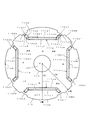
リラクタンストルクを発生させるq軸磁束は、主磁極部を挟んで隣接して配置されている補助磁極部の間の磁束通路を流れる。主磁極部を挟んで隣接して配置されている補助磁極部間をq軸磁束が流れる磁束通路は略同じであるため、以下では、主磁極部aを挟んで隣接して配置されている補助磁極部daと補助磁極部abの間の磁束通路について説明する。
図3には、主磁極部aを挟んで隣接して配置されている補助磁極部daと補助磁極部abの間を、ティース32Bから、補助磁極部abの外周面10AB、補助磁極部ab、磁石挿入孔11aより回転軸挿入孔19側(回転中心O側)の箇所、補助磁極da、補助磁極部daの外周面10DAを介してティース32Aの方向に流れるq軸磁束が矢印で示されている。なお、q軸磁束は、逆方向にも流れる。
ここで、分布巻方式を用いて固定子コイルをスロット33に収容する場合には、ティース32のティース幅T(ティース基部32aの最も狭い幅)が、補助磁極部10abの外周面10AB、補助磁極部10daの外周面10DAの周方向の長さより短くなる。このため、q軸磁束の量は、ティース32のティース幅Tによって制限される。したがって、q軸磁束を流すための磁束通路としては、ティース32のティース幅Tを有する磁束通路が確保されていればよい。
補助磁極部daと補助磁極部abの間に形成され、ティース32のティース幅Tを有する磁束通路は、図3に右下がり斜線で示す第1の領域Maである。この第1の領域Maは、簡略的には、磁石挿入孔11aの、回転軸挿入孔19側(回転中心O側)に配置されている内壁11a2に沿った線saと、線saに平行であり、線saから回転軸挿入孔19側に距離W(=ティース幅T)だけ離れた第1の境界線maとによって決定される。
同様に、補助磁極部abと補助磁極部bcの間に形成され、ティース幅Tを有する磁束通路は、磁石挿入孔11bの、回転軸挿入孔19側に配置されている内壁11b2に沿った線sbと、線sbに平行であり、線sbから回転軸挿入孔19側に距離W(=ティース幅T)だけ離れた第1の境界線mbとによって決定される第1の領域Mbである。また、補助磁極部bcと補助磁極部cdの間に形成され、ティース幅Tを有する磁束通路は、磁石挿入孔11cの、回転軸挿入孔19側に配置されている内壁11c2に沿った線scと、線scに平行であり、線scから回転軸挿入孔19側に距離W(=ティース幅T)だけ離れた第1の境界線mcとによって決定される第1の領域Mcである。また、補助磁極部cdと補助磁極部daの間に形成され、ティース幅Tを有する磁束通路は、磁石挿入孔11dの、回転軸挿入孔19側に配置されている内壁11d2に沿った線sdと、線sdに平行であり、線sdから回転軸挿入孔19側に距離W(=ティース幅T)だけ離れた第1の境界線mdによって決定される第1の領域Mdである。
したがって、回転子10に連通孔18を設ける場合、主磁極部a〜dに設けられている磁石挿入孔11a〜11dの内壁11a2〜11d2を基準として決定される第1の境界線ma〜mdと、内壁11a2〜11d2に沿った線sa〜sdにより形成される第1の領域Ma〜Mdに連通孔18を設けないことにより、例えば、第1の境界線ma〜mdより回転軸挿入孔19側の領域に連通孔18を設けることにより、q軸磁束の量の減少を抑制することができ、リラクタンストルクの低下を抑制することができる。すなわち、永久磁石電動機の効率低下を抑制することができる。
なお、第1の領域Ma〜Mdは、第1の境界線ma〜md上の領域を含まないように設定するのが好ましい。
The q-axis magnetic flux that generates the reluctance torque flows in the magnetic flux path between the auxiliary magnetic pole portions arranged adjacent to each other with the main magnetic pole portion interposed therebetween. Since the magnetic flux paths through which the q-axis magnetic flux flows between the auxiliary magnetic pole portions arranged adjacent to each other with the main magnetic pole portion interposed therebetween are substantially the same, in the following, the auxiliary arranged adjacent to each other with the main magnetic pole portion a interposed therebetween The magnetic flux path between the magnetic pole part da and the auxiliary magnetic pole part ab will be described.
In FIG. 3, between the auxiliary magnetic pole part da and the auxiliary magnetic pole part ab arranged adjacent to each other with the main magnetic pole part a interposed therebetween, from the teeth 32B, the outer peripheral surface 10AB of the auxiliary magnetic pole part ab, the auxiliary magnetic pole part ab, The q-axis magnetic flux flowing in the direction of the teeth 32A via the magnet insertion hole 11a on the rotary
Here, when the stator coil is accommodated in the slot 33 using the distributed winding method, the teeth width T of the teeth 32 (the narrowest width of the teeth base portion 32a) is the outer peripheral surface 10AB of the auxiliary magnetic pole portion 10ab, the auxiliary magnetic pole. It becomes shorter than the length of the outer peripheral surface 10DA of the part 10da in the circumferential direction. For this reason, the amount of the q-axis magnetic flux is limited by the tooth width T of the
A magnetic flux path formed between the auxiliary magnetic pole part da and the auxiliary magnetic pole part ab and having the tooth width T of the
Similarly, the magnetic flux path formed between the auxiliary magnetic pole part ab and the auxiliary magnetic pole part bc and having the teeth width T is a line along the inner wall 11b2 of the magnet insertion hole 11b arranged on the rotating
Therefore, when the communication hole 18 is provided in the
The first areas Ma to Md are preferably set so as not to include the areas on the first boundary lines ma to md.
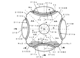
マグネットトルクを発生させるd軸磁束は、補助磁極部を挟んで隣接して配置されている主磁極部の間の磁束通路を流れる。補助磁極部を挟んで隣接して配置されている主磁極部間をd軸磁束が流れる磁束通路は略同じであるため、以下では、補助磁極部bcを挟んで隣接して配置されている主磁極部bと主磁極部cの間の磁束通路及び補助磁極部cdを挟んで隣接して配置されている主磁極部cと主磁極部dの間の磁束通路について説明する。
図4には、補助磁極部bcを挟んで隣接して配置されている主磁極部bと主磁極部cの間を、ティース32E、32F、32Gから、主磁極部cの外周面10C、主磁極部c、主磁極部cに設けられている磁石挿入孔11cに挿入されている永久磁石12c、主磁極部cに隣接する補助磁極部bc、補助磁極部bcに隣接する主磁極部bに設けられている磁石挿入孔11bに挿入されている永久磁石12b、主磁極部b、主磁極部bの外周面10Bを介してティース32C、32Dの方向に流れるd軸磁束と、補助磁極部cdを挟んで隣接して配置されている主磁極部cと主磁極部dの間を、ティース32E、32F、32Gから、主磁極部cの外周面10C、主磁極部c、主磁極部cに設けられている磁石挿入孔11cに挿入されている永久磁石12c、主磁極部cに隣接する補助磁極部cd、補助磁極部cdに隣接する主磁極部dに設けられている磁石挿入孔11dに挿入されている永久磁石12d、主磁極部d、主磁極部dの外周面10Dを介してティース32H、32Iの方向に流れるd軸磁束が矢印で示されている。d軸磁束は、主磁極部に設けられている磁石挿入孔に挿入されている永久磁石と、当該主磁極部に対して周方向両側に隣接して配置されている主磁極部に設けられている磁石挿入孔の間を流れる(図4では、永久磁石12cから流れる磁束は、永久磁石12b、12dの方向に2分される。)。なお、d軸磁束は、逆方向にも流れる。
ここで、一般的に、電磁鋼板固有の磁束密度の最大値は、永久磁石の磁束密度の最大値より小さい。このため、隣接する主磁極部に設けられている永久磁石の間を流れる磁束の量の最大値は、永久磁石から回転子に流れる磁束の量の最大値によって制限される。また、電磁鋼板を積層して形成された回転子(回転子鉄心)を流れる磁束の量の最大値は電磁鋼板の飽和磁束密度に基づいて定まる。なお、永久磁石から回転子(回転子鉄心)に流れる磁束の量の最大値は永久磁石の磁束密度(設定磁束密度)に基づいて設計される。
このため、d軸磁束を流すための磁束通路としては、回転子10(回転子鉄心11)の飽和磁束密度と永久磁石12cから回転子10(回転子鉄心11)に流れる磁束の磁束密度によって定まる磁束通路が確保されていればよい。
主磁極部cと主磁極部b及びdの間に形成され、回転子10(回転子鉄心11)の飽和磁束密度と永久磁石12cから回転子10(回転子鉄心11)に流れる磁束密度によって定まる磁束通路は、図4に右斜線で示す第2の領域Nc1、Nc2である。この第2の領域Nc1、Nc2は、簡略的に、主磁極部cに設けられている磁石挿入孔11cの内壁11c2に沿った線scと、線scと主磁極部cのd軸が交差する点Pcから周方向に隣接する主磁極部b、dの方向に延び、回転子10(回転子コア)の飽和磁束密度に対応する長さLと永久磁石12cから回転子10(回転子鉄心11)に流れる磁束の磁束密度に対応する長さHとの比(H/L)の傾きを有する第2の境界線nc1、nc2とによって決定される。なお、点Pcは、主磁極部cに設けられている永久磁石の、回転軸挿入孔19側の側面の中心点を用いるのが好ましいが、通常、永久磁石の中心が主磁極部の中心(d軸)に略一致するように永久磁石12cが主磁極部cに配置されるため、本実施の形態では、線scとd軸が交差する点を点Pcとして用いている。
同様に、主磁極部aと主磁極部b及びdの間に形成される磁束通路は、主磁極部aに設けられている磁石挿入孔11aの内壁11a2に沿った線saと、線saと主磁極部aのd軸が交差する点から周方向に隣接する主磁極部b、dの方向に延び、回転子10の飽和磁束密度と永久磁石12aから回転子10に流れる磁束の磁束密度との比(H/L)に等しい傾きを有する第2の境界線na1、na2とによって決定される第2の領域Na1、Na2である。また、主磁極部bと主磁極部a及びcの間に形成される磁束通路は、主磁極部bに設けられている磁石挿入孔11bの内壁11b2に沿った線sbと、線sbと主磁極部bのd軸が交差する点から周方向に隣接する主磁極部a、cの方向に延び、回転子10の飽和磁束密度と永久磁石12bから回転子10に流れる磁束の磁束密度との比(H/L)に等しい傾きを有する第2の境界線nb1、nb2とによって決定される第2の領域Nb1、Nb2である。また、主磁極部dと主磁極部c及びaの間に形成される磁束通路は、主磁極部dに設けられている磁石挿入孔11dの内壁11dに沿った線sdと、線sdと主磁極部dのd軸が交差する点から周方向に隣接する主磁極部c、aの方向に延び、回転子10の飽和磁束密度と永久磁石12dから回転子10に流れる磁束の磁束密度との比(H/L)に等しい傾きを有する第2の境界線nd1、nd2とによって決定される第2の領域Nd1、Nd2である。
したがって、回転子10に連通孔18を設ける場合、主磁極部a〜dに設けられている磁石挿入孔11a〜11dの内壁11a2〜11d2を基準として決定される第2の境界線na1、na2〜nd1、nd2と内壁11a2〜11d2に沿った線sa〜sdにより形成される第2の領域Na1、Na2〜Nd1、Nd2に連通孔18を設けないことにより、言い換えれば、第2の境界線na1、na2〜nd1、nd2より回転軸挿入孔19側の領域に連通孔18を設けることにより、d軸磁束の量の減少を抑制することができ、マグネットトルクの低下を抑制することができる。すなわち、永久磁石電動機の効率低下を抑制することができる。
なお、第2の領域Na1、Na2〜Nd1、Nd2は、第2の境界線na1、na2〜nd1、nd2上の領域を含まないように設定するのが好ましい。
The d-axis magnetic flux that generates the magnet torque flows in the magnetic flux path between the main magnetic pole portions arranged adjacent to each other with the auxiliary magnetic pole portion interposed therebetween. Since the magnetic flux paths through which the d-axis magnetic flux flows between the main magnetic pole portions arranged adjacent to each other with the auxiliary magnetic pole portion interposed therebetween are substantially the same, hereinafter, the main magnetic pole portions arranged adjacent to each other with the auxiliary magnetic pole portion bc interposed therebetween. A magnetic flux path between the magnetic pole part b and the main magnetic pole part c and a magnetic flux path between the main magnetic pole part c and the main magnetic pole part d arranged adjacent to each other with the auxiliary magnetic pole part cd interposed therebetween will be described.
In FIG. 4, between the main magnetic pole part b and the main magnetic pole part c arranged adjacent to each other with the auxiliary magnetic pole part bc interposed therebetween, from the teeth 32E, 32F, and 32G, the outer peripheral surface 10C of the main magnetic pole part c, the main magnetic pole part c, The magnetic pole part c, the permanent magnet 12c inserted in the magnet insertion hole 11c provided in the main magnetic pole part c, the auxiliary magnetic pole part bc adjacent to the main magnetic pole part c, and the main magnetic pole part b adjacent to the auxiliary magnetic pole part bc The d-axis magnetic flux flowing in the direction of the teeth 32C and 32D via the permanent magnet 12b, the main magnetic pole part b, and the outer
Here, generally, the maximum value of the magnetic flux density specific to the electromagnetic steel sheet is smaller than the maximum value of the magnetic flux density of the permanent magnet. For this reason, the maximum value of the amount of magnetic flux flowing between the permanent magnets provided in the adjacent main magnetic pole portions is limited by the maximum value of the amount of magnetic flux flowing from the permanent magnet to the rotor. Further, the maximum value of the amount of magnetic flux flowing through a rotor (rotor core) formed by laminating electromagnetic steel sheets is determined based on the saturation magnetic flux density of the electromagnetic steel sheets. The maximum value of the amount of magnetic flux flowing from the permanent magnet to the rotor (rotor core) is designed based on the magnetic flux density (set magnetic flux density) of the permanent magnet.
For this reason, the magnetic flux path for flowing the d-axis magnetic flux is determined by the saturation magnetic flux density of the rotor 10 (rotor core 11) and the magnetic flux density of the magnetic flux flowing from the permanent magnet 12c to the rotor 10 (rotor core 11). What is necessary is just to ensure the magnetic flux path.
It is formed between the main magnetic pole part c and the main magnetic pole parts b and d, and is determined by the saturation magnetic flux density of the rotor 10 (rotor core 11) and the magnetic flux density flowing from the permanent magnet 12c to the rotor 10 (rotor core 11). The magnetic flux paths are second regions Nc1 and Nc2 indicated by right oblique lines in FIG. In the second regions Nc1 and Nc2, the line sc along the inner wall 11c2 of the magnet insertion hole 11c provided in the main magnetic pole part c, and the line sc and the d axis of the main magnetic pole part c intersect each other. From the point Pc in the direction of the main magnetic pole portions b and d adjacent in the circumferential direction, the length L corresponding to the saturation magnetic flux density of the rotor 10 (rotor core) and the permanent magnet 12c to the rotor 10 (
Similarly, the magnetic flux path formed between the main magnetic pole part a and the main magnetic pole parts b and d includes a line sa and a line sa along the inner wall 11a2 of the magnet insertion hole 11a provided in the main magnetic pole part a. The saturation magnetic flux density of the
Therefore, when the communication hole 18 is provided in the
The second regions Na1, Na2 to Nd1, and Nd2 are preferably set so as not to include the regions on the second boundary lines na1, na2 to nd1, and nd2.
永久磁石電動機の永久磁石としてはフェライト磁石や希土類磁石等の種々の磁石を用いることができるが、永久磁石電動機を圧縮機駆動用電動機として用いる場合には、温度が高くなっても磁束密度の低下が低い希土類磁石が用いられる。また、希土類磁石の中でも、永久磁石電動機の効率向上の観点からネオジウム磁石が用いられる。一般的には、ネオジウム磁石の磁束密度(設定磁束密度)は、約1.1テスラ〜1.4テスラの範囲に設定される。
ここで、永久磁石電動機を製造する際、永久磁石から回転子(回転子鉄心)に流れる磁束の磁束密度が、設定磁束密度より低い磁束密度となるように設計される。例えば、永久磁石から回転子10(回転子鉄心11)に約0.9テスラの磁束密度(設計磁束密度)の磁束が流れるように設計される。
また、回転子を構成する電磁鋼板の飽和磁束密度は、一般的に、約1.8テスラである。
この場合、前述した、回転子10の飽和磁束密度に対応する長さLと永久磁石から回転子(回転子鉄心)に流れる磁束の磁束密度に対応する長さHとの比(H/L)は、(H/L=0.9/1.8=1/2)となる。すなわち、主磁極部a〜dに設けられている磁石挿入孔11a〜11dの内壁11a2〜11d2に沿った線sa〜sdと、線sa〜sdと主磁極部a〜dのd軸が交差する点から周方向両側に隣接する主磁極部の方向に延び、傾きが略0.5である第2の境界線na1、na2〜nd1、nd2とによって決定される第2の領域Na1、Na2〜Nd1、Nd2が形成される。
As the permanent magnet of the permanent magnet motor, various magnets such as ferrite magnets and rare earth magnets can be used. Rare earth magnets are used. Among rare earth magnets, neodymium magnets are used from the viewpoint of improving the efficiency of permanent magnet motors. Generally, the magnetic flux density (set magnetic flux density) of a neodymium magnet is set in the range of about 1.1 Tesla to 1.4 Tesla.
Here, when the permanent magnet motor is manufactured, the magnetic flux density of the magnetic flux flowing from the permanent magnet to the rotor (rotor core) is designed to be lower than the set magnetic flux density. For example, it is designed such that a magnetic flux having a magnetic flux density (design magnetic flux density) of about 0.9 Tesla flows from a permanent magnet to the rotor 10 (rotor core 11).
The saturation magnetic flux density of the electrical steel sheet constituting the rotor is generally about 1.8 Tesla.
In this case, the ratio (H / L) between the length L corresponding to the saturation magnetic flux density of the
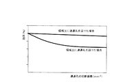
連通孔18を、図5に示す回転子10の領域X、すなわち、第1の境界線ma〜mdと、磁石挿入孔11a〜11dの内壁11a2〜11d2に沿った線sa〜sdとにより形成される第1の領域Ma〜Md(図3参照)と、第2の境界線na1、na2〜nd1、nd2と磁石挿入孔11a〜11dの内壁11a2〜11d2に沿った線sa〜sdとにより形成される第2の領域Na1、Na2〜Nd1、Nd2(図4参照)に設けない場合、例えば、第1の境界線ma〜mdより回転軸挿入孔19側の領域であって、第2の境界線na1、na2〜nd1、nd2より回転軸挿入孔19側の領域Yに設けた場合の永久磁石電動機の効率について検討した結果を図6に示す。図6において、横軸は連通孔の総断面積を示し、縦軸は永久磁石電動機の効率を示している。なお、図6は、同じ大きさの固定子及び回転子を用い、連通孔の配置位置、数、断面積を変えた場合の「連通孔の総面積−効率」グラフを示している。
図6に示されているように、領域Xに連通孔18を設けないで領域Yに連通孔18を設けた場合には、連通孔18の総断面積が増大しても永久磁石電動機の効率は殆ど低下していない。一方、領域Xに連通孔18を設けた場合には、連通孔18の総断面積の増加とともに永久磁石電動機の効率が低下している。
したがって、図5に示す、各主磁極部a〜dの磁石収容孔11a〜11dの内壁11a2〜11d2に基づいて決定される第1の領域Ma〜Md(図3参照)と第2の領域Na1、Na2〜Nd1、Nd2(図4参照)を含む領域Xを確保した状態で、領域Xを除いた領域、例えば、第1の境界線ma〜mdより回転軸挿入孔19側の領域であって、第2の境界線na1、na2〜nd1、nd2より回転軸挿入孔19側の領域Yに連通孔18を設けることにより、永久磁石電動機の効率を低下させることなく、回転子10に連通孔18を設けることができる。
The communication hole 18 is formed by the region X of the
As shown in FIG. 6, when the communication hole 18 is provided in the region Y without providing the communication hole 18 in the region X, the efficiency of the permanent magnet motor is increased even if the total cross-sectional area of the communication hole 18 is increased. Has hardly decreased. On the other hand, when the communication hole 18 is provided in the region X, the efficiency of the permanent magnet motor decreases as the total cross-sectional area of the communication hole 18 increases.
Accordingly, the first regions Ma to Md (see FIG. 3) and the second region Na1 determined based on the inner walls 11a2 to 11d2 of the magnet housing holes 11a to 11d of the main magnetic pole portions a to d shown in FIG. In a state where the region X including Na2 to Nd1 and Nd2 (see FIG. 4) is secured, the region excluding the region X, for example, the region closer to the rotary
前述したように、噴霧状の潤滑油の吐出による熱交換器での熱交換効率の低下を防止するためには、冷却媒体通路として用いられる連通孔の総断面積を大きくする必要がある。冷却媒体通路として用いる連通孔は、永久磁石電動機の固定子及び回転子のいずれに設けられていてもよい。
本実施の形態では、固定子30に連通孔34を設けるとともに、回転子10に連通孔18を設けている。
これにより、噴霧状の潤滑油の吐出による熱交換器での熱交換効率の低下を防止するために必要な連通孔の総断面積を確保する際に、固定子30に設けられる連通孔34の総断面積を低減することができる。
また、本実施の形態では、ティース幅、回転子の飽和磁束密度、永久磁石の磁束密度(設計磁束密度)によって決定される領域Xを除く領域Y、すなわち、磁石挿入孔11a〜11dの内壁11a2〜11d2より回転軸挿入孔19側に設定された第1の境界線ma〜md及び第2の境界線na1、na2〜nd1、nd2より回転軸挿入孔19側の領域Yに連通孔18を設けている。これにより、永久磁石電動機の効率を低下させることなく、回転子10に連通孔18を設けることができる。
このように、本実施の形態では、固定子に設ける連通孔34の総断面積を低減して永久磁石電動機の効率を向上させる構成と、第1の境界線ma〜mdと第2の境界線na1、na2〜nd1、nd2とによって決定される領域Xに連通孔18を設けない構成(領域Yに連通孔18を設ける構成)、すなわち、永久磁石電動機の効率を低下させることなく回転子10に連通孔18を設けることができる構成を組み合わせて用いることができる。これにより、永久磁石電動機の効率を向上させることができる。
As described above, in order to prevent the heat exchange efficiency in the heat exchanger from being lowered due to the discharge of the spray-like lubricating oil, it is necessary to increase the total cross-sectional area of the communication holes used as the cooling medium passage. The communication hole used as the cooling medium passage may be provided in either the stator or the rotor of the permanent magnet motor.
In the present embodiment, the communication hole 34 is provided in the
Accordingly, when securing the total cross-sectional area of the communication holes necessary to prevent the heat exchange efficiency in the heat exchanger from being lowered due to the discharge of the spray-like lubricating oil, the communication holes 34 provided in the
In the present embodiment, the region Y excluding the region X determined by the teeth width, the saturation magnetic flux density of the rotor, and the magnetic flux density (design magnetic flux density) of the permanent magnet, that is, the inner wall 11a2 of the magnet insertion holes 11a to 11d. A communication hole 18 is provided in a region Y closer to the rotary
Thus, in this Embodiment, the structure which reduces the total cross-sectional area of the communicating hole 34 provided in a stator and improves the efficiency of a permanent magnet motor, 1st boundary line ma-md, and 2nd boundary line A configuration in which the communication hole 18 is not provided in the region X determined by na1, na2 to nd1, and nd2 (a configuration in which the communication hole 18 is provided in the region Y), that is, in the
また、回転軸20を回転軸挿入孔19に挿入する時には、回転子10の外径を大きくする応力が永久磁石12a〜12dに加わる。特に、焼きばめ方法を用いて回転軸20を回転軸挿入孔19に挿入する時には、回転子10(回転子鉄心11)の熱膨張率と永久磁石12a〜12dの熱膨張率と違いによる応力も永久磁石12a〜12dに加わる。このため、回転軸20を回転軸挿入孔19に挿入する時に、永久磁石12a〜12dが割れたり、欠けたりする虞がある。
本実施の形態では、磁石挿入孔11a〜11dと回転軸挿入孔19の間に連通孔18が設けられている。これにより、回転子10の外径を大きくする応力が連通孔18で吸収される。また、焼きばめ方法を用いて回転軸20を回転軸挿入孔19に挿入する時には、連通孔18によって、永久磁石12a〜12dへの熱の伝達が抑制される。これにより、永久磁石12a〜12dの応力による割れや欠けを防止することができる。
Further, when the
In the present embodiment, a communication hole 18 is provided between the magnet insertion holes 11 a to 11 d and the rotary
以上の説明では、簡略的に、磁石挿入孔11a〜11dに対応する第1の領域Ma〜Mdを、第1の境界線ma〜mdと内壁11a2〜11d2に沿った線sa〜sdにより形成し、磁石挿入孔11a〜11dに対応する第2の領域Na1、Na2〜Nd1、Nd2を、第2の境界線na1、na2〜nd1、nd2と内壁11a2〜11d2に沿った線sa〜sdにより形成したが、第1の領域Ma〜Md及び第2の領域Na1、Na2〜Nd1、Nd2をより正確に形成することもできる。例えば、図3に示すように、磁石挿入孔11aに対応する第1の領域Maを、第1の境界線maと、内壁11a2に沿った線saと、内側側壁11a5、11a6に沿った線sa2、sa3によって形成し、また、図4に示すように、磁石挿入孔11cに対応する第2の領域Nc1、Nc2を、第2の境界線nc1、nc2と、内壁11c2に沿った線scと、内側側壁11c5、11c6に沿った線sc2、sc3により形成することもできる(図3、図4に右下がり斜線で示す領域)。この場合には、より効果的に効率低下を抑制することができる第1の領域及び第2の領域を設定することができる。この場合、磁石挿入孔11b〜11dに対応する第1の領域Mb〜Md、第2の領域Nb1、Nb2〜Nd1、Nd2も同様に設定する。
また、第1の領域Ma〜Mdと第2の領域Na1、Na2〜Nd1、Nd2に連通孔18を設けない態様としては、第1の境界線ma〜mdより回転軸挿入孔19側の領域であって、第2の境界線na1、na2〜nd1、nd2より回転軸挿入孔19側の領域Yに連通孔を設ける態様や、磁石挿入孔11a〜11dの外壁11a1〜11d1より回転子10の外周面側の領域に連通孔を設ける態様が含まれる。なお、マグネットトルクを発生させる磁束を流す通路の面積を確保する観点からは、第1の境界線ma〜mdより回転軸挿入孔19側の領域であって、第2の境界線na1、na2〜nd1、nd2より回転軸挿入孔19側の領域Yに連通孔を設ける態様を用いるのが好ましい。
このような構成は、以下の各実施の形態でも用いることができる。
In the above description, the first regions Ma to Md corresponding to the magnet insertion holes 11a to 11d are simply formed by the first boundary lines ma to md and the lines sa to sd along the inner walls 11a2 to 11d2. The second regions Na1, Na2 to Nd1, and Nd2 corresponding to the magnet insertion holes 11a to 11d are formed by the second boundary lines na1, na2 to nd1, and nd2 and the lines sa to sd along the inner walls 11a2 to 11d2. However, the first regions Ma to Md and the second regions Na1, Na2 to Nd1, and Nd2 can be formed more accurately. For example, as shown in FIG. 3, the first region Ma corresponding to the magnet insertion hole 11a is divided into a first boundary line ma, a line sa along the inner wall 11a2, and a line sa2 along the inner side walls 11a5 and 11a6. , Sa3, and as shown in FIG. 4, second regions Nc1 and Nc2 corresponding to the magnet insertion holes 11c are divided into second boundary lines nc1 and nc2, and a line sc along the inner wall 11c2. It can also be formed by lines sc2 and sc3 along the inner side walls 11c5 and 11c6 (regions indicated by slanting right-down lines in FIGS. 3 and 4). In this case, it is possible to set the first region and the second region that can more effectively suppress the decrease in efficiency. In this case, the first regions Mb to Md and the second regions Nb1, Nb2 to Nd1, and Nd2 corresponding to the magnet insertion holes 11b to 11d are set similarly.
Moreover, as an aspect which does not provide the communication hole 18 in 1st area | region Ma-Md and 2nd area | region Na1, Na2-Nd1, Nd2, in the area | region of the rotating
Such a configuration can also be used in the following embodiments.
第1の実施の形態では、断面形状が直線形状を有する1層の磁石挿入孔に、断面形状が長方形形状を有する永久磁石を挿入したが、磁石挿入孔や永久磁石の形状や数等は適宜変更可能である。以下に、他の実施の形態を説明する。
なお、以下の説明では、固定子は、図1及び図2に示した固定子と同様の固定子を用いているため、説明を省略する。また、磁石挿入孔に永久磁石を位置決めするための位置決め突部を省略して説明しているが、位置決め突部を設けることもできる。
(第2の実施の形態)
第2の実施の形態を、図7〜9に示す。第2の実施の形態は、軸方向に直角な断面形状が台形形状を有する1層の磁石挿入孔に、軸方向に直角な断面形状が長方形形状方を有する永久磁石を複数挿入したものである。
本実施の形態では、回転子110には、各主磁極部a〜dには、軸方向に直角な断面形状が、外周方向に凹状(中心方向に突状)に形成されている台形形状を有している磁石挿入孔111a〜111dが1層設けられている。
磁石挿入孔111aは、外壁111a1、内壁111a2、外側側壁111a3、111a4、内側側壁111a5、111a6、端壁111a7、111a8により構成されている。また、磁石挿入孔111aには、断面形状が長方形形状を有する永久磁石112a1、112a2、112a3が挿入されている。他の磁石挿入孔111b〜111dは、磁石挿入孔111aと同様の構成である。
また、第1の実施の形態と同様に、回転子110の外周面には、磁石挿入孔111a〜111dの端壁に対向する箇所に、切欠部110a1、110a2〜110d1、110d2が形成されている。これにより、回転子110(回転子鉄心111)の外周面は、主磁極部a〜dに対応する外周面110A〜110D、補助磁極部ab〜daに対応する外周面110AB〜110DAにより構成されている。
In the first embodiment, a permanent magnet having a rectangular cross-sectional shape is inserted into a single layer magnet insertion hole having a linear cross-sectional shape. However, the shape and number of the magnet insertion holes and permanent magnets are appropriately determined. It can be changed. Other embodiments will be described below.
In the following description, a stator similar to the stator shown in FIGS. 1 and 2 is used as the stator, and thus description thereof is omitted. Moreover, although the positioning protrusion for positioning a permanent magnet in a magnet insertion hole is abbreviate | omitted and demonstrated, a positioning protrusion can also be provided.
(Second Embodiment)
A second embodiment is shown in FIGS. In the second embodiment, a plurality of permanent magnets having a rectangular cross section perpendicular to the axial direction are inserted into a single layer magnet insertion hole having a trapezoidal cross section perpendicular to the axial direction. .
In the present embodiment, the
The magnet insertion hole 111a includes an outer wall 111a1, an inner wall 111a2, outer side walls 111a3 and 111a4, inner side walls 111a5 and 111a6, and end walls 111a7 and 111a8. In addition, permanent magnets 112a1, 112a2, and 112a3 having a rectangular cross section are inserted into the magnet insertion hole 111a. The other magnet insertion holes 111b to 111d have the same configuration as the magnet insertion hole 111a.
Similarly to the first embodiment, notches 110 a 1, 110 a 2 to 110
本実施の形態では、図8に示すように、磁石挿入孔111aの内壁111a2と、内壁111a2に沿った線saと平行であり、線saから回転軸挿入孔119側(回転中心O)に距離W(=ティース幅T)だけ離れた第1の境界線maとによって、磁石挿入孔111aに対応する第1の領域Maが形成されている。なお、図8に図示を省略しているが、磁石挿入孔111b〜111dの内壁111b2〜111d2と、第1の境界線maと同様の第1の境界線mb〜md(図9参照)とによって、磁石挿入孔111b〜111dに対応する第1の領域Mb〜Mdが形成されている。
また、図8に示すように、磁石挿入孔111cの内壁111c2と、内壁111c2に沿った線scと主磁極部cのd軸が交差する点Pcから、隣接する主磁極部b、dの方向に延び、回転子110(回転子鉄心111)の飽和磁束密度と永久磁石112c1から回転子110(回転子鉄心111)に流れる磁束の磁束密度の比を傾きとする第2の境界線nc1、nc2とによって、磁石挿入孔111cに対応する第2の領域Nc1、Nc2が形成されている。なお、図8に図示を省略しているが、磁石挿入孔111a、111b、111dの内壁111a2、111b2、111d2と、第2の境界線nc1、nc2と同様の第2の境界線na1、na2、nb1、nb2、nd1、nd2(図9参照)とによって、磁石挿入孔111a、111b、111dに対応する第2の領域Na1、Na2、Nb1、Nb2、Nd1、Nd2が形成されている。
そして、領域X(例えば、第1の境界線ma〜md(図9参照)と磁石挿入孔111a〜111dの内壁111a2〜111d2に沿った線sa〜sdにより形成される第1の領域Ma〜Md(図示省略)と、第2の境界線na1、na2〜nd1、nd2(図9参照)と磁石挿入孔111a〜111dの内壁111a2〜111d2に沿った線sa〜sdにより形成される第2の領域Na1、Na2〜Nd1、Nd2)に連通孔を設けないで、領域Y(第1の境界線ma〜mdより回転軸挿入孔119側の領域であって、第2の境界線na1、na2〜nd1、nd2より回転軸挿入孔119側の領域)に連通孔を設けている(図9参照)。
本実施の形態も、第1の実施の形態と同様の効果を有している。
In the present embodiment, as shown in FIG. 8, the inner wall 111a2 of the magnet insertion hole 111a is parallel to the line sa along the inner wall 111a2, and the distance from the line sa to the rotation
Further, as shown in FIG. 8, the direction from the inner wall 111c2 of the magnet insertion hole 111c and the point Pc where the line sc along the inner wall 111c2 intersects the d axis of the main magnetic pole part c to the adjacent main magnetic pole parts b and d. The second boundary lines nc1 and nc2 are inclined with a ratio of the saturation magnetic flux density of the rotor 110 (rotor core 111) and the magnetic flux density of the magnetic flux flowing from the permanent magnet 112c1 to the rotor 110 (rotor core 111). As a result, second regions Nc1 and Nc2 corresponding to the magnet insertion holes 111c are formed. Although not shown in FIG. 8, the inner walls 111a2, 111b2, 111d2 of the magnet insertion holes 111a, 111b, 111d and the second boundary lines na1, na2, similar to the second boundary lines nc1, nc2, Second regions Na1, Na2, Nb1, Nb2, Nd1, and Nd2 corresponding to the magnet insertion holes 111a, 111b, and 111d are formed by nb1, nb2, nd1, and nd2 (see FIG. 9).
And 1st area | region Ma-Md formed by area | region X (For example, 1st boundary line ma-md (refer FIG. 9) and line sa-sd along inner wall 111a2-111d2 of magnet insertion hole 111a-111d). (Not shown), and second regions formed by second boundary lines na1, na2-nd1, nd2 (see FIG. 9) and lines sa-sd along inner walls 111a2-111d2 of magnet insertion holes 111a-111d No communication hole is provided in Na1, Na2-Nd1, Nd2), and the region Y (the region closer to the rotation
This embodiment also has the same effect as the first embodiment.
以上の説明では、簡略的に、第1の領域Ma〜Mdを、第1の境界線ma〜mdと内壁111a2〜111d2に沿った線sa〜sdにより形成し、第2の領域Na1、Na2〜Nd1、Nd2を、第2の境界線na1、na2〜nd1、nd2と内壁111a2〜111d2に沿った線sa〜sdにより形成したが、第1の領域Ma〜Md及び第2の領域Na1、Na2〜Nd1、Nd2をより正確に形成することもできる。例えば、図8に示すように、第1の領域Maを、第1の境界線maと、内壁111a2に沿った線saと、内側側壁111a5、111a6に沿った線sa2、sa3によって形成し、第2の領域Nc1、Nc2を、第2の境界線nc1、nc2と、内壁111c2に沿った線scと、内側側壁111c5、11c6に沿った線sc2、sc3により形成することもできる(図8に斜線で示す領域)。この場合、第1の領域Mb〜Md、第2の領域Na1、Na2、Nb1、Nb2、Nd1、Nd2も同様に設定する。
これにより、より効果的に効率低下を抑制することができる第1の領域及び第2の領域を形成することができる。
In the above description, the first regions Ma to Md are simply formed by the lines sa to sd along the first boundary lines ma to md and the inner walls 111a2 to 111d2, and the second regions Na1, Na2 to Nad are formed. Nd1 and Nd2 are formed by the second boundary lines na1, na2 to nd1, and nd2 and lines sa to sd along the inner walls 111a2 to 111d2, but the first regions Ma to Md and the second regions Na1, Na2 Nd1 and Nd2 can also be formed more accurately. For example, as shown in FIG. 8, the first region Ma is formed by a first boundary line ma, a line sa along the inner wall 111a2, and lines sa2 and sa3 along the inner side walls 111a5 and 111a6. The second regions Nc1 and Nc2 can be formed by the second boundary lines nc1 and nc2, the line sc along the inner wall 111c2, and the lines sc2 and sc3 along the inner side walls 111c5 and 11c6 (the hatched lines in FIG. 8). Area). In this case, the first regions Mb to Md and the second regions Na1, Na2, Nb1, Nb2, Nd1, and Nd2 are set similarly.
Thereby, the 1st area | region and 2nd area | region which can suppress an efficiency fall more effectively can be formed.
(第3の実施の形態)
第3の実施の形態を図10〜12に示す。第3の実施の形態は、軸方向に直角な断面形状が、外周方向に凹状(中心方向に突状)に形成されているV字形状を有する1層の磁石挿入孔に、軸方向に直角な断面形状が長方形形状方を有する永久磁石を複数挿入したものである。
本実施の形態では、回転子210には、各主磁極部a〜dには、軸方向に直角な断面形状が、外周方向に凹状に形成されているV字形状を有している磁石挿入孔211a〜211dが1層設けられている。
磁石挿入孔211aは、外壁211a1、211a2、内壁211a3、211a4、端壁211a5、211a6により構成されている。また、磁石挿入孔211aには、断面形状が長方形形状を有する永久磁石212a1、212a2が挿入されている。他の磁石挿入孔211b〜211dは、磁石挿入孔211aと同様の構成である。
また、第1の実施の形態と同様に、回転子210(回転子鉄心211)の外周面には、磁石挿入孔211a〜211dの端壁に対向する箇所に、切欠部210a1、210a2〜210d1、210d2が形成されている。これにより、回転子210の外周面は、主磁極部a〜dに対応する外周面210A〜210D、補助磁極部ab〜daに対応する外周面210AB〜210DAにより構成されている。
(Third embodiment)
A third embodiment is shown in FIGS. In the third embodiment, the cross-sectional shape perpendicular to the axial direction is perpendicular to the axial direction in a single-layer magnet insertion hole having a V-shape that is formed in a concave shape (projecting in the central direction) in the outer circumferential direction. A plurality of permanent magnets having a rectangular cross-sectional shape are inserted.
In the present embodiment, in the
The magnet insertion hole 211a includes outer walls 211a1, 211a2, inner walls 211a3, 211a4, and end walls 211a5, 211a6. In addition, permanent magnets 212a1 and 212a2 having a rectangular cross section are inserted into the magnet insertion hole 211a. The other magnet insertion holes 211b to 211d have the same configuration as the magnet insertion hole 211a.
Similarly to the first embodiment, on the outer peripheral surface of the rotor 210 (rotor core 211), notches 210a1, 210a2 to 210d1, at positions facing the end walls of the magnet insertion holes 211a to 211d, 210d2 is formed. Thereby, the outer peripheral surface of the
本実施の形態では、図11に示すように、磁石挿入孔211aの内壁211a3に沿った線sa1と、線sa1に平行であり、線sa1から回転軸挿入孔219側(回転中心O)に距離W(=ティース幅T)だけ離れた第1の境界線ma1とによって、また、磁石挿入孔211aの内壁211a4に沿った線sa2と、線sa2に平行であり、線sa2から回転軸挿入孔219側(回転中心O)に距離W(=ティース幅T)だけ離れた第1の境界線ma2とによって、磁石挿入孔211aに対応する第1の領域Ma1、Ma2が形成されている。なお、図11に図示を省略しているが、磁石挿入孔211b〜211dの内壁211b3、211b4〜211d3、211d4と、第1の境界線ma1、ma2と同様の第1の境界線mb1、mb2〜md1、md2(図12参照)とによって、磁石挿入孔211b〜211dに対応する第1の領域Mb1、Mb2〜Md1、Md2が形成されている。
また、図11に示すように、磁石挿入孔211cの内壁211c3に沿った線sc1及び磁石挿入孔211cの内壁211c4に沿った線sc2(磁石挿入孔の内壁に沿った線)と、線sc1及び線sc2と主磁極部cのd軸が交差する点Pcから、隣接する主磁極部b、dの方向に延び、回転子210(回転子鉄心211)の飽和磁束密度と永久磁石212c1、212c2から回転子210(回転子鉄心211)に流れる磁束の磁束密度の比を傾きとする第2の境界線nc1、nc2とによって、磁石挿入孔211cに対応する第2の領域Nc1、Nc2が形成されている。なお、図11に図示を省略しているが、磁石挿入孔211a、211b、211dの内壁211a3、211a4、211b3、211b4、211d3、211d4と、第2の境界線nc1、nc2と同様の第2の境界線na1、na2、nb1、nb2、nd1、nd2(図12参照)とによって、磁石挿入孔211a、211b、211dに対応する第2の領域Na1、Na2、Nb1、Nb2、Nd1、Nd2が形成されている。
そして、領域X(例えば、第1の境界線ma1、ma2〜md1、md2と磁石挿入孔211aの内壁211a3、211a4〜211d3、211d4に沿った線sa1、sa2〜sd1、sd2により形成される第1の領域Ma1、Ma2〜Md1、Md2と、第2の境界線na1、na2〜nd1、nd2と磁石挿入孔211a〜211dの内壁211a3、211a4〜211d3、211d4に沿った線sa1、sa2〜sd1、sd2により形成される第2の領域Na1、Na2〜Nd1、Nd2)に設けないで、領域Y(第1の境界線ma1、ma2〜md1、md2より回転軸挿入孔219側の領域であって、第2の境界線na1、na2〜nd1、nd2より回転軸挿入孔219側の領域)に連通孔を設けている(図12参照)。
本実施の形態も、第1の実施の形態と同様の効果を有している。
In the present embodiment, as shown in FIG. 11, the line sa1 along the inner wall 211a3 of the magnet insertion hole 211a is parallel to the line sa1, and the distance from the line sa1 to the rotation shaft insertion hole 219 side (rotation center O). The first boundary line ma1 separated by W (= the teeth width T), the line sa2 along the inner wall 211a4 of the magnet insertion hole 211a, and parallel to the line sa2, and from the line sa2 to the rotation shaft insertion hole 219 First regions Ma1 and Ma2 corresponding to the magnet insertion hole 211a are formed by the first boundary line ma2 that is separated by a distance W (= tooth width T) on the side (rotation center O). Although not shown in FIG. 11, the inner walls 211b3, 211b4 to 211d3, and 211d4 of the magnet insertion holes 211b to 211d and the first boundary lines mb1 and mb2 similar to the first boundary lines ma1 and ma2 are used. First regions Mb1, Mb2 to Md1, and Md2 corresponding to the magnet insertion holes 211b to 211d are formed by md1 and md2 (see FIG. 12).
Further, as shown in FIG. 11, a line sc1 along the inner wall 211c3 of the magnet insertion hole 211c, a line sc2 (a line along the inner wall of the magnet insertion hole) along the inner wall 211c4 of the magnet insertion hole 211c, a line sc1 and From the point Pc where the line sc2 and the d axis of the main magnetic pole part c intersect, it extends in the direction of the adjacent main magnetic pole parts b, d, and from the saturation magnetic flux density of the rotor 210 (rotor core 211) and the permanent magnets 212c1, 212c2. Second regions Nc1 and Nc2 corresponding to the magnet insertion hole 211c are formed by the second boundary lines nc1 and nc2 having an inclination of the ratio of the magnetic flux density of the magnetic flux flowing through the rotor 210 (rotor core 211). Yes. Although not shown in FIG. 11, the inner walls 211a3, 211a4, 211b3, 211b4, 211d3, and 211d4 of the magnet insertion holes 211a, 211b, and 211d and the second boundary lines nc1 and nc2 are the same as the second boundary lines nc1 and nc2. The boundary areas na1, na2, nb1, nb2, nd1, nd2 (see FIG. 12) form second regions Na1, Na2, Nb1, Nb2, Nd1, Nd2 corresponding to the magnet insertion holes 211a, 211b, 211d. ing.
Then, the region X (for example, the first boundary lines ma1, ma2 to md1, and md2 and the first lines formed by the lines sa1, sa2 to sd1, and sd2 along the inner walls 211a3, 211a4 to 211d3, and 211d4 of the magnet insertion hole 211a. Area Ma1, Ma2-Md1, Md2 and second boundary lines na1, na2-nd1, nd2 and lines sa1, sa2-sd1, sd2 along inner walls 211a3, 211a4-211d3, 211d4 of magnet insertion holes 211a-211d. Without being provided in the second region Na1, Na2-Nd1, Nd2) formed by the region Y (the first boundary lines ma1, ma2-md1, md2 are regions closer to the rotation shaft insertion hole 219), The communication holes are provided in the boundary lines na1, na2 to nd1, and nd2 (regions closer to the rotation shaft insertion hole 219) (FIG. 12). Irradiation).
This embodiment also has the same effect as the first embodiment.
(第4の実施の形態)
第4の実施の形態を、図13〜15に示す。第4の実施の形態は、軸方向に直角な断面形状が、外周方向に凹状(中心方向に突状)に形成されている曲線形状を有する1層の磁石挿入孔に、軸方向に直角な断面形状が曲線形状を有する永久磁石を挿入したものである。
本実施の形態では、回転子310には、各主磁極部a〜dに、軸方向に直角な断面形状が、外周方向に凹状に形成されている曲線形状を有している磁石挿入孔311a〜311dが1層設けられている。
磁石挿入孔311aは、外壁311a1、内壁311a2、端壁311a3、311a4により構成されている。また、磁石挿入孔311aには、断面形状が曲線形状を有する永久磁石312aが挿入されている。
また、第1の実施の形態と同様に、回転子310(回転子鉄心311)の外周面には、磁石挿入孔311a〜311dの端壁に対向する箇所に、切欠部310a1、310a2〜310d1、310d2が形成されている。これにより、回転子310の外周面は、主磁極部a〜dに対応する外周面310A〜310D、補助磁極部ab〜daに対応する外周面310AB〜310DAにより構成されている。
(Fourth embodiment)
A fourth embodiment is shown in FIGS. In the fourth embodiment, the cross-sectional shape perpendicular to the axial direction is perpendicular to the axial direction in a single-layer magnet insertion hole having a curved shape formed in a concave shape (projecting shape in the central direction) in the outer circumferential direction. A permanent magnet having a curved cross-sectional shape is inserted.
In the present embodiment, the
The magnet insertion hole 311a includes an outer wall 311a1, an inner wall 311a2, and end walls 311a3 and 311a4. A permanent magnet 312a having a curved cross section is inserted into the magnet insertion hole 311a.
Similarly to the first embodiment, the outer peripheral surface of the rotor 310 (rotor core 311) is provided with notches 310a1, 310a2-310d1, at locations facing the end walls of the magnet insertion holes 311a-311d, 310d2 is formed. Thereby, the outer peripheral surface of the
本実施の形態では、磁石挿入孔311aの内壁311a2に沿った線saと平行であり、線saから回転軸挿入孔319側(回転中心O)に距離W(=ティース幅T)だけ離れた線を第1の境界線maとしている(図14参照)。
また、磁石挿入孔311cの内壁311c2に沿った線scと主磁極部cのd軸が交差する点Pcから、隣接する主磁極部の方向に延び、回転子310(回転子鉄心)の飽和磁束密度と永久磁石312cから回転子310(回転子鉄心311)に流れる磁束の磁束密度の比を傾きとする線を第2の境界線nc1、nc2としている(図14参照)。本実施の形態では、接線の方向(1次微分値のベクトル方向)が、内壁311c2に沿った線scの接線の方向(1次微分値のベクトル方向)に対して、回転子310の飽和磁束密度に対応する長さLと永久磁石312cの磁束密度に対応する長さHとの比に対応する傾きを有するように第2の境界線nc1、nc2を決定する。
本実施の形態では、図14に示すように、磁石挿入孔311aの内壁311a2に沿った線saと、線saに平行であり、線saから回転軸挿入孔319側(回転中心O)に距離W(=ティース幅T)だけ離れた第1の境界線maとによって、磁石挿入孔311aに対応する第1の領域Maが形成されている。なお、図14に図示を省略しているが、磁石挿入孔311b〜311dの内壁311b2〜311d2と、第1の境界線maと同様の第1の境界線mb〜md(図15参照)とによって、磁石挿入孔311b〜311dに対応する第1の領域Mb〜Mdが形成されている。
また、図14に示すように、磁石挿入孔311cの内壁311c2に沿った線scと主磁極部cのd軸が交差する点Pcから、隣接する主磁極部b、dの方向に延び、回転子310(回転子鉄心311)の飽和磁束密度と永久磁石312cから回転子310(回転子鉄心311)に流れる磁束の磁束密度の比を傾きとする第2の境界線nc1、nc2とによって、磁石挿入孔311cに対応する第2の領域Nc1、Nc2が形成されている。本実施の形態では、接線の方向(1次微分値のベクトル方向)が、内壁311c2に沿った線scの接線の方向(1次微分値のベクトル方向)に対して、回転子310の飽和磁束密度に対応する長さLと永久磁石312cの磁束密度に対応する長さHとの比に対応する傾きを有するように第2の境界線nc1、nc2を決定する。なお、図14に図示を省略しているが、磁石挿入孔311a、311b、311dの内壁311a2、311b2、311d2と、第2の境界線nc1、nc2と同様の第2の境界線na1、na2、nb1、nb2、nd1、nd2(図15参照)とによって、磁石挿入孔311a、311b、311dに対応する第2の領域Na1、Na2、Nb1、Nb2、Nd1、Nd2が形成されている。
そして、領域X(例えば、第1の境界線ma〜mdと磁石挿入孔311a〜311dの内壁311a2〜311d2に沿った線sa〜sdにより形成される第1の領域Ma〜Mdと、第2の境界線na1、na2〜nd1、nd2と磁石挿入孔311a〜311dの内壁311a2〜311d2に沿った線sa〜sdにより形成される第2の領域Na1、Na2〜Nd1、Nd2)に連通孔18を設けないで、領域Y(第1の境界線ma〜mdより回転軸挿入孔319側の領域であって、第2の境界線na1、na2〜nd1、nd2より回転軸挿入孔319側の領域)に連通孔を設けている(図15参照)。
本実施の形態も、第1の実施の形態と同様の効果を有している。
In the present embodiment, the line is parallel to the line sa along the inner wall 311a2 of the magnet insertion hole 311a, and is separated from the line sa by the distance W (= tooth width T) from the rotation axis insertion hole 319 side (rotation center O). Is the first boundary line ma (see FIG. 14).
Further, from the point Pc where the line sc along the inner wall 311c2 of the magnet insertion hole 311c intersects the d axis of the main magnetic pole part c, it extends in the direction of the adjacent main magnetic pole part, and the saturation magnetic flux of the rotor 310 (rotor core). The lines that incline the ratio of the density and the magnetic flux density of the magnetic flux flowing from the permanent magnet 312c to the rotor 310 (rotor core 311) are defined as second boundary lines nc1 and nc2 (see FIG. 14). In the present embodiment, the saturation magnetic flux of the
In the present embodiment, as shown in FIG. 14, the line sa along the inner wall 311a2 of the magnet insertion hole 311a is parallel to the line sa, and the distance from the line sa to the rotation shaft insertion hole 319 side (rotation center O). A first region Ma corresponding to the magnet insertion hole 311a is formed by the first boundary line ma separated by W (= the teeth width T). Although not shown in FIG. 14, the inner walls 311b2 to 311d2 of the magnet insertion holes 311b to 311d and the first boundary lines mb to md (see FIG. 15) similar to the first boundary line ma. First regions Mb to Md corresponding to the magnet insertion holes 311b to 311d are formed.
Further, as shown in FIG. 14, from the point Pc where the line sc along the inner wall 311c2 of the magnet insertion hole 311c intersects the d axis of the main magnetic pole part c, it extends in the direction of the adjacent main magnetic pole parts b and d and rotates. The second boundary lines nc1 and nc2 having a gradient between the saturation magnetic flux density of the rotor 310 (rotor core 311) and the magnetic flux density of the magnetic flux flowing from the permanent magnet 312c to the rotor 310 (rotor core 311) Second regions Nc1 and Nc2 corresponding to the insertion hole 311c are formed. In the present embodiment, the saturation magnetic flux of the
Then, the region X (for example, the first boundaries Ma to Md formed by the lines sa to sd along the inner walls 311a2 to 311d2 of the first boundary lines ma to md and the magnet insertion holes 311a to 311d, and the second The communication holes 18 are provided in the second regions Na1, Na2-Nd1, Nd2) formed by the boundaries sa1, na2-nd1, nd2 and lines sa-sd along the inner walls 311a2-311d2 of the magnet insertion holes 311a-311d. In the region Y (the region closer to the rotation axis insertion hole 319 than the first boundary lines ma to md and the region closer to the rotation axis insertion hole 319 than the second boundary lines na1, na2 to nd1, and nd2). A communication hole is provided (see FIG. 15).
This embodiment also has the same effect as the first embodiment.
以上の実施の形態では、主磁極部に対応する外周面と補助磁極部に対応する外周面の曲率半径を同じ値に設定した場合について説明した。ここで、主磁極部に対応する外周面と補助磁極部対応する外周面の曲率半径が同じ値に設定されていると、主磁極部と補助磁極部の境界部がティースを通過する時に、ティースを通る磁束が急激に変化し、音や振動等が発生する虞がある。
この場合、主磁極部に対応する外周面の曲率半径と補助磁極部に対応する外周面の曲率半径を異ならせることにより、主磁極部と補助磁極部の境界部がティースを通過する時に、ティースを通る磁束が急激に変化するのを防止することができる。
(第5の実施の形態)
第5の実施の形態を、図16に示す。第5の実施の形態は、軸方向に直角な断面形状が直線形状を有する1層の磁石挿入孔に、軸方向に直角な断面形状が長方形形状を有する永久磁石を挿入したものである。
本実施の形態では、回転子410(回転子鉄心411)には、各主磁極部a〜dに、軸方向に直角な断面形状が直線形状を有している磁石挿入孔411a〜411dが1層設けられている。
磁石挿入孔411aは、外壁411a1、内壁411a2、端壁411a3、411a4、内側側壁411a5、411a6により構成されている。また、磁石挿入孔411aには、断面形状が長方形形状を有する永久磁石412aが挿入されている。
本実施の形態では、回転子410の外周面は、主磁極部a〜dのd軸と交差し、回転子410の中心Oを中心とする第1の曲率半径Rdを有する曲線形状(円弧形状)の外周面410A〜410Dと、補助磁極部ab〜daのq軸と交差し、点Qを中心とする第2の曲率半径Rqを有する曲線形状(円弧形状)の外周面410AB〜410DAにより構成されている。なお、外周面410CDの曲率中心Qは、回転子の中心0に対して、外周面410CDと反対側に設けられ、第2の曲率半径Rqは、第1の曲率半径Rdより大きく設定されている(Rq>Rd)。
In the above embodiment, the case where the radius of curvature of the outer peripheral surface corresponding to the main magnetic pole portion and the outer peripheral surface corresponding to the auxiliary magnetic pole portion are set to the same value has been described. Here, if the radius of curvature of the outer peripheral surface corresponding to the main magnetic pole portion and the outer peripheral surface corresponding to the auxiliary magnetic pole portion are set to the same value, when the boundary portion between the main magnetic pole portion and the auxiliary magnetic pole portion passes the teeth, the teeth There is a risk that the magnetic flux passing through will change abruptly and generate noise or vibration.
In this case, by making the curvature radius of the outer peripheral surface corresponding to the main magnetic pole portion different from the curvature radius of the outer peripheral surface corresponding to the auxiliary magnetic pole portion, when the boundary between the main magnetic pole portion and the auxiliary magnetic pole portion passes the teeth, the teeth It is possible to prevent the magnetic flux passing through a sudden change.
(Fifth embodiment)
A fifth embodiment is shown in FIG. In the fifth embodiment, a permanent magnet having a rectangular cross-sectional shape perpendicular to the axial direction is inserted into a single-layer magnet insertion hole having a linear cross-sectional shape perpendicular to the axial direction.
In the present embodiment, the rotor 410 (rotor core 411) has one magnet insertion hole 411a to 411d having a linear cross section perpendicular to the axial direction in each main magnetic pole part a to d. Layers are provided.
The magnet insertion hole 411a includes an outer wall 411a1, an inner wall 411a2, end walls 411a3 and 411a4, and inner side walls 411a5 and 411a6. A permanent magnet 412a having a rectangular cross section is inserted into the magnet insertion hole 411a.
In the present embodiment, the outer peripheral surface of the
本実施の形態では、図16に示すように、磁石挿入孔411aの内壁411a2に沿った線saと、線saに平行であり、線saから回転軸挿入孔419側(回転中心O)に距離W(=ティース幅T)だけ離れた第1の境界線maとによって、磁石挿入孔411aに対応する第1の領域Maが形成されている。なお、図16に図示を省略しているが、磁石挿入孔411b〜411dの内壁411b2〜411d2、第1の境界線maと同様の第1の境界線mb〜mdとによって、磁石挿入孔411b〜411dに対応する第1の領域Mb〜Mdが形成されている。
また、図16に示すように、磁石挿入孔411cの内壁411c2に沿った線scと、線scと主磁極部cのd軸が交差する点Pcから、隣接する主磁極部b、dの方向に延び、回転子410(回転子鉄心411)の飽和磁束密度と永久磁石412cから回転子410(回転子鉄心411)に流れる磁束の磁束密度の比を傾きとする第2の境界線nc1、nc2とによって、磁石挿入孔411cに対応する第2の領域Nc1、Nc2が形成されている。なお、図16に図示を省略しているが、磁石挿入孔411a、411b、411dの内壁411a2、411b2、411d2と、第2の境界線nc1、nc2と同様の第2の境界線na1、na2、nb1、nb2、nd1、nd2とによって、磁石挿入孔411a、411b、411dに対応する第2の領域Na1、Na2、Nb1、Nb2、Nd1、Nd2が形成されている。
そして、領域X(例えば、第1の境界線ma〜mdと磁石挿入孔411a〜411dの内壁411a2〜411d2に沿った線sa〜sdにより形成される第1の領域Ma〜Mdと、第2の境界線na1、na2〜nd1、nd2と磁石挿入孔411a〜411dの内壁411a2〜411d2に沿った線sa〜sdにより形成される第2の領域Na1、Na2〜Nd1、Nd2)に設けないで、領域Y(第1の境界線ma〜mdより回転軸挿入孔419側の領域であって、第2の境界線na1、na2〜nd1、nd2より回転軸挿入孔419側の領域)に連通孔を設けている。
本実施の形態は、第1の実施の形態と同様の効果を有している。また、主磁極部と補助磁極部の境界部がティースを通過する時に、ティースを通る磁束が急激に変化するのを防止することができる。
In the present embodiment, as shown in FIG. 16, the line sa along the inner wall 411a2 of the magnet insertion hole 411a is parallel to the line sa, and the distance from the line sa to the rotation
Further, as shown in FIG. 16, the direction of the adjacent main magnetic pole portions b and d from the line sc along the inner wall 411c2 of the magnet insertion hole 411c and the point Pc where the line sc intersects the d axis of the main magnetic pole portion c. The second boundary lines nc1 and nc2 with a ratio of the saturation magnetic flux density of the rotor 410 (rotor core 411) and the magnetic flux density of the magnetic flux flowing from the permanent magnet 412c to the rotor 410 (rotor core 411) as an inclination. As a result, second regions Nc1 and Nc2 corresponding to the magnet insertion holes 411c are formed. Although not shown in FIG. 16, the inner walls 411a2, 411b2, 411d2 of the magnet insertion holes 411a, 411b, 411d and the second boundary lines na1, na2, the same as the second boundary lines nc1, nc2, Second regions Na1, Na2, Nb1, Nb2, Nd1, and Nd2 corresponding to the magnet insertion holes 411a, 411b, and 411d are formed by nb1, nb2, nd1, and nd2.
Then, the region X (for example, the first boundaries Ma to Md formed by the lines sa to sd along the inner walls 411a2 to 411d2 of the first boundary lines ma to md and the magnet insertion holes 411a to 411d, and the second 2nd region Na1, Na2 to Nd1, Nd2) formed by boundary lines na1, na2 to nd1, nd2 and lines sa to sd along inner walls 411a2 to 411d2 of magnet insertion holes 411a to 411d A communication hole is provided in Y (a region closer to the rotation
The present embodiment has the same effect as the first embodiment. Further, when the boundary portion between the main magnetic pole portion and the auxiliary magnetic pole portion passes through the teeth, it is possible to prevent the magnetic flux passing through the teeth from rapidly changing.
(第6の実施の形態)
第6の実施の形態を、図17に示す。第6の実施の形態は、軸方向に直角な断面形状が直線形状を有する1層の磁石挿入孔に、軸方向に直角な断面形状が長方形形状を有する永久磁石を挿入したものである。
本実施の形態では、回転子510(回転子鉄心511)には、各主磁極部a〜dに、軸方向に直角な断面形状が直線形状を有している磁石挿入孔511a〜511dが1層設けられている。
磁石挿入孔511aは、外壁511a1、内壁511a2、端壁511a3、511a4、内側側壁511a5、511a6により構成されている。また、磁石挿入孔511aには、断面形状が長方形形状を有する永久磁石512aが挿入されている。
本実施の形態では、回転子510(回転子鉄心511)の外周面は、主磁極部a〜dのd軸と交差し、回転子510の中心Oを中心とする第1の曲率半径Rdを有する曲線形状(円弧形状)の外周面510A〜510Dと、補助磁極部ab〜daのq軸と交差し、点Qを中心とする第2の曲率半径Rqを有する曲線形状(円弧形状)の外周面510AB〜510DAにより構成されている。なお、第2の曲率半径Rqは、第1の曲率半径Rdより大きく設定されている(Rq>Rd)。
また、回転子510(回転子鉄心511)の外周面(補助磁極部ab〜daに対応する外周面)510AB〜510DAには、磁石挿入孔511a〜511dの端壁と対向する箇所に切欠部510a1、510a2〜510d1、510d2が形成されている。なお、切欠部を形成する方法に代えて、回転子510の外周面と、磁石挿入孔の端壁との間に非磁性体が充填された孔(空隙を含む)を形成することもできる。
(Sixth embodiment)
A sixth embodiment is shown in FIG. In the sixth embodiment, a permanent magnet having a rectangular cross section perpendicular to the axial direction is inserted into a single layer magnet insertion hole having a linear cross section perpendicular to the axial direction.
In this embodiment, the rotor 510 (rotor core 511) has one magnet insertion hole 511a to 511d having a linear cross section perpendicular to the axial direction in each main magnetic pole part a to d. Layers are provided.
The magnet insertion hole 511a includes an outer wall 511a1, an inner wall 511a2, end walls 511a3 and 511a4, and inner side walls 511a5 and 511a6. A permanent magnet 512a having a rectangular cross section is inserted into the magnet insertion hole 511a.
In the present embodiment, the outer peripheral surface of the rotor 510 (rotor core 511) intersects the d-axis of the main magnetic pole portions a to d and has a first radius of curvature Rd centered on the center O of the
Further, in the outer peripheral surface (the outer peripheral surface corresponding to the auxiliary magnetic pole portions ab to da) 510AB to 510DA of the rotor 510 (rotor iron core 511), notches 510a1 are provided at locations facing the end walls of the magnet insertion holes 511a to 511d. , 510a2 to 510d1 and 510d2 are formed. Instead of forming the notch, a hole (including a gap) filled with a nonmagnetic material can be formed between the outer peripheral surface of the
本実施の形態では、図17に示すように、磁石挿入孔511aの内壁511a2に沿った線saと、線saに平行であり、線saから回転軸挿入孔519側(回転中心O)に距離W(=ティース幅T)だけ離れた第1の境界線maとによって、磁石挿入孔511aに対応する第1の領域Maが形成されている。なお、図17に図示を省略しているが、磁石挿入孔511b〜511dの内壁511b2〜511d2、第1の境界線maと同様の第1の境界線mb〜mdとによって、磁石挿入孔511b〜511dに対応する第1の領域Mb〜Mdが形成されている。
また、図17に示すように、磁石挿入孔511cの内壁511c2に沿った線scと、線scと主磁極部cのd軸が交差する点Pcから、隣接する主磁極部b、dの方向に延び、回転子510(回転子鉄心511)の飽和磁束密度と永久磁石512cから回転子510(回転子鉄心511)に流れる磁束の磁束密度の比を傾きとする第2の境界線nc1、nc2とによって、磁石挿入孔511cに対応する第2の領域Nc1、Nc2が形成されている。なお、図17に図示を省略しているが、磁石挿入孔511a、511b、511dの内壁511a2、511b2、511d2と、第2の境界線nc1、nc2と同様の第2の境界線na1、na2、nb1、nb2、nd1、nd2とによって、磁石挿入孔511a、511b、511dに対応する第2の領域Na1、Na2、Nb1、Nb2、Nd1、Nd2が形成されている。
そして、領域X(例えば、第1の境界線ma〜mdと磁石挿入孔511a〜511dの内壁511a2〜511d2に沿った線sa〜sdにより形成される第1の領域Ma〜Mdと、第2の境界線na1、na2〜nd1、nd2と磁石挿入孔511a〜511dの内壁511a2〜511d2に沿った線sa〜sdにより形成される第2の領域Na1、Na2〜Nd1、Nd2)に設けないで、領域Y(第1の境界線ma〜mdより回転軸挿入孔519側の領域であって、第2の境界線na1、na2〜nd1、nd2より回転軸挿入孔519側の領域)に連通孔を設けている。
本実施の形態は、第6の実施の形態と同様の効果を有している。また、永久磁石の端部が短絡されるのを防止することができる。
In the present embodiment, as shown in FIG. 17, the line sa along the inner wall 511a2 of the magnet insertion hole 511a is parallel to the line sa, and the distance from the line sa to the rotation shaft insertion hole 519 side (rotation center O). A first region Ma corresponding to the magnet insertion hole 511a is formed by the first boundary line ma separated by W (= the teeth width T). Although not shown in FIG. 17, the inner walls 511b2 to 511d2 of the magnet insertion holes 511b to 511d and the first boundary lines mb to md similar to the first boundary line ma are used to form the magnet insertion holes 511b to 511b. First regions Mb to Md corresponding to 511d are formed.
Further, as shown in FIG. 17, the direction of the adjacent main magnetic pole portions b and d from the line sc along the inner wall 511c2 of the magnet insertion hole 511c and the point Pc where the line sc intersects the d axis of the main magnetic pole portion c. And the second boundary lines nc1 and nc2 having a gradient between the saturation magnetic flux density of the rotor 510 (rotor core 511) and the magnetic flux density of the magnetic flux flowing from the permanent magnet 512c to the rotor 510 (rotor core 511). As a result, second regions Nc1 and Nc2 corresponding to the magnet insertion holes 511c are formed. Although not shown in FIG. 17, the inner walls 511a2, 511b2, and 511d2 of the magnet insertion holes 511a, 511b, and 511d and the second boundary lines na1, na2, and the second boundary lines nc1 and nc2, Second regions Na1, Na2, Nb1, Nb2, Nd1, and Nd2 corresponding to the magnet insertion holes 511a, 511b, and 511d are formed by nb1, nb2, nd1, and nd2.
And the first region Ma to Md formed by the region X (for example, the first boundary lines ma to md and the lines sa to sd along the inner walls 511a2 to 511d2 of the magnet insertion holes 511a to 511d, and the second 2nd region Na1, Na2 to Nd1, Nd2) formed by boundary lines na1, na2 to nd1, nd2 and lines sa to sd along inner walls 511a2 to 511d2 of magnet insertion holes 511a to 511d. A communication hole is provided in Y (a region closer to the rotation shaft insertion hole 519 than the first boundary lines ma to md and a region closer to the rotation shaft insertion hole 519 than the second boundary lines na1, na2 to nd1, and nd2). ing.
The present embodiment has the same effect as the sixth embodiment. Moreover, it can prevent that the edge part of a permanent magnet is short-circuited.
(第7の実施の形態)
第7の実施の形態を、図18に示す。第7の実施の形態は、軸方向に直角な断面形状が直線形状を有する1層の磁石挿入孔に、軸方向に直角な断面形状が長方形形状を有する永久磁石を挿入し、回転子の外周面を同じ曲率半径の曲線で構成している(円筒形状に構成している)。
本実施の形態では、回転子610(回転子鉄心611)には、各主磁極部a〜dに、軸方向に直角な断面形状が直線形状を有している磁石挿入孔611a〜611dが1層設けられている。また、磁石挿入孔611aには、断面形状が長方形形状を有する永久磁石612aが挿入されている。
本実施の形態では、回転子610(回転子鉄心611)の外周面は、回転子610の回転中心Oを中心とする曲率半径Rを有する円形形状に形成されている。
また、本実施の形態では、磁石挿入孔611a〜611dの内壁611a2〜611d2に沿った線sa〜sdと、線sa〜sdと平行であり、線sa〜sdから回転軸挿入孔619側(回転中心O)に距離W(=ティース幅T)だけ離れた第1の境界線ma〜mdとによって、磁石挿入孔611a〜611dに対応する第1の領域Ma〜Md(図示省略)が形成されている。
本実施の形態では、図18に示すように、磁石挿入孔611aの内壁611a2に沿った線saと、線saに平行であり、線saから回転軸挿入孔619側(回転中心O)に距離W(=ティース幅T)だけ離れた第1の境界線maとによって、磁石挿入孔611aに対応する第1の領域Maが形成されている。なお、図18に図示を省略しているが、磁石挿入孔611b〜611dの内壁611b2〜611d2、第1の境界線maと同様の第1の境界線mb〜mdとによって、磁石挿入孔611b〜611dに対応する第1の領域Mb〜Mdが形成されている。
また、図18に示すように、磁石挿入孔611cの内壁611c2に沿った線scと、線scと主磁極部cのd軸が交差する点Pcから、隣接する主磁極部b、dの方向に延び、回転子610(回転子鉄心611)の飽和磁束密度と永久磁石612cから回転子610(回転子鉄心611)に流れる磁束の磁束密度の比を傾きとする第2の境界線nc1、nc2とによって、磁石挿入孔611cに対応する第2の領域Nc1、Nc2が形成されている。なお、図18に図示を省略しているが、磁石挿入孔611a、611b、611dの内壁611a2、611b2、611d2と、第2の境界線nc1、nc2と同様の第2の境界線na1、na2、nb1、nb2、nd1、nd2とによって、磁石挿入孔611a、611b、611dに対応する第2の領域Na1、Na2、Nb1、Nb2、Nd1、Nd2が形成されている。
そして、領域X(例えば、第1の境界線ma〜mdと磁石挿入孔611a〜611dの内壁611a2〜611d2に沿った線sa〜sdにより形成される第1の領域Ma〜Mdと、第2の境界線na1、na2〜nd1、nd2と磁石挿入孔611a〜611dの内壁611a2〜611d2に沿った線sa〜sdにより形成される第2の領域Na1、Na2〜Nd1、Nd2)に設けないで、領域Y(第1の境界線ma〜mdより回転軸挿入孔619側の領域であって、第2の境界線na1、na2〜nd1、nd2より回転軸挿入孔619側の領域)に連通孔を設けている。
本実施の形態は、第1の実施の形態と同様の効果を有している。
(Seventh embodiment)
A seventh embodiment is shown in FIG. In the seventh embodiment, a permanent magnet having a rectangular cross section perpendicular to the axial direction is inserted into a single layer magnet insertion hole having a linear cross section perpendicular to the axial direction, and the outer periphery of the rotor The surface is configured by a curve having the same radius of curvature (configured in a cylindrical shape).
In the present embodiment, the rotor 610 (rotor core 611) has one magnet insertion hole 611a to 611d in which each main magnetic pole portion a to d has a linear cross-sectional shape perpendicular to the axial direction. Layers are provided. A permanent magnet 612a having a rectangular cross section is inserted into the magnet insertion hole 611a.
In the present embodiment, the outer peripheral surface of the rotor 610 (rotor core 611) is formed in a circular shape having a radius of curvature R around the rotation center O of the
In the present embodiment, the lines sa to sd along the inner walls 611a2 to 611d2 of the magnet insertion holes 611a to 611d are parallel to the lines sa to sd, and from the lines sa to sd to the rotating shaft insertion hole 619 side (rotation). First regions Ma to Md (not shown) corresponding to the magnet insertion holes 611a to 611d are formed by the first boundary lines ma to md separated by a distance W (= tooth width T) at the center O). Yes.
In the present embodiment, as shown in FIG. 18, the line sa along the inner wall 611a2 of the magnet insertion hole 611a is parallel to the line sa, and the distance from the line sa to the rotation shaft insertion hole 619 side (rotation center O). A first region Ma corresponding to the magnet insertion hole 611a is formed by the first boundary line ma separated by W (= the teeth width T). Although not shown in FIG. 18, the inner walls 611b2 to 611d2 of the magnet insertion holes 611b to 611d and the first boundary lines mb to md that are the same as the first boundary line ma are used. First regions Mb to Md corresponding to 611d are formed.
As shown in FIG. 18, the direction of the adjacent main magnetic pole portions b and d from the line sc along the inner wall 611c2 of the magnet insertion hole 611c and the point Pc where the line sc intersects the d axis of the main magnetic pole portion c. The second boundary lines nc1 and nc2 having a gradient between the saturation magnetic flux density of the rotor 610 (rotor core 611) and the magnetic flux density of the magnetic flux flowing from the permanent magnet 612c to the rotor 610 (rotor core 611). Thus, second regions Nc1 and Nc2 corresponding to the magnet insertion hole 611c are formed. Although not shown in FIG. 18, the inner walls 611a2, 611b2, 611d2 of the magnet insertion holes 611a, 611b, 611d, and the second boundary lines na1, na2, similar to the second boundary lines nc1, nc2, Second regions Na1, Na2, Nb1, Nb2, Nd1, and Nd2 corresponding to the magnet insertion holes 611a, 611b, and 611d are formed by nb1, nb2, nd1, and nd2.
Then, the region X (for example, the first boundaries Ma to Md formed by the lines sa to sd along the inner walls 611a2 to 611d2 of the first boundary lines ma to md and the magnet insertion holes 611a to 611d, 2nd region Na1, Na2 to Nd1, Nd2) formed by boundary lines na1, na2 to nd1, nd2 and lines sa to sd along inner walls 611a2 to 611d2 of magnet insertion holes 611a to 611d A communication hole is provided in Y (a region closer to the rotation shaft insertion hole 619 than the first boundary lines ma to md and a region closer to the rotation shaft insertion hole 619 than the second boundary lines na1, na2 to nd1, and nd2). ing.
The present embodiment has the same effect as the first embodiment.
(第8の実施の形態)
第8の実施の形態を図19に示す。第8の実施の形態は、軸方向に直角な断面形状が、外周方向に凹状(中心方向に突状)に形成されているV字形状である2層の磁石挿入孔に、軸方向に直角な断面形状が長方形形状方を有する永久磁石を複数挿入したものである。
本実施の形態では、回転子710(回転子鉄心711)には、各主磁極部a〜dに、軸方向に直角な断面形状が、外周方向の凹状(中心方向に突状)に形成されているV字形状である磁石挿入孔711a1、711a2〜711d1、711d2が2層設けられている。すなわち、主磁極部aには、回転軸挿入孔719から回転子710の外周方向に、2層の磁石挿入孔711a1と711a2が設けられている。
磁石挿入孔711a2は、外壁711a21、711a22、内壁711a23、711a24、端壁711a25、711a26により構成されている。また、磁石挿入孔711a2には、断面形状が長方形形状を有する永久磁石712a21、712a22が挿入されている。磁石挿入孔711a1は、磁石挿入孔711a2と同様の構成である。
本実施の形態では、第7の実施の形態と同様に、回転子710の外周面は、回転子710の中心Oを中心とする曲率半径Rの円形形状に形成されている。
(Eighth embodiment)
An eighth embodiment is shown in FIG. In the eighth embodiment, the cross-sectional shape perpendicular to the axial direction is perpendicular to the axial direction in a two-layer magnet insertion hole having a V-shape that is concave in the outer peripheral direction (projecting in the central direction). A plurality of permanent magnets having a rectangular cross-sectional shape are inserted.
In the present embodiment, the rotor 710 (rotor core 711) has a cross-sectional shape perpendicular to the axial direction at each main magnetic pole portion ad to a concave shape in the outer peripheral direction (projecting in the central direction). Two V-shaped magnet insertion holes 711a1, 711a2 to 711d1, 711d2 are provided. That is, in the main magnetic pole part a, two layers of magnet insertion holes 711a1 and 711a2 are provided in the outer peripheral direction of the
The magnet insertion hole 711a2 includes outer walls 711a21 and 711a22, inner walls 711a23 and 711a24, and end walls 711a25 and 711a26. In addition, permanent magnets 712a21 and 712a22 having a rectangular cross section are inserted into the magnet insertion hole 711a2. The magnet insertion hole 711a1 has the same configuration as the magnet insertion hole 711a2.
In the present embodiment, as in the seventh embodiment, the outer peripheral surface of the
本実施の形態では、図19に示すように、磁石挿入孔711a2の内壁711a23、711a24に沿った線sa1、sa2と、線sa1、sa2に平行であり、線sa1、sa2から回転軸挿入孔719側(回転中心O)に距離W(=ティース幅T)だけ離れた第1の境界線ma1、ma2とによって、磁石挿入孔711aに対応する第1の領域Ma1、Ma2が形成されている。なお、図19に図示を省略しているが、磁石挿入孔711b2〜711d2の内壁711b23、711b24〜711d23、711d24、第1の境界線ma1、ma2と同様の第1の境界線mb1、mb2〜md1、md2とによって、磁石挿入孔711b2〜711d2に対応する第1の領域Mb1、Mb2〜Md1、Md2が形成されている。
また、図19に示すように、磁石挿入孔711c2の内壁711c23、711c24に沿った線sc1、sc2と、線sc1、sc2と主磁極部cのd軸が交差する点Pcから、隣接する主磁極部b、dの方向に延び、回転子710(回転子鉄心711)の飽和磁束密度と永久磁石712c21、712c22から回転子710(回転子鉄心711)に流れる磁束の磁束密度の比を傾きとする第2の境界線nc1、nc2とによって、磁石挿入孔711c2に対応する第2の領域Nc1、Nc2が形成されている。なお、図19に図示を省略しているが、磁石挿入孔711a2、711b2、711d2の内壁711a23、711a24、711b23、711b24、711d23、711d24と、第2の境界線nc1、nc2と同様の第2の境界線na1、na2、nb1、nb2、nd1、nd2とによって、磁石挿入孔711a、711b、711dに対応する第2の領域Na1、Na2、Nb1、Nb2、Nd1、Nd2が形成されている。
そして、領域X(例えば、第1の境界線ma1、ma2〜md1、md2と磁石挿入孔711a2〜711d2の内壁711a23、711a24〜711d23、711d24に沿った線sa1、sa2〜sd1、sd2により形成される第1の領域Ma1、Ma2〜Md1、Md2と、第2の境界線na1、na2〜nd1、nd2と磁石挿入孔711a2〜711d2の内壁711a23、711a24〜711d23、711d24に沿った線sa1、sa2〜sd1、sd2により形成される第2の領域Na1、Na2〜Nd1、Nd2)に設けないで、領域Y(第1の境界線ma1、ma2〜md1、md2より回転軸挿入孔719側の領域であって、第2の境界線na1、na2〜nd1、nd2より回転軸挿入孔719側の領域)に連通孔を設けている。
本実施の形態も、第1の実施の形態と同様の効果を有している。
In the present embodiment, as shown in FIG. 19, the lines sa1, sa2 along the inner walls 711a23, 711a24 of the magnet insertion hole 711a2 are parallel to the lines sa1, sa2, and the rotation shaft insertion hole 719 extends from the lines sa1, sa2. First regions Ma1 and Ma2 corresponding to the magnet insertion holes 711a are formed by first boundary lines ma1 and ma2 that are separated by a distance W (= tooth width T) on the side (rotation center O). In addition, although illustration is abbreviate | omitted in FIG. 19, 1st boundary line mb1, mb2-md1 similar to inner wall 711b23 of magnet insertion hole 711b2-711d2, 711b24-711d23, 711d24, 1st boundary line ma1, ma2 , Md2, the first regions Mb1, Mb2-Md1, and Md2 corresponding to the magnet insertion holes 711b2 to 711d2 are formed.
Further, as shown in FIG. 19, the lines sc1 and sc2 along the inner walls 711c23 and 711c24 of the magnet insertion hole 711c2 and the point Pc where the lines sc1 and sc2 intersect the d axis of the main magnetic pole part c are adjacent to each other. The ratio between the saturation magnetic flux density of the rotor 710 (rotor core 711) and the magnetic flux density of the magnetic flux flowing from the permanent magnets 712c21, 712c22 to the rotor 710 (rotor core 711) is inclined. Second regions Nc1 and Nc2 corresponding to the magnet insertion holes 711c2 are formed by the second boundary lines nc1 and nc2. Although not shown in FIG. 19, the inner walls 711a23, 711a24, 711b23, 711b24, 711d23, 711d24 of the magnet insertion holes 711a2, 711b2, 711d2 and the second boundary lines nc1, nc2 are the same as the second boundary lines nc1, nc2. The boundary lines na1, na2, nb1, nb2, nd1, and nd2 form second regions Na1, Na2, Nb1, Nb2, Nd1, and Nd2 corresponding to the magnet insertion holes 711a, 711b, and 711d.
Then, the region X (for example, the first boundary lines ma1, ma2-md1, md2 and the lines sa1, sa2-sd1, sd2 along the inner walls 711a23, 711a24-711d23, 711d24 of the magnet insertion holes 711a2-711d2 are formed. Lines sa1, sa2-sd1 along the first regions Ma1, Ma2-Md1, Md2 and the second boundary lines na1, na2-nd1, nd2 and the inner walls 711a23, 711a24-711d23, 711d24 of the magnet insertion holes 711a2-711d2. , Sd2 is not provided in the second region Na1, Na2 to Nd1, Nd2), and the region Y (the first boundary line ma1, ma2 to md1, md2 is a region closer to the rotation shaft insertion hole 719) The second boundary lines na1, na2 to nd1, and nd2 are closer to the rotation shaft insertion hole 719 side. It is provided communicating hole to pass).
This embodiment also has the same effect as the first embodiment.
(第9の実施の形態)
第9の実施の形態を図20に示す。第9の実施の形態は、主磁極部のd軸を挟んで2つの磁石挿入孔が設けられている。
本実施の形態では、回転子810(回転子鉄心811)には、各主磁極部a〜dに、軸方向に直角な断面形状が、外周方向に凹状(中心方向に突状)に形成されているV字形状となるように、2個の磁石挿入孔811a1、811a2〜811d1、811d2が設けられている。すなわち、主磁極部aには、d軸を挟んで両側に、磁石挿入孔811a1と811a2が、V字形状となるように設けられている。
磁石挿入孔811a1は、外壁811a11、内壁811a12、端壁811a13、中央壁811a14により構成されている。磁石挿入孔811a2は、外壁811a21、内壁811a22、端壁811a23、中央壁811a24により構成されている。また、磁石挿入孔811a1、811a2には、断面形状が長方形形状を有する永久磁石812a1、812a2が挿入されている。また、磁石挿入孔811a1と811a2の間(中央壁811a14と811a24との間)にはブリッジ811a3が設けられている。このブリッジ811a3によって、永久磁石812a1、812a2を磁石挿入孔811a1、811a2内に保持する保持力が増大し、回転子810の回転に伴う遠心力に対する強度を高めることができる。
本実施の形態では、第7の実施の形態と同様に、回転子810の外周面は、回転子810の中心Oを中心とする曲率半径Rの円形形状に形成されている。
(Ninth embodiment)
A ninth embodiment is shown in FIG. In the ninth embodiment, two magnet insertion holes are provided across the d-axis of the main magnetic pole portion.
In the present embodiment, the rotor 810 (rotor core 811) has a cross-sectional shape perpendicular to the axial direction formed in each main magnetic pole portion a to d to be concave in the outer peripheral direction (projecting in the central direction). Two magnet insertion holes 811a1, 811a2 to 811d1, 811d2 are provided so as to have a V shape. That is, the main magnetic pole part a is provided with magnet insertion holes 811a1 and 811a2 on both sides of the d-axis so as to be V-shaped.
The magnet insertion hole 811a1 includes an outer wall 811a11, an inner wall 811a12, an end wall 811a13, and a central wall 811a14. The magnet insertion hole 811a2 includes an outer wall 811a21, an inner wall 811a22, an end wall 811a23, and a central wall 811a24. Further, permanent magnets 812a1 and 812a2 having a rectangular cross section are inserted into the magnet insertion holes 811a1 and 811a2. Further, a bridge 811a3 is provided between the magnet insertion holes 811a1 and 811a2 (between the central walls 811a14 and 811a24). By this bridge 811a3, the holding force for holding the permanent magnets 812a1 and 812a2 in the magnet insertion holes 811a1 and 811a2 is increased, and the strength against the centrifugal force accompanying the rotation of the rotor 810 can be increased.
In the present embodiment, as in the seventh embodiment, the outer peripheral surface of the rotor 810 is formed in a circular shape having a radius of curvature R with the center O of the rotor 810 as the center.
本実施の形態では、図20に示すように、磁石挿入孔811a1、811a2の内壁811a12、811a22に沿った線sa1、sa2と、線sa1、sa2に平行であり、線sa1、sa2から回転軸挿入孔819側(回転中心O)に距離W(=ティース幅T)だけ離れた第1の境界線ma1、ma2とによって第1の領域Maが形成されている。なお、図20に図示を省略しているが、磁石挿入孔811b1、811b2〜811d1、811d2の内壁811b12、811b22〜811d12、811d22、第1の境界線ma1、ma2と同様の第1の境界線mb1、mb2〜md1、md2とによって、第1の領域Mb〜Mdが形成されている。
また、図20に示すように、磁石挿入孔811c1、811c2の内壁811c12、811c22に沿った線sc1、sc2と、線sc1、sc2と主磁極部cのd軸が交差する点Pcから、隣接する主磁極部b、dの方向に延び、回転子810(回転子鉄心811)の飽和磁束密度と永久磁石812c1、812c2から回転子810(回転子鉄心811)に流れる磁束の磁束密度の比を傾きとする第2の境界線nc1、nc2とによって、第2の領域Nc1、Nc2が形成されている。なお、図20に図示を省略しているが、磁石挿入孔811a1、811a2、811b1、811b2、811d1、811d2の内壁811a12、811a22、811b12、811b22、811d12、811d22と、第2の境界線nc1、nc2と同様の第2の境界線na1、na2、nb1、nb2、nd1、nd2とによって、第2の領域Na1、Na2、Nb1、Nb2、Nd1、Nd2が形成されている。
そして、領域X(例えば、第1の境界線ma1、ma2〜md1、md2と磁石挿入孔811a1、811a2〜811d1、811d2の内壁811a12、811a22〜811d12、811d22に沿った線sa1、sa2〜sd1、sd2により形成される第1の領域Ma〜Mdと、第2の境界線na1、na2〜nd1、nd2と磁石挿入孔811a1、811a2〜811d1、811d2の内壁811a12、811a22〜811d12、811d22に沿った線sa1、sa2〜sd1、sd2により形成される第2の領域Na1、Na2〜Nd1、Nd2)に設けないで、領域Y(第1の境界線ma1、ma2〜md1、md2より回転軸挿入孔819側の領域であって、第2の境界線na1、na2〜nd1、nd2より回転軸挿入孔819側の領域)に連通孔を設けている。
In the present embodiment, as shown in FIG. 20, the lines sa1 and sa2 along the inner walls 811a12 and 811a22 of the magnet insertion holes 811a1 and 811a2 are parallel to the lines sa1 and sa2, and the rotation axes are inserted from the lines sa1 and sa2. A first region Ma is formed by the first boundary lines ma1 and ma2 separated by a distance W (= tooth width T) on the hole 819 side (rotation center O). Although not shown in FIG. 20, the inner walls 811b12, 811b22 to 811d12, 811d22 of the magnet insertion holes 811b1, 811b2 to 811d1, and 811d2, the first boundary line mb1 similar to the first boundary lines ma1 and ma2 , Mb2 to md1, and md2 form first regions Mb to Md.
As shown in FIG. 20, the lines sc1 and sc2 along the inner walls 811c12 and 811c22 of the magnet insertion holes 811c1 and 811c2 are adjacent to each other from the point Pc where the lines sc1 and sc2 intersect the d axis of the main magnetic pole part c. Extending in the direction of the main magnetic pole portions b and d, the ratio of the saturation magnetic flux density of the rotor 810 (rotor core 811) and the magnetic flux density of the magnetic flux flowing from the permanent magnets 812c1 and 812c2 to the rotor 810 (rotor core 811) is inclined. The second regions Nc1 and Nc2 are formed by the second boundary lines nc1 and nc2. Although not shown in FIG. 20, the inner walls 811a12, 811a22, 811b12, 811b22, 811d12, 811d22 of the magnet insertion holes 811a1, 811a2, 811b1, 811b2, 811d1, 811d2 and the second boundary lines nc1, nc2 Second regions Na1, Na2, Nb1, Nb2, Nd1, and Nd2 are formed by second boundary lines na1, na2, nb1, nb2, nd1, and nd2 that are the same as those in FIG.
Then, the region X (for example, lines sa1, sa2-sd1, sd2 along the first boundary lines ma1, ma2-md1, md2 and the inner walls 811a12, 811a22-811d12, 811d22 of the magnet insertion holes 811a1, 811a2-811d1, 811d2) The first region Ma to Md formed by the second boundary lines na1, na2 to nd1, nd2 and the lines sa1 along the inner walls 811a12, 811a22 to 811d12, 811d22 of the magnet insertion holes 811a1, 811a2 to 811d1, 811d2 , Sa2 to sd1, and sd2 are not provided in the second region Na1, Na2 to Nd1, and Nd2), and the region Y (the first boundary lines ma1, ma2 to md1, and md2 is closer to the rotating shaft insertion hole 819 side). A second boundary line na1, na2 to nd1, nd2 A communication hole is provided in a region closer to the rotation shaft insertion hole 819).
本発明は、実施の形態で説明した構成に限定されず、種々の変更、追加、削除が可能である。
例えば、磁石挿入孔の形状、数、配置位置は、適宜変更可能である。また、複数層に形成することもできる。
磁石挿入孔に挿入する永久磁石の形状、数は、適宜変更可能である。
また、回転子の外周面の形状は適宜変更することができる。
また、回転子の外周面の形状は実施の形態で説明した形状に限定されない。例えば、主磁極部のd軸に交差し、回転子の中心を中心とする円弧形状の第1の曲線面と、補助磁極部のq軸と交差し、回転子の中心を中心とし、第1の曲線面と異なる曲率半径を有する円弧形状の第2の曲線面で構成することもできる。この場合、第2の曲線面は、第1の曲線面を延ばした仮想円形面を切り欠いた切欠部として形成される。
また、第1の境界線と内壁に沿った線により形成される第1の領域と、第2の境界線と内壁に沿った線により形成される第2の領域に連通孔を設けない態様(第1の境界線及び第2の境界線より回転軸挿入孔側に連通孔を設ける態様)を用いたが、第1の境界線と内壁に沿った線により形成される第1の領域に連通孔を設けない態様(第1の境界線より回転軸挿入孔側に連通孔を設ける態様)あるいは第2の境界線と内壁に沿った線により形成される第2の領域に連通孔を設けない態様(第2の境界線より回転軸挿入孔側に連通孔を設ける態様)のいずれか一方を用いることもできる。このような構成を用いても、第1の領域と第2の領域の少なくとも一方を考慮しないで回転子に連通孔を設ける場合(領域Xに連通孔を設ける場合)に比べて、永久磁石電動機の効率低下を抑制することができる。
また、第1の領域を第1の境界線と内壁に沿った線により形成し、第2の領域を第2の境界線と内壁に沿った線により形成したが、第1の領域、第2の領域を形成する方法は、これに限定されず、磁石挿入孔の断面形状に応じて適宜選択することができる。例えば、磁石挿入孔が内側側壁を有している場合には、第1の境界線と内壁に沿った線と内側側壁に沿った線により第1の領域を形成し、第2の境界線と内壁に沿った線と内側側壁に沿った線により第2の領域を形成することができる(図3、図4、図8の右斜線で示されている領域)。この場合には、実施の形態で説明した、第1の境界線と内壁に沿った線により第1の領域を形成する方法や、第2の境界線と内壁に沿った線と内側側壁により第2の領域を形成する方法を用いる場合に比べて、より正確に第1の領域と第2の領域を形成することができ、より効率低下を抑制することができる。なお、第1の境界線と内壁に沿った線と内側側壁に沿った線により第1の領域を形成する態様、第2の境界線と内壁に沿った線と内側側壁に沿った線により第2の領域を形成する態様は、第1の境界線と内壁に沿った線により第1の領域を形成する構成、第2の境界線と内壁に沿った線により第2の領域を形成する構成に含まれる。
また、第1の領域と第2の領域に連通孔を設けない態様としては、第1の境界線より回転軸挿入孔側の領域であって、第2の境界線より回転軸挿入孔側の領域に連通孔を設ける態様、第1の境界線より回転軸挿入孔側の領域あるいは第2の境界線より回転軸挿入孔側の領域に連通孔を設ける態様、磁石挿入孔の外壁より回転子の外周面側の領域に連通孔を設ける態様を用いることができる。
永久磁石としては、種々の永久磁石を用いることができる。その場合、第2の境界線は、使用する永久磁石から回転子(回転子鉄心)に流れる磁束の磁束密度(設計磁束密度)に応じて変更される。
本発明は、各実施の形態で説明した個々の構成を単独で用いることもできるし、複数の構成を組み合わせて用いることもできる。例えば、実施の形態で説明した磁石挿入孔の形状、数、配置態様と回転子の外周面の構成態様を適宜組み合わせることができる。
実施の形態では、固定子と回転子に、冷却媒体通路として使用可能な連通孔を設ける場合について説明したが、回転子のみに連通路を設ける場合にも適用することができる。
冷却媒体通路として用いる連通孔を設ける場合について説明したが、本発明は、他の用途に用いる連通孔を設ける場合にも適用することができる。例えば、回転子を冷却する冷却媒体(例えば、冷却風)を流すための連通孔を設ける場合、回転子の重さを軽減するための連通孔を設ける場合等に好適に適用することができる。なお、一般的に、回転子を、電磁鋼板を積層した積層鉄心により構成する場合には、積層体を一体的に固定するためのカシメピンを挿入するカシメピン挿入孔が形成される。カシメピン挿入孔の配設位置は、磁石挿入孔の形状等によって選択される。本発明の「回転子の連通孔」には、カシメピンを挿入するためのカシメピン挿入孔は包含されない。カシメピン挿入孔が第1の領域や第2の領域に設けられる場合には、例えば、磁性体で構成されたカシメピンを用いることにより、本発明の効率低下を抑制する効果が低減するのを防止することができる。
また、永久磁石電動機を空調装置や冷蔵庫等の圧縮機を駆動する圧縮機駆動用電動機として用いる場合について説明したが、本発明の永久磁石電動機は、これ以外の種々の機器を駆動する電動機として用いることができる。例えば、自動車等の車両に搭載される電動機として用いることができる。自動車等の車両に搭載される電動機としては、例えば、車両を駆動する電動機、車両に搭載されている車載機器(例えば、パワーウィンドー、ワイパー、電動シート等)を駆動する電動機等が対応する。
The present invention is not limited to the configuration described in the embodiment, and various changes, additions, and deletions are possible.
For example, the shape, number, and arrangement position of the magnet insertion holes can be changed as appropriate. It can also be formed in multiple layers.
The shape and number of permanent magnets inserted into the magnet insertion holes can be changed as appropriate.
Moreover, the shape of the outer peripheral surface of a rotor can be changed suitably.
Further, the shape of the outer peripheral surface of the rotor is not limited to the shape described in the embodiment. For example, the first curved surface having an arc shape that intersects the d-axis of the main magnetic pole part and centered on the center of the rotor, and the q-axis of the auxiliary magnetic pole part intersects with the center of the rotor, and the first It can also be constituted by an arc-shaped second curved surface having a different radius of curvature from the curved surface. In this case, the second curved surface is formed as a cutout portion formed by cutting out a virtual circular surface extending from the first curved surface.
A mode in which no communication hole is provided in the first region formed by the line along the first boundary line and the inner wall and the second region formed by the line along the second boundary line and the inner wall ( The communication hole is communicated with the first region formed by the first boundary line and the line along the inner wall. A mode in which no hole is provided (a mode in which a communication hole is provided on the rotary shaft insertion hole side from the first boundary line) or a second hole formed by a line along the second boundary line and the inner wall is not provided. Any one of the modes (a mode in which the communication hole is provided on the rotating shaft insertion hole side from the second boundary line) can also be used. Even if such a configuration is used, the permanent magnet motor is more in comparison with a case where the communication hole is provided in the rotor without considering at least one of the first area and the second area (when the communication hole is provided in the area X). The efficiency drop can be suppressed.
In addition, the first region is formed by a line along the first boundary line and the inner wall, and the second region is formed by a line along the second boundary line and the inner wall. The method of forming the region is not limited to this, and can be appropriately selected according to the cross-sectional shape of the magnet insertion hole. For example, when the magnet insertion hole has an inner side wall, a first region is formed by a first boundary line, a line along the inner wall, and a line along the inner side wall, and the second boundary line and The second region can be formed by a line along the inner wall and a line along the inner side wall (a region indicated by a right oblique line in FIGS. 3, 4, and 8). In this case, the method of forming the first region using the first boundary line and the line along the inner wall, as described in the embodiment, or the second boundary line and the line along the inner wall and the inner side wall Compared with the case of using the method of forming the second region, the first region and the second region can be formed more accurately, and the efficiency reduction can be further suppressed. Note that the first region is formed by the first boundary line, the line along the inner wall, and the line along the inner side wall, and the second boundary line, the line along the inner wall, and the line along the inner side wall. In the aspect of forming the second region, the first region is formed by a line along the first boundary line and the inner wall, and the second region is formed by a line along the second boundary line and the inner wall. include.
Further, as a mode in which the communication hole is not provided in the first region and the second region, the region is closer to the rotating shaft insertion hole side than the first boundary line, and closer to the rotating shaft insertion hole side than the second boundary line. A mode in which a communication hole is provided in the region, a mode in which a communication hole is provided in a region closer to the rotation shaft insertion hole than the first boundary line, or a region closer to the rotation shaft insertion hole than the second boundary line, and a rotor from the outer wall of the magnet insertion hole The aspect which provides a communicating hole in the area | region of the outer peripheral surface side of can be used.
Various permanent magnets can be used as the permanent magnet. In this case, the second boundary line is changed according to the magnetic flux density (design magnetic flux density) of the magnetic flux flowing from the permanent magnet to be used to the rotor (rotor core).
In the present invention, each configuration described in each embodiment can be used alone, or a plurality of configurations can be used in combination. For example, the shape, number and arrangement of the magnet insertion holes described in the embodiments can be combined with the configuration of the outer peripheral surface of the rotor as appropriate.
In the embodiment, the case where the stator and the rotor are provided with the communication holes that can be used as the cooling medium passage has been described, but the present invention can also be applied to the case where the communication passage is provided only in the rotor.
Although the case where the communication hole used as the cooling medium passage is provided has been described, the present invention can also be applied to the case where the communication hole used for other purposes is provided. For example, the present invention can be suitably applied to a case where a communication hole for flowing a cooling medium (for example, cooling air) for cooling the rotor is provided, a case where a communication hole for reducing the weight of the rotor is provided, or the like. Generally, when the rotor is constituted by a laminated iron core in which electromagnetic steel sheets are laminated, a caulking pin insertion hole for inserting a caulking pin for fixing the laminated body integrally is formed. The position of the caulking pin insertion hole is selected depending on the shape of the magnet insertion hole. The “rotor communication hole” of the present invention does not include a caulking pin insertion hole for inserting the caulking pin. When the caulking pin insertion hole is provided in the first region or the second region, for example, by using the caulking pin made of a magnetic material, the effect of suppressing the efficiency reduction of the present invention is prevented from being reduced. be able to.
Moreover, although the case where the permanent magnet motor is used as a compressor driving motor that drives a compressor such as an air conditioner or a refrigerator has been described, the permanent magnet motor according to the present invention is used as a motor that drives various other devices. be able to. For example, it can be used as an electric motor mounted on a vehicle such as an automobile. As an electric motor mounted on a vehicle such as an automobile, for example, an electric motor that drives the vehicle, an electric motor that drives an in-vehicle device (for example, a power window, a wiper, an electric seat, etc.) mounted on the vehicle, and the like correspond.
a、b、c、d 主磁極部
ab、bc、cd、da 補助磁極部
ma、mb、mc、md、ma1、ma2 第1の境界線
na1、na2、nb1、nb2、nc1、nc2、nd1、nd2 第2の境界線
Ma、Ma1、Ma2 第1の領域
Nc1、Nc2 第2の領域
10、110、210、310、410、510、610、710、810、910 回転子
10a1、10a2、10b1、10b2、10c1、10c2、10d1、10d2、110a1、110a2、110b1、110b2、110c1、110c2、110d1、110d2、210a1、210a2、210b1、210b2、210c1、210c2、210d1、210d2、310a1、310a2、310b1、310b2、310c1、310c2、310d1、310d2、510a1、510a2、510b1、510b2、510c1、510c2、510d1、510d2 切欠部
11a、11b、11c、11d、111a、111b、111c、111d、211a、211b、211c、211d、311a、311b、311c、311d、411a、411b、411c、411d、511a、511b、511c、511d、611a、611b、611c、611d、711a1、711a2、711b1、711b2、711c1、711c2、711d1、711d2、811a1、811a2、811b1、811b2、811c1、811c2、811d1、811d2、911a、911b、911c、911d 磁石挿入孔
11a1、111a1、211a1、211a2、311a1、411a1、411b1、411c1、411d1、511a1、611a2、711a21、711a22、811a11、812a21 外壁
11a2、111a2、211a3、211a4、311a2、411a2、511a2、611a2、711a23、711a24、811a12、811a22 内壁
11a3、11a4、111a7、111a8、211a5、211a6、311a3、311a4、411a3、411a4、511a3、511a4、611a3、611a4、711a25、711a26、811a3、811a23 端壁
11a5、11a6、111a5、111a6、411a5、411a6、511a5、511a6、611a5、611a6 内側側壁
11a7、11a8 位置決め突部
12a、12b、12c、12d、112a1、112b1、112c1、112d1、212a1、212a2、212b1、212b2、212c1、212c2、212d1、212d2、312a、312b、312c、312d、412a、412b、412c、412d、512a、512b、512c、512d、612a、712a21、712a22、812a1、812a2、912a、912b、912c、912d 永久磁石
18 連通孔
19、119、219、319、419、519、619、719、819、919 回転軸挿入孔
20、120、220、320、420、520、620、720、820、920 回転軸
30、930 固定子
31、931 固定子鉄心(固定子コア)
32、932 ティース
32a ティース基部
32b、32c ティース端部
32d ティース先端面
33、933 スロット
34a、934a 切欠部
34、934 連通部
40、940 リング(ケース)
111a3、111a4 外側側壁
a, b, c, d Main magnetic pole part ab, bc, cd, da Auxiliary magnetic pole part ma, mb, mc, md, ma1, ma2 First boundary lines na1, na2, nb1, nb2, nc1, nc2, nd1, nd2 Second boundary lines Ma, Ma1, Ma2 First region Nc1, Nc2 Second region 10, 110, 210, 310, 410, 510, 610, 710, 810, 910 Rotor 10a1, 10a2, 10b1, 10b2 10c1, 10c2, 10d1, 10d2, 110a1, 110a2, 110b1, 110b2, 110c1, 110c2, 110d1, 110d2, 210a1, 210a2, 210b1, 210b2, 210c1, 210c2, 210d1, 210d2, 310a1, 310a2, 310b1, 310b2, 310c1 310c2, 31 0d1, 310d2, 510a1, 510a2, 510b1, 510b2, 510c1, 510c2, 510d1, 510d2 Notches 11a, 11b, 11c, 11d, 111a, 111b, 111c, 111d, 211a, 211b, 211c, 211d, 311a, 311b, 311c 311d, 411a, 411b, 411c, 411d, 511a, 511b, 511c, 511d, 611a, 611b, 611c, 611d, 711a1, 711a2, 711b1, 711b2, 711c1, 711c2, 711d1, 711d2, 811a1, 811a2, 8b , 811c1, 811c2, 811d1, 811d2, 911a, 911b, 911c, 911d Magnet insertion holes 11a1, 111a1, 211a1 211a2, 311a1, 411a1, 411b1, 411c1, 411d1, 511a1, 611a2, 711a21, 711a22, 811a11, 812a21 Outer wall 11a2, 111a2, 211a3, 211a4, 311a2, 411a2, 511a2, 611a2, 711a23, 711a11, 811a23, 711a11 11a4, 111a7, 111a8, 211a5, 211a6, 311a3, 311a4, 411a3, 411a4, 511a3, 511a4, 611a3, 611a4, 711a25, 711a26, 811a3, 811a23 End wall 11a5, 11a6, 111a5, 111a6, 411a11, 11a6, 411a11 , 611a5, 611a6 inner side wall 11a7, 11 8 Positioning protrusions 12a, 12b, 12c, 12d, 112a1, 112b1, 112c1, 112d1, 212a1, 212a2, 212b1, 212b2, 212c1, 212c2, 212d1, 212d2, 312a, 312b, 312c, 312d, 412a, 412b, 412c, 412d, 512a, 512b, 512c, 512d, 612a, 712a21, 712a22, 812a1, 812a2, 912a, 912b, 912c, 912d Permanent magnet 18 Communication hole 19, 119, 219, 319, 419, 519, 619, 719, 819, 919 Rotating shaft insertion hole 20, 120, 220, 320, 420, 520, 620, 720, 820, 920 Rotating shaft 30, 930 Stator 31, 931 Stator core (stator core)
32,932 Teeth 32a Teeth base 32b, 32c Teeth end 32d Teeth tip surface 33, 933 Slot 34a, 934a Notch 34, 934
111a3, 111a4 outer side wall
Claims (6)
前記回転子には軸方向に連通する連通孔が設けられており、
前記連通孔は、前記磁石挿入孔を形成する壁のうち、永久磁石より回転軸挿入孔側に配置される内壁に沿った線に平行であり、内壁に沿った線から回転軸挿入口側にティース幅だけ離れた第1の境界線と内壁に沿った線により形成される第1の領域と、内壁に沿った線と主磁極部のd軸と交差する点から隣接する主磁極部の方向に延び、回転子の飽和磁束密度と、磁石挿入孔に挿入された永久磁石から回転子に流れる磁束の磁束密度との比を傾きとする第2の境界線と内壁に沿った線により形成される第2の領域に設けられていない、
ことを特徴とする永久磁石電動機。 A stator and a rotor are provided, and the stator is provided with teeth at positions facing the outer peripheral surface of the rotor. The rotor is provided with a rotation shaft insertion hole into which the rotation shaft is inserted. Further, when viewed in a cross section perpendicular to the axial direction, the main magnetic pole portions and the auxiliary magnetic pole portions are alternately arranged in the circumferential direction, and the main magnetic pole portion is provided with a magnet insertion hole into which a permanent magnet is inserted. A permanent magnet motor,
The rotor is provided with a communication hole communicating in the axial direction,
The communication hole is parallel to a line along the inner wall of the wall forming the magnet insertion hole, which is arranged closer to the rotation shaft insertion hole than the permanent magnet, and from the line along the inner wall to the rotation shaft insertion port side. The first boundary line formed by a line along the inner wall and the first boundary line separated by the teeth width, and the direction of the main magnetic pole part adjacent from the point intersecting the line along the inner wall and the d-axis of the main magnetic pole part And is formed by a second boundary line and a line along the inner wall that incline the ratio between the saturation magnetic flux density of the rotor and the magnetic flux density of the magnetic flux flowing from the permanent magnet inserted into the magnet insertion hole to the rotor. Not provided in the second region,
A permanent magnet motor characterized by that.
前記回転子には軸方向に連通する連通孔が設けられており、
前記連通孔は、前記磁石挿入孔を形成する壁のうち、永久磁石より回転軸挿入孔側に配置される内壁に沿った線に平行であり、内壁に沿った線から回転軸挿入口側にティース幅だけ離れた第1の境界線と内壁に沿った線により形成される第1の領域、あるいは、内壁に沿った線と主磁極部のd軸と交差する点から隣接する主磁極部の方向に延び、回転子の飽和磁束密度と、磁石挿入孔に挿入された永久磁石から回転子に流れる磁束の磁束密度との比を傾きとする第2の境界線と内壁に沿った線により形成される第2の領域に設けられていない、
ことを特徴とする永久磁石電動機。 A stator and a rotor are provided, and the stator is provided with teeth at positions facing the outer peripheral surface of the rotor. The rotor is provided with a rotation shaft insertion hole into which the rotation shaft is inserted. Further, when viewed in a cross section perpendicular to the axial direction, the main magnetic pole portions and the auxiliary magnetic pole portions are alternately arranged in the circumferential direction, and the main magnetic pole portion is provided with a magnet insertion hole into which a permanent magnet is inserted. A permanent magnet motor,
The rotor is provided with a communication hole communicating in the axial direction,
The communication hole is parallel to a line along the inner wall of the wall forming the magnet insertion hole, which is arranged closer to the rotation shaft insertion hole than the permanent magnet, and from the line along the inner wall to the rotation shaft insertion port side. A first region formed by a line along the inner wall and a first boundary line separated by a tooth width, or a line of the main magnetic pole part adjacent from a point intersecting the d axis of the main magnetic pole part and the line along the inner wall Formed by a line along the inner wall and a second boundary line extending in the direction and having an inclination of a ratio between the saturation magnetic flux density of the rotor and the magnetic flux density of the magnetic flux flowing from the permanent magnet inserted into the magnet insertion hole to the rotor Not provided in the second region to be
A permanent magnet motor characterized by that.
Priority Applications (1)
| Application Number | Priority Date | Filing Date | Title |
|---|---|---|---|
| JP2006067755A JP2007252018A (en) | 2006-03-13 | 2006-03-13 | Permanent magnet motor |
Applications Claiming Priority (1)
| Application Number | Priority Date | Filing Date | Title |
|---|---|---|---|
| JP2006067755A JP2007252018A (en) | 2006-03-13 | 2006-03-13 | Permanent magnet motor |
Publications (1)
| Publication Number | Publication Date |
|---|---|
| JP2007252018A true JP2007252018A (en) | 2007-09-27 |
Family
ID=38595751
Family Applications (1)
| Application Number | Title | Priority Date | Filing Date |
|---|---|---|---|
| JP2006067755A Pending JP2007252018A (en) | 2006-03-13 | 2006-03-13 | Permanent magnet motor |
Country Status (1)
| Country | Link |
|---|---|
| JP (1) | JP2007252018A (en) |
Cited By (11)
| Publication number | Priority date | Publication date | Assignee | Title |
|---|---|---|---|---|
| WO2009151033A1 (en) * | 2008-06-09 | 2009-12-17 | ダイキン工業株式会社 | Air conditioner, air conditioner manufacturing method, and compressor |
| US20110234028A1 (en) * | 2010-03-25 | 2011-09-29 | Hitachi, Ltd. | Rotary electromotor |
| JP2011223836A (en) * | 2010-04-14 | 2011-11-04 | Fuji Electric Co Ltd | Permanent magnet type revolving armature |
| JP2012161207A (en) * | 2011-02-02 | 2012-08-23 | Toshiba Corp | Permanent magnet type rotary electrical machinery |
| WO2012141085A1 (en) * | 2011-04-15 | 2012-10-18 | 三菱重工業株式会社 | Electric motor and electric compressor using same |
| KR101529925B1 (en) * | 2008-12-15 | 2015-06-18 | 엘지전자 주식회사 | Interior permanent magnet type brushless direct current motor and compressor having the same |
| CN107968505A (en) * | 2017-12-30 | 2018-04-27 | 苏州爱知科技有限公司 | A kind of compressor electric motor and refrigeration plant |
| WO2018216168A1 (en) * | 2017-05-25 | 2018-11-29 | 三菱電機株式会社 | Electric motor, compressor, and air conditioning device |
| EP3700062A4 (en) * | 2017-10-18 | 2021-06-16 | Hitachi Industrial Products, Ltd. | Rotary electric machine and motor vehicle provided therewith |
| US20210344241A1 (en) * | 2018-10-30 | 2021-11-04 | Mitsubishi Electric Corporation | Rotating electric machine |
| CN114430207A (en) * | 2020-10-29 | 2022-05-03 | 本田技研工业株式会社 | Rotor of rotating electric machine and rotating electric machine |
Citations (6)
| Publication number | Priority date | Publication date | Assignee | Title |
|---|---|---|---|---|
| JPS62185439U (en) * | 1986-05-14 | 1987-11-25 | ||
| JPH09182387A (en) * | 1995-12-27 | 1997-07-11 | Aisin Aw Co Ltd | Motor |
| JPH1127883A (en) * | 1997-07-02 | 1999-01-29 | Sanyo Electric Co Ltd | Rotor of motor |
| JP2002165406A (en) * | 2000-11-22 | 2002-06-07 | Denso Corp | Motor having rotor of eccentric center of gravity |
| JP2004072845A (en) * | 2002-08-02 | 2004-03-04 | Aichi Elec Co | Permanent magnetic motor |
| JP2005086955A (en) * | 2003-09-10 | 2005-03-31 | Aichi Elec Co | Permanent magnet rotating machine |
-
2006
- 2006-03-13 JP JP2006067755A patent/JP2007252018A/en active Pending
Patent Citations (6)
| Publication number | Priority date | Publication date | Assignee | Title |
|---|---|---|---|---|
| JPS62185439U (en) * | 1986-05-14 | 1987-11-25 | ||
| JPH09182387A (en) * | 1995-12-27 | 1997-07-11 | Aisin Aw Co Ltd | Motor |
| JPH1127883A (en) * | 1997-07-02 | 1999-01-29 | Sanyo Electric Co Ltd | Rotor of motor |
| JP2002165406A (en) * | 2000-11-22 | 2002-06-07 | Denso Corp | Motor having rotor of eccentric center of gravity |
| JP2004072845A (en) * | 2002-08-02 | 2004-03-04 | Aichi Elec Co | Permanent magnetic motor |
| JP2005086955A (en) * | 2003-09-10 | 2005-03-31 | Aichi Elec Co | Permanent magnet rotating machine |
Cited By (25)
| Publication number | Priority date | Publication date | Assignee | Title |
|---|---|---|---|---|
| JP2009293907A (en) * | 2008-06-09 | 2009-12-17 | Daikin Ind Ltd | Air conditioner and manufacturing method of air conditioner |
| WO2009151033A1 (en) * | 2008-06-09 | 2009-12-17 | ダイキン工業株式会社 | Air conditioner, air conditioner manufacturing method, and compressor |
| US8616016B2 (en) | 2008-06-09 | 2013-12-31 | Daikin Industries, Ltd. | Air conditioner, air conditioner manufacturing method, and compressor |
| KR101529925B1 (en) * | 2008-12-15 | 2015-06-18 | 엘지전자 주식회사 | Interior permanent magnet type brushless direct current motor and compressor having the same |
| US20110234028A1 (en) * | 2010-03-25 | 2011-09-29 | Hitachi, Ltd. | Rotary electromotor |
| JP2011205775A (en) * | 2010-03-25 | 2011-10-13 | Hitachi Ltd | Rotary electromotor |
| US8513842B2 (en) | 2010-03-25 | 2013-08-20 | Hitachi, Ltd. | Heat radiation structure for rotary electromotor |
| JP2011223836A (en) * | 2010-04-14 | 2011-11-04 | Fuji Electric Co Ltd | Permanent magnet type revolving armature |
| US8994240B2 (en) | 2011-02-02 | 2015-03-31 | Kabushiki Kaisha Toshiba | Permanent magnet type rotating electrical machine |
| JP2012161207A (en) * | 2011-02-02 | 2012-08-23 | Toshiba Corp | Permanent magnet type rotary electrical machinery |
| US9369012B2 (en) | 2011-04-15 | 2016-06-14 | Mitsubishi Heavy Industries Automotive Thermal Systems Co., Ltd. | Electric motor and electric compressor using the same |
| CN103404001A (en) * | 2011-04-15 | 2013-11-20 | 三菱重工汽车空调系统株式会社 | Electric motor and electric compressor using same |
| WO2012141085A1 (en) * | 2011-04-15 | 2012-10-18 | 三菱重工業株式会社 | Electric motor and electric compressor using same |
| EP3633827A4 (en) * | 2017-05-25 | 2020-05-20 | Mitsubishi Electric Corporation | Electric motor, compressor, and air conditioning device |
| WO2018216168A1 (en) * | 2017-05-25 | 2018-11-29 | 三菱電機株式会社 | Electric motor, compressor, and air conditioning device |
| JPWO2018216168A1 (en) * | 2017-05-25 | 2019-11-07 | 三菱電機株式会社 | Electric motor, compressor and air conditioner |
| CN110663160A (en) * | 2017-05-25 | 2020-01-07 | 三菱电机株式会社 | Motor, compressor, and air conditioner |
| US11296560B2 (en) | 2017-05-25 | 2022-04-05 | Mitsubishi Electric Corporation | Motor, compressor, and air conditioner |
| JP7090605B2 (en) | 2017-05-25 | 2022-06-24 | 三菱電機株式会社 | Motors, compressors and air conditioners |
| CN110663160B (en) * | 2017-05-25 | 2022-08-19 | 三菱电机株式会社 | Motor, compressor, and air conditioner |
| EP3700062A4 (en) * | 2017-10-18 | 2021-06-16 | Hitachi Industrial Products, Ltd. | Rotary electric machine and motor vehicle provided therewith |
| CN107968505A (en) * | 2017-12-30 | 2018-04-27 | 苏州爱知科技有限公司 | A kind of compressor electric motor and refrigeration plant |
| US20210344241A1 (en) * | 2018-10-30 | 2021-11-04 | Mitsubishi Electric Corporation | Rotating electric machine |
| US11929649B2 (en) * | 2018-10-30 | 2024-03-12 | Mitsubishi Electric Corporation | Rotating electric machine with magnet insertion hole arrangement |
| CN114430207A (en) * | 2020-10-29 | 2022-05-03 | 本田技研工业株式会社 | Rotor of rotating electric machine and rotating electric machine |
Similar Documents
| Publication | Publication Date | Title |
|---|---|---|
| JP2007252018A (en) | Permanent magnet motor | |
| JP4898201B2 (en) | Permanent magnet rotating machine | |
| US7768170B2 (en) | Rotary electric machine | |
| JP5221057B2 (en) | Permanent magnet rotating machine | |
| JP5108236B2 (en) | Rotor for motor | |
| EP1953896B1 (en) | Rotor for electric rotating machine and electric rotating machine | |
| JP5260563B2 (en) | Permanent magnet generator or motor | |
| JP4737193B2 (en) | Rotor, electric motor, compressor, blower, air conditioner and in-vehicle air conditioner | |
| US8575810B2 (en) | Motor | |
| JP2007159196A (en) | Permanent magnet rotating machine and compressor | |
| JP6055189B2 (en) | Permanent magnet rotating electric machine | |
| CN110247497B (en) | Rotor of rotating electric machine | |
| JP2016010176A (en) | Motor | |
| JP2008099479A (en) | Magnet-embedded type rotor in rotary electric machine, and the rotary electric machine using the same | |
| WO2021065687A1 (en) | Rotor and motor | |
| JP3740482B2 (en) | Permanent magnet rotating electric machine for electric vehicles | |
| JP4848670B2 (en) | Rotor, electric motor, compressor, blower, and air conditioner | |
| JP5082825B2 (en) | Rotor for embedded magnet type rotating electrical machine, embedded magnet type rotating electrical machine, vehicle, elevator, fluid machine, processing machine using the rotating electrical machine | |
| JP2008187802A (en) | Rotor for rotary electrical machine, and electric machine | |
| JP2014187834A (en) | Rotary electric machine and rotary electric machine driving device | |
| CN112087079A (en) | Permanent magnet with soft material layer | |
| JP5454023B2 (en) | Electric motor | |
| JP2007252079A (en) | Synchronous motor | |
| US11894719B2 (en) | Permanent magnet of multiple pieces having different easy axes | |
| JP2020096474A (en) | Rotor of rotary electric machine |
Legal Events
| Date | Code | Title | Description |
|---|---|---|---|
| A621 | Written request for application examination |
Free format text: JAPANESE INTERMEDIATE CODE: A621 Effective date: 20090123 |
|
| A977 | Report on retrieval |
Free format text: JAPANESE INTERMEDIATE CODE: A971007 Effective date: 20110720 |
|
| A131 | Notification of reasons for refusal |
Free format text: JAPANESE INTERMEDIATE CODE: A131 Effective date: 20110725 |
|
| A521 | Request for written amendment filed |
Free format text: JAPANESE INTERMEDIATE CODE: A523 Effective date: 20110922 |
|
| A02 | Decision of refusal |
Free format text: JAPANESE INTERMEDIATE CODE: A02 Effective date: 20120614 |