JP2007247292A - Extendable scaffold board - Google Patents

Extendable scaffold board Download PDF

Info

Publication number
JP2007247292A
JP2007247292A JP2006073271A JP2006073271A JP2007247292A JP 2007247292 A JP2007247292 A JP 2007247292A JP 2006073271 A JP2006073271 A JP 2006073271A JP 2006073271 A JP2006073271 A JP 2006073271A JP 2007247292 A JP2007247292 A JP 2007247292A
Authority
JP
Japan
Prior art keywords
scaffold
plate
scaffolding
scaffold board
members
Prior art date
Legal status (The legal status is an assumption and is not a legal conclusion. Google has not performed a legal analysis and makes no representation as to the accuracy of the status listed.)
Pending
Application number
JP2006073271A
Other languages
Japanese (ja)
Inventor
Masao Nishikawa
正夫 西川
Yasutaka Nakamura
泰隆 中村
Current Assignee (The listed assignees may be inaccurate. Google has not performed a legal analysis and makes no representation or warranty as to the accuracy of the list.)
Alinco Inc
Original Assignee
Alinco Inc
Priority date (The priority date is an assumption and is not a legal conclusion. Google has not performed a legal analysis and makes no representation as to the accuracy of the date listed.)
Filing date
Publication date
Application filed by Alinco Inc filed Critical Alinco Inc
Priority to JP2006073271A priority Critical patent/JP2007247292A/en
Publication of JP2007247292A publication Critical patent/JP2007247292A/en
Pending legal-status Critical Current

Links

Images

Landscapes

  • Movable Scaffolding (AREA)

Abstract

<P>PROBLEM TO BE SOLVED: To provide an expandable scaffold board which is easy to grip and carry when the place of use is changed on a working job site etc. <P>SOLUTION: This expandable scaffold board comprises a pair of extendably/contractibly combined scaffold board bodies 2 and 3; each of the scaffold board bodies 2 and 3 is provided with a plurality of scaffold board members 4, 5, 6, 7 and 8 which are arranged in parallel with one another at constant intervals in the width direction of the scaffold board; the scaffold board members 4, 5, 5, 5 and 5 of one scaffold board body 2 are arranged among the scaffold board members 6, 7, 7, 7 and 8 of the other scaffold board body 3 in such a manner as to be relatively movable in the length direction of the scaffold board; and the two outermost-side scaffold board members 4 and 8 among all the scaffold board members 4, 5, 6, 7 and 8 of both the scaffold board bodies 2 and 3 are each composed of a lip channel, and arranged in such a manner that the side of the opening O of the lip channel is directed outward. <P>COPYRIGHT: (C)2007,JPO&INPIT

Description

本発明は、建築現場その他の作業場所での足場に使用される伸縮式足場板に関するもので、特に、一対の足場板本体からなり、各足場板本体は足場板幅方向に一定間隔をおいて互いに平行に配置された複数の足場板部材を有し、一方の足場板本体の足場板部材が他方の足場板本体の足場板部材間に足場板長さ方向に相対移動自在に配置されてなる伸縮式足場板に関する。   The present invention relates to a telescopic scaffolding plate used for a scaffold at a construction site or other work place, and in particular, comprises a pair of scaffolding plate main bodies, and each scaffolding plate main body is spaced apart in the width direction of the scaffolding plate. It has a plurality of scaffolding plate members arranged in parallel to each other, and the scaffolding plate member of one scaffolding plate body is disposed between the scaffolding plate members of the other scaffolding plate body so as to be relatively movable in the length direction of the scaffolding plate. It relates to a telescopic scaffolding board.

従来の伸縮式足場板として、例えば下記の特許文献1に記載されたものがある。この伸縮式足場板は、伸縮自在に組み合わされた一対の足場板本体からなるもので、各足場板本体は、足場板幅方向に一定間隔をおいて互いに平行に配置された角筒状型材からなる複数の足場板部材を有し、一方の足場板本体の足場板部材が他方の足場板本体の足場板部材間に足場板長さ方向に相対移動自在に配置されていて、双方の足場板本体の伸縮によって足場板の長さ調節ができるようになっている。
特開平8−246663号公報
As a conventional telescopic scaffold board, there exist some which were described in the following patent document 1, for example. This telescoping scaffolding plate is composed of a pair of scaffolding plate bodies combined in a freely stretchable manner. The scaffold plate member of one scaffold plate body is disposed between the scaffold plate members of the other scaffold plate body so as to be relatively movable in the length direction of the scaffold plate, The length of the scaffolding plate can be adjusted by stretching the body.
JP-A-8-246663

この種の伸縮式足場板は、重量が一般に10Kg前後であって、作業現場等で使用場所を移動する際には、この足場板を収縮状態又は伸張状態のままで、作業者が足場板の長さ方向中央部側の幅方向端部を手で掴んで移動させているが、上記従来の伸縮式足場板では、各足場板部材が角筒状型材からなるため、足場板の長さ方向中央部側の幅方向両端部を掴む時に足場板部材に手指を掛ける部分が無く、非常に掴みにくく、持ち運びにくいという問題があった。   This type of telescopic scaffolding plate generally has a weight of around 10 kg. When moving the place of use at a work site or the like, the operator can leave the scaffolding plate in a contracted or extended state, The width direction end on the center side in the length direction is grasped and moved by hand. However, in the above-mentioned conventional telescopic scaffolding plate, each scaffold plate member is made of a rectangular tube-shaped material, so the length direction of the scaffolding plate There was no part where the finger was put on the scaffold plate member when grasping both ends in the width direction on the center side, and there was a problem that it was very difficult to grasp and carry.

本発明は、上記のような問題点に鑑み、作業現場等で使用場所を移動する場合に、掴み易く、持ち運び易い伸縮式足場板を提供することを目的とする。   In view of the above problems, an object of the present invention is to provide an extendable scaffolding plate that is easy to grasp and carry when moving a place of use at a work site or the like.

上記課題を解決するための手段を、後述する実施形態の参照符号を付して説明すると、請求項1に係る発明は、伸縮自在に組み合わされた一対の足場板本体2,3からなり、各足場板本体2,3は足場板幅方向に一定間隔をおいて互いに平行に配置された複数の足場板部材4,5,6,7,8を有し、一方の足場板本体2の足場板部材4,5,5,5,5が他方の足場板本体3の足場板部材6,7,7,7,8間に足場板長さ方向に相対移動自在に配置されてなる伸縮式足場板において、両足場板本体2,3の全ての足場板部材4,5,6,7,8のうち最も外側にある二つの足場板部材4,8は、夫々リップ付き溝型材からなるもので、その溝型材の開口部O側を外に向けて配置されることを特徴とする。   Means for solving the above problems will be described with reference numerals in the embodiments described later. The invention according to claim 1 is composed of a pair of scaffold plate bodies 2 and 3 that are stretchably combined. The scaffold board main bodies 2 and 3 have a plurality of scaffold board members 4, 5, 6, 7 and 8 arranged in parallel to each other at a predetermined interval in the width direction of the scaffold board, and the scaffold board of one scaffold board main body 2 The telescopic scaffold plate in which the members 4, 5, 5, 5, and 5 are disposed between the scaffold plate members 6, 7, 7, 7, and 8 of the other scaffold plate body 3 so as to be relatively movable in the length direction of the scaffold plate. The two outermost scaffold plate members 4, 8 of all the scaffold plate members 4, 5, 6, 7, 8 of the two scaffold plate bodies 2, 3 are each made of a grooved material with a lip, The groove member is arranged with the opening O side facing outward.

請求項2は、請求項1に記載の伸縮式足場板において、前記リップ付き溝型材からなる足場板部材4,8にはその溝型材の底壁部22に、内向きに突出する補強用凸条部24が足場板部材長さ方向全長に亘って形成されていることを特徴とする。   A second aspect of the present invention is the telescoping scaffolding plate according to the first aspect, wherein the scaffolding plate members 4 and 8 made of the grooved material with lips are provided with reinforcing protrusions projecting inwardly on the bottom wall portion 22 of the grooved material. The strip portion 24 is formed over the entire length in the length direction of the scaffold plate member.

請求項3は、請求項1又は2に記載の伸縮式足場板において、両足場板本体2,3の足場板長さ方向両端部には、夫々伸縮操作用のハンドル25,26が設けられていることを特徴とする。   According to a third aspect of the present invention, in the telescopic scaffolding board according to the first or second aspect, handles 25 and 26 for telescopic operation are provided at both ends of the scaffolding board length direction of the scaffolding board main bodies 2 and 3, respectively. It is characterized by being.

請求項4は、請求項3に記載の伸縮式足場板において、各ハンドル25,26は、各足場板本体2,3を構成する足場板部材4,5,5,5,5(6,7,7,7,8)の足場板幅方向両端側の足場板部材4,5(6,8)の先端部間に横架された棒状体からなり、この両端側の足場板部材4,5(6,8)間の中間の足場板部材5,5,5(7,7,7)の夫々先端部が切除され、この先端部が切除された足場板部材5,5,5(7,7,7)とその両端側の足場板部材4,5(6,8)とがバンドプレート10によって相互に連結されていることを特徴とする。   According to a fourth aspect of the present invention, in the telescoping scaffolding plate according to the third aspect, each handle 25, 26 is a scaffolding plate member 4, 5, 5, 5, 5 (6, 7) constituting each scaffolding plate body 2,3. 7, 7, 8) is composed of a rod-like body placed horizontally between the tip ends of the scaffold plate members 4, 5 (6, 8) on both ends in the width direction of the scaffold plate, and the scaffold plate members 4, 5 on both ends (6, 8) intermediate scaffold plate members 5, 5, 5 (7, 7, 7) in the middle are respectively cut off at the distal ends, and the scaffold plate members 5, 5, 5 (7, 7) from which the distal portions are excised. 7, 7) and the scaffold plate members 4, 5 (6, 8) on both ends thereof are connected to each other by a band plate 10.

上記解決手段による発明の効果を、後述する実施形態の参照符号を付して説明すると、請求項1に係る発明の伸縮式足場板1は、両足場板本体2,3の全ての足場板部材4,5,6,7,8のうち最外側にある二つの足場板部材4,8が夫々リップ付き溝型材からなるもので、その溝型材の開口部O側を外に向けて配置されるから、この伸縮式足場板1を作業現場等において所要の使用場所へ移動させる時は、足場板1の上下面が水平面に対し略々垂直となる状態で、この足場板1の長さ方向中央部側において最も上側に位置するリップ付き溝型材からなる足場板部材8(又は4)のリップ部23を掴むことにより、このリップ部23が有効な手掛り部となって、足場板1を所要の場所まで簡単容易に持ち運ぶことができる。   The effect of the invention by the above-described solution means will be described with reference numerals of the embodiments described later. The telescopic scaffold board 1 of the invention according to claim 1 includes all the scaffold board members of the two scaffold board bodies 2 and 3. The two outermost scaffold plate members 4 and 8 of 4, 5, 6, 7 and 8 are each made of a grooved material with a lip, and are arranged with the opening O side of the grooved material facing outward. Thus, when the telescopic scaffold 1 is moved to a required place of use at a work site or the like, the center of the scaffold 1 in the longitudinal direction is such that the upper and lower surfaces of the scaffold 1 are substantially perpendicular to the horizontal plane. By grasping the lip portion 23 of the scaffold plate member 8 (or 4) made of the grooved material with a lip located on the uppermost side on the portion side, the lip portion 23 becomes an effective clue portion, and the scaffold plate 1 is It can be easily carried to the place.

請求項2に係る発明によれば、前記リップ付き溝型材からなる足場板部材4,8には、その溝型材の底壁部22に内向きに突出する補強用凸条部24が足場板部材長さ方向全長に亘って形成されているから、この補強用凸条部24によって足場板部材4,8に十分な剛性が確保され、従って伸縮式足場板1の持ち運びにあたり、全足場板部材4,5,6,7,8のうち最外側にある二つの足場板部材4,8を頻繁に掴むようなことがあっても、この足場板部材4,8が変形するようなことがなく、使用寿命を延ばすことができる。   According to the second aspect of the present invention, the scaffolding plate members 4, 8 made of the grooved material with lips have a reinforcing ridge 24 projecting inwardly on the bottom wall portion 22 of the grooved material. Since it is formed over the entire length in the length direction, sufficient rigidity is secured to the scaffolding plate members 4, 8 by the reinforcing ridges 24, and accordingly, when the telescopic scaffolding plate 1 is carried, the entire scaffolding plate member 4 , 5, 6, 7 and 8, even if the two outermost scaffold plate members 4 and 8 are frequently gripped, the scaffold plate members 4 and 8 are not deformed, The service life can be extended.

請求項3に係る発明によれば、両足場板本体2,3の足場板長さ方向両端部に伸縮操作用のハンドル25,26を設けたことにより、足場板本体2,3の伸縮操作を簡単容易に行なうことができる。   According to the third aspect of the present invention, the scaffolding plate main bodies 2 and 3 can be expanded and contracted by providing the handlebars 25 and 26 for expansion and contraction operations at both ends of the scaffolding plate main bodies 2 and 3 in the length direction of the scaffolding plate. It can be done easily and easily.

請求項4に係る発明によれば、ハンドル25,26が棒状体であるため、掴み易く、足場板本体2,3の伸縮操作が一層容易に行なえると共に、この棒状体を足場板本体2,3の足場板長さ方向両端部に嵩張ることなく的確に取り付けることができる。   According to the invention of claim 4, since the handles 25, 26 are rod-shaped bodies, the handle plates 25, 26 are easy to grasp, and the expansion and contraction operation of the scaffold plate bodies 2, 3 can be performed more easily. 3 can be accurately attached to both ends of the scaffold plate in the length direction without being bulky.

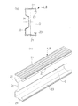
以下に本発明の好適な実施形態を図面に基づいて説明すると、図1の(a) は本発明に係る伸縮式足場板1の全体概略斜視図、(b) は(a) の矢印Xにて示す部分の拡大図であり、図2は図1の(b) のY−Y線拡大断面図である。この伸縮式足場板1は、足場板長さ方向に伸縮自在に組み合わされた一対の足場板本体2,3からなり、両足場板本体2,3は、図1の(b) 及び図2から分かるように、足場板幅方向に一定間隔をおいて互いに平行に配置された、夫々5本ずつの合計10本の足場板部材4,5,6,7,8からなるもので、一方の足場板本体2の足場板部材4,5,5,5,5が他方の足場板本体3の足場板部材6,7,7,7,8相互間に足場板長さ方向に相対移動自在に配置されている。   A preferred embodiment of the present invention will be described below with reference to the drawings. FIG. 1 (a) is an overall schematic perspective view of the telescopic scaffolding plate 1 according to the present invention, and (b) is an arrow X in (a). 2 is an enlarged cross-sectional view taken along line YY in FIG. 1B. The extendable scaffolding plate 1 is composed of a pair of scaffolding plate bodies 2 and 3 which are combined so as to be stretchable in the length direction of the scaffolding plate, and both the scaffolding plate bodies 2 and 3 are shown in FIG. 1 (b) and FIG. As can be seen, a total of ten scaffold plate members 4, 5, 6, 7 and 8 each of which is arranged in parallel with each other at a predetermined interval in the width direction of the scaffold plate, Scaffold plate members 4, 5, 5, 5, 5 of the plate body 2 are disposed so as to be relatively movable between the scaffold plate members 6, 7, 7, 7, 8 of the other scaffold plate body 3 in the length direction of the scaffold plate. Has been.

一方の足場板本体2の足場板部材4,5,5,5,5の足場板長さ方向一端部及び他方の足場板本体3の足場板部材6,7,7,7,8の足場板長さ方向一端部は、夫々、バンドプレート9,10によって相互に連結され、また一方の足場板本体2の足場板部材4,5,5,5,5の足場板長さ方向他端部及び他方の足場板本体3の足場板部材6,7,7,7,8の足場板長さ方向他端部は、夫々、全ての足場板部材4,5,6,7,8に亘るように外嵌されたバンドプレート11,12によって相互に連結されている。   One end of the scaffold plate members 4, 5, 5, 5, 5 in one scaffold plate body 2 in the longitudinal direction and the scaffold plate members 6, 7, 7, 7, 8 of the other scaffold plate body 3 One end in the length direction is connected to each other by the band plates 9 and 10, and the other end in the length direction of the scaffold plate of the scaffold plate members 4, 5, 5, 5, 5 of one scaffold plate body 2 and The other end of the scaffold plate members 6, 7, 7, 7, and 8 in the other scaffold plate body 3 in the length direction of the scaffold plate extends over all the scaffold plate members 4, 5, 6, 7, and 8, respectively. The band plates 11 and 12 are externally connected to each other.

図2は一方の足場板本体2の足場板部材4,5,5,5,5の他端部側が一方のバンドプレート11によって相互連結された部分の断面構造を示したもので、この一方のバンドプレート11は、一方の足場板本体2の足場板部材4,5,5,5,5の夫々他端部にビス13止め(あるいはリベット止め)され、他方のバンドプレート12は、図示は省略するが、他方の足場板本体3の足場板部材6,7,7,7,8の夫々他端部にビス13止め(あるいはリベット止め)され、従って両足場板本体2,3は足場板長さ方向に相対移動自在とされ、それによって足場板8は長さ方向に伸縮自在に構成されている。   FIG. 2 shows a cross-sectional structure of a portion where the other end portions of the scaffold plate members 4, 5, 5, 5, 5 of one scaffold plate body 2 are interconnected by one band plate 11. The band plate 11 is screwed (or riveted) to the other end of each of the scaffold plate members 4, 5, 5, 5 and 5 of one scaffold plate body 2, and the other band plate 12 is not shown. However, screws 13 (or rivets) are fixed to the other end portions of the scaffold plate members 6, 7, 7, 7, 8 of the other scaffold plate body 3, so that both of the scaffold plate bodies 2, 3 are the length of the scaffold plate The scaffolding plate 8 is configured to be freely movable in the longitudinal direction.

また、図1及び図2に示すように、両足場板本体2,3の足場板長さ方向両端部には、夫々棒状体からなる伸縮操作用ハンドル25,26が設けられている。即ち、図1の(b)
は足場板本体3の一端部に設けられたハンドル26を示しており、このハンドル26は、足場板本体3を構成する足場板部材6,7,7,7,8の足場板幅方向両端部の足場板部材6,8の先端部間にブラケット27,27を介して横架されている。このように足場板本体3の足場板幅方向両端部の足場板部材6,8の先端部間にハンドル26が横架されるため、その中間の足場板部材7,7,7の夫々先端部が切除され、しかしてこれら先端部が切除された足場板部材7,7,7とその両端側の足場板部材6,8とがバンドプレート10によって相互に連結されている。足場板本体2の一端部に設けられたハンドル25の取付構造も上記ハンドル26と同様である。
As shown in FIGS. 1 and 2, telescopic operation handles 25 and 26 each having a rod-like body are provided at both ends of the scaffold plate main bodies 2 and 3 in the length direction of the scaffold plate. That is, (b) of FIG.
Shows a handle 26 provided at one end of the scaffold plate body 3, and this handle 26 is the opposite ends of the scaffold plate members 6, 7, 7, 7, 8 constituting the scaffold plate body 3 in the scaffold plate width direction. The scaffold plate members 6 and 8 are horizontally mounted via brackets 27 and 27. As described above, since the handle 26 is horizontally mounted between the distal ends of the scaffold plate members 6 and 8 at both ends of the scaffold plate body 3 in the scaffold plate width direction, the distal ends of the intermediate scaffold plate members 7, 7, 7 are respectively provided. The scaffold plate members 7, 7, 7 with their tip portions removed and the scaffold plate members 6, 8 on both ends thereof are connected to each other by the band plate 10. The attachment structure of the handle 25 provided at one end of the scaffold board body 2 is the same as that of the handle 26.

上記のように両足場板本体2,3の足場板長さ方向両端部に伸縮操作用のハンドル25,26を設けたことにより、足場板本体2,3の伸縮操作を簡単容易に行なうことができる。またハンドル25,26は棒状体であるため、掴み易く、足場板本体2,3の伸縮操作が一層容易に行なえる。また、この棒状体からなるハンドル25,26は、図1の(b)
に示すように、足場板本体3を構成する足場板部材4,5,5,5,5(6,7,7,7,8)の足場板幅方向両端側の足場板部材4,5(6,8)間に横架されるから、足場板本体2,3の足場板長さ方向両端部に嵩張ることがなく的確に取り付けできる。
As described above, by providing the handles 25 and 26 for extending / contracting operation at both ends of the scaffolding plate main bodies 2 and 3 in the length direction of the scaffolding plate, the expansion and contraction operation of the scaffolding plate main bodies 2 and 3 can be performed easily and easily. it can. Moreover, since the handles 25 and 26 are rod-shaped bodies, they can be easily grasped and the scaffolding plate bodies 2 and 3 can be more easily expanded and contracted. Further, the handles 25 and 26 made of the rod-shaped body are formed as shown in FIG.
As shown in FIG. 2, the scaffold plate members 4, 5 (6, 7, 5, 5, 5 (6, 7, 7, 7, 8) constituting the scaffold plate body 3 on both sides in the width direction of the scaffold plate. 6 and 8), the scaffolding plate main bodies 2 and 3 can be accurately attached without being bulky at both ends of the scaffolding plate length direction.

上記一方の足場板本体2における足場板幅方向一端側の足場板部材4と、この足場板部材6に対向する、他方の足場板本体3の足場板幅方向一端側の足場板部材6との間には、両方の足場板本体2,3を所要の伸縮位置にロックするためのロック装置Rが介装されている。尚、この伸縮式足場板1は、その上面側と下面側とは同じ形状であって、上下何れの側を上向きにして使用することができる。   A scaffold plate member 4 on one end side in the scaffold plate width direction of the one scaffold plate body 2 and a scaffold plate member 6 on one end side in the scaffold plate width direction of the other scaffold plate body 3 facing the scaffold plate member 6. In between, a lock device R for locking both scaffold board main bodies 2 and 3 in a required expansion / contraction position is interposed. The telescopic scaffolding plate 1 has the same shape on the upper surface side and the lower surface side, and can be used with either the upper or lower side facing upward.

上記一対の足場板本体2,3を構成する全ての足場板部材4,5,6,7,8は、夫々アルミ押出型材からなり、これら全ての足場板部材4,5,6,7,8のうち足場板幅方向に関して最も外側にある二つの足場板部材4,8は、図2に示すように、夫々リップ付き溝型材からなるもので、その溝型材の開口部O側を外に向けて配置することによって、このリップ付き溝型材からなる足場板部材4,8のリップ部23を手掛り部として利用するようにしたものである(図5参照)。   All the scaffold plate members 4, 5, 6, 7, and 8 constituting the pair of scaffold plate bodies 2 and 3 are each made of an aluminum extrusion mold material, and all these scaffold plate members 4, 5, 6, 7, and 8 are formed. 2, the two outermost scaffold plate members 4, 8 in the width direction of the scaffold plate are each made of a grooved material with a lip, as shown in FIG. 2, with the opening O side of the grooved material facing outward. Thus, the lip portion 23 of the scaffold plate members 4 and 8 made of the grooved material with lips is used as a cue portion (see FIG. 5).

即ち、全足場板部材4,5,6,7,8のうち最も外側にある二つの足場板部材4,8は、共に同じ断面形状のリップ付き溝型材からなるもので、図3の(a) 及び(b) に示す。この足場板部材4,8は、対向する側壁部21,21と両側壁部21,21をつなぐ底壁部22と、各側壁部21の先端部から内向きに略L字状に突設されたリップ部23とによって溝形に形成されると共に、底壁部22にはその幅方向中央部側に補強用凸条部24が形成されている。   That is, the two outermost scaffold plate members 4 and 8 out of all the scaffold plate members 4, 5, 6, 7 and 8 are both made of a grooved material with a lip having the same cross-sectional shape. ) And (b). The scaffolding plate members 4 and 8 are projected in a substantially L shape inward from the bottom wall portion 22 that connects the opposite side wall portions 21 and 21 and both side wall portions 21 and 21 and the distal end portion of each side wall portion 21. The lip portion 23 forms a groove shape, and the bottom wall portion 22 has a reinforcing ridge portion 24 formed at the center in the width direction.

また、図2から分かるように、一方の足場板本体2の一部を構成する足場板部材5と、他方の足場板本体3の一部を構成する足場板部材7とは同じ断面形状のアルミ押出型材、即ち断面が縦長矩形状の角筒状型材によって形成されたもので、この足場板部材5,7の拡大断面形状を図5に示す。   As can be seen from FIG. 2, the scaffold plate member 5 constituting a part of one scaffold plate body 2 and the scaffold plate member 7 constituting a part of the other scaffold plate body 3 have the same sectional shape. FIG. 5 shows an enlarged cross-sectional shape of the scaffold plate members 5, 7, which is formed by an extruded mold material, that is, a rectangular tube-shaped mold material whose section is a vertically long rectangular shape.

図4の(a) は、一方の足場板本体2における足場板幅方向一端側の足場板部材4と対面する他方の足場板本体3の足場板幅方向一端側の足場板部材6を示す斜視図、(b) はその断面図である。この足場板部材6は、両側一対の筒状部6a,6aと両筒状部6a,6aをつなぐ連結壁部6bとからなる。   FIG. 4A is a perspective view showing a scaffold plate member 6 on one end side in the scaffold plate width direction of the other scaffold plate body 3 facing the scaffold plate member 4 on one end side in the scaffold plate width direction in one scaffold plate body 2. FIG. 2B is a cross-sectional view thereof. The scaffold plate member 6 includes a pair of cylindrical portions 6a and 6a on both sides and a connecting wall portion 6b that connects the cylindrical portions 6a and 6a.

上記のように構成される伸縮式足場板1を作業現場等において所要の使用場所へ移動させる時は、図5に示すように、足場板1の上下面が水平面に対し垂直となる状態で、この足場板1の長さ方向中央部側において最も上側に位置するリップ付き溝型材からなる足場板部材8(又は4)のリップ部23を掴むことにより、このリップ部23が有効な手掛り部となって、足場板1を所定の場所まで簡単容易に持ち運ぶことができる。この場合に、足場板1は、図1の(a) に示すような伸張状態のままでもよいし、完全に収縮した状態でもよい。   When the telescopic scaffolding plate 1 configured as described above is moved to a required place of use at a work site or the like, as shown in FIG. 5, with the upper and lower surfaces of the scaffolding plate 1 being perpendicular to the horizontal plane, By grasping the lip portion 23 of the scaffold plate member 8 (or 4) made of a grooved material with a lip located on the uppermost side in the longitudinal direction center portion side of the scaffold plate 1, the lip portion 23 becomes an effective clue portion. Thus, the scaffold board 1 can be easily carried to a predetermined place. In this case, the scaffold plate 1 may be in an expanded state as shown in FIG. 1 (a) or in a completely contracted state.

尚、図5では、最も上側に位置する足場板部材8のリップ部23の裏側に人差指1本を当てがってその人差指と親指で足場板部材8を把持しているように見えるが、実際には、この足場板部材8のリップ部23の裏側に人差指、中指、薬指及び小指の4本の指を差し込むと共に、親指を側壁部21の外側面に当て付けた状態で、足場板部材8を掴むようになる。   In FIG. 5, it seems that one index finger is applied to the back side of the lip portion 23 of the uppermost scaffold plate member 8 and the scaffold plate member 8 is gripped by the index finger and thumb. In the state where the four fingers of the index finger, the middle finger, the ring finger and the little finger are inserted into the back side of the lip portion 23 of the scaffold plate member 8 and the thumb is applied to the outer surface of the side wall portion 21, the scaffold plate member 8 To grab.

(a) は本発明に係る伸縮式足場板の全体概略斜視図、(b) は(a) の矢印Xにて示す部分の拡大図である。(a) is the whole schematic perspective view of the expansion-contraction type scaffolding plate concerning this invention, (b) is an enlarged view of the part shown by the arrow X of (a). 図1の(b) のY−Y線拡大断面図である。It is the YY line expanded sectional view of (b) of FIG. 両足場板本体を構成する全足場板部材のうち最も外側にある足場板部材を示す斜視図、(b) はその断面図である。The perspective view which shows the outermost scaffold board member among all the scaffold board members which comprise both scaffold board main bodies, (b) is the sectional drawing. (a) は、一方の足場板本体における足場板幅方向一端側の足場板部材と対面する他方の足場板本体の足場板幅方向一端側の足場板部材を示す斜視図、(b) はその断面図である。(a) is a perspective view showing a scaffold plate member at one end side in the scaffold plate width direction of the other scaffold plate body facing the scaffold plate member at one end side in the scaffold plate width direction at one scaffold plate body, and (b) is its perspective view. It is sectional drawing. この伸縮式足場板を持ち運びする時の足場板部材の掴み状態を示す断面図である。It is sectional drawing which shows the holding | grip state of the scaffold board member at the time of carrying this expansion-contraction type scaffold board.

符号の説明Explanation of symbols

1 伸縮式足場板
2,3 足場板本体
4 足場板部材(最も外側の足場板部材)
5 足場板部材
6 足場板部材
7 足場板部材
8 足場板部材(最も外側の足場板部材)
23 リップ付き溝型材からなる足場板部材のリップ部
25,26 伸縮操作用ハンドル
1 Telescoping scaffolding plates 2, 3 Scaffolding plate body 4 Scaffolding plate member (outermost scaffolding plate member)
5 Scaffold board member 6 Scaffold board member 7 Scaffold board member 8 Scaffold board member (outermost scaffold board member)
23. Lip parts 25 and 26 of the scaffold plate member made of a grooved material with a lip.

Claims (4)

伸縮自在に組み合わされた一対の足場板本体からなり、各足場板本体は足場板幅方向に一定間隔をおいて互いに平行に配置された複数の足場板部材を有し、一方の足場板本体の足場板部材が他方の足場板本体の足場板部材間に足場板長さ方向に相対移動自在に配置されてなる伸縮式足場板において、両足場板本体の全ての足場板部材のうち最も外側にある二つの足場板部材は、夫々リップ付き溝型材からなるもので、その溝型材の開口部側を外に向けて配置されることを特徴とする伸縮式足場板。   It consists of a pair of scaffolding plate bodies combined in a stretchable manner, and each scaffolding plate body has a plurality of scaffolding plate members arranged parallel to each other at a certain interval in the scaffolding plate width direction. In a telescopic scaffolding plate in which the scaffolding plate member is disposed between the scaffolding plate members of the other scaffolding plate body so as to be relatively movable in the length direction of the scaffolding plate, the outermost of all the scaffolding plate members of both scaffolding plate bodies The two scaffolding plate members are each made of a grooved material with a lip, and are arranged with the opening side of the grooved material facing outward. 前記リップ付き溝型材からなる足場板部材にはその溝型材の底壁部に、内向きに突出する補強用凸条部が足場板部材長さ方向全長に亘って形成されていることを特徴とする請求項1に記載の伸縮式足場板。   The scaffold plate member made of a grooved material with a lip is characterized in that a reinforcing ridge that protrudes inward is formed on the bottom wall portion of the grooved material over the entire length of the scaffold plate member. The telescopic scaffold board according to claim 1. 両足場板本体の足場板長さ方向両端部には、夫々伸縮操作用のハンドルが設けられている請求項1又は2に記載の伸縮式足場板。   The telescopic scaffold board according to claim 1 or 2, wherein handles for telescopic operation are provided at both ends of the scaffold board main body in the length direction of the scaffold board. 各ハンドルは、足場板本体を構成する足場板部材の足場板幅方向両端側の足場板部材の先端部間に横架された棒状体からなり、この両端側の足場板部材間の中間の足場板部材の夫々先端部が切除され、この先端部が切除された足場板部材とその両端側の足場板部材とがバンドプレートによって相互に連結されている請求項3に記載の伸縮式足場板。
Each handle is composed of a rod-like body that is laid between the distal ends of the scaffold plate members on both sides in the width direction of the scaffold plate of the scaffold plate member constituting the scaffold plate body, and an intermediate scaffold between the scaffold plate members on both ends. The telescoping scaffolding plate according to claim 3, wherein the front end portions of the plate members are cut off, and the scaffold plate members from which the front end portions are cut off and the scaffold plate members on both ends thereof are connected to each other by band plates.
JP2006073271A 2006-03-16 2006-03-16 Extendable scaffold board Pending JP2007247292A (en)

Priority Applications (1)

Application Number Priority Date Filing Date Title
JP2006073271A JP2007247292A (en) 2006-03-16 2006-03-16 Extendable scaffold board

Applications Claiming Priority (1)

Application Number Priority Date Filing Date Title
JP2006073271A JP2007247292A (en) 2006-03-16 2006-03-16 Extendable scaffold board

Publications (1)

Publication Number Publication Date
JP2007247292A true JP2007247292A (en) 2007-09-27

Family

ID=38591878

Family Applications (1)

Application Number Title Priority Date Filing Date
JP2006073271A Pending JP2007247292A (en) 2006-03-16 2006-03-16 Extendable scaffold board

Country Status (1)

Country Link
JP (1) JP2007247292A (en)

Citations (3)

* Cited by examiner, † Cited by third party
Publication number Priority date Publication date Assignee Title
JPS58130547U (en) * 1982-02-27 1983-09-03 日本軽金属株式会社 scaffolding board
JPS6029831U (en) * 1983-08-03 1985-02-28 ムツミ工業株式会社 channel steel
JPS6031447U (en) * 1983-08-08 1985-03-04 株式会社 カンサカ telescopic scaffolding board

Patent Citations (3)

* Cited by examiner, † Cited by third party
Publication number Priority date Publication date Assignee Title
JPS58130547U (en) * 1982-02-27 1983-09-03 日本軽金属株式会社 scaffolding board
JPS6029831U (en) * 1983-08-03 1985-02-28 ムツミ工業株式会社 channel steel
JPS6031447U (en) * 1983-08-08 1985-03-04 株式会社 カンサカ telescopic scaffolding board

Similar Documents

Publication Publication Date Title
US4524484A (en) Extension handle having cooperating male and female locking sleeves
US7370384B2 (en) Combination wedge and notch trowel with reversible grip handle
US3981043A (en) Slidable tool grip
US20190315318A1 (en) Scraper Device
SE523253C2 (en) Foldable ladder
US6526619B1 (en) Gutter cleaning system
US9676112B2 (en) Extender and method for holding a razor
US7971310B2 (en) Cleaning tool
US20060101655A1 (en) Apparatus for removing body hair
US6915580B2 (en) Extendable razor handle assembly
JP2010511469A5 (en)
US8510910B1 (en) Air blower device for cleaning a rain gutter and other elevated surfaces
DE50115631D1 (en) Hand tool with at least one handle
JP2007532166A5 (en)
US6256829B1 (en) Telescoping broom
WO2015073829A1 (en) Extendable tool attachment stick
JP2007247292A (en) Extendable scaffold board
US7470084B2 (en) Ergonomic concrete hand screed
US2705433A (en) Multi-jawed wrench having slidable handgrip
US4497405A (en) Wrench holder
US6425162B1 (en) Retractable handle device having adjustable structure
US9307867B2 (en) Fruit splitting device
CA2580364A1 (en) Handle for a cleaning device
WO2019225478A1 (en) Simple protective tube inserter
JP3187349U (en) Snow remover

Legal Events

Date Code Title Description
A621 Written request for application examination

Free format text: JAPANESE INTERMEDIATE CODE: A621

Effective date: 20071101

A977 Report on retrieval

Free format text: JAPANESE INTERMEDIATE CODE: A971007

Effective date: 20100416

A131 Notification of reasons for refusal

Free format text: JAPANESE INTERMEDIATE CODE: A131

Effective date: 20100421

A02 Decision of refusal

Free format text: JAPANESE INTERMEDIATE CODE: A02

Effective date: 20100818