JP2007242566A - Wall surface switch remote control device - Google Patents
Wall surface switch remote control device Download PDFInfo
- Publication number
- JP2007242566A JP2007242566A JP2006066788A JP2006066788A JP2007242566A JP 2007242566 A JP2007242566 A JP 2007242566A JP 2006066788 A JP2006066788 A JP 2006066788A JP 2006066788 A JP2006066788 A JP 2006066788A JP 2007242566 A JP2007242566 A JP 2007242566A
- Authority
- JP
- Japan
- Prior art keywords
- switch
- remote control
- wall surface
- control device
- signal
- Prior art date
- Legal status (The legal status is an assumption and is not a legal conclusion. Google has not performed a legal analysis and makes no representation as to the accuracy of the status listed.)
- Pending
Links
Images


Landscapes
- Circuit Arrangement For Electric Light Sources In General (AREA)
- Mechanisms For Operating Contacts (AREA)
Abstract
Description
本発明は、一般家庭用の壁面スイッチの遠隔操作を図った装置に関する。 The present invention relates to an apparatus for remotely controlling a wall switch for general household use.
一般家庭では、天井などに設けられている照明等のオン、オフを壁面に設置されているシーソー型あるいは押しボタン型スイッチで行うことが多い。このようなタイプのスイッチを用いる場合には、スイッチのオン、オフを行うときに壁面のスイッチのところまで行かなければならないために、たとえば身体が不自由な場合には不便であったり、就寝時などにも面倒であったりすることがある。このためリモコンで照明器具を操作できるようにすることが考えられ、照明器具本体にリモコン機能を組み込んだものが存在する。このように照明器具自体にリモコン機能を持たせるためには、照明器具自体をリモコン機能を内蔵するものに取り替えることが必要で、多額の経費が必要となる。
そこで照明器具自体を替えるのではなく、既存の照明器具にリモコンで操作されるスイッチ回路を有する装置を付加するものが存在する。たとえば天井につり下げるタイプの照明器具では、天井の電源に照明器具を接続し、照明器具に取付けられたひも状のスイッチを引き下げてスイッチを切り替えたり、壁面スイッチで天井の電源をオン、オフさせて点灯、消灯させる場合が多い。この天井つり下げ型の照明装置に、リモコン機能を付加するものとして天井の電源と照明器具本体の間にリモコン操作で電源回路をオン、オフできる機能を有する装置を付加してリモコン操作をするものがある(例えば、特許文献1参照。)。
In general homes, lighting on a ceiling or the like is often turned on and off by a seesaw type or push button type switch installed on a wall surface. When using this type of switch, it is necessary to go to the wall switch when turning the switch on and off. For example, it is inconvenient if the body is inconvenient or at bedtime. May be troublesome. For this reason, it is conceivable that the luminaire can be operated with a remote controller, and there is a luminaire body incorporating a remote control function. Thus, in order to give the lighting fixture itself a remote control function, it is necessary to replace the lighting fixture itself with a built-in remote control function, which requires a large amount of expenses.
Therefore, there is a device in which a device having a switch circuit operated by a remote controller is added to an existing lighting device instead of changing the lighting device itself. For example, in the case of a lighting fixture that hangs on the ceiling, connect the lighting fixture to the ceiling power supply, pull down the string-like switch attached to the lighting fixture to switch the switch, or turn the ceiling power on and off with the wall switch. Often turn on and off. To add a remote control function to this ceiling-suspended lighting device, add a device that has a function to turn the power circuit on and off by remote control between the ceiling power supply and the luminaire body, and operate the remote control (For example, refer to Patent Document 1).
また、前記の壁面等に設置されているシーソー型あるいは押しボタン型スイッチにリモコン機能を与えるために、スイッチ内部の回路に直接、リモコン操作でオン・オフする回路を付加して、リモコンにより回路をオン、オフするものがある(例えば、特許文献2参照。)。 In addition, in order to give a remote control function to the seesaw type or push button type switch installed on the wall surface etc., a circuit that is turned on / off by remote control operation is added directly to the circuit inside the switch, and the circuit is controlled by the remote control. Some are turned on and off (see, for example, Patent Document 2).
以上に述べたように、特許文献1では天井に後付で照明器具を取付ける場合にリモコン機能を持った装置を付加できるが、照明器具自体が天井面に固定されたものには対応できない。また、特許文献2の装置の設置には,回路の電気工事が必要となり、電気工事の資格を有しなければ工事を行うことができないために、簡単に取付けることはできない。
As described above, in
このように現状では、壁面に設置された操作ノブの切り替えによりオンまたはオフのスイッチングをするスイッチを簡単にリモコン操作でオン、オフできる装置はない。 Thus, at present, there is no device that can easily turn on / off a switch that is turned on or off by switching an operation knob installed on a wall surface by remote control operation.
壁面等に配置され、操作ノブの切り替えによりオンまたはオフのスイッチングをするスイッチを操作する装置であって、リモコン送信部とリモコン受信部、受信部の信号を受けて回路を制御する制御部、制御部からの信号で駆動する駆動部、駆動部の駆動により、前記スイッチの操作ノブに接触し機械的に直接切り替え操作をする操作部を有した装置からなり、壁面等に前記スイッチの上から取付ける構造をしたものである。 A device that is arranged on a wall surface or the like and that operates a switch that switches on or off by switching an operation knob. The remote control transmission unit and the remote control reception unit, the control unit that receives the signals from the reception unit and controls the circuit, the control A drive unit that is driven by a signal from the unit, and a device having an operation unit that mechanically switches directly by touching the operation knob of the switch by driving the drive unit, and is mounted on a wall surface or the like from above the switch It has a structure.
上記の課題解決手段による作用は次の通りである。すなわち、操作ノブの切り替えによりオンまたはオフのスイッチングをするスイッチの上から取付けてリモコン操作を行うことができる装置であるために、一般家庭の壁面スイッチで操作する器具に、ほとんど適応でき、固定型の照明器具の場合でも、照明器具そのものを取り替える工事も必要としない。また配線工事も伴わないために、誰でも手軽に本発明を取付けることで、器具をリモコンで操作をできるようになる。 The operation of the above problem solving means is as follows. In other words, since it is a device that can be mounted from above the switch that switches on or off by switching the operation knob and can be operated by remote control, it is almost applicable to appliances that are operated with wall switches in general households, fixed type Even in the case of other lighting fixtures, there is no need to replace the lighting fixtures themselves. Moreover, since no wiring work is involved, anyone can easily operate the instrument with the remote control by attaching the present invention.
以下、本発明の一実施例を図1〜図3に基づいて説明する。 An embodiment of the present invention will be described below with reference to FIGS.
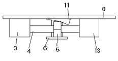
図1は本発明が、壁面に設置されているシーソー型スイッチ11に、後付けで取付け可能であることを示すもので、本発明の基板8を取付け穴7を用いて壁面スイッチの取付けねじ穴10にねじ止めする。その際に壁面シーソー型スイッチ11がスイッチ穴12に入るように取付ける。基板8には電池などよりなる電源2があり、リモコン受信部1、モーターおよびギアボックス3、制御部9の電源をここから供給する。リモコン受信部1はリモコン送信機から送られたスイッチオンの信号を受信すると制御部9に信号を送る。制御部9は前記信号を受けると、モーターおよびギアボックス3のモーターを正回転させる。その回転に伴いモーターに連結された駆動用ねじ4は回転する。
FIG. 1 shows that the present invention can be attached to a
駆動用ねじ4の片方の端部はモーターおよびギアボックス3に連結されており、もう一方の端部はねじ保持部13で保持されている。ナット5は,ねじ4の中間あたりに位置し,基板8に固定されたナット回転止め6はナット5が回転しないようにナット5の平面部分と接触した構造である。このため、ねじ4が回転したときにナット5は回転できないために、ねじの軸方向に移動する。このナット5の移動により、壁面スイッチ11の切り替え操作を行いスイッチをオンする。
One end of the
壁面スイッチ11の切り替えをねじの回転数で確認し、切り替えが終わったと判断すると、制御部9はモーターおよびギアボックス3の回転を止める。そして次にリモコン送信機よりスイッチオフの信号がリモコン受信部1に送られると、その信号が制御部9に伝えられ、制御部9はモーターおよびギアボックス3を通してねじ4を逆回転させて、ナット5を戻す方向に動かし壁面スイッチ11をオフ方向に切り替える。このようにしてリモコンで壁面スイッチ11の切り替えを行う。
When the switching of the
壁面スイッチが図3で示すような押ボタンスイッチ14である場合には、ナット回転止め6に揺動できるように取付けられたシーソー部材支点部16を有するシーソー部材15を追加したもので対応可能である。スイッチオンの信号がリモコン送信機から送られると前記実施例1と同様の機構よりナット5が移動しシーソー部材15を押し、シーソー部材支点部16を支点としてシーソー部材15が傾き、押ボタンスイッチ14をオンさせる。次にスイッチオフの信号が送られるとナット5は前記と逆方向に移動しシーソー部材15を押し、前記と逆に傾かせ、押ボタンスイッチ14をオフさせる。
When the wall switch is a
上記のようなねじのリニアガイド機構で壁面スイッチを切り替える機構ではなく、ソレノイド可動部分の押引動作により、壁面スイッチを切り替える構造でもよい。この場合、図の符号3、4、5、6に替わりソレノイドを取付ける。
Instead of the mechanism for switching the wall surface switch with the screw linear guide mechanism as described above, a structure for switching the wall surface switch by pushing and pulling the solenoid movable part may be used. In this case, a solenoid is attached instead of the
容易に既存の壁面スイッチに取付けできるため、天上面に固定された照明器具であっても、壁面スイッチを有した照明器具なら対応することができる。その他壁面に付けられたスイッチで動作の切り替えを行うものであれば照明器具以外のもにも対応できる。 Since it can be easily attached to an existing wall switch, a lighting fixture having a wall switch can be used even if the lighting fixture is fixed to the top surface. Other than the lighting fixtures, other switches can be used as long as the operation is switched by a switch attached to the wall surface.
1 リモコン受信部
2 電源
3 モーターおよびギアボックス
4 駆動用ねじ
5 ナット
6 ナット回転止め
7 取付け穴
8 基板
9 制御部
10 壁面スイッチの取付けねじ穴
11 壁面シーソー型スイッチ
12 スイッチ穴
13 ねじ保持部
14 押ボタンスイッチ
15 シーソー部材
16 シーソー部材支点部
DESCRIPTION OF
Claims (1)
A device that is arranged on a wall surface or the like and operates a switch that switches on or off by switching an operation knob, and controls a circuit by receiving a signal from a remote control receiving unit and receiving a signal from a remote control transmitting unit A control unit, a drive unit driven by a signal from the control unit, and a device having an operation unit that mechanically switches directly by touching the operation knob of the switch by driving the drive unit. A wall surface switch remote control device comprising holding means for mounting from above.
Priority Applications (1)
| Application Number | Priority Date | Filing Date | Title |
|---|---|---|---|
| JP2006066788A JP2007242566A (en) | 2006-03-10 | 2006-03-10 | Wall surface switch remote control device |
Applications Claiming Priority (1)
| Application Number | Priority Date | Filing Date | Title |
|---|---|---|---|
| JP2006066788A JP2007242566A (en) | 2006-03-10 | 2006-03-10 | Wall surface switch remote control device |
Publications (1)
| Publication Number | Publication Date |
|---|---|
| JP2007242566A true JP2007242566A (en) | 2007-09-20 |
Family
ID=38587884
Family Applications (1)
| Application Number | Title | Priority Date | Filing Date |
|---|---|---|---|
| JP2006066788A Pending JP2007242566A (en) | 2006-03-10 | 2006-03-10 | Wall surface switch remote control device |
Country Status (1)
| Country | Link |
|---|---|
| JP (1) | JP2007242566A (en) |
Cited By (10)
| Publication number | Priority date | Publication date | Assignee | Title |
|---|---|---|---|---|
| WO2014066272A1 (en) * | 2012-10-26 | 2014-05-01 | Lutron Electronics Co., Inc. | Battery-powered retrofit remote control device |
| KR101423082B1 (en) * | 2013-01-11 | 2014-07-24 | 한밭대학교 산학협력단 | Voice recognition switch system |
| CN104851682A (en) * | 2015-04-27 | 2015-08-19 | 苏州君丰辰电子科技有限公司 | Dual-supply change-over switch |
| CN104851683A (en) * | 2015-04-27 | 2015-08-19 | 苏州君丰辰电子科技有限公司 | Intelligent household power switch easy to assemble |
| CN104851684A (en) * | 2015-04-27 | 2015-08-19 | 苏州君丰辰电子科技有限公司 | Remote operation mechanism used for intelligent household power switch |
| CN104867742A (en) * | 2015-04-27 | 2015-08-26 | 苏州君丰辰电子科技有限公司 | Distribution switch easy to assemble |
| US9538619B2 (en) | 2012-10-26 | 2017-01-03 | Lutron Electronics Co., Inc. | Controllable light source |
| US9633557B2 (en) | 2014-06-24 | 2017-04-25 | Lutron Electronics Co., Inc. | Battery-powered retrofit remote control device |
| CN108776442A (en) * | 2018-04-28 | 2018-11-09 | 武汉领普科技有限公司 | A kind of self power generation passive switch and its working method |
| US11330690B2 (en) | 2016-08-31 | 2022-05-10 | Chin-Wei Chao | Switching device with auxiliary power unit and wireless receiver function, and lamp system using the same |
-
2006
- 2006-03-10 JP JP2006066788A patent/JP2007242566A/en active Pending
Cited By (20)
| Publication number | Priority date | Publication date | Assignee | Title |
|---|---|---|---|---|
| US10104750B2 (en) | 2012-10-26 | 2018-10-16 | Lutron Electronics Co., Inc. | Controllable light source |
| US9538619B2 (en) | 2012-10-26 | 2017-01-03 | Lutron Electronics Co., Inc. | Controllable light source |
| US11837418B2 (en) | 2012-10-26 | 2023-12-05 | Lutron Technology Company Llc | Battery-powered retrofit remote control device |
| US10849206B2 (en) | 2012-10-26 | 2020-11-24 | Lutron Technology Company Llc | Battery-powered retrofit remote control device |
| US11102874B2 (en) | 2012-10-26 | 2021-08-24 | Lutron Technology Company Llc | Controllable light source |
| WO2014066272A1 (en) * | 2012-10-26 | 2014-05-01 | Lutron Electronics Co., Inc. | Battery-powered retrofit remote control device |
| US10418193B2 (en) | 2012-10-26 | 2019-09-17 | Lutron Tehnology Company LLC | Controllable light source |
| US9565742B2 (en) | 2012-10-26 | 2017-02-07 | Lutron Electronics Co., Inc. | Battery-powered retrofit remote control device |
| US11102875B2 (en) | 2012-10-26 | 2021-08-24 | Lutron Technology Company Llc | Battery-powered retrofit remote control device |
| US10147560B2 (en) | 2012-10-26 | 2018-12-04 | Lutron Electronics Co., Inc. | Battery-powered retrofit remote control device |
| KR101423082B1 (en) * | 2013-01-11 | 2014-07-24 | 한밭대학교 산학협력단 | Voice recognition switch system |
| US9633557B2 (en) | 2014-06-24 | 2017-04-25 | Lutron Electronics Co., Inc. | Battery-powered retrofit remote control device |
| US11043115B2 (en) | 2014-06-24 | 2021-06-22 | Lutron Technology Company Llc | Battery-powered retrofit remote control device |
| US11657702B2 (en) | 2014-06-24 | 2023-05-23 | Lutron Technology Company Llc | Battery-powered retrofit remote control device |
| CN104867742A (en) * | 2015-04-27 | 2015-08-26 | 苏州君丰辰电子科技有限公司 | Distribution switch easy to assemble |
| CN104851684A (en) * | 2015-04-27 | 2015-08-19 | 苏州君丰辰电子科技有限公司 | Remote operation mechanism used for intelligent household power switch |
| CN104851683A (en) * | 2015-04-27 | 2015-08-19 | 苏州君丰辰电子科技有限公司 | Intelligent household power switch easy to assemble |
| CN104851682A (en) * | 2015-04-27 | 2015-08-19 | 苏州君丰辰电子科技有限公司 | Dual-supply change-over switch |
| US11330690B2 (en) | 2016-08-31 | 2022-05-10 | Chin-Wei Chao | Switching device with auxiliary power unit and wireless receiver function, and lamp system using the same |
| CN108776442A (en) * | 2018-04-28 | 2018-11-09 | 武汉领普科技有限公司 | A kind of self power generation passive switch and its working method |
Similar Documents
| Publication | Publication Date | Title |
|---|---|---|
| JP2007242566A (en) | Wall surface switch remote control device | |
| KR20110062879A (en) | Parking release apparatus for shift by wire type shifting device | |
| EP1764815B8 (en) | Switching apparatus | |
| JP2010502170A5 (en) | ||
| CA2583854A1 (en) | Apparatus for remotely actuating a manual actuator of a circuit breaker | |
| GB2490932A (en) | Rocker switch actuator | |
| TW200720148A (en) | Bicycle operating component with electrical shift control switch | |
| JP2009043664A (en) | Switch adapter, and illumination control system using the same | |
| CN103367060A (en) | Miniature circuit breaker | |
| WO2016115756A1 (en) | Electric torch capable of dimming conveniently and rapidly | |
| US20140262713A1 (en) | Wall switch assembly | |
| KR101125600B1 (en) | Apparatus for driving valves | |
| KR100361371B1 (en) | apparatus for operating a switch | |
| JP2010011065A (en) | Control device and method of apparatus having push switch | |
| JP2001311196A (en) | Drive device for drain plug | |
| KR101949487B1 (en) | Valve assembly | |
| WO2006071968A3 (en) | Multifunction switching arrangement for controlling transmission overdrive and autostick functions | |
| JP2006073220A (en) | Switch remote controller | |
| KR20160035932A (en) | Apparatus for controlling switch of lamp | |
| JP4892747B2 (en) | Equipment control device | |
| CN105513911A (en) | Miniature circuit breaker remote-control operating mechanism with electrically operated mechanism | |
| JP4892750B2 (en) | Control device for equipment having toggle switch | |
| JP5581185B2 (en) | Load control switch and load control switch system | |
| JP2006332939A (en) | Remote control apparatus for air-conditioner | |
| CN203406246U (en) | Miniature breaker remote control operating mechanism |