JP2007241320A - Fixing device and image forming apparatus - Google Patents
Fixing device and image forming apparatus Download PDFInfo
- Publication number
- JP2007241320A JP2007241320A JP2007166545A JP2007166545A JP2007241320A JP 2007241320 A JP2007241320 A JP 2007241320A JP 2007166545 A JP2007166545 A JP 2007166545A JP 2007166545 A JP2007166545 A JP 2007166545A JP 2007241320 A JP2007241320 A JP 2007241320A
- Authority
- JP
- Japan
- Prior art keywords
- fixing device
- heat conductive
- sheet
- heat
- contact
- Prior art date
- Legal status (The legal status is an assumption and is not a legal conclusion. Google has not performed a legal analysis and makes no representation as to the accuracy of the status listed.)
- Pending
Links
Images


Abstract
Description
本発明は、定着装置および画像形成装置に関し、さらに詳しくは、ベルトを用いて記録用紙などのシート上の未定着画像を定着するための構成に関する。 The present invention relates to a fixing device and an image forming apparatus, and more particularly to a configuration for fixing an unfixed image on a sheet such as recording paper using a belt.
複写機やファクシミリあるいはプリンタさらには印刷機などの画像形成装置においては、記録用紙などのシート上に転写されて担持されている未定着画像を加熱定着することで複写物や記録物を得ることができる。
定着装置には、一対のローラによりシートを挟持搬送しながら一方のローラからシート上の未定着画像を加熱する構成がある。
In an image forming apparatus such as a copying machine, a facsimile, a printer, or a printing machine, a copy or a recorded material can be obtained by heating and fixing an unfixed image transferred and carried on a sheet such as recording paper. it can.
The fixing device has a configuration in which an unfixed image on a sheet is heated from one roller while the sheet is nipped and conveyed by a pair of rollers.
ローラ同士により定着を行う構成とは別に、ローラよりも熱容量が小さいベルトを加熱媒体とし、これとローラとを組み合わせた構成がある。
上記構成では、一対のローラに掛け回されたベルトと、ローラの一つに対峙して当接することによりシートのニップ部を構成する加圧ローラとを備え、ベルトにおける加圧ローラに対向する側の展張面をシートの移動方向に移動させるようになっている。この構成では、ベルトが掛け回されているローラのうちで、上記展張面の移動方向上流側に位置するローラによりベルトを加熱し、その移動方向に応じてシートを案内することによりニップ部にてシート上の未定着画像を定着することができる。
In addition to the configuration in which the fixing is performed between the rollers, there is a configuration in which a belt having a smaller heat capacity than the rollers is used as a heating medium, and this is combined with the rollers.
In the above configuration, the belt includes a belt wound around the pair of rollers, and a pressure roller that forms a nip portion of the sheet by contacting and facing one of the rollers, and the side of the belt facing the pressure roller The extending surface is moved in the moving direction of the sheet. In this configuration, among the rollers around which the belt is wound, the belt is heated by a roller located on the upstream side in the movement direction of the expansion surface, and the sheet is guided according to the movement direction at the nip portion. An unfixed image on the sheet can be fixed.
ベルトは、ローラに比べて体積が小さくされることで熱容量を小さくできるので、短時間での温度上昇が可能であり、上述したローラ対のみを用いた場合に比べて始動時での温度立ち上がりが早いという利点がある。 Since the heat capacity can be reduced by reducing the volume of the belt compared to the rollers, the temperature can be increased in a short time, and the temperature rise at the start-up is higher than when only the above-described roller pair is used. There is an advantage of being fast.
画像形成装置には、フルカラーを含む多色画像を形成できる構成を備えたものがある。この種、多色画像形成装置(以下、フルカラー画像を対象としてカラー画像形成装置という)においては、得られる画像の光沢度を異ならせる場合がある。例えば、写真画像と文字画像とでは、写真画像の方を入射光に対する反射光量を意味する光沢度を異ならせることが多い。これは、文字画像に比べて写真画像の方が見栄えの良い彩度を望まれることが多いことが理由とされる。 Some image forming apparatuses have a configuration capable of forming a multicolor image including a full color. In this type of multicolor image forming apparatus (hereinafter referred to as a color image forming apparatus for a full color image), the glossiness of the obtained image may be different. For example, a photographic image and a character image often have different glossiness, which means the amount of reflected light with respect to incident light. The reason for this is that photographic images often desire better-looking saturation than character images.
光沢度に影響する要因としては、未定着画像に含まれるトナーの熱的性質が挙げられ、熱的性質のうちでもガラス転移点に影響される。このため、従来では、定着装置におけるトナーへの加熱条件となる、温度、シートの線速およびニップ圧力を異ならせるようにした構成が提案されている(例えば、特許文献1〜5)。 Factors affecting the glossiness include the thermal properties of the toner contained in the unfixed image, and among the thermal properties, it is influenced by the glass transition point. For this reason, conventionally, configurations have been proposed in which the temperature, the linear velocity of the sheet, and the nip pressure, which are the heating conditions for the toner in the fixing device, are made different (for example, Patent Documents 1 to 5).
各特許文献には、ベルトを用いて定着する構成において、ベルトに対してシートをガイドするガイド部材の角度を変更できるようにしてベルトに対するシートの接触面積を異ならせるようにした構成、透明なトナーを用いて光沢度を向上させる構成、シートの線速、圧力および温度を制御の対象としていずれかを変更するようにした構成、定着直後での温度制御を行う構成がさらには、原稿光沢度に応じて離型剤の塗布量を変更する構成や低光沢度と高光沢度との選択に応じてシートの線速を切り換えるようにした構成がそれぞれ開示されている。 In each patent document, in a configuration in which fixing is performed using a belt, the angle of a guide member that guides the sheet with respect to the belt can be changed so that the contact area of the sheet with the belt varies, and transparent toner A configuration that improves the glossiness using a sheet, a configuration that changes any one of the linear velocity, pressure, and temperature of the sheet to be controlled, and a configuration that controls the temperature immediately after fixing, further improve the glossiness of the document. Accordingly, there are disclosed a configuration in which the coating amount of the release agent is changed and a configuration in which the linear velocity of the sheet is switched according to the selection between low glossiness and high glossiness.
しかし、上記特許文献に開示されている構成においては、次のような問題がある。
第1に、温度の切換を行う場合、次の異なるモードに即応することができず、画像形成に要する時間が長大化する。しかも、切り換えられた温度によっては、低温の場合にはコールドオフセットの発生や発色不足が起こりやすく、また高温の場合にはホットオフセットやシートの巻き付きなどが発生する虞があるため、切り換えられる温度幅が著しく狭くされてしまう。この結果、上述した弊害を起こすことがない温度範囲に切り換えようとすると、所望する光沢度の設定ができなくなることもあり得る。
However, the configuration disclosed in the above patent document has the following problems.
First, when the temperature is switched, it is impossible to immediately respond to the following different modes, and the time required for image formation becomes longer. In addition, depending on the switching temperature, cold offsets and color development are likely to occur at low temperatures, and hot offsets and sheet wrapping may occur at high temperatures. Is significantly narrowed. As a result, if it is attempted to switch to a temperature range that does not cause the above-described adverse effects, the desired glossiness may not be set.
第2に、線速を切り換えた場合、その設定速度によっては移動に時間がかかることになり、画像形成の際の生産性が低下してしまう。 Secondly, when the linear velocity is switched, depending on the set velocity, it takes time to move, and productivity at the time of image formation decreases.
第3に、圧力を切り換える場合、用紙の曲げ剛性によっては搬送性に影響し、特に薄紙を対象とした場合には皺の発生や詰まりなどの弊害が発生する虞がある。 Third, when the pressure is switched, depending on the bending rigidity of the paper, the conveyance performance is affected. In particular, when thin paper is used as a target, there is a possibility that problems such as wrinkles and clogging may occur.
本発明の目的は、上記従来の定着装置およびこれを用いる画像形成装置における問題に鑑み、画像への悪影響を及ぼすことなくかつ生産性を低下させることなく光沢度を所望する状態に簡単に設定することができる構成を備えた定着装置および画像形成装置を提供することにある。特に、温度の切換や線速さらには圧力の切換を不要にして所望する光沢度を得るようにできる定着装置および画像形成装置を提供することにある。 SUMMARY OF THE INVENTION An object of the present invention is to easily set a glossiness to a desired state without adversely affecting an image and without deteriorating productivity in view of the problems in the conventional fixing device and the image forming apparatus using the same. It is an object of the present invention to provide a fixing device and an image forming apparatus having a configuration capable of performing the above. In particular, it is an object of the present invention to provide a fixing device and an image forming apparatus that can obtain a desired glossiness without requiring switching of temperature, linear velocity, or pressure.
請求項1記載の発明は、シート上に担持された未定着画像を定着する装置であって、対向する展張面が互いに同方向に移動する状態で設けられている一対の熱伝導性ベルトと、上記各熱伝導性ベルトにおいて対向する展張面の展張方向で少なくとも2カ所において該熱伝導性ベルト間に挟持されるシートを押圧するニップ部とを備え、上記ニップ部のうちの一方は上記熱伝導性ベルト同士が常時当接し、他方は熱伝導性ベルト同士が互いに接離する関係とされ、接離状態に応じて上記展張面同士が対向して構成されるシートへの熱伝達領域の長さが変更可能であることを特徴としている。 The invention according to claim 1 is an apparatus for fixing an unfixed image carried on a sheet, and a pair of thermally conductive belts provided in a state in which opposite extending surfaces move in the same direction; A nip portion that presses the sheet sandwiched between the heat conductive belts in at least two locations in the direction of extension of the opposite facing surfaces of each of the heat conductive belts, and one of the nip portions is the heat conductive member. The length of the heat transfer region to the sheet is configured such that the conductive belts are always in contact with each other, and the other is that the heat conductive belts are in contact with and separated from each other. Can be changed.
請求項2記載の発明は、上記他方のニップ部の位置が、上記シートの移動方向上流側に位置していることを特徴としている。
The invention according to
請求項3記載の発明は、上記熱伝導性ベルトが一対のローラに掛け回されて展張面が構成され、該ローラの一つには、加熱源が内蔵されて該熱伝導性ベルトを加熱することを特徴としている。 According to a third aspect of the present invention, the heat conductive belt is wound around a pair of rollers to form a stretched surface, and a heating source is built in one of the rollers to heat the heat conductive belt. It is characterized by that.
請求項4記載の発明は、上記熱伝導性ベルトが、上記他方のニップ部の接離動作に関係なく一定速度で移動することを特徴としている。
The invention according to
請求項5記載の発明は、上記熱伝導性ベルトは、上記他方のニップ部の接離に関係なく一定張力を維持されていることを特徴としている。 The invention according to claim 5 is characterized in that the thermal conductive belt is maintained at a constant tension regardless of the contact and separation of the other nip portion.
請求項6記載の発明は、上記一方および他方のニップ部が、上記シートの搬送方向に平行する熱伝導性ベルトの移動方向に対して直角に押圧力を作用させ、該押圧力の作用方向が両方のニップ部同士で平行していることを特徴としている。 According to a sixth aspect of the present invention, the one and the other nip portions exert a pressing force at right angles to the moving direction of the heat conductive belt parallel to the sheet conveying direction, and the direction of the pressing force is Both nip portions are parallel to each other.
請求項7記載の発明は、上記ニップ部のうちで、他方のニップ部が、シートに対する加熱状態の選択に応じて接離する関係とされていることを特徴としている。 The invention described in claim 7 is characterized in that, of the nip portions, the other nip portion is brought into contact with and separated from the sheet according to the selection of the heating state with respect to the sheet.
請求項8記載の発明は、上記他方のニップ部での加熱状態が、上記シート上に担持されている未定着画像の光沢度を基準として選択されることを特徴としている。 The invention according to claim 8 is characterized in that the heating state at the other nip portion is selected on the basis of the glossiness of the unfixed image carried on the sheet.
請求項9記載の発明は、上記熱伝導性ベルトが一対のローラに掛け回されていて、その一対のローラ間には、対向する展張面同士を接離させて上記シートの熱伝達領域の長さを変更可能な領域設定部材が設けられていることを特徴としている。 According to a ninth aspect of the present invention, the heat conductive belt is wound around a pair of rollers, and between the pair of rollers, the opposite stretched surfaces are brought into contact with and separated from each other, and the length of the heat transfer region of the sheet is increased. An area setting member capable of changing the height is provided.
請求項10記載の発明は、上記熱伝導性ベルト同士の接離関係を設定する領域設定用部材がローラで構成され、該領域設定用ローラは、上記熱伝導性ベルト同士の熱伝達領域が長くできる位置とその長さを設定しない位置とに変位可能であることを特徴としている。
In the invention described in
請求項11記載の発明は、上記領域設定用ローラが、上記熱伝導性ベルト同士を接触させることで一方のニップ部で構成される加熱定着領域近傍に予熱領域を構成することを特徴としている。 An eleventh aspect of the invention is characterized in that the region setting roller forms a preheating region in the vicinity of a heat fixing region formed by one nip portion by bringing the heat conductive belts into contact with each other.
請求項12記載の発明は、上記領域設定用ローラが、上記シートの移動方向において上記加熱定着領域に連続して上記予熱領域を構成できるように上記熱伝導性ベルト同士の接触状態を設定することを特徴としている。 The invention according to claim 12 sets the contact state between the heat conductive belts so that the region setting roller can form the preheating region continuously to the heat fixing region in the moving direction of the sheet. It is characterized by.
請求項13記載の発明は、上記領域設定用部材には、上記熱伝導性ベルトの加熱用熱源が設けられていることを特徴としている。
The invention described in
請求項14記載の発明は、上記領域設定用部材と上記一方のニップ部との間には、上記他方のニップ部とは別に上記熱伝導性ベルト同士の接触状態を維持する補助加圧部材が設けられていることを特徴としている。 According to a fourteenth aspect of the present invention, there is provided an auxiliary pressure member that maintains a contact state between the heat conductive belts separately from the other nip portion between the region setting member and the one nip portion. It is characterized by being provided.
請求項15記載の発明は、上記補助加圧部材が、上記熱伝導性ベルトの対向面と反対面に配置されて当接している背圧部材で構成されていることを特徴としている。
The invention according to
請求項16記載の発明は、上記補助加圧部材が、上記熱伝導性ベルトの対向面と反対面で回転可能かつ接離可能なローラで構成されていることを特徴としている。 According to a sixteenth aspect of the present invention, the auxiliary pressure member is constituted by a roller that is rotatable and can be contacted / separated on a surface opposite to the facing surface of the heat conductive belt.
請求項17記載の発明は、上記領域設定用部材および補助加圧部材の少なくとも一つが、自身で加熱源をなすヒートパイプで構成されていることを特徴としている。
The invention described in
請求項18記載の発明は、上記補助加圧部材をなす背圧部材は、低摩擦係数かつ低熱伝導度を有することを特徴としている。
The invention according to
請求項19記載の発明は、上記加熱用熱源として、ヒートパイプが用いられることを特徴としている。
The invention described in
請求項20記載の発明は、上記熱伝導性ベルトの移動方向における上記領域設定用部材または上記補助加熱部材と上記一方のニップ部との間には、上記熱伝導性ベルトの加熱用熱源が配置されていることを特徴としている。
The invention according to
請求項21記載の発明は、上記熱伝導性ベルトの移動方向における上記領域設定部材または上記補助加圧部材が、上記熱伝導性ベルト同士の接触時、上記一方のニップで構成される定着加熱領域に連続してその上流側に位置する予熱領域を構成することを特徴としている。 According to a twenty-first aspect of the present invention, there is provided a fixing heating region in which the region setting member or the auxiliary pressure member in the moving direction of the heat conductive belt is formed by the one nip when the heat conductive belts are in contact with each other. It is characterized in that a preheating region located on the upstream side is formed continuously.
請求項22記載の発明は、請求項1乃至21記載の定着装置を用いることを特徴としている。 According to a twenty-second aspect of the present invention, the fixing device according to the first to twenty-first aspects is used.
請求項23記載の発明は、画像形成装置として単一色および多色画像を形成可能な構成を備えていることを特徴としている。
The invention described in
請求項1記載の発明によれば、互いに同方向に移動する加熱ベルトの展張方向で少なくとも2カ所に設けられているニップ部のうちで、一方を常時当接するニップ部とし、他方を接離する関係とするという構成により、直接シートに接触可能な熱伝導性ベルトにおける熱伝導領域の長さを変更することができる。これにより、シートと熱伝導性ベルトとの間での直接接触による熱伝導によって光沢度を異ならせる場合においても、同方向に移動する加熱ベルトにより挟まれることで略直線状にシートが移動することでシートの搬送性を悪化させることないばかりでなく、シートに対する温度、圧力および線速への変更を加えることなく未定着画像への受熱量を変えることで異なるモードへの迅速な温度上での対応および生産性の悪化の防止が可能となる。 According to the first aspect of the present invention, of the nip portions provided in at least two places in the extending direction of the heating belt that moves in the same direction, one of the nip portions is always abutted and the other is contacted and separated. With the configuration of the relationship, the length of the heat conductive region in the heat conductive belt that can directly contact the sheet can be changed. As a result, even when the glossiness is varied due to heat conduction by direct contact between the sheet and the heat conductive belt, the sheet moves substantially linearly by being sandwiched by the heating belt moving in the same direction. In addition to not degrading the sheet transportability, changing the amount of heat received on the unfixed image without changing the temperature, pressure, and linear velocity for the sheet, allows rapid switching to different modes. This makes it possible to prevent response and deterioration of productivity.
請求項2記載の発明によれば、他方のニップ部をシートの移動方向上流側に位置させることでシートに対する予熱時間を変更することが可能となる。 According to the second aspect of the present invention, it is possible to change the preheating time for the sheet by positioning the other nip portion on the upstream side in the sheet moving direction.
請求項3記載の発明によれば、熱伝導性ベルトをローラの一つにより加熱するので、熱伝導性ベルトの移動過程で定着温度の設定が可能となる。 According to the third aspect of the invention, since the heat conductive belt is heated by one of the rollers, the fixing temperature can be set during the movement of the heat conductive belt.
請求項4および5記載の発明によれば、互いに移動する熱伝導性ベルトがニップ部の接離動作に関係なく一定速度であるので、移動速度が相対的に異なることがなく、相対的に異なる場合に発生しやすい画像の擦れを確実に防止して画像品質を低下させないようにすることが可能となる。 According to the fourth and fifth aspects of the present invention, the thermally conductive belts that move relative to each other have a constant speed regardless of the contact / separation operation of the nip portion. In this case, it is possible to reliably prevent image rubbing that is likely to occur in some cases and to prevent deterioration in image quality.
請求項6記載の発明によれば、熱伝導性ベルトの展張方向に設けられているニップ部がベルトの移動方向と直角な方向にシートを押圧し、お互いのニップ部における押圧力の作用方向が平行しているので、ニップ部間でのシート搬送路が直線状とされる。これにより、シートの搬送方向を変更することがなく、搬送性の悪化を防止して高速搬送が可能となる。 According to the invention of claim 6, the nip portion provided in the extending direction of the heat conductive belt presses the sheet in a direction perpendicular to the moving direction of the belt, and the acting direction of the pressing force in each nip portion is Since they are parallel to each other, the sheet conveyance path between the nip portions is linear. Accordingly, the conveyance direction of the sheet is not changed, and the conveyance property is prevented from being deteriorated, thereby enabling high-speed conveyance.
請求項7および8記載の発明によれば、他方のニップ部での接離する関係およびその関係による過熱状態が画像の光沢度に応じて変更できるので、所望する光沢度を熱伝導性ベルトでの温度を一定とした状態でシート側での受熱状態を変更するだけの簡単な構成により得ることが可能となる。 According to the seventh and eighth aspects of the present invention, the contact / separation relationship at the other nip portion and the overheating state due to the relationship can be changed according to the glossiness of the image. It is possible to obtain a simple configuration in which the heat receiving state on the seat side is changed while the temperature is kept constant.
請求項9記載の発明によれば、熱伝導性ベルトの展張面を構成するローラ間には、展張面同士を接離させる領域設定部材を用いるだけで、温度、圧力および線速を変更しない状態でシートに対する加熱領域を変えることができ、換言すれば、シート側での受熱状態が変えられるだけで所望する光沢度を得ることができる。この結果、異なるモードへの温度の変更遅延や搬送性の悪化および生産性の悪化を生じることなく光沢度を変更することが可能となる。 According to the ninth aspect of the present invention, the temperature, pressure and linear velocity are not changed between the rollers constituting the stretched surface of the heat conductive belt, by merely using a region setting member that brings the stretched surfaces into contact with each other. Thus, the heating area for the sheet can be changed. In other words, the desired glossiness can be obtained only by changing the heat receiving state on the sheet side. As a result, it is possible to change the glossiness without causing a change in temperature to a different mode, deterioration in transportability, and productivity.
請求項10記載の発明によれば、領域設定部材が熱伝導性ベルトの熱伝導領域を長くする一とその長さを設定しない位置とに変位可能なローラで構成されているので、熱伝導性ベルトに接触した場合にはこの移動に連動して回転することができる。これにより、温度、圧力および線速の変更を行わないままで画像に対する受熱状態を変えて光沢度を設定する際に熱伝導性ベルトの移動を阻害しないようにすることが可能となる。
According to the invention described in
請求項11および12記載の発明によれば、領域設定部材が一方のニップ部近傍でそのニップ部で構成される加熱定着領域に連続する予熱領域を構成することができるので、シートは予熱領域を通過する際にベルト同士に挟持されてベルトから直接熱伝達される。これにより、空間を介した熱伝達と違って、直接接触するベルトと未定着画像との間での熱伝導関係が得られ、加熱効率を向上させて所望する光沢度を設定することが可能となる。 According to the eleventh and twelfth aspects of the present invention, since the region setting member can form a preheating region continuous with the heat fixing region constituted by the nip portion in the vicinity of one nip portion, the sheet has the preheating region. When passing, it is sandwiched between the belts and directly transfers heat from the belt. As a result, unlike heat transfer through space, a heat conduction relationship between the belt in direct contact with the unfixed image can be obtained, and it is possible to improve heating efficiency and set a desired gloss level. Become.
請求項13記載の発明によれば、領域設定部材に熱伝導性ベルトへの加熱源が設けられているので、予熱領域を設定した場合での加熱効率を向上させて光沢度の設定を容易にすることが可能となる。
According to the invention of
請求項14記載の発明によれば、ニップ部間に他方のニップ部とは別に熱伝導性ベルト同士の接触状態を維持する補助加圧部材が設けられているので、互いに同方向に移動する熱伝導性ベルトを用いたシートの直接加熱における熱伝達効率を向上させて線速を変更しない状態での光沢度の設定を容易にすることが可能となる。 According to the fourteenth aspect of the present invention, since the auxiliary pressure member for maintaining the contact state between the heat conductive belts is provided between the nip portions separately from the other nip portion, the heat that moves in the same direction is provided. It becomes possible to improve the heat transfer efficiency in the direct heating of the sheet using the conductive belt, and to easily set the glossiness without changing the linear velocity.
請求項15および18記載の発明によれば、補助加圧部材が低摩擦および低熱伝導性の背圧部材で構成されているので、熱伝導性ベルトへの背圧範囲を高めて温度の切換を行わなくてもシートに対する熱伝達性を向上させることが可能となる。 According to the fifteenth and eighteenth aspects of the present invention, since the auxiliary pressure member is composed of a back friction member with low friction and low thermal conductivity, the temperature can be switched by increasing the back pressure range to the heat conductive belt. Even if it is not performed, it is possible to improve the heat transfer property to the sheet.
請求項16記載の発明によれば、補助加圧部材が熱伝導性ベルトに対して回転可能なローラで構成されているので、熱伝導性ベルトの移動を妨げることなく、換言すればシートの搬送性を損ねることなくシートに対する熱伝達効率を向上させることが可能となる。 According to the sixteenth aspect of the present invention, the auxiliary pressurizing member is composed of a roller that is rotatable with respect to the heat conductive belt, so that the movement of the heat conductive belt is not hindered, in other words, the conveyance of the sheet. It becomes possible to improve the heat transfer efficiency with respect to a sheet | seat, without impairing property.
請求項17記載の発明によれば、他方のニップ部および補助加熱部材の少なくとも一方に加熱源を設けたので、熱伝導性ベルトとシート殿の接触範囲である熱伝導領域での受熱効率を高めることが可能となる。 According to the seventeenth aspect of the present invention, since the heat source is provided in at least one of the other nip portion and the auxiliary heating member, the heat receiving efficiency in the heat conduction region that is the contact range between the heat conductive belt and the sheet is improved. It becomes possible.
請求項19記載の発明によれば、加熱用熱源として領域設定用部材および補助加圧部材の少なくとも一つを自身が加熱源をなすヒートパイプとし、これを用いるので、シートの移動方向と直角な方向に相当する幅方向全域に接触する上記部材により幅方向全域での温度差をなくして画像の光沢度に関する偏差やホットオフセットの発生を解消することが可能となる。 According to the nineteenth aspect of the present invention, at least one of the region setting member and the auxiliary pressure member as the heating heat source is a heat pipe that itself forms a heating source, and this is used, so that it is perpendicular to the moving direction of the sheet. The above-mentioned member that contacts the entire region in the width direction corresponding to the direction can eliminate the temperature difference in the entire region in the width direction and eliminate the occurrence of deviation and hot offset related to the glossiness of the image.
請求項20記載の発明によれば、熱伝導性ベルトの移動方向における領域設定用部材または補助加熱部材と一方のニップ部との間に熱伝導性ベルトの加熱用熱源を配置しているので、熱伝導性ベルトの移動過程において所定温度に加熱された熱伝導性ベルトの温度低下を防止して一定温度条件下での光沢度の設定が可能となる。
According to the invention of
請求項21記載の発明によれば、領域設定部材または補助加熱部材が熱伝導性ベルトの接触時に一方のニップ部で構成される定着加熱領域に連続してその上流側に位置する予熱領域を構成するので、熱伝導性ベルト同士がシートに直接接触した際に未定着画像への受熱状態を向上させて温度の切り換えや線速および圧力の変更を行うことなく所望の光沢度を設定することが可能となる。 According to the twenty-first aspect of the present invention, the region setting member or the auxiliary heating member constitutes the preheating region that is located upstream of the fixing heating region constituted by one of the nip portions when contacting the heat conductive belt. Therefore, when the heat conductive belts are in direct contact with the sheet, it is possible to improve the heat receiving state on the unfixed image and set the desired gloss without changing the temperature or changing the linear velocity and pressure. It becomes possible.
請求項22および23記載の発明によれば、形成される単一色あるいは多色画像に対応した光沢度を設定する際に、シートの搬送性の悪化や生産性の悪化および画像形成時間の長大化を防止しながら所望する光沢度を得ることが可能となる。
According to the invention described in
以下、図面に示した実施例により本発明の実施の形態を説明する。
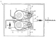
図1は、本発明の実施の形態に係る定着装置を適用した画像形成装置の模式図であり、同図に示す画像形成装置は、色分解に対応した色の画像を形成可能な感光体を複数備え、各感光体上で形成されたトナー像を中間転写体に重畳転写した画像を記録用紙などのシートに対して一括転写することで多色画像を形成可能なカラープリンタである。本発明では、画像形成装置として、カラープリンタに限らず、カラー複写機、ファクシミリ装置および印刷機なども含まれること勿論である。
Embodiments of the present invention will be described below with reference to examples shown in the drawings.
FIG. 1 is a schematic diagram of an image forming apparatus to which a fixing device according to an embodiment of the present invention is applied. The image forming apparatus shown in FIG. 1 includes a photoconductor that can form an image of a color corresponding to color separation. This is a color printer that is provided with a plurality of images and can form a multicolor image by collectively transferring an image obtained by superimposing and transferring the toner image formed on each photoconductor onto an intermediate transfer body onto a sheet such as a recording sheet. In the present invention, the image forming apparatus is not limited to a color printer, but of course includes a color copying machine, a facsimile machine, and a printing machine.
図1において、カラープリンタ1は、画像形成部1Aが縦方向の中央部に位置し、その下方には給紙部1Bが、さらに画像形成部1Aの上方には原稿載置台1C1を備えた原稿走査部1Cがそれぞれ配置されている。
画像形成部1Aには、水平方向に展張面を有する中間転写ベルト2が配置されており、中間転写ベルト2の上位には、色分解色と補色関係にある色の画像を形成するための構成が設けられている。
In FIG. 1, in a color printer 1, an image forming unit 1A is positioned at a central portion in the vertical direction, a document feeding unit 1B is provided below the image forming unit 1A, and an original document table 1C1 is provided above the image forming unit 1A. Each of the scanning units 1C is arranged.
An
画像形成部1Aには、補色関係にある色のトナー(イエロー、マゼンタ、シアン、ブラック)による画像を担持可能な感光体3Y、3M、3C、3Bが中間転写体2の展張面に沿って並置されている。
各感光体3Y、3M、3C、3Bはそれぞれ同じ方向(図1では、反時計方向)に回転可能なドラムで構成されており、その周辺には、回転過程において画像形成処理を実行する帯電装置4,書き込み装置5,現像装置6,1次転写装置7,およびクリーニング装置8が配置されている(便宜上、感光体3Yを対象として、各装置の符号にYを付して示してある)。
In the image forming unit 1A, photoreceptors 3Y, 3M, 3C, and 3B capable of carrying images of toners of complementary colors (yellow, magenta, cyan, and black) are juxtaposed along the extended surface of the
Each of the photoconductors 3Y, 3M, 3C, and 3B is composed of a drum that can rotate in the same direction (counterclockwise in FIG. 1), and a charging device that performs image forming processing in the rotation process around the drum. 4, a writing device 5, a developing device 6, a primary transfer device 7, and a cleaning device 8 are arranged (for convenience, the reference numeral of each device is indicated by Y for the
中間転写ベルト2は、複数のローラ2A〜2Cに掛け回されて感光体との対峙位置において同方向に移動可能な構成を備え、展張面を構成するローラ2A、2Bとは別のローラ2Cは、中間転写ベルト2を挟んで2次転写装置9に対峙している。なお、図1中、符号10は、中間転写ベルト2を対象としたクリーニング装置を示している。
The
2次転写装置9は、帯電駆動ローラ9Aおよび従動ローラ9Bに掛け回されて2次転写装置9が位置する2次転写位置において中間転写ベルト2と同方向に移動可能な転写ベルト9Cを備えており、転写ベルト9Cを帯電駆動ローラ9Aにより帯電させることで中間転写ベルト2に重畳された多色画像あるいは担持されている単一色の画像をシートに転写することができる。
The
2次転写位置には給紙部1Bからシートが給送されるようになっている。
給紙部1Bは、複数の給紙カセット1B1と、給紙カセット1B1から繰り出されるシートの搬送路に配置された複数の搬送ローラ1B2と、2次転写位置前方に位置するレジストローラ1B3とを備えている。本実施例では、給紙部1Bには、給紙トレイ1B1から繰り出されるシートの搬送路に加えて給紙カセット1B1内に収容されていない種類のシートを2次転写位置に向け給送できる構成が備えられており、この構成は、画像形成部1Aの壁面の一部を起倒可能に設けた手差しトレイ1A1と繰り出しコロ1A2とを備えている。
給紙カセット1B1からレジストローラ1B3に向けたシートの搬送路途中には、手差しトレイ1A1から繰り出されたシートの搬送路が合流し、いずれの搬送路から給送されるシートもレジストローラ1B3によってレジストタイミングが設定されるようになっている。
A sheet is fed from the sheet feeding unit 1B to the secondary transfer position.
The paper feed unit 1B includes a plurality of paper feed cassettes 1B1, a plurality of transport rollers 1B2 arranged in a transport path for sheets fed from the paper feed cassette 1B1, and a registration roller 1B3 positioned in front of the secondary transfer position. ing. In this embodiment, the sheet feeding unit 1B can feed a sheet of a type not stored in the sheet feeding cassette 1B1 to the secondary transfer position in addition to the sheet conveyance path fed out from the sheet feeding tray 1B1. This configuration includes a manual feed tray 1A1 and a feeding roller 1A2 provided with a part of the wall surface of the image forming unit 1A that can be raised and lowered.
In the middle of the sheet conveyance path from the sheet feeding cassette 1B1 to the registration roller 1B3, the sheet conveyance path fed from the manual feed tray 1A1 joins, and the sheet fed from any conveyance path is registered by the registration roller 1B3. Timing is set.
書き込み装置5は、原稿走査部1Cに有する原稿載置台1C1上の原稿を走査することにより得られる画像情報あるいは図示しないコンピュータから出力される画像情報により書き込み光が制御されて感光体4Y、4M、4C、4Bに対して画像情報に応じた書き込み光を出射して静電潜像を形成するようになっている。
In the writing device 5, writing light is controlled by image information obtained by scanning a document on the document table 1C1 included in the document scanning unit 1C or image information output from a computer (not shown), and the
原稿走査部1Cには、原稿載置台1C1上の原稿を露光走査するスキャナ1C2が備えられており、さらに原稿載置台1C1の上面には、自動原稿給送装置1C3が配置されている。自動原稿給送装置1C3は、原稿載置台1C1上に繰り出される原稿を反転可能な構成を備え、原稿の表裏各面での走査が行えるようになっている。 The document scanning unit 1C is provided with a scanner 1C2 that exposes and scans the document on the document table 1C1, and an automatic document feeder 1C3 is disposed on the upper surface of the document table 1C1. The automatic document feeder 1C3 has a configuration capable of reversing the document fed on the document table 1C1, and can perform scanning on both sides of the document.
書き込み装置5により形成された感光体3上の静電潜像は現像装置6によって可視像処理され、中間転写ベルト2に1次転写される。中間転写ベルト2に対して各色毎のトナー像が重畳転写されると、2次転写装置9によりシートに対して一括して2次転写される。 2次転写されたシートは、表面に担持している未定着画像を定着装置11によって定着される。定着装置11に関しては後で詳しく説明する。
The electrostatic latent image on the photoreceptor 3 formed by the writing device 5 is subjected to a visible image processing by the developing device 6 and is primarily transferred to the
定着装置11を通過したシートは、定着装置11の後方に配置されている搬送路切り換え爪12によって搬送方向が切り換えられるようになっており、排紙トレイ13に向けた搬送路と、反転搬送路RPとに搬送方向が選択される。
The transport direction of the sheet that has passed through the fixing
以上のような構成を備えたカラープリンタ1では、原稿載置台1C1上に載置された原稿を露光走査することにより、あるいはコンピュータからの画像情報により、一様帯電された感光体3に対して静電潜像が形成され、静電潜像が現像装置6によって可視像処理された後、トナー像が中間転写ベルト2に1次転写される。
In the color printer 1 having the above-described configuration, the uniformly charged photoconductor 3 is exposed and scanned by the document placed on the document placing table 1C1 or by image information from the computer. An electrostatic latent image is formed, and the electrostatic latent image is subjected to visible image processing by the developing device 6, and then the toner image is primarily transferred to the
中間転写ベルト2に転写されたトナー像は、単一色画像の場合にはそのまま給紙部1Bから繰り出されたシートに対して転写され、多色画像の場合には1次転写が繰り返されることにより重畳された後、シートに対して一括して2次転写される。2次転写後のシートは定着装置11により未定着画像を定着された後、排紙トレイ13あるいは、反転されて再度レジストローラ1B3に向けて給送される。
The toner image transferred to the
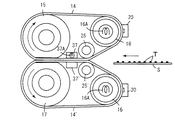
定着装置11は、図2以降の図面に構成が示されている。
本実施例における定着装置11は、対向する展張面が互いに等速で同方向に移動する一対の熱伝導性ベルト14,14’を備えており、熱伝導性ベルト14,14’の展張面においてその展張方向で少なくとも2カ所にシートを挟持できるニップ部N1,N2(図3参照)が設けられ、そのうちの一つのニップ部(N2)が接離可能に構成されている。このため、熱伝導性ベルト14,14’における展張面でのニップ部は、一方のニップ部(N1)が、常時当接状態を維持される定着ローラ15と加圧ローラとの対向当接位置であり、他方のニップ部(N2)が、接離する加熱ローラ16同士の対向位置である。
ニップ部のうちで他方(N2)は、加熱ローラ16同士が当接した際に、一方と併せて展張面で2カ所のうちで一つのニップ部を構成することができ、接離状態に応じて熱伝導性ベルト14,14’の展張面同士が接触する長さを異ならせることができる。
The structure of the fixing
The fixing
Among the nip portions, the other (N2) can form one nip portion at two locations on the expansion surface together with the one when the
図2において、定着装置11には、シートの画像担持面に対向する側と該画像担持面の反対側、つまりシートの裏面に対向する側とにシートの搬送路を挟んで互いに対向する熱伝導性ベルト14,14’が設けられており、画像担持面に対向する側熱伝導性ベルト14が定着側ベルトとされ、これと反対側が加圧側ベルトとされ、これら両方の熱伝導性ベルト14,14’は、互いに一定した速度で同じ方向に展張面が移動するようになっている。
In FIG. 2, the fixing
定着側の熱伝導性ベルト14は、金属製芯金の表面にシリコーンゴムなどの弾性体層が設けられた回転可能な定着ローラ15と金属製芯金で構成されて熱源を内装している加熱ローラ16とに掛け回された無端ベルトであり、ローラ周面に対向する側、換言すれば、裏面側から順に少なくとも支持層と離型層とを備えている。
The fixing-side heat
支持層としては、耐熱性、機械的強度などによる耐久性に優れた材料が用いられ、本実施例では、ニッケル、アルミニウム、銅、ステンレスなどの金属フィルムや、ポリイミド(PI)、ポリアラミド、ポリアミドイミド、ポリエステル、ポリエーテルエーテルケトン(PEEK)等の高分子樹脂フィルムが用いられる。 As the support layer, a material excellent in durability due to heat resistance, mechanical strength, etc. is used. In this embodiment, a metal film such as nickel, aluminum, copper, stainless steel, polyimide (PI), polyaramid, polyamideimide Polymer resin films such as polyester and polyetheretherketone (PEEK) are used.
離型層としては、耐熱性を持つと共に表面エネルギーの小さい材料が用いられ、本実施例では、シリコーン樹脂、例えばポリテトラフルオロエチレン(PTFE)、テトラフルオロエチレン−パーフルオロアルキルビニルエーテル共重合体(PFA)、テトラフルオロエチレン−ヘキサフルオロプロピレン共重合体(FEP)等の高分子樹脂を含むフッ素樹脂やシリコーンゴム、フッ素ゴムなどの耐熱性ゴムが用いられる。なお、離型層として樹脂層を用いる場合には、中間層として弾性層としての機能を有するシリコーンゴムやフッ素ゴムなどの耐熱性ゴム層を設けることで弾性変形による形状追随性を確保することができる。この性質により定着されるシートへの熱伝達性を向上させることができる。 As the release layer, a material having heat resistance and low surface energy is used. In this embodiment, silicone resin such as polytetrafluoroethylene (PTFE), tetrafluoroethylene-perfluoroalkyl vinyl ether copolymer (PFA) is used. ), A heat-resistant rubber such as a fluororesin including a polymer resin such as tetrafluoroethylene-hexafluoropropylene copolymer (FEP), a silicone rubber, or a fluororubber. When a resin layer is used as the release layer, it is possible to ensure shape followability by elastic deformation by providing a heat-resistant rubber layer such as silicone rubber or fluorine rubber having a function as an elastic layer as an intermediate layer. it can. This property can improve heat transfer to the sheet to be fixed.
加圧側の熱伝導性ベルト14’は、定着側の熱伝導性ベルト14と同様に、金属製芯金の表面にシリコーンゴムなどの弾性体層が設けられて加圧ローラ17と加熱ローラ16とに掛け回された無端ベルトで構成されている。
加圧ローラ17は、その回転軸に加圧レバー18が当接しており、加圧レバー18の揺動端に係止されているバネなどの弾性体19の付勢により定着ローラ15に向けて圧接させてある。
The pressure-side heat
The
加熱ローラ16には熱源としてハロゲンヒータ16Aが内蔵されており、熱伝導性ベルト14,14’の表面に当接しているサーミスタなどの温度制御素子20によって熱伝導性ベルト14,14’の表面温度が所定温度となるように熱源であるハロゲンヒータ16Aの温度制御が実行されるが、本実施例では、加熱ローラ16の接離に拘わらず所定温度に維持されるようになっている。なお、図2中、符号16Bは、熱伝導性ベルト14,14’の片寄りを防止するための部材を示している。
The
図3は、上記構成を備えた定着装置11の動作を説明するための模式図であり、同図において、定着装置11の加熱ローラ16は、熱伝導性ベルト14,14’に対する一定張力を常時維持させることができる張力付勢部材21を備えると共に、互いに接離できる構成を備えている。
FIG. 3 is a schematic diagram for explaining the operation of the fixing
加熱ローラ16には、ソレノイドなどの駆動部材22により往復動可能な作動部材23が回転軸に連結されており、互いに接近する方向に移動した場合には、熱伝導性ベルト14,14’同士が当接する。なお、加熱ローラ16同士は、通常、それらの回転軸間に配置されているバネなどの弾性体24によって互いに離れる向きの移動習性が付与されているようになっている。
An operating
加熱ローラ16同士が接近した際に互いに当接する熱伝導性ベルト14,14’の展張面は、加熱ローラ16同士の接近位置が規定されることでシートの移動方向に平行するようになっており、シートの移動方向と熱伝導性ベルト14,14’の展張面の移動方向とが一致することによりシートを直進させることができるようになっている。これにより、熱伝導性ベルト14,14’の展張面同士が接触すると、シートはこの展張面で挟持搬送されることになるが、搬送路の向きが今までの移動方向に平行しているので、搬送路途中で曲げ力などを受けることがなく、搬送性を損ねることなく移動することができる。
The expansion surfaces of the heat
熱伝導性ベルト14,14’の展張面が互いに接触し展張面の展張方向で2カ所のニップ部(N1,N2)が構成されると、そのニップ部はシートの移動方向と直角な方向で押圧力を作用させ、その作用方向がニップ部同士で平行している。これにより、シートの搬送路は、シートの移動方向をそれまでの搬送方向と異ならせることがなく、シートの直進搬送性を維持できるようになっている。
When the stretched surfaces of the heat
ニップ部は、加熱ローラ16の接離動作に応じて2カ所(N1,N2)に構成されることになり、熱伝導性ベルト14,14’により挟持搬送されるシートに対する熱伝達領域の長さが変更できるようになっている。
The nip portion is configured at two locations (N1, N2) according to the contact / separation operation of the
本実施例では、熱伝達領域の長さを画像に求められる光沢度に応じて設定するようになっており、文字画像の場合には通常光沢度として熱伝達領域が短い場合を選択できるようにし、多色画像の場合には高光沢度として熱伝達領域を長くする場合を選択できるようになっている。 In this embodiment, the length of the heat transfer area is set in accordance with the glossiness required for the image. In the case of a character image, the normal glossiness can be selected when the heat transfer area is short. In the case of a multicolor image, it is possible to select a case where the heat transfer area is lengthened with high glossiness.
本実施例において、2カ所のニップ部間で熱伝導性ベルト14,14’同士が接触した状態が相当する熱伝達領域の長さを長くした場合には、他方のニップ部(N2)側から熱伝導性ベルト14,14’同士が接触している範囲をシートが移動する過程でトナーの温度がTg〜Tmの範囲に設定され、一方のニップ部(N1)において、圧力の作用を受けて定着されるようになっている。
In this embodiment, when the length of the heat transfer region corresponding to the state in which the heat
ニップ部間で熱伝導性ベルト14,14’が接触する範囲は、一方のニップ部(N1)に対してシートの移動方向上流側に位置していることから、一方のニップ部での定着加熱領域に対して予熱領域を構成している。
The range where the heat
シート上のトナーは、予熱領域において昇温することになるが、ニップ部とは違って圧力の影響が少ない。しかし、昇温した状態で溶融し、粘度が低下しているので、一方のニップ部(N1)において圧力の作用を受けることで定着性が得られると共にガラス転移点への昇温によって光沢度を確保されることになる。上記温度範囲のうちで、上限温度Tm°を越えた場合、熱伝導性ベルト14,14’の離型性によってはホットオフセットが生じるので、このような現象が発生しない受熱量が得られる熱伝達領域の長さとすることが望ましい。
The toner on the sheet is heated in the preheating region, but unlike the nip portion, the influence of pressure is small. However, since it melts in a state where the temperature is raised and the viscosity is lowered, the fixability is obtained by receiving the action of pressure at one nip portion (N1) and the glossiness is increased by raising the temperature to the glass transition point. Will be secured. Within the above temperature range, when the upper limit temperature Tm ° is exceeded, hot offset occurs depending on the releasability of the heat
加熱ローラ16同士を当接させない場合には、上述した予熱領域が構成されないので、一方のニップ部(N1)における定着加熱領域での受熱量のみがトナーに付与されることになる。
When the
予熱領域の長さを変更することにより光沢度を変更する際には、画像の光沢度を変更する際の要因である未定着画像に対する受熱量を熱伝導性ベルトの接離動作により切り換えるだけですむので、シートの移動速度、所謂、線速さらには温度の切り換えや圧力の変更などを要しないようにすることができる。 When changing the glossiness by changing the length of the preheating area, it is only necessary to switch the amount of heat received on the unfixed image, which is a factor in changing the glossiness of the image, by the contact / separation operation of the heat conductive belt. Therefore, it is possible to eliminate the need to change the sheet moving speed, the so-called linear speed, or the temperature switching or the pressure.
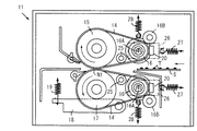
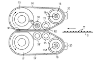
次に、上記熱伝導性ベルト14,14’における熱伝達領域の長さを変更するための構成に関する別実施例を図4において説明する。
図4に示す実施例は、熱伝導性ベルト14,14’における展張面で定着ローラおよび加圧ローラとの対向位置である一方のニップ部(N1)、そして加熱ローラ同士が接離する他方のニップ部の他にニップ部(便宜上、図5において符号N2’で示すニップ部)を設け、このニップ部での接離動作に応じて熱伝達領域の長さを変更できるようにした構成が特徴である。
図4において、定着側の熱伝導性ベルト14におけるニップ部間、および定着側と対応して加圧側の熱伝導性ベルト14’におけるニップ部間には、熱伝導性ベルト14,14’同士の展張面を接離させる領域設定用部材(便宜上、定着側に位置する部材を符号25により、加圧側に位置する部材を符号25’によりそれぞれ示す)が設けられている。領域設定用部材25,25’は、互いに接離する方向に移動することで熱伝導性ベルト14,14’の展張面における熱伝達領域の長さを変更できるようになっている。
Next, another embodiment relating to a configuration for changing the length of the heat transfer region in the heat
In the embodiment shown in FIG. 4, one nip portion (N 1) that is a position facing the fixing roller and the pressure roller on the stretched surface of the heat
In FIG. 4, between the nip portions of the heat
領域設定用部材25,25’は、熱伝導性ベルト14,14’の裏面に当設して連動回転可能なローラで構成されており、熱伝導性ベルト14,14’同士の熱伝達領域を長くする押圧位置と、その長さを設定しない非押圧位置とに往復動できる部材である。以下、領域設定用部材25,25’の接離動作に係る構成を説明する。
図4において、符号26は、加熱ローラ16の回転軸を軸支しながら定着ローラ15および加圧ローラ17に対して加熱ローラ16との軸間距離を大きくさせる習性をバネなどの弾性体27によって付与されている軸支部材であり、領域設定用部材25,25’の接離動作に関係なく熱伝導性ベルト14,14’の張力を一定に保持するようになっている。その作用は次の通りである。
The
In FIG. 4,
熱伝導性ベルト14,14’が領域設定用部材25,25’の接近により互いに接触すると熱伝導性ベルト14,14’の対向する展張面が図4に示す直線状から図5に示すように相手側の熱伝導性ベルトの展張面に向けて膨出することになる。このため、加熱ローラ16には、熱伝導性ベルト14,14’の展張面同士が接触する向きに負荷を受ける。加熱ローラ16が熱伝導性ベルト14,14’の膨出方向への動きを規制されていると熱伝導性ベルト14,14’の張力が変化してしまう。
When the heat
本実施例では、熱伝導性ベルト14,14’の接離動作に関係なく一定張力を維持するための構成として、図4において加熱ローラ16に掛け止められたバネなどの弾性体28を用いることにより熱伝導性ベルト14,14’の膨出方向とは反対側に加熱ローラ16を常時牽引するようになっている。これにより、熱伝導性ベルト14,14’同士を接触させる際に展張面の一部が互いに接触する向きに膨出すると、その膨出方向への負荷が加熱ローラ16に作用することになるので、加熱ローラ16が弾性体28の付勢に抗して移動することができ、張力の増加を防ぐようになっている。
In this embodiment, as a configuration for maintaining a constant tension regardless of the contact / separation operation of the heat
領域設定用部材25,25’は、熱伝導性ベルト14,14’同士を接触させた際に加熱ローラ16よりも互いに接触する熱伝導性ベルト14,14’の展張面側に位置するようになっている。これにより、展張面でのシート導入側は、加熱ローラ16から張り出される展張面同士が楔状の空間を構成する。
The
本実施例では、楔状空間、換言すれば、シートの移動方向前方側が先細となる空間での開き角度が10°以上、好ましくは10〜30°に設定できるように加熱ローラ16の位置と接近状態にある領域設定部材25,25’の位置とが規定されている。これにより、両方の熱伝導性ベルト14,14’の開口角度が小さい場合に起こりがちなシートのばたつきを防止して定着前の画像が擦られてしまうのを防止することができる。
In the present embodiment, the position of the
本実施例は、以上のような構成であるから、高光沢度が選択された場合には、熱伝導性ベルト14,14’同士が接触するように加熱ローラ16同士を接近させる。
熱伝導性ベルト14,14’同士が接触すると、図6に示すように、各ニップ部(N1,N2)間でシート上の未定着画像に対する予熱領域L2および一方のニップ部(N1)における定着加熱領域L1が構成される。これにより、未定着画像中のトナーの温度がTg〜Tmに設定され、予熱領域L2においてトナー層が十分に溶融してトナーの粘度を下げることができ、この状態で一方のニップ部(N1)において圧力を作用させることで画像の光沢度を上昇させることができる。
Since the present embodiment is configured as described above, when high glossiness is selected, the
When the heat
予熱領域L2の長さと定着加熱領域L1との長さは同じではなく、各領域での機械的な条件が異なることでシートに対する受熱量も異なっているので、受熱量を均衡させるために、各領域間での長さの関係を設定することが望ましい。
本実施例においては、熱伝導性ベルト14,14同士のみの圧接である予熱領域の方が、互いに圧力と熱の作用を受ける定着加熱領域よりも受熱量が少ない。このため、予熱領域での熱伝達領域の長さを定着加熱領域での熱伝達領域の長さに対して1.5〜2.0倍となる関係を設定し、これに基づき、予熱領域の長さ、還元すれば、領域設定用部材25,25’の配置位置を規定している。
Since the length of the preheating region L2 and the length of the fixing heating region L1 are not the same, and the amount of heat received by the sheet is different due to the different mechanical conditions in each region, in order to balance the amount of received heat, It is desirable to set the length relationship between regions.
In the present embodiment, the preheating region where only the heat
次に、領域設定用部材25,25’の接離機構に関する構成の変形例を説明する。
図7において、領域設定用部材25,25’の回転軸には加熱ローラ16の回転軸を支点とする揺動レバー29,29’の揺動端の一方が係合している。
揺動レバー29,29’の揺動端の他方には領域設定用駆動源となる領域用ソレノイド30,30’のアクチュエータが連結されている。
揺動端の他方には、アクチュエータが連結される側と反対側にバネ31の一端が掛け止められており、領域用ソレノイド30,30’の非励磁時には定着側の揺動レバー29を図4において時計方向に、そして加圧側の揺動レバー29’を反時計方向に揺動させる習性が付与されている。
Next, a modified example of the configuration related to the contact / separation mechanism of the
In FIG. 7, one of the swinging ends of the swinging
The other of the swinging ends of the swing levers 29 and 29 ′ is connected to an actuator for the region solenoids 30 and 30 ′ serving as a region setting drive source.
The other end of the swing end is hooked with one end of a
揺動レバー29,29’の習性により領域設定用部材25,25’は、領域用ソレノイド30,30’の非励磁時が相当する初期状態の時において、熱伝導性ベルト14,14’同士が離れる位置に位置決めされ、領域用ソレノイド30,30’が励磁されると、バネ31の習性に抗して熱伝導性ベルト14,14’同士を接触させることができる位置に位置決めされる。
Due to the habits of the swing levers 29 and 29 ′, the
図7に示す構成では、領域設定用部材25,25’が熱伝導性ベルト14,14’同士を接触させる場合、熱伝導性ベルト14,14’の張り出しによる加熱ローラ16の軸心位置を自動的に調整して、熱伝導性ベルト14,14’同士が接触した場合においても非接触の時と同様な張力を維持できるようになっている。
In the configuration shown in FIG. 7, when the
図7において、加熱ローラ16の回転軸に装備されている軸支持部材26は、左向きのT字状をなすアンカー部材32に対して弾性体27を介して連動できるようになっており、さらにアンカー部材32の中央部には、加熱ローラ16を定着ローラ15および加圧ローラ17から引き離す方向に付勢する引張りバネ33が不動部との間に掛け止められている。
In FIG. 7, the
アンカー部材32には、軸支持部材側に張力調整用ソレノイド34のアクチュエータが連結されている。
The
張力調整用ソレノイド34は、加熱ローラ16が接離するのに応じてアンカー部材32を往復動させるための駆動源であり、領域用ソレノイド30,30’の動作に連動して励磁態位が設定される。張力調整用ソレノイド34は、通常、領域用ソレノイド30,30’の非励時タイミングと同期して非励時の状態が維持されている。
The
張力調整用ソレノイド34による熱伝導性ベルト14,14’の張力一定化は次の原理に基づき実行される。
弾性体27と引張バネ33とは同じ方向に付勢力を有し、その付勢力、つまり、弾性復元力(P1,P2)は、P1<P2とされている。これによって、張力調整用ソレノイド34の非励磁時には、弾性体27および引張りバネ33の弾性力との差が軸支持部材26に作用することで加熱ローラ16を定着ローラ15および加圧ローラ17から離す方向に牽引することができる。このときには、領域用ソレノイド30,30’が非励時状態にあるので、領域設定用部材25,25’がバネ31に牽引されて互いに離れているので、熱伝導性ベルト14,14’は弛みを生じることなく一定張力を付与される。
The tension of the heat
The
張力調整用ソレノイド34が励磁されると、張力調整用ソレノイド34におけるアクチュエータを引き動かす力(F)が弾性体27および引張りバネ33の弾性力以上に発生することで、アンカー部材32が張力調整用ソレノイド34の引力(F)と弾性体27および引張りバネ33との間での力の差との違いにより、アンカー部材32が張力調整用ソレノイド34の引力発生方向に移動する。これにより、加熱ローラ16が定着ローラ15および加圧ローラ17側に接近することができ、熱伝導性ベルト14,14’に弛みを与えるが、熱伝導性ベルト14,14’は領域用ソレノイド30,30’の励磁が行われていることにより領域設定用部材25,25’が熱伝導性ベルト14,14’の対向展張面同士を接触させる向きに膨出させるので、熱伝導性ベルト14,14’の張力は領域設定用部材25,25’同士が接近しない場合と略同じ張力に維持されることになる。
When the
領域用ソレノイド30,30’および張力調整用ソレノイド34が励磁されると、領域設定用部材25,25’同士が接近するので、一方のニップ部N1に連続してシートSの移動方向前方に熱伝導性ベルト14,14’同士の接触による予熱領域が構成される。
When the
領域用ソレノイド30,30’および張力調整用ソレノイド34は、図8に示す制御部によって駆動態位が設定される。
図8において制御部35は、画像形成部での画像形成処理制御を行うマイクロコンピュータにより主要部が構成されており、図示しないI/Oインターフェースを介して入力側には本実施例に関係する部材として熱伝導性ベルト14,14’の温度を検知するサーミスタ20、操作パネル36およびシートの通過を検知するセンサ類(図5では、便宜上、シート検知センサと表示する)が接続され、出力側には画像形成部での処理に陥られる駆動部(図5においては纏めて駆動部と表示してある)、領域用ソレノイド30,30’、張力調整用ソレノイド34が接続されている。
操作パネル36には、モード選択スイッチが設けられており、モード選択スイッチは、ユーザによる画像の光沢度を選択するために設けられている。
The region solenoids 30 and 30 'and the
In FIG. 8, the
The
画像の光沢度は、初期特性として、低光沢度(低光沢モード)が設定されており、ユーザによりこの光沢度以上(高光沢モード)を選択できるようになっている。
光沢度に関しては、文字画像および写真画像いずれの場合にも選択できるが、とくに、カラー画像を要望されることが多い写真画像の場合には、低光沢モードの場合に反射率が20〜30%とされ、高光沢モードの場合には50〜60%の反射率を設定できるようになっている。
制御部35では、操作パネル36で行われる1ジョブ毎の光沢度選択に応じてシートに対するニップの形成状態を設定し、熱伝導性ベルト14,14’による熱伝達領域の長さを設定するようになっている。
The glossiness of the image is set to low glossiness (low gloss mode) as an initial characteristic, and the user can select a glossiness higher than this glossiness (high gloss mode).
The glossiness can be selected for both character images and photographic images. In particular, in the case of photographic images that often require color images, the reflectance is 20 to 30% in the low gloss mode. In the high gloss mode, a reflectance of 50 to 60% can be set.
The
本実施例は以上のような構成であるから、制御部35の動作を示す図9のフローチャートに基づき作用を説明すると次の通りである。
図9においてユーザによる高光沢モードの選択有無が判別される(ST1)。
ステップST1において高光沢モードが選択されると、領域用ソレノイド30,30’および張力調整用ソレノイド34のいずれもが励磁(ON)される(ST2)。
Since the present embodiment is configured as described above, the operation will be described as follows based on the flowchart of FIG. 9 showing the operation of the
In FIG. 9, it is determined whether or not the user has selected the high gloss mode (ST1).
When the high gloss mode is selected in step ST1, both the
領域用ソレノイド30,30’および張力調整用ソレノイド34がそれぞれ励磁されると、図7に示すように、領域設定用部材25,25’が互いに接近する方向に移動し、熱伝導性ベルト14,14’同士を接触させる。これに伴い、加熱ローラ16の軸支持部材26は、アンカー部材32の変位に応じて領域設定用部材25,25’による熱伝導性ベルト14,14’の膨出を許容するように熱伝導性ベルト14,14’に弛みを与えることができ、領域設定用部材25,25’が互いに接近した際の熱伝導性ベルト14,14’の張力を熱伝導性ベルト14,14’により予熱領域が構成されない初期状態と同様な張力に維持する。
When the
各ソレノイドの励磁が完了すると、一方のニップ部N1に加えて、領域設定用部材25,25’によって他方のニップ部(便宜上、図7中、符号N2’で示す)に連続する予熱領域が熱伝導性ベルト14,14’同士の接触範囲に構成され、さらに熱伝導性ベルト14,14’におけるシートが導入される側の展張面がシートの移動方向に沿って前方から後方に向け先細となる錘状空間とされる。これにより、加熱ローラ16からの熱は、予熱領域にも至り、シートが予熱領域において予熱され、トナーの温度が上限温度であるT1/2f°に近づけられる。
When excitation of each solenoid is completed, in addition to one nip portion N1, a preheating region continuous to the other nip portion (indicated for convenience by N2 'in FIG. 7) is heated by the
各ソレノイドの励磁に併せてシートの給送が開始され(ST3)、画像形成処理が実行されてシートに対してトナー像の転写が行われる(ST4)。画像形成処理後、定着装置11に向けてシートが導入されるのを導入検知センサにより検知する(ST5)。この検知は、搬送過程においてシートの搬送不良が発生した場合、接触している状態に維持されている熱伝導性ベルト14,14’を離すためである。なお、このような処理は、加熱ローラ16でのサーミスタの温度管理が厳密であって、熱伝導性ベルト14,14’に過熱状態が発生しないのであれば、必ずしも必要ではない。
Along with the excitation of each solenoid, the sheet feeding is started (ST3), the image forming process is executed, and the toner image is transferred to the sheet (ST4). After the image forming process, the introduction detection sensor detects that the sheet is introduced toward the fixing device 11 (ST5). This detection is for releasing the heat
定着装置11からシートが排出されるのをシート検知センサを用いて検知した場合(ST6)には、1ジョブあたりでの設定枚数の判別が行われ(ST7)、設定枚数の達するまでの間、熱伝導性ベルト14,14’の接触状態が維持され、設定枚数に達すると、領域用ソレノイド30,30’および張力調整用ソレノイド34の励磁状態が解除されて初期状態に復帰し(ST8)、領域設定用部材25,25’が互いに離れ、熱伝導性ベルト14,14’同士が離れる。
When it is detected by the sheet detection sensor that the sheet is discharged from the fixing device 11 (ST6), the set number of sheets per job is determined (ST7), and until the set number of sheets is reached. When the contact state of the heat
以上のような実施例によれば、熱伝導性ベルト14,14’同士が接触して予熱領域を構成した場合には、ベルト同士が同じ方向に同一速度で移動するので、シートの表裏両面で相対的な速度差を生じることがなく、これにより、定着途中で未定着画像が擦られて乱れてしまうのを防止することができる。
According to the embodiment as described above, when the heat
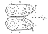
次に本発明の実施形態に係る他の実施例について説明する。
図10は、他の実施例を示す定着装置の模式図であり、同図に示されている実施例は、熱伝導性ベルト14,14’のニップ間にベルト同士の接触状態を維持するための補助加圧部材を各ベルトの裏面側に設けたことを特徴としている。
Next, another example according to the embodiment of the present invention will be described.
FIG. 10 is a schematic view of a fixing device according to another embodiment. In the embodiment shown in FIG. 10, the contact state between the belts is maintained between the nips of the heat
図10に示す補助加圧部材37、37’は、熱伝導性ベルト14,14’の展張面における一方のニップ部N1と領域設定部材25,25’同士が接近してベルト14,14’を押圧することで得られる他方のニップ部N2’との間に配置された背圧部材(以下、図10に示す補助加圧部材を背圧部材と称する)で構成されており、背圧部材37、37’は、低摩擦係数で熱伝導性が低い材質からなり、熱伝導性ベルト14,14’の裏面で予熱領域の略全域に面接触することができるようになっている。
The
本実施例によれば、熱伝導性ベルト14,14’同士のみの接触によりシートに対する熱伝達を行う際に、熱伝導性ベルト14,14’とシートとの密着性を高めて熱伝達効率を向上させることができる。特に背圧部材37により予熱領域での熱伝導性ベルト14,14’の浮き上がりを防止してシートを挟持搬送することができるので、シートが直進する際の抵抗となることがなく、搬送性を良好に維持することができる。
According to the present embodiment, when heat transfer to the sheet is performed only by contact between the heat
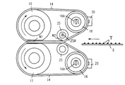
図11は、補助加圧部材の構成に関する変形例を示す図であり、同図に示す補助加圧部材38、38’はローラで構成されている。ローラで構成されている補助加圧部材38,38’は、予熱領域において単一もしくは複数並置して設けられ、熱伝導性ベルト14,14’の移動に連動して回転しながらシートの挟持搬送を可能にしている。
図11に示す構成によれば、補助加圧部材38,38’の当接時には熱伝導性ベルト14,14’の移動を阻害しないで回転するので、ベルト同士での速度差を生じることがなく、トナーへの擦れ現象の発生を防止しながら予熱領域での加熱伝達が可能となる。
FIG. 11 is a view showing a modification of the configuration of the auxiliary pressure member, and the
According to the configuration shown in FIG. 11, when the
次に、上記予熱領域を対象とした他の実施例について説明する。
図12に示す実施例は、熱伝導性ベルト14,14’のニップ間に位置する予熱領域を加熱することを特徴としている。
Next, another embodiment for the preheating region will be described.
The embodiment shown in FIG. 12 is characterized in that the preheating region located between the nips of the heat
図12において、予熱領域を構成する領域設定用部材25,25’におけるシートSの未定着画像面に対向する側の領域設定用部材25には、熱源25Aが内蔵されている。これにより、加熱ローラ16によって加熱されて温度の維持が行われている熱伝導性ベルト14,14’に対してシートSが導入された際に発生する温度降下を抑えることができる。つまり、予熱領域にシートが導入されるとそれまで予熱に必要な温度に維持されている熱伝導性ベルトの温度が下降し、熱伝導性ベルト14,14に熱容量不足が生じる。特に熱伝導性ベルト14,14’は、金属製ローラ同士によりシートを加熱する場合と違って熱容量が小さいためにシートと接触した際に急激な温度下降が生じる。そこで、図12に示す実施例では、領域設定用部材25に熱源25Aを内蔵させて予熱領域での温度下降を防止している。
In FIG. 12, the
この実施例によれば、熱伝達領域の長さを長くできる部材である領域設定用部材25を予熱領域での加熱源とすることができるので、最も温度降下が顕著となる領域設定用部材25,25’同士の対向当接位置で温度低下による未定着画像への熱量不足を防止して定着加熱領域での設定温度との差を小さくし、光沢度を高めることが可能となる。特に連続通紙が行われた際には、複数枚のシートの給送が行われると予熱領域での温度降下が顕著となりやすいが、本実施例では、温度降下が抑えられるので、連続通紙においても安定した光沢度を得るための受熱状態を維持することができる。
According to this embodiment, since the
予熱領域での加熱構造に関しては、図12に示した領域設定用部材の一つ(図12中、符号25で示す領域設定用部材)にのみ熱源25Aを設けることに限らず、図13、図14に示すように、予熱領域内に配置されている補助加圧部材37,38に熱源を設けることも可能である。この場合には、実際に未定着画像に接触する側の熱伝導性ベルト14の裏面に位置する補助加圧部材37あるいは38において熱源37Aあるいは38Aを内蔵すればよい。さらに、領域設定用部材およびまたは補助加圧部材を対象として加熱源を設けることも可能である。
The heating structure in the preheating region is not limited to providing the
次に、本発明の実施形態に係るさらに別の実施例について説明する。
図15に示す実施例は、予熱領域に位置する領域設定用部材25,25’あるいは補助加圧部材37,38とは別に予熱領域での熱伝導性ベルト14の加熱を行う構成を備えたことを特徴としている。
図15において、予熱領域におけるシートの画像面に対向する位置で、一方のニップ部(N1)近傍には、シートの移動方向において定着加熱領域をなすニップ部(N1)の前方に相当する位置に、画像面に対向する熱伝導性ベルト14の裏面側からベルト14を輻射加熱するヒータ39が設けられている。
Next, another example according to the embodiment of the present invention will be described.
The embodiment shown in FIG. 15 has a configuration for heating the heat
In FIG. 15, at a position facing the image surface of the sheet in the preheating region, in the vicinity of one nip portion (N1), a position corresponding to the front of the nip portion (N1) forming the fixing heating region in the sheet moving direction. A
本実施例においては、定着加熱領域の前方においてシートの導入により温度降下している熱伝導性ベルト14を加熱するので、定着加熱領域である一方のニップ部(N1)に達する直前で上限温度との差を小さくして定着加熱領域での上限温度への到達時間を短くして光沢度を高めることが可能となる。
In this embodiment, since the heat
次に上記実施例における予熱領域の加熱構造の変形例を説明する。
図16に示す構成は、予熱領域を構成する他方のニップ部(N2)に位置する領域設定用部材のうちで、未定着画像に対向する領域設定用部材25にヒートパイプ40を装備したことを特徴としている。
領域設定用部材25においては、シートの移動方向と直角な方向に相当する幅方向で均一の温度分布が要求される。特に、熱伝導性ベルト14,14’の幅に対してこれよりも狭い幅の小サイズのシートを給送する際には、幅方向端部において230℃程度に温度上昇する場合があり、このような場合には領域設定用部材25の熱的劣化や大判サイズでの幅方向での温度偏差による光沢度の偏差の発生、さらには、ホットオフセットの発生という不具合がある。
Next, a modification of the heating structure in the preheating region in the above embodiment will be described.
The configuration shown in FIG. 16 is that the
The
図16に示す構成では、熱伝導性ベルト14に直接接触する領域設定用部材25をヒートパイプ(便宜上、符号40で示す)で構成してある。このような構成によれば、幅方向での温度勾配を均一化することができ、特にシートを連続して給送する際に発生する温度降下による温度差が生じた場合でも、温度勾配を均して幅方向での温度差をなくすことができる。さらに、この変形例としては、図示しないが、領域設定用部材25だけでなく、補助加圧部材30に対しても同様な構成とすることも可能である。
In the configuration shown in FIG. 16, the
上記実施例に関して、図8に示した制御部35は、図7に示した構成における領域設定用部材の接離制御に限らず、図示はしてないものの、動作原理が同じである図4に示した領域設定用部材を対象とした接離制御に用いることも可能である。また、各実施例においては、シートの片面に担持されている未定着画像の定着を対象として説明しているが、本発明では、シートの両面に未定着画像が存在する場合も対象とすることも勿論可能である。
この場合には、定着ローラと加圧ローラとが本発明の実施形態において挙げられているように同じ構成であると、ニップ形態の水平状態となり、薄紙の搬送性が良好で皺などの発生が見られないが、両面定着時には紙種によって加圧ローラ側に巻き付くこともあり得る。そこで、このような場合には、定着ローラ側のゴム硬度を低くして軟らかくしたりあるいは定着ローラ側の厚みをやや厚くして一方のニップ部でのニップ形態をシートの放出方向がやや加圧ローラ側に向くようにして上述した巻き付きなどを起こりにくくして必要な受熱状態と搬送性とを得るようにすることもできる。
With respect to the above embodiment, the
In this case, when the fixing roller and the pressure roller have the same configuration as described in the embodiment of the present invention, the nip form is horizontal, the thin paper is transportable, and wrinkles are generated. Although not seen, it may be wound around the pressure roller side depending on the paper type during double-sided fixing. Therefore, in such a case, the rubber hardness on the fixing roller side is lowered to make it softer, or the fixing roller side is made slightly thicker so that the nip form at one nip portion is slightly pressurized in the sheet discharge direction. It is also possible to obtain the necessary heat receiving state and transportability by making it face the roller side so that the above-described winding or the like is less likely to occur.
1 画像形成装置の一例であるカラープリンタ
2 中間転写ベルト
3 感光体
4 帯電装置
5 書き込み装置
6 現像装置
7 1次転写用転写装置
9 2次転写用転写装置
11 定着装置
14,14’ 熱伝導性ベルト
15 定着ローラ
16 加熱ローラ
17 加圧ローラ
25 領域設定用部材
30,30’ 領域設定部材の接離駆動源であるソレノイド
37,37’,38,38’ 補助加圧部材
N1 定着ローラと加圧ローラとが常時当接している一方のニップ部
N2 加熱ローラ同士が接離する他方のニップ部
N2’ 領域設定用部材同士が接離する他方のニップ部
L1 定着加熱領域
L2 予熱領域
S シート
DESCRIPTION OF SYMBOLS 1 Color printer which is an example of
Claims (23)
対向する展張面が互いに同方向に移動する状態で設けられている一対の熱伝導性ベルトと、
上記各熱伝導性ベルトにおいて対向する展張面の展張方向で少なくとも2カ所において該熱伝導性ベルト間に挟持されるシートを押圧するニップ部とを備え、
上記ニップ部のうちの一方は上記熱伝導性ベルト同士が常時当接し、他方は熱伝導性ベルト同士が互いに接離する関係とされ、接離状態に応じて上記展張面同士が対向して構成されるシートへの熱伝達領域の長さが変更可能であることを特徴とする定着装置。 An apparatus for fixing an unfixed image carried on a sheet,
A pair of thermally conductive belts provided in a state in which opposing stretched surfaces move in the same direction;
A nip portion that presses a sheet sandwiched between the thermal conductive belts in at least two locations in the extending direction of the opposing extending surfaces in each of the thermal conductive belts,
One of the nip portions is always in contact with the heat conductive belts, and the other is in contact with and away from each other, and the stretched surfaces face each other according to the contact and separation state. The fixing device is characterized in that the length of the heat transfer area to the sheet to be applied can be changed.
上記他方のニップ部の位置は、上記シートの移動方向上流側に位置していることを特徴とする定着装置。 The fixing device according to claim 1.
The fixing device according to claim 1, wherein the position of the other nip portion is located upstream of the sheet in the moving direction.
上記熱伝導性ベルトは一対のローラに掛け回されて展張面が構成され、該ローラの一つには、加熱源が内蔵されて該熱伝導性ベルトを加熱することを特徴とする定着装置。 The fixing device according to claim 1 or 2,
A fixing device, wherein the heat conductive belt is wound around a pair of rollers to form a stretched surface, and one of the rollers has a built-in heating source to heat the heat conductive belt.
上記熱伝導性ベルトは、上記他方のニップ部の接離動作に関係なく一定速度で移動することを特徴とする定着装置。 The fixing device according to any one of claims 1 to 3,
The fixing device according to claim 1, wherein the heat conductive belt moves at a constant speed regardless of the contact / separation operation of the other nip portion.
上記熱伝導性ベルトは、上記他方のニップ部の接離に関係なく一定張力を維持されていることを特徴とする定着装置。 The fixing device according to any one of claims 1 to 3,
The fixing device according to claim 1, wherein the heat conductive belt is maintained at a constant tension regardless of the contact and separation of the other nip portion.
上記一方および他方のニップ部は、上記シートの搬送方向に平行する熱伝導性ベルトの移動方向に対して直角に押圧力を作用させ、該押圧力の作用方向が両方のニップ部同士で平行していることを特徴とする定着装置。 The fixing device according to any one of claims 1 to 5,
The one nip portion and the other nip portion exert a pressing force at right angles to the moving direction of the heat conductive belt parallel to the sheet conveying direction, and the acting direction of the pressing force is parallel between both nip portions. A fixing device.
上記ニップ部のうちで、他方のニップ部は、シートに対する加熱状態の選択に応じて接離する関係とされていることを特徴とする定着装置。 The fixing device according to any one of claims 1 to 6, wherein:
Among the nip portions, the other nip portion is in contact with and separated from the sheet according to the selection of the heating state for the sheet.
上記他方のニップ部での加熱状態は、上記シート上に担持されている未定着画像の光沢度を基準として選択されることを特徴とする定着装置。 The fixing device according to claim 7.
The fixing device is characterized in that the heating state at the other nip portion is selected on the basis of the glossiness of an unfixed image carried on the sheet.
上記熱伝導性ベルトは一対のローラに掛け回されていて、その一対のローラ間には、対向する展張面同士を接離させて上記シートの熱伝達領域の長さを変更可能な領域設定部材が設けられていることを特徴とする定着装置。 The fixing device according to any one of claims 1 to 8,
The heat conductive belt is wound around a pair of rollers, and an area setting member capable of changing the length of the heat transfer area of the sheet by contacting and separating the facing extending surfaces between the pair of rollers. And a fixing device.
上記熱伝導性ベルト同士の接離関係を設定する領域設定用部材はローラで構成され、該領域設定用ローラは、上記熱伝導性ベルト同士の熱伝達領域が長くできる位置とその長さを設定しない位置とに変位可能であることを特徴とする定着装置。 The fixing device according to any one of claims 1 to 9,
The region setting member for setting the contact / separation relationship between the heat conductive belts is constituted by a roller, and the region setting roller sets a position where the heat transfer region between the heat conductive belts can be lengthened and its length. A fixing device characterized in that it can be displaced to a position where it does not.
上記領域設定用ローラは、上記熱伝導性ベルト同士を接触させることで一方のニップ部で構成される加熱定着領域近傍に予熱領域を構成することを特徴とする定着装置。 The fixing device according to claim 10.
The region setting roller forms a preheating region in the vicinity of a heat fixing region formed by one nip portion by bringing the heat conductive belts into contact with each other.
上記領域設定用ローラは、上記シートの移動方向において上記加熱定着領域に連続して上記予熱領域を構成できるように上記熱伝導性ベルト同士の接触状態を設定することを特徴とする定着装置。 The fixing device according to claim 11.
The fixing device according to claim 1, wherein the region setting roller sets a contact state between the heat conductive belts so that the preheating region can be configured continuously to the heat fixing region in the moving direction of the sheet.
上記領域設定用部材には、上記熱伝導性ベルトの加熱用熱源が設けられていることを特徴とする定着装置。 The fixing device according to any one of claims 8 to 12,
The fixing device, wherein the region setting member is provided with a heat source for heating the heat conductive belt.
上記領域設定用部材と上記一方のニップ部との間には、上記他方のニップ部とは別に上記熱伝導性ベルト同士の接触状態を維持する補助加圧部材が設けられていることを特徴とする定着装置。 The fixing device according to any one of claims 8 to 13, wherein
An auxiliary pressurizing member is provided between the region setting member and the one nip portion to maintain the contact state between the heat conductive belts separately from the other nip portion. Fixing device to do.
上記補助加圧部材は、上記熱伝導性ベルトの対向面と反対面に配置されて当接している背圧部材で構成されていることを特徴とする定着装置。 The fixing device according to claim 14.
The fixing device according to claim 1, wherein the auxiliary pressure member is a back pressure member disposed on and in contact with the opposite surface of the heat conductive belt.
上記補助加圧部材は、上記熱伝導性ベルトの対向面と反対面で回転可能かつ接離可能なローラで構成されていることを特徴とする定着装置。 The fixing device according to claim 14.
The fixing device according to claim 1, wherein the auxiliary pressure member is constituted by a roller that is rotatable and can be contacted / separated on a surface opposite to a surface facing the heat conductive belt.
上記領域設定用部材および上記補助加圧部材の少なくとも一方には上記熱伝導性ベルトの加熱用熱源が設けられていることを特徴とする定着装置。 The fixing device according to claim 14.
At least one of the region setting member and the auxiliary pressure member is provided with a heat source for heating the heat conductive belt.
上記補助加圧部材をなす背圧部材は、低摩擦係数かつ低熱伝導度を有することを特徴とする定着装置。 The fixing device according to claim 15.
The fixing device according to claim 1, wherein the back pressure member forming the auxiliary pressure member has a low coefficient of friction and a low thermal conductivity.
上記領域設定用部材および補助加圧部材の少なくとも一つが、自身で加熱源をなすヒートパイプで構成されていることを特徴とする定着装置。 The fixing device according to claim 17.
At least one of the region setting member and the auxiliary pressure member is constituted by a heat pipe that serves as a heating source itself.
上記熱伝導性ベルトの移動方向における上記領域設定用部材または上記補助加熱部材と上記一方のニップ部との間には、上記熱伝導性ベルトの加熱用熱源が配置されていることを特徴とする定着装置。 The fixing device according to any one of claims 9, 14 to 19,
A heat source for heating the heat conductive belt is disposed between the region setting member or the auxiliary heating member and the one nip portion in the moving direction of the heat conductive belt. Fixing device.
上記熱伝導性ベルトの移動方向における上記領域設定部材または上記補助加圧部材は、上記熱伝導性ベルト同士の接触時、上記一方のニップで構成される定着加熱領域に連続してその上流側に位置する予熱領域を構成することを特徴とする定着装置。 The fixing device according to claim 20, wherein
The region setting member or the auxiliary pressure member in the moving direction of the heat conductive belt is continuously upstream of the fixing heating region formed by the one nip when the heat conductive belts are in contact with each other. A fixing device comprising a preheating region positioned.
Priority Applications (1)
| Application Number | Priority Date | Filing Date | Title |
|---|---|---|---|
| JP2007166545A JP2007241320A (en) | 2007-06-25 | 2007-06-25 | Fixing device and image forming apparatus |
Applications Claiming Priority (1)
| Application Number | Priority Date | Filing Date | Title |
|---|---|---|---|
| JP2007166545A JP2007241320A (en) | 2007-06-25 | 2007-06-25 | Fixing device and image forming apparatus |
Related Parent Applications (1)
| Application Number | Title | Priority Date | Filing Date |
|---|---|---|---|
| JP2001015347A Division JP3993983B2 (en) | 2001-01-24 | 2001-01-24 | Fixing apparatus and image forming apparatus |
Publications (2)
| Publication Number | Publication Date |
|---|---|
| JP2007241320A true JP2007241320A (en) | 2007-09-20 |
| JP2007241320A5 JP2007241320A5 (en) | 2007-11-01 |
Family
ID=38586849
Family Applications (1)
| Application Number | Title | Priority Date | Filing Date |
|---|---|---|---|
| JP2007166545A Pending JP2007241320A (en) | 2007-06-25 | 2007-06-25 | Fixing device and image forming apparatus |
Country Status (1)
| Country | Link |
|---|---|
| JP (1) | JP2007241320A (en) |
Cited By (2)
| Publication number | Priority date | Publication date | Assignee | Title |
|---|---|---|---|---|
| US9946203B2 (en) * | 2016-09-02 | 2018-04-17 | Kabushiki Kaisha Toshiba | Fixing device for changing a nip width |
| JP2019136865A (en) * | 2018-02-06 | 2019-08-22 | コニカミノルタ株式会社 | Heating apparatus and inkjet recording device |
-
2007
- 2007-06-25 JP JP2007166545A patent/JP2007241320A/en active Pending
Cited By (3)
| Publication number | Priority date | Publication date | Assignee | Title |
|---|---|---|---|---|
| US9946203B2 (en) * | 2016-09-02 | 2018-04-17 | Kabushiki Kaisha Toshiba | Fixing device for changing a nip width |
| JP2019136865A (en) * | 2018-02-06 | 2019-08-22 | コニカミノルタ株式会社 | Heating apparatus and inkjet recording device |
| JP7047427B2 (en) | 2018-02-06 | 2022-04-05 | コニカミノルタ株式会社 | Heating device and inkjet recording device |
Similar Documents
| Publication | Publication Date | Title |
|---|---|---|
| JP5223697B2 (en) | Belt drive device, fixing device, and image forming apparatus | |
| JP5339072B2 (en) | Fixing apparatus and image forming apparatus | |
| JP4447565B2 (en) | Fixing apparatus and image forming apparatus | |
| US8401452B2 (en) | Fixing device with gloss control unit and image forming apparatus | |
| JP5517591B2 (en) | Fixing device | |
| US8666273B2 (en) | Image heating device | |
| AU2008217011B2 (en) | Fixing device, image forming apparatus, fixing method and image forming method | |
| US8457540B2 (en) | Fixing device and image forming apparatus incorporating same | |
| US9207602B2 (en) | Image heating apparatus | |
| US7783219B2 (en) | Fixing apparatus having a fixing member and an external heating device, and image forming apparatus including the same | |
| JP2010281871A (en) | Fixing device and image forming apparatus | |
| JP6454903B2 (en) | Image forming apparatus | |
| JP2018165791A (en) | Fixing device and image forming apparatus | |
| JP2013160908A (en) | Image heating device | |
| JP3993983B2 (en) | Fixing apparatus and image forming apparatus | |
| JP5369907B2 (en) | Belt fixing device and image forming apparatus having the same | |
| JP2013140214A (en) | Image forming device | |
| KR20030076272A (en) | Image-forming apparatus | |
| JP2004184446A (en) | Fixing device and image forming apparatus | |
| JP2007101861A (en) | Fixing device | |
| JP4844267B2 (en) | Fixing apparatus and image forming apparatus using the same | |
| JP2005140994A (en) | Image forming apparatus | |
| JP2007241320A (en) | Fixing device and image forming apparatus | |
| US9110417B2 (en) | Fixing apparatus and image forming apparatus including the fixing apparatus | |
| US10754281B2 (en) | Fixing belt, fixing device, image forming apparatus, and image forming method capable of coping with both low glossiness and high glossiness |
Legal Events
| Date | Code | Title | Description |
|---|---|---|---|
| A621 | Written request for application examination |
Free format text: JAPANESE INTERMEDIATE CODE: A621 Effective date: 20070725 |
|
| A521 | Written amendment |
Free format text: JAPANESE INTERMEDIATE CODE: A523 Effective date: 20070829 |
|
| A131 | Notification of reasons for refusal |
Free format text: JAPANESE INTERMEDIATE CODE: A131 Effective date: 20071120 |
|
| A02 | Decision of refusal |
Effective date: 20080212 Free format text: JAPANESE INTERMEDIATE CODE: A02 |