JP2007240380A - Intra-tunnel position detector - Google Patents
Intra-tunnel position detector Download PDFInfo
- Publication number
- JP2007240380A JP2007240380A JP2006064543A JP2006064543A JP2007240380A JP 2007240380 A JP2007240380 A JP 2007240380A JP 2006064543 A JP2006064543 A JP 2006064543A JP 2006064543 A JP2006064543 A JP 2006064543A JP 2007240380 A JP2007240380 A JP 2007240380A
- Authority
- JP
- Japan
- Prior art keywords
- tunnel
- vehicle
- image processing
- angle
- position detection
- Prior art date
- Legal status (The legal status is an assumption and is not a legal conclusion. Google has not performed a legal analysis and makes no representation as to the accuracy of the status listed.)
- Withdrawn
Links
Images


Landscapes
- Length Measuring Devices By Optical Means (AREA)
- Navigation (AREA)
- Traffic Control Systems (AREA)
Abstract
Description
本発明は、GPS信号を受信できないトンネル内で自車位置を検出するトンネル内位置検出装置に関する。 The present invention relates to an in-tunnel position detection device that detects the position of a host vehicle in a tunnel that cannot receive a GPS signal.
現在、目的地までの経路を探索し、これを案内するナビゲーションシステムが開発され、車両、または携帯端末等で利用されている。ナビゲーション装置は、車両位置を検出する方式として、GPS衛星から電波を受信して測位するGPS方式と、車速センサおよびジャイロセンサ等を利用した自立航法方式の2種類がある。これらを併用し、車両の現在位置と現在の方位を検出している。高層ビル群などのGPS衛星からの電波受信環境が良くない場所では、自立航法方式のみを使用するが、細かい動きや長距離走行で蓄積する誤差が発生しやすい。このような問題を解決するための、車両位置の検出方法が提案されている。 Currently, a navigation system that searches for a route to a destination and guides the route is developed and used in a vehicle, a portable terminal, or the like. There are two types of navigation devices for detecting the vehicle position: a GPS method for receiving radio waves from GPS satellites and a self-contained navigation method using a vehicle speed sensor and a gyro sensor. These are used together to detect the current position and direction of the vehicle. In places where the radio wave reception environment from GPS satellites such as high-rise buildings is not good, only the self-contained navigation method is used. A vehicle position detection method for solving such a problem has been proposed.
特許文献1は、路面の表示線を画像処理によって認識し、車両の位置を正確に検出する方法である。従来の自立航法方式と比較し、表示線を常に基準に補正することができるためより正確に車両の位置を検出し正確な誘導案内を提供することができる。 Patent Document 1 is a method for accurately detecting the position of a vehicle by recognizing a display line on a road surface by image processing. Compared with the conventional self-contained navigation system, the display line can always be corrected based on the reference, so that the position of the vehicle can be detected more accurately and an accurate guidance can be provided.
ナビゲーション装置において、GPS方式は、軌道上のGPS衛星の電波で絶対位置を測定するものであるが、トンネル内では、GPS衛星からの電波を受信することができないため、自立航法方式を利用する。しかしながら、自立航法方式は、上記したように相対的な変化量を加算するため、誤差が蓄積され、長いトンネルやカーブの大きなトンネルでは無視できないほどの大きな誤差が発生し、正確に自車位置を検出することができず、誤った誘導案内を行ってしまうという課題がある。一方、特許文献1で開示されている位置検出方法は、道路によっては、表示線が明確でない道路もあるために認識率が低下してしまい、トンネル内の十分な位置検出方法とは言えない。 In the navigation apparatus, the GPS system measures the absolute position with the radio wave of the GPS satellite in the orbit. However, since the radio wave from the GPS satellite cannot be received in the tunnel, the autonomous navigation system is used. However, in the self-contained navigation method, the relative change amount is added as described above, so errors are accumulated, and a large error that cannot be ignored occurs in a long tunnel or a tunnel with a large curve. There is a problem that it cannot be detected and erroneous guidance is performed. On the other hand, the position detection method disclosed in Patent Document 1 cannot be said to be a sufficient position detection method in a tunnel because the recognition rate decreases because some roads have unclear display lines.
本発明は、上記課題を解決すべく、GPS衛星からの電波が受信できないトンネル内でも、自車位置を正確に検出することができる、トンネル内位置検出装置およびこれを用いたナビゲーション装置を提供することを目的としている。 In order to solve the above problems, the present invention provides an in-tunnel position detection device and a navigation device using the same that can accurately detect the position of the host vehicle even in a tunnel in which radio waves from GPS satellites cannot be received. The purpose is that.
本発明は、GPS衛星からの電波が受信できないトンネル内での位置を検出する機能に関する。自車がトンネル内に進入したことが確認されると、トンネル内の位置検出プログラムが起動される。自車の左右のドアミラーには、おおよそ180°程度の視野角を持つ光学系を含む、2つの撮像カメラが設置されており、その撮像カメラで、トンネル内を撮像し、撮像された画像データを解析することでトンネル内にある照明を検出し、自車から照明までの距離と角度(相対的位置関係)を検出する。検出された照明までの距離と角度に基づき、進行方向上にある自車の前後位置と、進行方向に対して垂直な左右方向上にある自車の左右位置とを算出することで、トンネル内での自車位置を検出する。 The present invention relates to a function for detecting a position in a tunnel where radio waves from a GPS satellite cannot be received. When it is confirmed that the vehicle has entered the tunnel, a position detection program in the tunnel is activated. The left and right door mirrors of the vehicle are equipped with two imaging cameras including an optical system with a viewing angle of about 180 °. The imaging camera captures the inside of the tunnel and captures the captured image data. By analyzing, the lighting in the tunnel is detected, and the distance and angle (relative positional relationship) from the vehicle to the lighting are detected. Based on the detected distance and angle to the lighting, the front-rear position of the vehicle in the direction of travel and the left-right position of the vehicle in the left-right direction perpendicular to the direction of travel are calculated. The position of the vehicle at is detected.
本発明に係るトンネル内自車位置検出装置は、自車がトンネル内に侵入したか否かを判定する判定手段と、判定手段によりトンネル内に自車が進入したと判定されたとき、自車の左右に取り付けられた撮像カメラによりトンネル内を撮像する撮像手段と、撮像手段により撮像された画像データからトンネル内の照明の位置を解析し、照明と自車との相対的位置関係を検出する画像処理手段と、画像処理手段により算出された相対的位置関係に基づき、トンネル内の自車位置を算出する位置算出手段とを有する。 The self-vehicle position detecting device in the tunnel according to the present invention includes a determining means for determining whether or not the own vehicle has entered the tunnel, and when the determining means determines that the own vehicle has entered the tunnel, Imaging means for imaging the inside of the tunnel with imaging cameras attached to the left and right of the vehicle, and analyzing the position of the illumination in the tunnel from the image data captured by the imaging means, and detecting the relative positional relationship between the illumination and the vehicle Image processing means and position calculation means for calculating the position of the vehicle in the tunnel based on the relative positional relationship calculated by the image processing means.
好ましくは、前記位置算出手段は、画像処理手段により検出された相対的位置関係に基づき、トンネル内での進行方向に垂直となる左右の位置を算出する第1の位置算出手段と、トンネル内での進行方向の位置を算出する第2の位置算出手段とを含む。画像処理手段は、自車の左右の各撮像カメラにより撮像された画像データから自車の左右に存在する照明と自車との左側角度および右側角度を検出し、前記第1の位置算出手段は、左側角度と右側角度を比較し、その比較結果に基づき、自車の左右位置を検出する。好ましくは、前記画像処理手段は、自車の左右の少なくとも一方の撮像カメラにより撮像された画像データから自車の前後に存在する照明と自車との前方角度または後方角度を検出し、第2の位置算出手段は、前方角度または後方角度の少なくとも一方により自車の進行方向の位置を検出する。 Preferably, the position calculation means includes first position calculation means for calculating left and right positions perpendicular to the traveling direction in the tunnel based on the relative positional relationship detected by the image processing means, and in the tunnel. Second position calculating means for calculating a position in the traveling direction of the first position. The image processing means detects the left angle and the right angle between the illumination and the own vehicle, which are present on the left and right of the own vehicle, from the image data captured by the left and right imaging cameras of the own vehicle, and the first position calculating means is The left angle and the right angle are compared, and the left and right positions of the vehicle are detected based on the comparison result. Preferably, the image processing means detects a front angle or a rear angle between the illumination existing before and behind the own vehicle and the own vehicle from image data captured by at least one of the left and right imaging cameras of the own vehicle, The position calculation means detects the position in the traveling direction of the host vehicle based on at least one of the front angle and the rear angle.
本発明によれば、トンネル内の照明と自車との相対的な位置関係を検出することで、より正確にトンネル内の自車位置を算出することができ、トンネル内における分岐点および車線変更等で正確な誘導案内を提供することができる。 According to the present invention, by detecting the relative positional relationship between the lighting in the tunnel and the host vehicle, the host vehicle position in the tunnel can be calculated more accurately, and the branch point and lane change in the tunnel can be calculated. Thus, accurate guidance can be provided.
本発明の最良の実施の形態について図面を参照して詳細に説明する。 The best mode for carrying out the present invention will be described in detail with reference to the drawings.
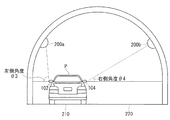
図1は、本発明の実施例に係るトンネル内位置検出装置の構成を示すブロック図である。図2(a)は、車両の上面図であり、図2(b)は、車両の背面図ある。トンネル内位置検出装置100は、図2に示すように車両の左右のドアミラーに設置された撮像カメラ102、104と、周囲の明るさを検出する光センサ106と、撮像カメラ102、104により撮像された画像データを受け取り、画像データを解析してトンネル内の照明などを検出する画像処理部110と、自車位置を算出するプログラムや演算処理を行うマイクロコントローラ112と、トンネル内で自車位置を検出するプログラムや、演算処理データ等を記憶するメモリ114と、検出された自車位置を出力する出力部116によって構成されている。
FIG. 1 is a block diagram showing the configuration of the in-tunnel position detecting apparatus according to the embodiment of the present invention. FIG. 2A is a top view of the vehicle, and FIG. 2B is a rear view of the vehicle. As shown in FIG. 2, the in-tunnel position detection apparatus 100 is picked up by the
左右のドアミラーに設置された撮像カメラ102、104は、CCD撮像素子と、約180°程度の視野角θ1、θ2を持つ光学系とを含む。好ましくは、撮像カメラ102、104は、道路面に対し水平かつ進行方向に対し垂直に光軸を合わせた魚眼レンズを含み、その光軸を中心とした180°のお椀状の範囲を撮像する。本実施例では、2つの撮像カメラを用いてトンネル内を撮像するが、これに限らず、より多くの撮像カメラを用いてトンネル内を撮像してもよい。撮像カメラは、トンネル内専用の撮像カメラである必要は無く、自車がトンネル内を走行していないときには、自車周囲の障害物等を検出するものであってもよい。また、撮像カメラの取り付け位置は、必ずしもドアミラーに限るものではない。
The
画像処理部110は、撮像カメラ102、104からの画像データを解析し、トンネル内の照明位置を検出する。より多くの複数の撮像カメラを用いてトンネル内を撮像する場合には、複数の撮像カメラによって撮像された画像データを合成し、あたかも自車を中心とする一定範囲内のトンネル内を撮像するように視点変換し、そこから照明を抽出するようにしてもよい。
The
図3は、トンネル内の構成例を示す図である。トンネル内に車線210、220の2車線が通っており、トンネルの両側の内壁には、ほぼ一定の間隔で照明200a〜206a、200b〜206bが設置されている。Pは、走行している自車位置である。
FIG. 3 is a diagram illustrating a configuration example in the tunnel. Two lanes of
次に、図3に示すようなトンネル内を走行するときの自車位置検出方法について図4のフローチャートを参照して説明する。先ず、自車がトンネル内に侵入すると、マイクロコントローラ112は、光センサ106の出力に基づき、自車がトンネル内に侵入したと判定する(ステップS101)。これより、マイクロコントローラ112は、トンネル内位置検出プログラムを起動させ、画像処理部110を制御する。画像処理部110は、ドアミラーに設置された撮像カメラ102、104で撮像された画像データを解析し、トンネル内にある照明を検出するとともに、自車と照明との相対的位置関係を検出する(ステップS102)。
Next, the vehicle position detection method when traveling in a tunnel as shown in FIG. 3 will be described with reference to the flowchart of FIG. First, when the own vehicle enters the tunnel, the
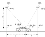
図5は、画像処理部110により画像データを自車背面方向から視点変換した状態、すなわち、自車を背面方向から投影した状態を示している。ここで、撮像カメラ102から左側方向にある照明200aとの左側角度をθ3とし、撮像カメラ104から右側方向にある照明200bとの右側角度をθ4とする。画像処理部110は、トンネル内に侵入したと判定されると、撮像カメラ102、104からの画像データを一定周期で画像処理し、自車位置Pと左右の照明との角度θ3、θ4を検出する。
FIG. 5 shows a state in which the
次に、マイクロコントローラ112は、画像処理部110からの検出結果を受け取り、トンネル内の進行方向に対して垂直方向の左右位置を算出する(ステップS103)。マイクロコントローラ112は、画像処理部110によって検出された左側角度θ3と右側角度θ4とを比較し、角度が大きい側の車線に自車が位置していると判定する。例えば、トンネル内が2車線210、220のとき、左側角度θ3と右側角度θ4との関係がθ3>θ4であれば、マイクロコントローラ112は、左側角度θ3を検出した撮像カメラ102が設置されている左側の車線210に自車位置Pがあると判定する。その反対に、θ3<θ4であれば、自車が右側の車線220に位置していると判定する。ここでは、2車線道路の例を示したが、2車線以上の道路であってもよい。その場合、2つの角度θ3とθ4との差分の間に車線数に応じた複数のしきい値を設定することで、どの車線を走行しているかを判定することができる。また、トンネル内の道路の車線数はナビゲーション装置に含まれるリンク情報を参照するようにしてもよい。
Next, the
次に、マイクロコントローラ112は、トンネル内の進行方向上にある自車の前後位置を算出する(ステップS104)。図6は、画像処理部110により画像データを自車側面方向から視点変換した状態、すなわち自車の側面方向から投影した状態を示している。画像処理部110は、マイクロコントローラ112の左右位置の算出結果に基づき、左側ドアミラーに設置された撮像カメラ102により撮像された画像データを解析し、自車が走行している左側車線の内壁に設置されている照明200a〜200dを検出する。ここで、撮像カメラ102と照明200aとの成す角を後方角度θ5とし、撮像カメラ102と照明202aとの成す角を前方角度θ6とし、撮像カメラ102から照明200aまたは202aまでの高さをHとする。画像処理部110は、画像データを一定の周期で解析し、前方または後方角度θ5、θ6および高さHを検出する。
Next, the
マイクロコントローラ112は、画像処理部110からの検出結果を受け取り、前後位置を算出する。すなわち、画像処理部110によって検出された照明の位置の高さHと、後方角度θ5または前方角度θ6に基づき、距離Aまたは距離Bを求め、前後位置を算出する。例えば、仮に照明202aの座標を(X2,H)、200aの座標を(X1,H)としたとき、距離Aは、H×tan-1θ5で求めることができ、距離Bも同様に、H×tan-1θ6で求めることができる。よって前後位置は、(X1+A,0)、または(X2−B,0)となる。
The
マイクロコントローラ112は、第1の位置算出手法で算出された進行方向に対して垂直な方向上にある左右位置と、第2の位置算出手法で算出された進行方向上にある前後位置とを組み合わせ、トンネル内での自車位置Pを特定する(ステップS105)。マイクロコントローラ112は、光センサ106の出力を監視し、自車がトンネル外であるか否かを判定する(ステップS106)。トンネル内であれば、一連の動作を繰り返す。また、トンネル外であれば、トンネル内位置検出動作を終了する。なお、上記実施例では、トンネル内か否かを光センサを用いて行うようにしたが、これに限らず、他の検出方法を用いてもよい。さらに、自車の左右位置の検出に、画像データを自車背面方向から投影するようにした画像データを、自車前面方向から投影するようにしてもよい。
The
図7は、図1に示すトンネル内位置検出装置100をナビゲーション装置200に適応したときの構成を示すブロック図である。同図に示すように、ナビゲーション装置200は、撮像カメラ102、104、画像処理部110、内部バスと接続されるバスインターフェース210、GPS衛星からの電波を受信して車両の現在位置と現在方位を測位するGPS受信機212、アンテナ214を介して車両外部の現在の道路交通情報を受信するVICS(Vehicle Information and Communication System)・FM多重レシーバ216、操作パネル222、音声入力部224およびリモコン操作部226を含むユーザ入力インターフェース220、大容量のハードディスクを有する記憶装置230、無線または有線によりデータ通信を可能とするデータ通信制御部232、スピーカ242から音声を出力させる音声出力部240、ディスプレイ252に画像を表示させる表示制御部250、プログラムを記憶するプログラムメモリ260、データを一時記憶するデータメモリ270、および制御部280を含んでいる。
FIG. 7 is a block diagram showing a configuration when the in-tunnel position detecting device 100 shown in FIG. 1 is applied to the navigation device 200. As shown in the figure, the navigation device 200 receives the radio waves from the
記憶装置230は、ナビゲーションの各種機能を実行するためのプログラムおよびデータベースを記憶する。データベースは、地図データ、施設データ等を含み、地図データは、道路に関するリンク(道路)データおよび交差点データを含む。リンクデータは、交差点と交差点とを連結する道路に関するデータであり、道路の始点と終点の経緯度を示すノードデータ、道路の種別(国道、一般道、県道など)を示すデータ、幅員、規制(例えば、一方通行)、車線数、トンネル内か否かなどのデータを含んでいる。
The
プログラムメモリ260は、記憶装置230に記憶されたプログラムをロードする。例えば、GPS受信機212の測位結果に基づく自車位置の算出を行う自車位置算出プログラム262、自車位置を地図データの道路(リンク)上にマップマッチングするプログラム264、目的地までの最適経路(最適ルート)を探索するルート探索プログラム266、トンネル内で位置を検出する位置検出プログラム268等を格納する。データメモリ270は、目的地までの経路データ272、GPS受信機212により測位された測位データ274、記憶装置230から読み出された自車位置に対応する地図データ276、トンネル内の照明位置278等を記憶する。制御部280は、これらのプログラムに従い、各部の動作を制御する。
The
図8は、トンネル内位置検出装置100をナビゲーション装置200に適応したときの動作を示すフローチャートである。制御部280は、例えば、GPS受信機212により検出された自車位置から自車がトンネル内に侵入したと判断すると(ステップS201)、トンネル内位置検出プログラム268を起動し(ステップS202)、トンネル内の自車位置を検出する(ステップS203)。検出された位置は、制御部280により地図データ276上にマップマッチングされ(ステップS204)、次に、表示制御部250を介し、表示部252に表示される(ステップS205)。そして、トンネル内であるか否かが判定され(ステップS206)、トンネル内であれば、一連の動作を繰り返す。また、トンネル外であれば、トンネル内位置検出プログラムが終了される(ステップS207)。
FIG. 8 is a flowchart showing an operation when the in-tunnel position detection device 100 is adapted to the navigation device 200. For example, when the
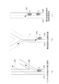
図9は、ナビゲーション装置200によるトンネル内の誘導案内表示例を示す図である。例えば、図9(a)に示すようにトンネル内の分岐点を右折するとき、従来のナビゲーション装置では、トンネル内で自車位置Pを正確に特定できず、誤った誘導案内302を行うことがあったが、ナビゲーション装置200は、トンネル内位置特定プログラムを起動し、自車位置Pを正確に特定し、正確な誘導案内300を行うことができる。また、図9(b)に示すようにトンネルTを退出した直後にある分岐点を左折する場合、トンネル内で車線変更が必要となり、ナビゲーション装置200は、車線220から車線210へ車線変更するように誘導案内304を行う。さらに、図9(c)に示すように、自車が車線220を走行中に後方から緊急車両Eが接近してきた場合、ナビゲーション装置200は、ユーザに対して車線220から車線210へ車線を変更するように誘導案内306を行う。この場合、緊急車両Eは、撮像カメラ102、104により検出するようにしてもよい。
FIG. 9 is a diagram illustrating a guide guidance display example in the tunnel by the navigation device 200. For example, as shown in FIG. 9A, when turning right at a branch point in a tunnel, the conventional navigation apparatus cannot accurately identify the vehicle position P in the tunnel and may perform an
以上、本発明の好ましい実施の形態について詳述したが、本発明に係る特定の実施形態に限定されるものではなく、特許請求の範囲に記載された本発明の要旨の範囲内において、種々の変形・変更が可能である。 The preferred embodiments of the present invention have been described in detail above. However, the present invention is not limited to the specific embodiments according to the present invention, and various modifications can be made within the scope of the gist of the present invention described in the claims. Deformation / change is possible.
本発明に係るトンネル内位置検出装置は、車両等に搭載されるナビゲーション装置、ナビゲーションシステム、あるいはナビゲーション機能を包含するコンピュータ等の電子装置において利用することができる。 The in-tunnel position detection apparatus according to the present invention can be used in an electronic apparatus such as a navigation apparatus, a navigation system, or a computer including a navigation function mounted on a vehicle or the like.
100:トンネル内位置検出装置 102、104:撮像カメラ
106:センサ 110:画像処理部
112:マイクロコントローラ 114:メモリ
116:出力部 200a〜206a:照明
200b〜206b:照明 200:ナビゲーション装置
230:記憶装置
100: Position detection device in
Claims (7)
自車がトンネル内に侵入したか否かを判定する判定手段と、
判定手段によりトンネル内に自車が進入したと判定されたとき、自車の左右に取り付けられた撮像カメラによりトンネル内を撮像する撮像手段と、
撮像手段により撮像された画像データからトンネル内の照明の位置を解析し、照明と自車との相対的位置関係を検出する画像処理手段と、
画像処理手段により算出された相対的位置関係に基づき、トンネル内の自車位置を算出する位置算出手段と
を有するトンネル内位置検出装置。 A tunnel position detection device for detecting the position of a vehicle in a tunnel,
A determination means for determining whether or not the vehicle has entered the tunnel;
When it is determined by the determination means that the host vehicle has entered the tunnel, the imaging means for imaging the inside of the tunnel with the imaging cameras attached to the left and right of the host vehicle;
Image processing means for analyzing the position of the illumination in the tunnel from the image data captured by the imaging means, and detecting the relative positional relationship between the illumination and the vehicle;
An in-tunnel position detecting device comprising: a position calculating means for calculating the position of the vehicle in the tunnel based on the relative positional relationship calculated by the image processing means.
The in-tunnel position detection device according to any one of claims 1 to 6, and a display unit that displays the position of the vehicle detected by the in-tunnel position detection device on road map data. Navigation device.
Priority Applications (1)
| Application Number | Priority Date | Filing Date | Title |
|---|---|---|---|
| JP2006064543A JP2007240380A (en) | 2006-03-09 | 2006-03-09 | Intra-tunnel position detector |
Applications Claiming Priority (1)
| Application Number | Priority Date | Filing Date | Title |
|---|---|---|---|
| JP2006064543A JP2007240380A (en) | 2006-03-09 | 2006-03-09 | Intra-tunnel position detector |
Publications (1)
| Publication Number | Publication Date |
|---|---|
| JP2007240380A true JP2007240380A (en) | 2007-09-20 |
Family
ID=38586061
Family Applications (1)
| Application Number | Title | Priority Date | Filing Date |
|---|---|---|---|
| JP2006064543A Withdrawn JP2007240380A (en) | 2006-03-09 | 2006-03-09 | Intra-tunnel position detector |
Country Status (1)
| Country | Link |
|---|---|
| JP (1) | JP2007240380A (en) |
Cited By (10)
| Publication number | Priority date | Publication date | Assignee | Title |
|---|---|---|---|---|
| DE102008006445A1 (en) * | 2008-01-28 | 2009-08-20 | Navigon Ag | Method for operating a navigation device |
| KR20170068937A (en) * | 2015-12-10 | 2017-06-20 | 현대모비스 주식회사 | Autonomous driving vehicle navigation system using the tunnel lighting |
| JP2017129508A (en) * | 2016-01-22 | 2017-07-27 | 三菱電機株式会社 | Self-location estimation system, self-location estimation method, mobile terminal, server and self-location estimation program |
| CN107390676A (en) * | 2016-05-17 | 2017-11-24 | 深圳市朗驰欣创科技股份有限公司 | Tunnel crusing robot and tunnel cruising inspection system |
| US10019017B2 (en) * | 2016-02-05 | 2018-07-10 | Toyota Jidosha Kabushiki Kaisha | Autonomous driving system |
| US20190163993A1 (en) * | 2017-11-30 | 2019-05-30 | Samsung Electronics Co., Ltd. | Method and apparatus for maintaining a lane |
| CN110160534A (en) * | 2018-02-11 | 2019-08-23 | 中兴通讯股份有限公司 | A kind of air navigation aid, device, equipment and storage medium |
| KR20200052868A (en) * | 2015-12-10 | 2020-05-15 | 현대모비스 주식회사 | Method And Apparatus for Autonomous Vehicle Navigation System |
| US20200386566A1 (en) * | 2019-06-07 | 2020-12-10 | Toyota Jidosha Kabushiki Kaisha | Self-position sharing system, vehicle, and terminal |
| WO2021232971A1 (en) * | 2020-05-21 | 2021-11-25 | 华为技术有限公司 | Vehicle positioning method and device |
-
2006
- 2006-03-09 JP JP2006064543A patent/JP2007240380A/en not_active Withdrawn
Cited By (14)
| Publication number | Priority date | Publication date | Assignee | Title |
|---|---|---|---|---|
| DE102008006445A1 (en) * | 2008-01-28 | 2009-08-20 | Navigon Ag | Method for operating a navigation device |
| KR102385907B1 (en) * | 2015-12-10 | 2022-04-11 | 현대모비스 주식회사 | Method And Apparatus for Autonomous Vehicle Navigation System |
| KR20170068937A (en) * | 2015-12-10 | 2017-06-20 | 현대모비스 주식회사 | Autonomous driving vehicle navigation system using the tunnel lighting |
| KR20200052868A (en) * | 2015-12-10 | 2020-05-15 | 현대모비스 주식회사 | Method And Apparatus for Autonomous Vehicle Navigation System |
| KR102428765B1 (en) * | 2015-12-10 | 2022-08-02 | 현대모비스 주식회사 | Autonomous driving vehicle navigation system using the tunnel lighting |
| JP2017129508A (en) * | 2016-01-22 | 2017-07-27 | 三菱電機株式会社 | Self-location estimation system, self-location estimation method, mobile terminal, server and self-location estimation program |
| US10019017B2 (en) * | 2016-02-05 | 2018-07-10 | Toyota Jidosha Kabushiki Kaisha | Autonomous driving system |
| CN107390676A (en) * | 2016-05-17 | 2017-11-24 | 深圳市朗驰欣创科技股份有限公司 | Tunnel crusing robot and tunnel cruising inspection system |
| US20190163993A1 (en) * | 2017-11-30 | 2019-05-30 | Samsung Electronics Co., Ltd. | Method and apparatus for maintaining a lane |
| CN110160534A (en) * | 2018-02-11 | 2019-08-23 | 中兴通讯股份有限公司 | A kind of air navigation aid, device, equipment and storage medium |
| US20200386566A1 (en) * | 2019-06-07 | 2020-12-10 | Toyota Jidosha Kabushiki Kaisha | Self-position sharing system, vehicle, and terminal |
| US11761782B2 (en) * | 2019-06-07 | 2023-09-19 | Toyota Jidosha Kabushiki Kaisha | Self-position sharing system, vehicle, and terminal |
| CN113701738A (en) * | 2020-05-21 | 2021-11-26 | 华为技术有限公司 | Vehicle positioning method and device |
| WO2021232971A1 (en) * | 2020-05-21 | 2021-11-25 | 华为技术有限公司 | Vehicle positioning method and device |
Similar Documents
| Publication | Publication Date | Title |
|---|---|---|
| JP2007240380A (en) | Intra-tunnel position detector | |
| US7532975B2 (en) | Imaging apparatus for vehicles | |
| JP4643436B2 (en) | Own vehicle position determination device | |
| US7928905B2 (en) | Method of using road signs to augment global positioning system (GPS) coordinate data for calculating a current position of a personal navigation device | |
| JP6036371B2 (en) | Vehicle driving support system and driving support method | |
| US8055442B2 (en) | Determining a display position of road name data and displaying the road name data | |
| US20070208507A1 (en) | Current position sensing system, map display system and current position sensing method | |
| US8532917B2 (en) | Method, system, and recording medium for navigating vehicle | |
| EP1072863A2 (en) | Image processing apparatus for navigation system | |
| JP2005207999A (en) | Navigation system, and intersection guide method | |
| JP4677981B2 (en) | Own vehicle position identification method and own vehicle position identification device | |
| WO2014128532A1 (en) | Intelligent video navigation for automobiles | |
| JP2019089476A (en) | Parking support device and computer program | |
| JP4339178B2 (en) | Parking space empty space guidance device and parking space empty space guidance method | |
| JP2007218848A (en) | Positional information acquisition system for mobile body | |
| US8756008B2 (en) | Navigation apparatus | |
| JP2008128927A (en) | Navigation system, and navigation device | |
| JP6117671B2 (en) | Vehicle support device | |
| JP2001289652A (en) | Navigator | |
| US11187815B2 (en) | Method of determining location of vehicle, apparatus for determining location, and system for controlling driving | |
| JP2006153565A (en) | In-vehicle navigation device and own car position correction method | |
| JP2007071539A (en) | On-vehicle navigation device | |
| JP2007140992A (en) | Method and device for supporting driving at intersection | |
| KR20200064543A (en) | Control apparatus of camera for autonomous driving vehicle and method thereof | |
| JP4312093B2 (en) | Navigation device, navigation method, and navigation program |
Legal Events
| Date | Code | Title | Description |
|---|---|---|---|
| A300 | Withdrawal of application because of no request for examination |
Free format text: JAPANESE INTERMEDIATE CODE: A300 Effective date: 20090512 |